CN100468530C - Optical disk medium and method and apparatus for reproducing information - Google Patents
Optical disk medium and method and apparatus for reproducing information Download PDFInfo
- Publication number
- CN100468530C CN100468530C CNB2006101388109A CN200610138810A CN100468530C CN 100468530 C CN100468530 C CN 100468530C CN B2006101388109 A CNB2006101388109 A CN B2006101388109A CN 200610138810 A CN200610138810 A CN 200610138810A CN 100468530 C CN100468530 C CN 100468530C
- Authority
- CN
- China
- Prior art keywords
- signal
- information
- track groove
- magnetic track
- message block
- Prior art date
- Legal status (The legal status is an assumption and is not a legal conclusion. Google has not performed a legal analysis and makes no representation as to the accuracy of the status listed.)
- Expired - Fee Related
Links
Images


Classifications
-
- G—PHYSICS
- G11—INFORMATION STORAGE
- G11B—INFORMATION STORAGE BASED ON RELATIVE MOVEMENT BETWEEN RECORD CARRIER AND TRANSDUCER
- G11B27/00—Editing; Indexing; Addressing; Timing or synchronising; Monitoring; Measuring tape travel
- G11B27/10—Indexing; Addressing; Timing or synchronising; Measuring tape travel
- G11B27/19—Indexing; Addressing; Timing or synchronising; Measuring tape travel by using information detectable on the record carrier
- G11B27/28—Indexing; Addressing; Timing or synchronising; Measuring tape travel by using information detectable on the record carrier by using information signals recorded by the same method as the main recording
- G11B27/30—Indexing; Addressing; Timing or synchronising; Measuring tape travel by using information detectable on the record carrier by using information signals recorded by the same method as the main recording on the same track as the main recording
- G11B27/3027—Indexing; Addressing; Timing or synchronising; Measuring tape travel by using information detectable on the record carrier by using information signals recorded by the same method as the main recording on the same track as the main recording used signal is digitally coded
-
- G—PHYSICS
- G11—INFORMATION STORAGE
- G11B—INFORMATION STORAGE BASED ON RELATIVE MOVEMENT BETWEEN RECORD CARRIER AND TRANSDUCER
- G11B20/00—Signal processing not specific to the method of recording or reproducing; Circuits therefor
- G11B20/10—Digital recording or reproducing
- G11B20/10009—Improvement or modification of read or write signals
- G11B20/10222—Improvement or modification of read or write signals clock-related aspects, e.g. phase or frequency adjustment or bit synchronisation
-
- G—PHYSICS
- G11—INFORMATION STORAGE
- G11B—INFORMATION STORAGE BASED ON RELATIVE MOVEMENT BETWEEN RECORD CARRIER AND TRANSDUCER
- G11B20/00—Signal processing not specific to the method of recording or reproducing; Circuits therefor
- G11B20/10—Digital recording or reproducing
- G11B20/12—Formatting, e.g. arrangement of data block or words on the record carriers
- G11B20/1217—Formatting, e.g. arrangement of data block or words on the record carriers on discs
-
- G—PHYSICS
- G11—INFORMATION STORAGE
- G11B—INFORMATION STORAGE BASED ON RELATIVE MOVEMENT BETWEEN RECORD CARRIER AND TRANSDUCER
- G11B20/00—Signal processing not specific to the method of recording or reproducing; Circuits therefor
- G11B20/10—Digital recording or reproducing
- G11B20/14—Digital recording or reproducing using self-clocking codes
- G11B20/1403—Digital recording or reproducing using self-clocking codes characterised by the use of two levels
-
- G—PHYSICS
- G11—INFORMATION STORAGE
- G11B—INFORMATION STORAGE BASED ON RELATIVE MOVEMENT BETWEEN RECORD CARRIER AND TRANSDUCER
- G11B27/00—Editing; Indexing; Addressing; Timing or synchronising; Monitoring; Measuring tape travel
- G11B27/10—Indexing; Addressing; Timing or synchronising; Measuring tape travel
- G11B27/19—Indexing; Addressing; Timing or synchronising; Measuring tape travel by using information detectable on the record carrier
- G11B27/24—Indexing; Addressing; Timing or synchronising; Measuring tape travel by using information detectable on the record carrier by sensing features on the record carrier other than the transducing track ; sensing signals or marks recorded by another method than the main recording
-
- G—PHYSICS
- G11—INFORMATION STORAGE
- G11B—INFORMATION STORAGE BASED ON RELATIVE MOVEMENT BETWEEN RECORD CARRIER AND TRANSDUCER
- G11B7/00—Recording or reproducing by optical means, e.g. recording using a thermal beam of optical radiation by modifying optical properties or the physical structure, reproducing using an optical beam at lower power by sensing optical properties; Record carriers therefor
- G11B7/004—Recording, reproducing or erasing methods; Read, write or erase circuits therefor
- G11B7/005—Reproducing
- G11B7/0053—Reproducing non-user data, e.g. wobbled address, prepits, BCA
-
- G—PHYSICS
- G11—INFORMATION STORAGE
- G11B—INFORMATION STORAGE BASED ON RELATIVE MOVEMENT BETWEEN RECORD CARRIER AND TRANSDUCER
- G11B7/00—Recording or reproducing by optical means, e.g. recording using a thermal beam of optical radiation by modifying optical properties or the physical structure, reproducing using an optical beam at lower power by sensing optical properties; Record carriers therefor
- G11B7/007—Arrangement of the information on the record carrier, e.g. form of tracks, actual track shape, e.g. wobbled, or cross-section, e.g. v-shaped; Sequential information structures, e.g. sectoring or header formats within a track
- G11B7/00745—Sectoring or header formats within a track
-
- G—PHYSICS
- G11—INFORMATION STORAGE
- G11B—INFORMATION STORAGE BASED ON RELATIVE MOVEMENT BETWEEN RECORD CARRIER AND TRANSDUCER
- G11B7/00—Recording or reproducing by optical means, e.g. recording using a thermal beam of optical radiation by modifying optical properties or the physical structure, reproducing using an optical beam at lower power by sensing optical properties; Record carriers therefor
- G11B7/24—Record carriers characterised by shape, structure or physical properties, or by the selection of the material
- G11B7/2407—Tracks or pits; Shape, structure or physical properties thereof
- G11B7/24073—Tracks
- G11B7/24082—Meandering
-
- G—PHYSICS
- G11—INFORMATION STORAGE
- G11B—INFORMATION STORAGE BASED ON RELATIVE MOVEMENT BETWEEN RECORD CARRIER AND TRANSDUCER
- G11B20/00—Signal processing not specific to the method of recording or reproducing; Circuits therefor
- G11B20/10—Digital recording or reproducing
- G11B20/12—Formatting, e.g. arrangement of data block or words on the record carriers
- G11B20/1217—Formatting, e.g. arrangement of data block or words on the record carriers on discs
- G11B2020/1218—Formatting, e.g. arrangement of data block or words on the record carriers on discs wherein the formatting concerns a specific area of the disc
- G11B2020/1221—Formatting, e.g. arrangement of data block or words on the record carriers on discs wherein the formatting concerns a specific area of the disc cluster, i.e. a data structure which consists of a fixed number of sectors or ECC blocks
-
- G—PHYSICS
- G11—INFORMATION STORAGE
- G11B—INFORMATION STORAGE BASED ON RELATIVE MOVEMENT BETWEEN RECORD CARRIER AND TRANSDUCER
- G11B20/00—Signal processing not specific to the method of recording or reproducing; Circuits therefor
- G11B20/10—Digital recording or reproducing
- G11B20/12—Formatting, e.g. arrangement of data block or words on the record carriers
- G11B20/1217—Formatting, e.g. arrangement of data block or words on the record carriers on discs
- G11B2020/1218—Formatting, e.g. arrangement of data block or words on the record carriers on discs wherein the formatting concerns a specific area of the disc
- G11B2020/1238—Formatting, e.g. arrangement of data block or words on the record carriers on discs wherein the formatting concerns a specific area of the disc track, i.e. the entire a spirally or concentrically arranged path on which the recording marks are located
- G11B2020/1239—Formatting, e.g. arrangement of data block or words on the record carriers on discs wherein the formatting concerns a specific area of the disc track, i.e. the entire a spirally or concentrically arranged path on which the recording marks are located the track being a pregroove, e.g. the wobbled track of a recordable optical disc
-
- G—PHYSICS
- G11—INFORMATION STORAGE
- G11B—INFORMATION STORAGE BASED ON RELATIVE MOVEMENT BETWEEN RECORD CARRIER AND TRANSDUCER
- G11B20/00—Signal processing not specific to the method of recording or reproducing; Circuits therefor
- G11B20/10—Digital recording or reproducing
- G11B20/12—Formatting, e.g. arrangement of data block or words on the record carriers
- G11B2020/1264—Formatting, e.g. arrangement of data block or words on the record carriers wherein the formatting concerns a specific kind of data
- G11B2020/1265—Control data, system data or management information, i.e. data used to access or process user data
- G11B2020/1267—Address data
- G11B2020/1268—Address in pregroove [ADIP] information
-
- G—PHYSICS
- G11—INFORMATION STORAGE
- G11B—INFORMATION STORAGE BASED ON RELATIVE MOVEMENT BETWEEN RECORD CARRIER AND TRANSDUCER
- G11B20/00—Signal processing not specific to the method of recording or reproducing; Circuits therefor
- G11B20/10—Digital recording or reproducing
- G11B20/12—Formatting, e.g. arrangement of data block or words on the record carriers
- G11B2020/1264—Formatting, e.g. arrangement of data block or words on the record carriers wherein the formatting concerns a specific kind of data
- G11B2020/1265—Control data, system data or management information, i.e. data used to access or process user data
- G11B2020/1267—Address data
- G11B2020/1274—Address data stored in pre-pits, i.e. in embossed pits, ROM marks or prepits
-
- G—PHYSICS
- G11—INFORMATION STORAGE
- G11B—INFORMATION STORAGE BASED ON RELATIVE MOVEMENT BETWEEN RECORD CARRIER AND TRANSDUCER
- G11B20/00—Signal processing not specific to the method of recording or reproducing; Circuits therefor
- G11B20/10—Digital recording or reproducing
- G11B20/12—Formatting, e.g. arrangement of data block or words on the record carriers
- G11B2020/1264—Formatting, e.g. arrangement of data block or words on the record carriers wherein the formatting concerns a specific kind of data
- G11B2020/1265—Control data, system data or management information, i.e. data used to access or process user data
- G11B2020/1287—Synchronisation pattern, e.g. VCO fields
-
- G—PHYSICS
- G11—INFORMATION STORAGE
- G11B—INFORMATION STORAGE BASED ON RELATIVE MOVEMENT BETWEEN RECORD CARRIER AND TRANSDUCER
- G11B20/00—Signal processing not specific to the method of recording or reproducing; Circuits therefor
- G11B20/10—Digital recording or reproducing
- G11B20/12—Formatting, e.g. arrangement of data block or words on the record carriers
- G11B2020/1291—Formatting, e.g. arrangement of data block or words on the record carriers wherein the formatting serves a specific purpose
- G11B2020/1292—Enhancement of the total storage capacity
-
- G—PHYSICS
- G11—INFORMATION STORAGE
- G11B—INFORMATION STORAGE BASED ON RELATIVE MOVEMENT BETWEEN RECORD CARRIER AND TRANSDUCER
- G11B20/00—Signal processing not specific to the method of recording or reproducing; Circuits therefor
- G11B20/10—Digital recording or reproducing
- G11B20/12—Formatting, e.g. arrangement of data block or words on the record carriers
- G11B2020/1291—Formatting, e.g. arrangement of data block or words on the record carriers wherein the formatting serves a specific purpose
- G11B2020/1298—Enhancement of the signal quality
-
- G—PHYSICS
- G11—INFORMATION STORAGE
- G11B—INFORMATION STORAGE BASED ON RELATIVE MOVEMENT BETWEEN RECORD CARRIER AND TRANSDUCER
- G11B2220/00—Record carriers by type
- G11B2220/20—Disc-shaped record carriers
-
- G—PHYSICS
- G11—INFORMATION STORAGE
- G11B—INFORMATION STORAGE BASED ON RELATIVE MOVEMENT BETWEEN RECORD CARRIER AND TRANSDUCER
- G11B2220/00—Record carriers by type
- G11B2220/20—Disc-shaped record carriers
- G11B2220/25—Disc-shaped record carriers characterised in that the disc is based on a specific recording technology
- G11B2220/2537—Optical discs
Abstract
An optical disk medium includes a track groove thereon. On the optical disk medium, information is recorded along the track groove on a block unit basis. The track groove includes a plurality of unit segment parts which are arranged along the track groove and which have side surfaces displaced periodically along the track groove; the side surfaces of the plurality of unit segment parts uses the shape allocated to each unit segment part, to represent sub information assigned to each unit segment part; each unit segment part has a first side displacement pattern that has been so defined as to make a signal waveform rise relatively steeply and fall relatively gently or a second side displacement pattern that has been so defined as to make a signal waveform rise relatively gently and fall relatively steeply; an identification mark for each unit segment part is allocated atthe head of each unit segment part; the said identification mark has displacement patterns having discriminative first side displacement pattern and second side displacement pattern, and represent the same information as the sub information assigned to the shape of the related unit segment part.
Description
The application is that application number is " 02124827.3 ", and denomination of invention is " CD media, information regeneration method and a device ", and the applying date is the dividing an application of application on June 20th, 2002.
Technical field
The present invention relates to a kind of can be with the CD of high density recording information (for example digital video information).
Background technology
In recent years, the recording density rising all the way of CD media.In general, in the CD media that can write formula, be pre-formed the magnetic track groove, form recording film in order to cover the magnetic track groove.Write the data or the information of recording film by the user, be recorded on the magnetic track groove or be clipped on the zone (card) between the magnetic track groove along the magnetic track groove.
The magnetic track groove as forming sinusoidal waveform, according to the cycle of crawling (hunting period) reproduction clock signal with crawling.User data and this clock signal synchronously are recorded on the recording film, and reproduce from recording film.
For given position identifying recording layer at CD, the address information (positional information) of the physical location of expression on the CD need be assigned to each position on the CD, and in advance in the manufacturing process of dish with address information recording on this position.Usually, the address is distributed in the zone of the given length of arranging along the magnetic track groove continuously.Have the mode of such address information recording on CD a variety of.The below address recording method in the existing CD of explanation.
It is interrupted partly and the disk record medium of address reserved area is set in this interrupted portion that Te Kaiping 6-309672 communique discloses the magnetic track groove that will crawl.Form the pre-pit of recording address information in the address reserved area on the magnetic track groove.In this CD, obtained address reserved area and (being used for recorded information) data reserved area and be stored in structure on the magnetic track groove.Te Kaiping 5-189934 communique discloses the CD that the hunting frequency of utilizing the magnetic track groove is come recording address information.According to such CD, does not separate along track direction with the zone that writes data in the zone of recording address information.
Te Kaiping 9-326138 communique discloses the CD that forms pre-pit between adjacent magnetic track groove.This pre-pit records address information.
According to above-described various CDs,, exist the problem of the needs solution of the following stated from the viewpoint of high record densityization.
At first, in the address reserved area on magnetic track with the CD of pre-pit recording address information, in order to ensure the address reserved area, produce so-called additional bit, cut down the data area.Its result has to reduce the available recording capacity of user.
Secondly, coming in the CD of recording address, exist and to generate high this problem of recording clock signal of precision by the hunting frequency of modulation magnetic track.Originally, the swing of magnetic track groove requiredly in the record-playback action is used for synchronous clock and generates and form as fundamental purpose helping.Under the single situation of this hunting frequency,, then can generate the high clock signal of precision if by PLL etc. the reproducing signal of amplitude variations is doubled synchronously according to swing.But, not single in hunting frequency, and have under the situation of a plurality of frequency contents, for fear of the puppet locking of PLL, need to reduce the tracking frequency band (comparing) of PLL with the situation of single-frequency swing.At this moment, PLL can not follow the trail of the vibration of table motor or the vibration that is produced by dish off-centre fully, and its result produces the residual situation that vibration is arranged of tracer signal.
On the other hand, for example be under the situation of phase change film at formed recording film on the CD, in rewriting repeatedly, can reduce the SN of recording film.If hunting frequency is single, then use the bandpass filter of narrow band can remove the clutter composition.But, under the situation of modulated wobbles frequency, owing to must enlarge the frequency band of wave filter, thus sneak into the clutter composition easily, thus the instability of making (vibration) further worsens.From now on, improve recording density, unstable tolerance limit just can reduce, and therefore, the modulation that need avoid hunting frequency suppresses unsettled increase.
Between groove, in the structure of the pre-pit of formation recording address information,,, the detection mistake is increased along with the raising of recording density owing to be difficult to fully increase the length and the number of pre-pit.Because if the pre-pit that is positioned between groove forms greatlyyer, will also exert an influence to adjacent track.
Summary of the invention
The existence of problem in view of the above, fundamental purpose of the present invention is: provide a kind of as far as possible the minimizing to add, and can reproduce the CD media of clock signal according to the swing of magnetic track groove with high precision.
Other purposes of the present invention are: the method and the device that provide a kind of reproduction to be recorded in the address in the described CD media.
For reaching the above purpose, CD media of the present invention has the magnetic track groove, and along described magnetic track groove recorded information in the message block unit of each given length, the message block unit of described given length has a plurality of sub-message block of arranging along groove; But the recognin field mark is arranged in the described sub-message block.
In a preferred embodiment, in described magnetic track groove, be provided with periodically and crawl, form described sub-field mark by making described phase change of crawling.
In a preferred embodiment, in described magnetic track groove, be provided with periodically and crawl, in described sub-field mark, be assigned crawling of the frequency different with other parts.
In a preferred embodiment, the corresponding shape of information of crawling and having and representing the address of described message block unit of described magnetic track groove.
In a preferred embodiment, the corresponding zigzag fashion of information that crawls and have and represent the address of described message block unit of described magnetic track groove.
In a preferred embodiment, in described sub-field mark, record the information identical information represented with the shape of crawling of described magnetic track groove.
Information regeneration method of the present invention is the information regeneration method that reproduces the information of presentation address from described CD media, comprising:
Generate the step (a) that promptly has the 1st synchronizing signal of the frequency that equates with the basic frequency of described reproducing signal, also described the 1st synchronizing signal and described reproducing signal are multiplied each other with synchronous the 1st synchronizing signal of detected reproducing signal according to crawling of described magnetic track groove;
Generate the 2nd synchronizing signal, and the step (b) that described the 2nd synchronizing signal and described reproducing signal are multiplied each other that promptly have basic frequency 2 overtones bands of described reproducing signal with synchronous the 2nd synchronizing signal of described reproducing signal;
The multiplication result of described step (a) and step (b) is carried out the step (c) of integration;
The integral result and the suitable threshold of more described step (c) are carried out, the step (d) of the information of decision presentation address.
Information reproduction apparatus of the present invention is the information reproduction apparatus that reproduces the information of presentation address from described CD media, comprising:
Will be according to crawling of magnetic track groove and promptly have the 1st synchronizing signal of the frequency that equates with the basic frequency of described reproducing signal and the 1st multiplicative operator that described reproducing signal multiplies each other with synchronous the 1st synchronizing signal of detected reproducing signal;
To promptly have the 2nd synchronizing signal of basic frequency 2 overtones bands of described reproducing signal and the 2nd multiplicative operator that described reproducing signal multiplies each other with synchronous the 2nd synchronizing signal of described reproducing signal;
The output of described the 1st multiplicative operator and the 2nd multiplicative operator is carried out the integration device of integration;
The output valve of more described integration device and suitable threshold, the device of the information of judgement presentation address.
CD media of the present invention is to have the magnetic track groove and along the CD media of described magnetic track groove recorded information,
Described magnetic track groove is a plurality of unit intervals part of arranging along described magnetic track groove, comprises a plurality of unit intervals part that has along the side of described magnetic track groove periodicity displacement,
The side of described a plurality of unit intervals part is to show for the shape of constituent parts segment part by the secondary information distribution that will distribute to the constituent parts segment part,
The constituent parts segment part has: is defined as precipitous relatively, the 1st mild relatively side displacement pattern that descends of rising of signal waveform, perhaps is defined as mild relatively, the 2nd precipitous relatively side displacement pattern that descends of rising of signal waveform,
The identification marking of constituent parts segment part is configured in the beginning of pairing unit interval part,
Described identification marking has and the described the 1st and the 2nd other side displacement pattern of side displacement pattern area, and, show and the identical information of secondary information that shape showed of distributing to corresponding unit interval part.
In a preferred embodiment, carry out record along the information of described magnetic track groove record with the message block unit of given length, each message block comprises N the unit interval part of arranging along described magnetic track groove.
In a preferred embodiment, the side displacement of described magnetic track groove is with respect to the center line of described magnetic track groove interior all sides or the outer circumferential side towards dish.
In a preferred embodiment, the cycle of the side displacement pattern of described a plurality of unit intervals has certain value at least in 1 message block.
In a preferred embodiment, to the secondary information that the constituent parts segment part is distributed 1 bit, the secondary message block of record N bit in N the unit interval part that each message block comprised.
In a preferred embodiment, the secondary message block of described N bit comprises the address information of message block under the unit interval part that writes down described secondary message block.
Method of the present invention is to reproduce the method for address information from described CD, comprising:
Detect identification marking, and generate step (a) with corresponding the 1st signal of information of described identification marking performance;
The step (b) of corresponding the 2nd signal of secondary information of the unit interval part performance of the generation and the described identification marking that continues;
Step (c) according to the described secondary information of described the 1st signal and described the 2nd signal, the part performance of the described unit interval of decision.
Device of the present invention is the device that can reproduce address information from described CD, comprising:
Detect identification marking, and generate device with corresponding the 1st signal of information of described identification marking performance;
The device of corresponding the 2nd signal of secondary information of the unit interval part performance of the generation and the described identification marking that continues;
Decide the device of the described secondary information of described unit interval part performance according to described the 1st signal and described the 2nd signal.
Description of drawings
Figure 1A is the top figure of CD media of the present invention.
Figure 1B is the top figure of the flat shape of the magnetic track groove in the expression CD media of the present invention.
Fig. 2 (a) is the planimetric map of key element of expression lateral movement pattern, and Fig. 2 (b) is the expression described key element of combination and the planimetric map of 4 kinds of lateral movement patterns forming.
Fig. 3 A is the figure of the basic structure of the expression device that can discern the lateral movement pattern kind according to the swinging signal that produces amplitude variations with the swing of magnetic track groove.
Fig. 3 B is the oscillogram of lateral movement pattern, swinging signal and the pulse signal of expression magnetic track groove.
Fig. 3 C is expression is separated into the circuit structure of pulse signal and clock signal by swinging signal figure.
Fig. 4 is the major part structural drawing of the CD media among the embodiment 1.
Fig. 5 is the structural drawing of the optical disc reproducing apparatus among the embodiment 2.
Fig. 6 is the structural drawing of the optical disc reproducing apparatus among the embodiment 3.
Fig. 7 is the figure of the address reproducting method among the explanation embodiment 4.
Fig. 8 is the structural drawing of the optical disc reproducing apparatus among the embodiment 5.
Fig. 9 is the figure that represents the wobble shape detection means among the embodiment 5 in detail.
Figure 10 is the major part structural drawing of the CD media among the embodiment 6.
Figure 11 A is the figure of explanation with the method for signal record in VFO posting field 21.
Figure 11 B is the figure of explanation with the method for signal record in VFO posting field 21.
Figure 12 is the major part structural drawing of the CD media among the embodiment 7.
Figure 13 is the major part structural drawing of the CD media among the embodiment 8.
Figure 14 A is the key diagram of the signal record method among the embodiment 8.
Figure 14 B is the key diagram of the signal record method among the embodiment 8.
Figure 15 is the major part structural drawing of the CD media among the embodiment 9.
Figure 16 is the major part structural drawing of the CD media among the embodiment 10.
Figure 17 is the major part structural drawing of the CD media among the embodiment 11.
Figure 18 is the major part structural drawing of the CD media among the embodiment 12.
Figure 19 is the structural drawing that reproduces the device of clock signal and address signal from the CD media of embodiment 12.
Figure 20 is the major part structural drawing of the CD media among the embodiment 13.
Figure 21 is the key diagram of the address detection method among the embodiment 13.
Figure 22 is the key diagram of the address detection method among the embodiment 13.
Figure 23 is the structural drawing that reproduces the device of address signal from the CD media of embodiment 13.
Figure 24 is the signal waveforms of working condition that is used to illustrate the device of Figure 23.
Figure 25 is the signal waveforms of working condition that is used to illustrate the device of Figure 23.
Following brief description reference numeral.
1 cd-rom recording surface, 2 magnetic track grooves, 21, the 31VFO posting field, 22,23 unit intervals, 210,211,310,218,218a, 218b field mark, the sub-field mark of 238a, 239a, 511 bandpass filter, 512 multiplicative operators, 505,513 integrators, 520 adder calculators.
Embodiment
Shown in Figure 1A, on the record surface 1 of CD media of the present invention, magnetic track groove 2 forms spiral-shaped.Figure 1B is the figure that magnetic track groove 2 is amplified laggard line display.In Figure 1B, not shown disk center is present in the below, with the diametric(al) of arrow a indicating panel.Arrow b be illustrated in the recoding/reproduction light that dish go up to form light beam spot along with the rotation of dish mobile direction.In this manual, the direction parallel with arrow a is called ' disk track (radially) direction ', the direction parallel with arrow b is called ' track direction '.
In the coordinate system that fixedly is formed at the light beam spot on the dish, the disc portion (' dish irradiation portion ') that had shone light beam moves to the direction opposite with arrow b.
Can consider the X-Y coordinate shown in Figure 1B at this.In CD of the present invention, the Y coordinate position of side 2a, the 2b of magnetic track groove produces periodic variation along with the increase of X coordinate.Periodic position displacement of groove side 2a, 2b so is called ' swing ' or ' vibration ' of magnetic track groove 2.The displacement of arrow a direction is called ' dish outer circumferential side displacement (outward displacement) ', the rightabout displacement of arrow a is called ' all side displacements (inward displacement) in the dish '.And, in the drawings, with 1 cycle of ' T ' expression swing.1 period T of hunting frequency and swing is inversely proportional to, and is directly proportional with the linear velocity of the light beam spot that coils.
The width of the magnetic track groove 2 in the illustrated embodiment is identical along track direction (arrow b).Therefore, (the arrow a) amount of displacement equates in the amount of disk track direction top offset with the center (dotted line) of magnetic track groove 2 in the disk track direction for side 2a, the 2b of magnetic track groove 2.Therefore, the disk track direction displacement with the lateral location in the magnetic track groove 2 below is expressed as ' displacement of magnetic track groove ' or ' swing of magnetic track groove ' briefly.But side 2a, the 2b that the present invention is not limited to the center of magnetic track groove 2 and magnetic track groove 2 has the situation of identical swings on the disk track direction.The width of magnetic track groove 2 also can change along track direction, and does not swing at the center of magnetic track groove 2 and only to be that the side of magnetic track groove 2 produces swing also passable.
In the present invention, come the vibration structure of regulation magnetic track groove 2 by the combination of multiple displacement pattern.That is, the flat shape of magnetic track groove 2 is not to be made of the simple sinusoidal waveform shown in Figure 1B, and at least a portion has the shape part different with sinusoidal waveform.The basic structure of such magnetic track groove 2 has openly in the instructions of the applicant's patented claim (special hope 2000-6593 number, special hope 2000-187259 number and spy are willing to 2000-319009 number).
With regard to the magnetic track groove 2 of Figure 1B, if use the function f of X coordinate
0(X) the Y coordinate of expression groove center, then f
0(X) represent with regard to available for example ' constant sin (2 π x/T) '.
Below, with reference to Fig. 2 (a) with (b) describe the structure of lateral movement pattern of the present invention in detail.
Fig. 2 (a) expression constitutes 4 kinds of fundamentals of magnetic track groove 2 lateral movement patterns.In Fig. 2 (a), smooth sinusoidal waveform position 100 and 101, precipitous rectangle position 102 and the interior circumferentially precipitous rectangle position 103 of displacement of dish of the outer circumferentially displacement of dish have been represented.Combination by these key element parts forms 4 kinds of lateral movement patterns 104~107 shown in Fig. 2 (b).
In the CD of reality, owing to be difficult to realize that making the disk track direction displacement of magnetic track groove is vertical with respect to track direction, so can not form rectangle completely.Therefore, the edge shape of the rectangular portion in the actual CD is that precipitous displacement gets final product with respect to sinusoidal wave position, does not need rectangle completely.By Fig. 2 (b) as can be known, in sinusoidal wave position, displacement from interior all sides to the most peripheral side finished with time of 1/2 of hunting period.In the rectangle position, if same displacement just can fully detect these shape difference with for example end below 1/4 of hunting period.
And the feature of lateral movement pattern 106 is interior circumferential displacement rectangles, and the feature of lateral movement pattern 107 is ' interior circumferential displacement rectangle '+' outer circumferentially displacement rectangles '.
Because 104 of lateral movement patterns are made of basic waveform, thus its frequency content by with hunting period T inverse ' basic frequency ' that be directly proportional decide.In contrast, the frequency content of other lateral movement pattern 105~107 also has radio-frequency component except basic frequency.Radio-frequency component is to be produced by the rapid displacement in the rectangle part of lateral movement pattern.
With regard to lateral movement pattern 105~107, adopt the coordinate system of Figure 1B, if use the Y coordinate of the function representation track center of X coordinate, just can use these functions of Fourier expansion.In the Fourier series of launching, comprise the item (high frequency component) of comparing short sin function of vibration period with sin (2 π x/T).Yet any lateral movement pattern all has the basic waveform composition.In this manual, the frequency with basic waveform is called ' hunting frequency '.Described 4 kinds of lateral movement patterns have common hunting frequency.
In the present invention, replace by the modulated wobbles frequency address information being write in the magnetic track groove 2, the various information that can will comprise address information by making up described multiple lateral movement pattern are recorded in the magnetic track groove.Specifically, by between each given area of magnetic track groove, distributing in described 4 kinds of lateral movement patterns 104~107 any one, can for example write down ' B ', ' S ', ' 0 ', 4 symbols such as ' 1 ' in advance.Wherein, ' B ' expression message block information, ' S ' represents synchronizing information.Address number or its error detection occurs symbol etc. are represented in combination by ' 0 ' and ' 1 '.
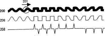
Below, with reference to Fig. 3 A and Fig. 3 B the basic skills of reproducing the information that has write down from CD of the present invention by the swing of magnetic track groove is described.
At first, with reference to Fig. 3 A and Fig. 3 B.
Fig. 3 A is the figure of the main portion of expression transcriber, and Fig. 3 B is the figure that concerns between expression magnetic track groove and the reproducing signal.
With respect to model utility be illustrated in magnetic track groove 200 among Fig. 3 B, allow the point that reproduces with laser beam 201 scan in the direction of arrows.Laser beam 201 is formed reflected light 202 by CD reflection.Reflected light 202 is received by the detecting device 203,204 of the transcriber shown in Fig. 3 A.Detecting device 203,204 with dish radial direction corresponding direction on be separated to place, export respectively corresponding to the voltage that receives light intensity.If to any side displacement of split position that is between detecting device 203 and the detecting device 204, will make between the output of the output of detecting device 203 and detecting device 204 and produce difference (differential push-pull-detection) with respect to the irradiation position (light receiving position) of the reflected light 202 of detecting device 203,204.The output of detecting device 203,204 is input in the differential circuit 205, carries out subtraction in differential circuit 205.Its result obtains the signal (swinging signal) 206 corresponding to the wobble shape of groove 200.Swinging signal 206 is input in the by-pass filter (HPF) 207, carries out differential in by-pass filter (HPF) 207.Its result, the smooth basis that is comprised in the swinging signal 206 attenuates, and obtains having the pulse signal 208 corresponding to the pulse composition of the rectangle part that orientated at steep inclinations is arranged.By Fig. 3 B as can be known, the polarity of each pulse in the pulse signal 208 depends on the direction of the precipitous displacement in the groove 200.Therefore, the lateral movement pattern that can be had according to pulse signal 208 identification slots 200.
Below, with reference to Fig. 3 C.Fig. 3 C represents the structure example by the circuit of 206 production burst signals 208 of the swinging signal shown in Fig. 3 B and clock signal 209.
In the structure example of Fig. 3 C, swinging signal 206 is input among the 1st bandpass filter BPF1 and the 2nd bandpass filter BPF2.And the 1st bandpass filter BPF1 and the 2nd bandpass filter BPF2 be production burst signal 208 and clock signal 209 respectively.
If the hunting frequency of magnetic track is made as fw (Hz), the 1st bandpass filter BPF1 is constituted by having frequency with 4fw~6fw (for example 5fw) wave filter that (transmitance) become the characteristic of peak value that will gain.According to such wave filter, from the low frequency to the crest frequency, preference rises as make gain with 20dB/dec, in the zone higher than crest frequency, preferably with rapid (for example 60dB/dec) gain is reduced.The 1st bandpass filter BPF1 can suitably generate the pulse signal 208 of the part of the swing rectangle variation of representing magnetic track according to swinging signal 206.
On the other hand, the 2nd bandpass filter BPF2 has the swing characteristic that rises, gain is diminished in given frequency band (for example being the frequency band of center, 0.5fw~1.5fw with hunting frequency fw) gain.The 2nd bandpass filter BPF2 like this can generate the sine wave signal that has with the corresponding frequency of hunting frequency of magnetic track, as clock signal 209.
Below, describe the embodiment of CD media of the present invention in detail.
(embodiment 1)
In the record surface 1 of the CD of embodiment, form such spiral fashion magnetic track groove 2 shown in Figure 1A.
Fig. 4 represents the shape of the magnetic track groove 2 in the present embodiment.Magnetic track groove 2 is divided into a plurality of message block, the field mark (identification marking) 210 that has the telltale mark function in message block and interblock setting.Field mark 210 in the present embodiment forms by magnetic track groove 2 being cut into one section one section.
As previously discussed, the difference of the waveform in the lateral movement pattern is represented with the difference of the inclination of the rising/decline of the resulting reproducing signal of differential push-pull-detection.Therefore, the lateral movement pattern that for example can be easy to recognition unit interval 22 is any in the lateral movement pattern 105 of Fig. 2 A and the lateral movement pattern 106.If, will increase the clutter composition by reproducing signal is carried out differential carry out described detection as previously discussed.Therefore, adopt under the situation of SN than low high-density CD medium, may produce the detection mistake.In order not produce such mistake, in the present embodiment, adopt the technology of following explanation.
Should be divided into a plurality of message block by the information (hereinafter referred to as ' recorded information ') that the user writes in the dish, be recorded in the recording layer along the magnetic track groove.Recorded information write be with field mark 210 be starting point, to give the message block of fixed length (for example 64 kilobyte are long) be that the unit carries out to extend along magnetic track groove 2.Such message block is the unit in the information processing, is meant for example ECC message block etc.Message block comprises N (N is a natural number) individual sub-message block (unit interval).When message block be 64 kilobyte, when sub-message block is 2 kilobyte, the number of the sub-message block that is comprised in 1 message block is exactly 32.
In the present embodiment, it is corresponding with the unit interval 22,23 of magnetic track groove to write the zone of each sub-message block information on the magnetic track groove.
Owing in unit interval 22,23, write down the secondary information 0 or 1 of 1 bit respectively, so in each message block, distribute the secondary message block of N=32 (bit).In an embodiment, the address of representing this message block by the secondary message block of this 32 bit.
For example, constituent parts length of an interval degree being set at 2418 bytes (=2048 bytes+parity check bit), 1 swing being set under the situation of the length that is equivalent to 11.625 bytes the same period, comprise 208 periodic oscillations patterns in the constituent parts interval.Its result detects the swinging signal 206 shown in Fig. 3 B and Fig. 3 C through 208 periodic quantities (208 wave number) of swinging, and can discern the kind of lateral movement pattern.Therefore, when signal reproduction, no matter, also can correctly differentiate secondary information because of clutter produces how much detect mistake.
More particularly, for example, whenever carry out rising, the decline of 1 bout, just to the maintenance of taking a sample of the differentiated waveform (pulse signal 208) of differential push-pull signal.And, if the value of totally rise respectively number of times and decline number of times is compared, owing to eliminate the clutter composition, so can extract secondary informational content accurately out.
And, be provided with owing to the field mark 210 of Fig. 4 is cut into one section one section with magnetic track groove 2, so if writing information in the recording layer on field mark 210 has just produced the problem what write.That is, owing to having or not of groove has greatly changed reflection light quantity, so the existence of field mark 210 produces interference effect to reproducing signal.So, in the present embodiment, distribute VFO (Variable Frequency Oscillator) posting field 21 comprising giving in the zone 21 of fixed length of field mark 210.So-called VFO posting field 21 is zones of record single-frequency signals VFO, and VFO is used to introduce the signal that recorded information is reproduced needed PLL.If vfo signal no matter what have disturb change, all only can produce local fluctuation, and can not produce mistake.In addition, because vfo signal is with single-frequency signal repeatedly, so interference that also can the separate information group echo.The signal that is recorded in VFO posting field 21 is not confined to single-frequency, can be the signal of specific pattern that can carry out the abundant narrow spectrum radiation frequency band of frequency separation with the signal of field mark 210 yet.
(embodiment 2)
The optical disc reproducing apparatus that explanation has the function of the address of reproducing the CD media among the embodiment 1 with reference to Fig. 5.
The laser beam irradiation CD 1 that penetrates from the shaven head 331 of this transcriber forms luminous point on the magnetic track groove of CD 1.Carry out the control of drive system, make luminous point on the magnetic track groove, move along with the rotation of CD 1.
Swinging signal is imported in the swing PLL circuit 333.Swing PLL circuit 333 generates clock signal by swinging signal, and is sent in the timing generation circuit 335.The frequency of clock signal has the size that hunting frequency is increased integral multiple.And, not under the phase locked state at swing PLL circuit 333, though the precision deterioration also can use reference clock to generate timing.
Be imported into the field mark testing circuit 334 from the full additive signal of reproducing signal treatment circuit 332 outputs.Field mark testing circuit 334 detects the position of field mark 210 from full additive signal.In the CD of embodiment 1, come from other the part height of reflector laser strength ratio of field mark 210 formed parts.Therefore, when field mark testing circuit 334 surpassed given level at full additive signal, reproducing signal treatment circuit 332 generated the field mark detection signal, and is sent in the timing generation circuit 335.
Timing generation circuit 335 calculates the clock number that starts the position from message block according to described field mark detection signal and clock signal.Can determine the grouping timing of rising timing, decline timing, secondary packets of information timing and the message block of swinging signal by this counting.
The slope that the 1st shape counting circuit 336 calculates the swinging signal when swinging signal rises in the per unit interval is set-point U
THAbove number of times.Specifically, when swinging signal rises, if the slope of push-pull signal is set-point U
THMore than, just count value C1 is increased by 1, if be lower than U
TH, keep its former state with regard to not changing count value C1.When swinging signal rises, decide by the output signal of timing generation circuit 335.
The slope that the 2nd shape counting circuit 337 calculates the swinging signal when swinging signal descends in the per unit interval is set-point D
THFollowing number of times.Specifically, when swinging signal descends, if the slope of push-pull signal is set-point D
THBelow, just count value C2 is increased by 1, if be lower than D
TH, keep its former state with regard to not changing count value C2.When swinging signal descends, decide by the output signal of timing generation circuit 335.
339 pairs of error correction circuits are allocated in the secondary message block of a plurality of unit intervals that comprised in 1 message block and implement error correction, reproduce address information.
For described each circuit, also can in a plurality of circuit, use certain circuit key element jointly, and not pattern of wants circuit independently respectively, in addition, also can be according to the program in the storer of being recorded in advance by the function of digital signal processor executive circuit.This each embodiment to the following stated also is suitable for.
(embodiment 3)
The additional embodiments of optical disc reproducing apparatus of the present invention is described with reference to Fig. 6.Optical disc reproducing apparatus in the present embodiment is compared with the optical disc reproducing apparatus among the embodiment 2, and cancellation testing circuit 340 these points are different possessing.And the function of error correction circuit 339 is also different.Except these points, the device of present embodiment is identical with the device of embodiment 2, therefore, and with regard to the common structure among not repeat specification two embodiment.
For the constituent parts interval, the count value C2 of the count value C1 of 340 pairs the 1st shape counting circuits of cancellation testing circuit, 336 outputs and 337 outputs of the 2nd shape counting circuit compares.And, for set-point E, when-E<C1-C2<+when the relation of E was set up, the differentiation of secondary information was blured, and just exports cancellation sign ' 1 '.On the other hand, when-E<C1-C2<+when the relation of E is false, just export cancellation sign ' 0 '.
When cancellation was masked as ' 1 ', error correction circuit 339 was implemented error correction forcibly with regard to the secondary information of cancellation.
In the present embodiment, because by such cancellation sign cancellation error bit, so the bit number corrected of error correction symbol is 2 times.
And, with regard to the cancellation sign, also can C1-C2 ≦-be ' 0 ' during E ,-E<C1-C2<+be ' X ' during E, when+E ≦ C1-C2, be ' 1 '.At this moment, if cancellation is masked as ' X ', also can implement error correction forcibly.
Optical disc reproducing apparatus according to above-described present embodiment, dwindle and the judgement of secondary information is under the situation of bluring in the difference of the 1st shapometer numerical value and the 2nd shapometer numerical value, in error correction procedure,, can improve error correcting capability, carry out the higher address of reliability and reproduce by this bit of cancellation.
(embodiment 4)
The address reproducting method of CD media of the present invention is described with reference to Fig. 7.
On the top of Fig. 7, be the synoptic diagram of expression wobble shape 351.The left part of wobble shape 351 is precipitous decline displacements, and left part is precipitous rising displacement.
The swinging signal 352 that is manifested in the push-pull signal does not just make quality deterioration because of clutter or waveform.
2 value signals 353 are to utilize 0 level that swinging signal 352 is carried out signal behind the amplitude limit.Differential signal 354 is that swinging signal 352 is carried out signal behind the differential.Differential signal 354 has the information of the inclination that relates to wobble shape.Even detecting beyond the part that displacement point tilts, owing to clutter or waveform are not just manifesting peaking.
In order to oversimplify, a certain part 1 arbitrarily 355 and the part 2 356 of swinging signal is described.
In the part 1 355 of swinging signal, the absolute value of the sampling value 358 of the absolute value of the sampling value 357 of the differential signal in the rising edge of 2 value signals 353 354 and the differential signal in the trailing edge 354 is compared.Because the absolute value of sampling value 358 is bigger, so the swinging signal that is comprised for part 1 355 can determine that comparing the decline displacement with the displacement of rising has precipitous lateral movement pattern.
Equally, in the part 2 356 of swinging signal, the absolute value of the sampling value 360 of the absolute value of the sampling value 359 of the differential signal in the rising edge of 2 value signals 353 354 and the differential signal in the trailing edge 354 is compared.Because the absolute value of sampling value 359 is bigger, so the swinging signal that is comprised for part 2 356 can determine that comparing the rising displacement with the displacement that descends has precipitous lateral movement pattern.
By in per hunting period, carrying out such identification, and the accumulative total recognition result, a plurality of differentiations in the secondary message unit can be carried out.
Like this,, only in edge timing, differential signal is taken a sample the signal of swinging signal 2 values with regard to address of the present invention reproducting method, and sampling value relatively.Its result detects the slope in the displacement point of wobble shape, even the interference that exists clutter or waveform just waiting also can be carried out the detection of high reliability.
(embodiment 5)
With reference to Fig. 8 explanation can be from CD of the present invention other optical disc reproducing apparatus of current address again.
Difference between the transcriber of present embodiment and the transcriber of Fig. 5 is: the device of present embodiment possesses wobble shape testing circuit 361.Wobble shape testing circuit 361 is in each hunting period, and the rising displacement of identification wobble shape is precipitous the 1st shape, or the decline displacement is the 2nd a precipitous shape, and wobble shape information is exported in the secondary information detection 338.Secondary information detection 338 is according to the wobble shape information from wobble shape circuit 361, and decision SHAPE DETECTION number is shape how.And identification has been allocated in the secondary information in the secondary message unit emphatically, and output.
Below, describe the action of wobble shape testing circuit 361 in detail with reference to Fig. 9.
Wobble shape testing circuit 361 receives push-pull signal (swinging signal), and has the BPF (bandpass filter) 362 that can reduce unwanted clutter composition.This BPF362 can make the basic wave frequency content of swinging signal and the harmonic frequency composition with slope information of swing pass through.If the basic frequency of swinging signal is set at fw, consider the variation tolerance limit of linear velocity, can preferably use bandpass filter with 1/2fw~5fw frequency band.
The output of BPF362 is imported in slope detection circuit 363 and the 2 value circuit 365.The slope of slope detection circuit 363 wobble detection signals.The detection of being somebody's turn to do ' slope ' can be by carrying out the swinging signal differential.Also can use the HPF (by-pass filter) that only extracts harmonic components out to substitute differential with slope information.The output of slope detection circuit 363 is transferred into rising value and obtains in circuit 366 and the circuit for reversing 364.
Circuit for reversing 364 makes the output of slope detection circuit 363 reverse with respect to 0 level, and outputs to drop-out value and get in the circuit 367.
The timing of rising zero crossing and the timing of decline zero passage of 2 value circuit, 365 wobble detection signals.The timing of rising zero crossing is the timing of swinging signal from ' L ' level shift to ' H ' level, and the timing of decline zero passage is the timing of swinging signal from ' H ' level shift to ' L ' level.
The slope that rising value is obtained slope detection circuit 363 output in the 365 detected rising zero crossing timing of 366 pairs 2 value circuit of the circuit maintenance of taking a sample.Equally, the drop-out value slope (counter-rotating of slope value) of obtaining circuit for reversing 364 output in the 365 detected decline zero passage timing of 367 pairs 2 value circuit of the circuit maintenance of taking a sample.
At this be slope in rising because rising value is obtained value that circuit 366 taken a sample, so be on the occasion of.And, be with the inverted value of slope in descending because drop-out value obtains the value that circuit 367 taken a sample, thus be on the occasion of.That is, rising value is obtained circuit 366 and drop-out value and is obtained the absolute value that value that circuit 367 taken a sample is equivalent to slope respectively.
In the present embodiment, same signal is inputed in 2 value circuit 365 and slope detection circuit 363 these two circuit, but the present invention is not limited to this.For the zero passage timing of wobble detection signal more accurately, also can the output of BPF362 be inputed in the 2 value circuit 365 by LPF (low-pass filter).And, as BPF362,2 kinds of BPF are arranged, can in slope detection circuit 363 and 2 value circuit 365, distribute BPF with different qualities.At this moment, in order to make the phase place unanimity of the swinging signal that passes through among each BPF, other method is preferably also to have delay compensating circuit.
Like this, according to the optical disc reproducing apparatus in the present embodiment, in the zero passage timing of the swinging signal with secondary information, sampling keeps the slope of swinging signal, and this retention value relatively.Thus, can positively carry out the identification of wobble shape, can reduce the flase drop of the secondary information that causes because of clutter and survey.
(embodiment 6)
Figure 10 represents field mark 210 is disposed at the structure of the intimate central authorities of VFO posting field 21.In the example of Figure 10, in VFO posting field 21, form the swing of square waveform, but the present invention is not limited to such mode.
At this, illustrate the method for signal record at VFO posting field 21 with reference to Figure 11 A and Figure 11 B.In Figure 11 A and Figure 11 B,, be omitted in the record of formed swing in the magnetic track groove 2 in order to oversimplify.
Figure 11 A is illustrated in the situation that writes down the signal that is equivalent to 1 message block on the magnetic track groove 2.The tracer signal of 1 message block unit comprises data (DATA) 202 and VFO201,203.
The record of each message block is from VFO201.VFO201 in the present embodiment is recorded in the VFO posting field 21, and the record start position of VFO201 is in the place ahead of field mark 210.After the record VFO201, write down the DATA202 of 1 message block amount, write down VFO203 at last.VFO203 is recorded in the VFO posting field 31, and the end of record (EOR) position of VFO203 is at the rear of field mark 310.That is, in the present embodiment, from the record of the place ahead start information of the field mark that is positioned at recording scheduled zone beginning, after the field mark that is positioned at described regional afterbody, the record of ending message.
Under the central opening entry data conditions of field mark 210,, significantly produce the deterioration of recording film in the part that has field mark 210.Owing to being cut into one section one section with magnetic track groove 2, the field mark in the present embodiment 210 is provided with, so in the part that has field mark 210, it is poor to form section on the magnetic track groove.When having the partial record information of section difference like this, and on recording film, during recorded information, need to have high-octane laser beam irradiation on recording film, give illuminated portion high heat energy.Front and back at the irradiation area of laser beam produce the big Temperature Distribution gradient.Such Temperature Distribution gradient makes recording film produce stress.There is described section difference if produce part, the worry in the little be full of cracks of generations such as recording film is then arranged at stress.If in little be full of cracks of generation such as recording films, then when writing down repeatedly, might enlarge be full of cracks, finally cause the film breakage.
In the present embodiment, in order to prevent such film breakage, the beginning/end position that writes down is placed the zone that does not have field mark 210,310.
VFO is used to adjust the false signal that data reproduction is prepared.During reproducing vfo signal, be that FEEDBACK CONTROL is carried out at the center of reproducing signal with the data slicing level, and for clock extracts out locking PLL.In order verily to reproduce data, need correctly reproduce the binaryzation and the timing of data-signal.If too short during the vfo signal, because the reproduction of beginning data under the situation of the insufficient locking of PLL, so can in the data of message block beginning, produce mistake.Therefore, preferred VFO is from the place ahead opening entry of field mark and the zone of guaranteeing abundant length.
And, in the message block of going ahead of the rest, recorded under the data conditions, shown in Figure 11 B, the VFO of the message block that will will write down now writes on the VFO of the message block of going ahead of the rest sometimes.At this moment, eliminate the part of the vfo signal that has write down.And between VFO that has existed and the VFO that writes, phase place may be asynchronous.Therefore, use the VFO of message block and the PLL that locks present message block is not good in advance.
More than, described the record start position of VFO, but the recording film deterioration is set up too for the data recording end position.But the end of record (EOR) optimum seeking site is the rear of field mark 310.If the place ahead of field mark 310 is located in the end of record (EOR) position, will form the gap in this message block and follow-up interblock sometimes.This gap is not shine the zone that high power light just can not form mark.Identical with the section difference, also there is the possibility of the deterioration that causes film in such gap.Therefore, the VFO of the message block beginning of the VFO of tail and back record carries out overlapping after the message block of preferred record earlier.Shown in Figure 11 A, the VFO record start position is set in the place ahead of field mark 210, simultaneously with VFO end of record (EOR) set positions at the rear of field mark 310, reach the overlapping of VFO thus.
Interval between the position of field mark and the VFO record start position/end position is preferably set to more than 10 times of light beam spot that write down used laser.Because beam spot diameter has the size of optical maser wavelength divided by NA value, so using under the situation of ejaculation wavelength as the optical head of the NA0.65 of the laser of 650nm, the beam spot diameter on the CD is 1 a μ m (=wavelength/NA).At this moment, preferably with the above position of range information group echo 10 μ m as start-of-record point or end point.But 10 times benchmark of so-called light beam spot can be revised by the characteristic (particularly pyroconductivity) of recording film.
When from the place ahead opening entry of field mark 210, also do not detect this field mark.Therefore,, need how to predict or the position of estimated information group echo from the place ahead opening entry of field mark for correctly.For example, can after the field mark that detects message block in advance, from described clock signal, calculate clock number, when reaching given clock number, the VFO of the message block of opening entry next time.
(embodiment 7)
With reference to Figure 12 CD media among seven embodiment is described.In described embodiment, field mark 210 is arranged at the intimate central authorities of VFO posting field 21, but in the present embodiment, as shown in figure 12, with respect to the central authorities of VFO posting field 21 and more close message block one side in advance forms field mark 211.Can guarantee the VFO that starts more by such structure.
(embodiment 8)
With reference to the CD media in Figure 13, Figure 14 A and Figure 14 B explanation present embodiment.
The field mark 210 of present embodiment is made of sub-mark 210a and sub-mark 210b.By such structure, the timing in the time of can obtaining record easily.That is, owing to form 2 marks, so can be after the mark 210b in detecting the message block the beginning part, opening entry before the certification mark 210a.And, the end that can after the 2nd mark 210a that detects the beginning part that is positioned at next message block, write down.
If like this, just do not need to calculate clock number constantly from the detection of the field mark of message block in advance, can determine record start position accurately.
For fear of the deterioration of film, preferably set fully big mark 210a and the interval between the mark 210b.Specifically, because the interval between record start position and mark 210a or the mark 210b is set at the about more than 10 times of light beam spot, so the interval between mark 210a and the mark 210b is preferably set to the about more than 20 times of light beam spot.At the light beam spot on the CD is under the situation of 1 μ m, and described interval is preferably set to more than the 20 μ m.
(embodiment 9)
With reference to Figure 15 CD in the present embodiment is described.In described embodiment, all be that magnetic track groove 2 is cut into one section one section and form field mark 210.Because such part that the magnetic track groove is interrupted does not form groove, so be smooth, is called as ' mirror mark '.Because the mirror mark is with high reflectivity reconstruction by reflection light, so be easy to detect.But do not adopt the field mark that constitutes by the mirror mark in the present embodiment, and adopt the field mark 218 of other form.Below describe field mark 218 in detail.
In the present embodiment, as shown in figure 15, in VFO posting field 21, make the swaying phase counter-rotating of magnetic track groove, the part that produces this phase reversal as field mark 218, and is had the function of field mark.
As previously discussed, the advantage that the field mark 210 that is made of the mirror mark has the bearing accuracy height, detects easily, but NA than low situation under, have the wrong problem that significantly increases that detects.In contrast, if be pre-formed the magnetic track groove, make the swaying phase counter-rotating in the front and back of field mark 218, even it is former thereby temporarily can not detect the change point (field mark 218) of swaying phase itself time because of clutter etc., by observing in advance, can detect at which and pass through field mark constantly through the swaying phase after the field mark 218.
(embodiment 10)
The other embodiment of CD of the present invention is described with reference to Figure 16.In the present embodiment, in each VFO posting field 21, form 2 field mark 218a and 218b.This field mark 218a and 218b form by the swaying phase counter-rotating that makes the magnetic track groove.
Main difference between the embodiment of present embodiment and Figure 15 is: the inverted population that are formed at the swaying phase of each interblock are odd number or even number, and this is different.As shown in figure 15, phase reversal in swing produces in each VFO posting field 21 under the situation of 1 time (odd number), produce the phase place of the later swing in the position of this phase reversal, in through this section interval before the next field mark, for the swaying phase in the message block of going ahead of the rest, always keep inverted status.Its result if will extract clock synchronously out with PLL from the swing of magnetic track groove, owing to make the reversal of poles of PLL phase bit comparison output under intact situation, produces the slip of PLL.Therefore, shown in the example of Figure 15,, just need after the process field mark, make the reversal of poles of PLL if the phase reversal number of times of swing is an odd number.
In contrast, in the present embodiment because phase place (218a) inverted once more (218b) that will counter-rotating, thus the phase place of swing turn back to again with message block in advance in the identical phase place of phase place, PLL polarity does not just need to reverse.
Interval between field mark 218a, the 218b in each VFO posting field 21 need be longer than the defective clutter of prediction.But if make this response time of being longer than PLL at interval, the incidence of described slip will be very high.As known from the above, 3~10 times of hunting frequency of being spaced apart between field mark 218a, the 218b in each VFO posting field 21 are suitable.
And the number of field mark 218a, 218b in each VFO posting field 21 is not limited to 2, so long as even number just can obtain the effect same with present embodiment.But, in limiting length range, form field mark 218a, 218b more than 4, on the viewpoint of closeness, be not good.
In the above embodiment 9 and 10, by making the swaying phase counter-rotating, can form field mark, but if the variation of energy detected phase just need just in time not rotated 90 ° in the front and back of field mark.On the position of field mark, the preferable range of the swaying phase of variation for example is 45~135 °.
(embodiment 11)
Below, with reference to Figure 17 embodiments of the invention 11 are described.
The difference of present embodiment and described embodiment is: the structure of field mark 219.The field mark 219 of present embodiment is that the swing by the frequency different with the hunting frequency of the groove that is arranged in message block inside is determined.In illustrated embodiment, the hunting frequency of field mark 219 is than the hunting frequency height of message block inside.Therefore, if, separate the identification signal different partly, just can go out the position of field mark 219 with high Precision Detection with hunting frequency by using bandpass filter to handle reproducing signal.
With regard to the CD media of present embodiment, field mark 219 is formed in the VFO posting field 21, also can write the VFO data even exist in the zone of field mark 219.
Preferably the hunting frequency of field mark 219 is set at more than 1.2 times in the scope below 3.0 of hunting frequency in the message block inside, and, more preferably more than 1.5 times in the scope below 2.0.If the hunting frequency of field mark 219 just is difficult to detect field mark 219 too near the hunting frequency of message block inside.On the other hand,,,, disturb two signals so producing owing to approach to write the signal frequency of the information of recording film if the hunting frequency of field mark 219 is compared with the hunting frequency in the message block inside when too high, and bad.
Between message block, the preferably swing of the hunting frequency same frequency in formation and the message block in the zone beyond field mark 219.The shape of the swing between the preference information group is according to the shape of the swing in the message block and difference.In example shown in Figure 17, the groove between message block crawls along sine wave curve is similar.
(embodiment 12)
Below, with reference to Figure 18 embodiments of the invention 12 are described.
In the present embodiment,, do not use amplitude or frequency or phase place to produce the shape of localized variation, will all use as field mark along the similar groove that crawls of sine wave curve as field mark.And, the swing 228,229 that the part changes frequency is set at the beginning part of each sub-message block 221,222.
Like this, by having and the beginning of the area configurations of the different hunting frequency of basic frequency of swing, can detect the boundary line between sub-message block definitely in each sub-message block.In described each embodiment, the position of sub-message block can detect by calculated the swing number by field mark, but in the present embodiment,, can confirm the position of sub-message block by detecting the sub-field mark of giving in each sub-message block (228,229).
And, the identical field mark of field mark that also can be on the appropriate location in the VFO zone 21 be adopted among formation and described each embodiment.And in the present embodiment, at the local different sub-field mark 228,229 of the beginning part formation frequency of each sub-message block 221,222, but the position of sub-field mark 228,229 also can be in the rearward end of each sub-message block.And, also can sub-field mark be set a sub-message block in odd number or even number, to substitute sub-field mark 228,229 is set in whole sub-message block.
According to the reason identical with described reason, preferably the hunting frequency of sub-field mark 228,229 is set at more than 1.2 times in the scope below 3.0 times of hunting frequency in other parts, and, more preferably be set at more than 1.5 times in the scope below 2.0 times.
Preferably use sub-field mark 228,229 for the starting position of specific sub-message block, but can also represent other information.For example, also can use a plurality of sub-field mark that is comprised in certain message block, other information perhaps, also can be write down in the address of writing down this message block or other related message block.Using a plurality of sub-field marks to come under the situation of address of recorded information group, because this address is to be recorded by the swing in the message block, so advantage is to improve the reliability that reproduce the address.
Under the situation of the information that writes down many bits by the combination of sub-message block, need the discernible difformity that 2 values are above give to sub-field mark.For the swing of different sub-field marks, both can distribute different frequencies, also can distribute different phase modulation (PM).
Below, the circuit structure that is reproduced clock signal and address information by the CD media of present embodiment is described with reference to Figure 19.
At first, by use with the direction (disk track direction) of magnetic track quadrature on the photo detector 901 and the difference arithmetic unit 371 that separate, reproduce the electric signal that comprises with the corresponding signal content of swing of groove.According to this electric signal, 374 basic cycle compositions of extracting swinging signal out of low-pass filter (LPF).The signal that only has the basic cycle composition is transferred in the clock forming circuit 373.Clock forming circuit 373 is made of for example PLL circuit etc., increases given multiple by the basic cycle signal that will receive, and generates to be used for the clock signal that the record-playback signal Synchronization is handled.
On the other hand, by-pass filter (HPF) 375 optionally makes and comprises the harmonic components that reproduces swinging signal and pass through.The steep peak composition of the saw-tooth signal that in the output of by-pass filter 375, includes the high-frequency composition of sub-field mark shown in Figure 180 228,229 or generate by the wavy swing of saw.
Sub-field mark testing circuit 337 detects the swing composition of the given frequency of sub-field mark 228,229, when detecting these marks, produces timing signal.The timing signal of output is transferred in the address decoder 378 from sub-field mark testing circuit 337.
As previously discussed, the polarity of sawing the steep peak of wavy swing is reversed according to ' 1 ' or ' 0 ' of address information.Address information testing circuit 376 detects the counter-rotating of this polarity according to the output of by-pass filter 375, and bit stream is sent in the address decoder 378.Receive the timing signal of the address decoder 378 of bit stream, reproduce address information according to output from sub-field mark testing circuit 377.
According to above embodiment, a kind of CD media can be provided, can in each message block, write the identification marking of signal by formation, and, just can carry out the information record of message block unit at an easy rate, and be suitable for densification by groove swing calculated address.And,, can alleviate the deterioration of recording film by beginning or finish apart from the abundant enterprising line item in position far away of this identification marking.
(embodiment 13)
Below, with reference to Figure 20~Figure 25 embodiments of the invention 13 are described.
In the present embodiment, local sub-field mark 238a, the 239a that increases phase information is set in each sub-message block.As the embodiment of front was illustrated, sub-field mark 238a, 239a not necessarily were used to refer in particular to the starting position of stator message block.For example, in order to improve the reliability that reproduce the address, except the swing 238b, the 239b that write down by the swing in the message block, also the information identical with swing 238b, 239b can be recorded among sub-field mark 238a, the 239a.
In the present embodiment, the sub-field mark 238a that is formed in the sub-message block 221 has the shape that is made of the non-inverted wobbles of phase place.This shape is corresponding with address information ' 1 ', and the information represented with the swing 238b in being formed at same sub-message block 221 is identical.On the other hand, the sub-field mark 239a that is formed in the sub-message block 222 has the shape that is made of the phase reversal swing.This shape is corresponding with address information ' 0 ', and the information represented with the swing 239b in being formed at same sub-message block 222 is identical.
The phase place of this a little field mark 238a, 239a is for pll clock, or homophase, or anti-phase, the address information that can obtain assisting by detected phase.
The phase place of sub-field mark 238a, 239a for example can be used structure shown in Figure 23, adopts process of heterodyning detection mode to detect.
Below, with reference to Figure 21~25 explanation method for detecting phases.
At first, if reproducing signal (for example output of the difference arithmetic unit among Figure 19 372) is set at S, as shown in figure 23, reproducing signal S is imported into by bandpass filter 501 (BPF1), by in bandpass filter 511 (BPF2) and the multiplicative operator 504.Bandpass filter 501 is extracted the swing basic frequency out from reproducing signal S, export to PLL502.PLL502 generates carrier signal (the 1st synchronizing signal C1), exports to multiplicative operator 504.
If use multiplicative operator 504 that this carrier signal C1 and reproducing signal S are multiplied each other, corresponding with the supplementary in being recorded in sub-field mark 238a, 239a with ' 1 ' or ' 0 ', and can obtain multiplying signal to the plus or minus variation.
Figure 21 represents that the supplementary of sub-field mark 238a is ' 1 ' situation, and Figure 22 represents that the supplementary of sub-field mark 239a is ' 0 ' situation.In Figure 21 and Figure 22, described multiplying signal is represented with S * C1.
Illustrate in greater detail the situation that generates multiplying signal S * C1 with reference to Figure 24.In Figure 24,2 kinds of reproducing signal S have been figured with phase reversal relation.The 1st reproducing signal S represents that with solid-line curve the 2nd reproducing signal S that differs 180 ° of phase places with it represents with dashed curve.
As shown in Figure 24, generate carrier signal C1, make itself and reproducing signal synchronous, and frequency equates with the frequency of reproducing signal S.Carrier signal C1 is the waveform that has transition between zero level (0) and the level (1) that shows certain positive voltage at voltage.Therefore, the 1st reproducing signal S that represents with solid-line curve and product S * C1 of carrier signal C1 have the waveform of representing with solid line, and the 2nd reproducing signal S that represents with dashed curve and product S * C1 of carrier signal C1 have the waveform that dots.Therefore, decide the polarity of multiplying signal S * C1 according to 2 kinds of phase places of reproducing signal.
If (S * C1) carries out the integration of given period, as Figure 21 and shown in Figure 22, puts aside positive side or minus side, becomes integrated signal (ACC) to use 505 pairs of these multiplying signals of integrator shown in Figure 23.So-called ' given period ', be equivalent to read described sub-field mark 238a or the formed interval of 239a and use up scan during.During this period, generate signal G1, and being treated to effectively of integrator 505.In other words, begin integration, finish in the decline of signal G from the rising of signal G1.
For the generation of signal G1, for example, can be with as shown in Figure 16 field mark (kind of field mark is arbitrarily) as starting point, order computation swing number will produce described signal G1 by the timing of sub-field mark.
Be recorded in the information among swing 238b, the 239b, also can adopt the detection that uses the same method.Now, suppose that bandpass filter 511 (BPF2) is that to make integer multiple frequency with the swing basic frequency among the reproducing signal S be the wave filter that the frequency band at center passes through, under the situation that makes and saw the corresponding reproducing signal S of wavy swing 238b, 239b to pass through, as Figure 21 and shown in Figure 22, can extract 2 times of harmonic signal S2 that constitute the saw ripple out.And, be ' 1 ' or ' 0 ' according to address information, that is,, can reverse and detect the phase polarity of 2 times of harmonic wave S2 according to the displacement rising displacement displacement that still descends of swing.Below, illustrate in greater detail this point with reference to Figure 25.
By Fourier expansion as can be known, swing lateral movement pattern that 238b, 239b had can be by showing with the waveform component of basic cycle vibration with the coincidence of a plurality of waveform components of periodic vibration more than 2 times.Reproducing signal S with waveform of the lateral movement pattern that reflects swing 238b, 239b can be showed by the coincidence of the basic waveform with basic frequency shown in Figure 25 with 2 times of harmonic wave S2 of 2 overtones bands of the frequency with basic waveform approx.Therefore, from reproducing signal S, remove the basic waveform composition, just can extract 2 times of harmonic wave S2 out.For the waveform of 2 times of harmonic wave S2, as shown in figure 25,2 kinds of block curve and dashed curves can be arranged.According to the lateral movement pattern of swing 238b, 239b, decide waveform, or the waveform of dashed curve of block curve.
In order to discern 2 kinds of harmonic wave S2 shown in Figure 25, can be suitable for illustrated method equally with reference to Figure 24.That is, generate carrier signal (the 2nd synchronizing signal) C2 synchronous with 2 times of harmonic wave S2 and that have the frequency identical, and multiply each other with 2 times of harmonic wave S2 with the frequency of 2 times of harmonic wave S2.If the multiplying signal S2 * 2C that obtains is like this carried out the given period integration, just can detect the information (' 1 ' or ' 0 ') that is distributed in this sub-message block.
Specifically, by multiplicative operator shown in Figure 23 512 and integrator 513, and carry out described multiplication and integration, the process of heterodyning that can carry out the address information (' 1 ' or ' 0 ') that the homophase anti-phase according to described 2 times of harmonic wave S2 forms detects.Wherein, so-called ' given period ' be meant signal G2 that supply is generated in the timing of reading photoscanning saw wavy swing 238b or 239b during.Can use the method identical to generate signal G2 with signal G1.
And, if 1/2 frequency divider 503 is set, just can obtain the carrier signal C2 of 2 times of harmonic waves from the input side of frequency divider 503 in the feedback side of PLL502.
In Figure 21 and Figure 22, represented to relate to accumulating value AS and relating to and accumulate value AM of the supplementary that obtains with described method by the address information detection signal of the wavy recorded in wobbles of saw in this message block.By using adder calculator 520 will accumulate value AS and accumulating value AM addition, can improve the SN of integrated signal ACC, its result can improve the address and obtain rate.
In Figure 21 and sprocket pulse SH shown in Figure 22, to the integrated signal ACC maintenance of taking a sample, and should value and reference value (GND) compare, can obtain address information (' 1 ' or ' 0 ') thus.The sampling of integrated signal ACC keeps and can be carried out by sampling retainer shown in Figure 23 521, can be carried out by comparer shown in Figure 23 522 with the comparison of reference value (GND).
And integrator 505,513 is reset the suitable opportunity during being High except signal G1, G2, and the ACC involution is to zero level (initial value).
In the explanation of present embodiment, the timing error of so-called ' group that is produced by bandpass filter postpones or circuit delay ' is ignored, but in the device of reality, consider the optimization that such timing error can design.
In the present embodiment,, have the different saw wave shape of inclination that rises or descend, but in general, have ' the shape difference ' of the waveform of periodic structure, can cause the amplitude of its harmonic components or the difference of phase place with the corresponding wobble shape of address information.Therefore,, just be not limited to described saw wave, also can obtain effect of the present invention if come information-recording by ' the shape difference ' of swing.But, it is generally acknowledged, because the saw wave is the waveform of the reasonable 2 subharmonic phase place marked changes of SN, so, as wobble shape, be one of optimum shape.
In the present embodiment, employing is carried out being undertaken by adder calculator 520 after the Integral Processing, again the structure of addition respectively by integrator 505,513, because integrator is exactly to accumulate adder calculator originally, so also can replace adder calculator 502 with in the integrator any one.For example, if make in advance, just can functionally realize the structure of integrator 505,513 and adder calculator 520 through each the electric current output in the multiplicative operator 504,512 and to 1 capacitor charging.
Energy detected phase information in the present embodiment, is equivalent to detect the phase place of address information, and used multiplicative operator 504,512, if also can be used multiplicative operator element in addition.For example, can adopt the such logic element of EXOR circuit that can in circuit such as PLL, use to carry out the phase-detection of address information.
According to the present invention, be used for sub-field mark (sub-field mark) owing in a plurality of sub-message block (unit interval part) of arranging, be provided with respectively, so can detect sub-message block at an easy rate along the magnetic track groove.Particularly, represent under the situation of the information identical being used for sub-field mark, reliably the represented information of the shape of crawling of read track groove with the represented information (' 1 ' or ' 0 ') of the shape of crawling of the magnetic track groove of each sub-message block.
Claims (8)
1, a kind of CD media has the magnetic track groove, along described magnetic track groove recorded information,
Described magnetic track groove comprises: along a plurality of unit intervals part that described magnetic track groove is arranged, promptly have along described magnetic track groove a plurality of unit intervals part of the side of displacement periodically;
The side of described a plurality of unit intervals part utilizes the shape of distributing to the constituent parts segment part to come the secondary information of performance point dispensing constituent parts segment part;
The constituent parts segment part has:
Be defined as precipitous relatively, the 1st mild relatively side displacement pattern that descends of rising of signal waveform, perhaps
Be defined as mild relatively, the 2nd precipitous relatively side displacement pattern of decline of rising of signal waveform;
The identification marking that is used for the constituent parts segment part is configured in the beginning of corresponding unit interval part;
Described identification marking has and the described the 1st and the 2nd other side displacement pattern of side displacement pattern area, and, show and the identical information of secondary information that shape showed of distributing to corresponding unit interval part.
2, CD media according to claim 1 is characterized in that:
Carry out record along the information of described magnetic track groove record with the message block unit of given length;
Each message block comprises N the unit interval part of arranging along described magnetic track groove.
3, CD media according to claim 1 is characterized in that:
The side displacement of described magnetic track groove is with respect to center line all sides or outer circumferential side in dish of described magnetic track groove.
4, CD media according to claim 2 is characterized in that:
The cycle of the side displacement pattern of described a plurality of unit intervals has certain value at least in 1 message block.
5, according to any described CD media in the claim 1~4, it is characterized in that:
The secondary information of the constituent parts segment part being distributed 1 bit;
In N the unit interval part that each message block comprised, writing down the secondary message block of N bit.
6, CD media according to claim 5 is characterized in that:
The secondary message block of described N bit comprises: the address information that is writing down the message block under the unit interval part of described secondary message block.
7, a kind of accessory rights requires to reproduce in the 6 described CD media method of address information, comprising:
Detect identification marking, generate the step (a) of corresponding the 1st signal of information that shows with described identification marking;
The step (b) of corresponding the 2nd signal of secondary information of the unit interval part performance of the generation and the described identification marking that continues;
Decide the step (c) of the described secondary information of described unit interval part performance according to described the 1st signal and described the 2nd signal.
8, a kind of energy accessory rights requires to reproduce in the 6 described CD media device of address information, comprising:
Detect identification marking, generate the device of corresponding the 1st signal of information that shows with described identification marking;
The device of corresponding the 2nd signal of secondary information of the unit interval part performance of the generation and the described identification marking that continues;
Decide the device of the described secondary information of described unit interval part performance according to described the 1st signal and described the 2nd signal.
Applications Claiming Priority (6)
| Application Number | Priority Date | Filing Date | Title |
|---|---|---|---|
| JP2001185729 | 2001-06-20 | ||
| JP2001185729 | 2001-06-20 | ||
| JP2001212071 | 2001-07-12 | ||
| JP2001212071 | 2001-07-12 | ||
| JP2001348306 | 2001-11-14 | ||
| JP2001348306 | 2001-11-14 |
Related Parent Applications (1)
| Application Number | Title | Priority Date | Filing Date |
|---|---|---|---|
| CNB021248273A Division CN1280790C (en) | 2001-06-20 | 2002-06-20 | Optical disc medium, information reproducing method and device |
Publications (2)
| Publication Number | Publication Date |
|---|---|
| CN1975871A CN1975871A (en) | 2007-06-06 |
| CN100468530C true CN100468530C (en) | 2009-03-11 |
Family
ID=27346981
Family Applications (2)
| Application Number | Title | Priority Date | Filing Date |
|---|---|---|---|
| CNB021248273A Expired - Fee Related CN1280790C (en) | 2001-06-20 | 2002-06-20 | Optical disc medium, information reproducing method and device |
| CNB2006101388109A Expired - Fee Related CN100468530C (en) | 2001-06-20 | 2002-06-20 | Optical disk medium and method and apparatus for reproducing information |
Family Applications Before (1)
| Application Number | Title | Priority Date | Filing Date |
|---|---|---|---|
| CNB021248273A Expired - Fee Related CN1280790C (en) | 2001-06-20 | 2002-06-20 | Optical disc medium, information reproducing method and device |
Country Status (7)
| Country | Link |
|---|---|
| US (7) | US6724708B2 (en) |
| EP (3) | EP1473730B1 (en) |
| JP (1) | JP4406665B2 (en) |
| KR (3) | KR100868827B1 (en) |
| CN (2) | CN1280790C (en) |
| DE (2) | DE60213877T2 (en) |
| HK (1) | HK1105544A1 (en) |
Families Citing this family (21)
| Publication number | Priority date | Publication date | Assignee | Title |
|---|---|---|---|---|
| EP2315208B1 (en) * | 2000-09-01 | 2013-07-17 | Panasonic Corporation | Optical disc medium, optical disc playback and recorder |
| KR100798193B1 (en) * | 2000-10-03 | 2008-01-24 | 마츠시타 덴끼 산교 가부시키가이샤 | Multi-layer optical disk and method of producing multi-layer optical disk |
| US6724708B2 (en) * | 2001-06-20 | 2004-04-20 | Matsushita Electric Industrial Co., Ltd. | Optical disk medium and method and apparatus for reading information |
| JP4121265B2 (en) * | 2001-10-16 | 2008-07-23 | コーニンクレッカ フィリップス エレクトロニクス エヌ ヴィ | Disc-shaped recording medium, disc drive apparatus, disc manufacturing apparatus and method |
| CN1229782C (en) * | 2001-11-21 | 2005-11-30 | 松下电器产业株式会社 | Reproducing method and device |
| US7376056B2 (en) * | 2002-01-21 | 2008-05-20 | Matsushita Electric Industrial Co., Ltd. | Method and apparatus for reading address information from an optical disc medium |
| JP2004134002A (en) * | 2002-10-10 | 2004-04-30 | Sony Corp | Disk drive device, prepit detecting method |
| JP2006526232A (en) * | 2003-05-27 | 2006-11-16 | コーニンクレッカ フィリップス エレクトロニクス エヌ ヴィ | Bit synchronization detection means |
| JP4095493B2 (en) * | 2003-05-30 | 2008-06-04 | 株式会社東芝 | Optical disc apparatus and optical disc processing method |
| EP1511019B1 (en) * | 2003-08-25 | 2006-07-26 | Thomson Licensing | Wobble demodulation for high density optical recording media |
| EP1511018A1 (en) | 2003-08-25 | 2005-03-02 | Deutsche Thomson-Brandt Gmbh | Wobble demodulation for high density optical recording media |
| JP3597189B1 (en) * | 2003-10-09 | 2004-12-02 | 株式会社リコー | Wobble signal demodulation method, wobble signal demodulation circuit, and optical disk device |
| JP2005158168A (en) * | 2003-11-27 | 2005-06-16 | Pioneer Electronic Corp | Information reading device and prepit detecting circuit |
| KR100615617B1 (en) * | 2004-12-17 | 2006-08-25 | 삼성전자주식회사 | Apparatus for detecting Saw-Tooth Wobbles from optical disc and method thereof |
| KR100739749B1 (en) * | 2005-11-03 | 2007-07-13 | 삼성전자주식회사 | Method and apparatus for detecting saw tooth wobble signal |
| CN101536096B (en) * | 2006-11-16 | 2011-11-16 | 松下电器产业株式会社 | Optical information reproducing device tracking apparatus |
| JP4696095B2 (en) * | 2007-06-29 | 2011-06-08 | パナソニック株式会社 | Information recording apparatus and information recording method |
| JP2009104686A (en) * | 2007-10-22 | 2009-05-14 | Hitachi Ltd | Optical disk medium, information recording method, and optical disk drive |
| US7830753B2 (en) * | 2007-11-20 | 2010-11-09 | Panasonic Corporation | Optical disc, optical disc drive, optical disc recording/reproducing method, and integrated circuit |
| US7821910B2 (en) * | 2007-11-20 | 2010-10-26 | Panasonic Corporation | Optical disc, optical disc drive, optical disc recording/reproducing method, and integrated circuit |
| JP5824660B2 (en) * | 2010-07-12 | 2015-11-25 | パナソニックIpマネジメント株式会社 | Phase shift detection device, motor drive device, brushless motor, and phase shift detection method |
Family Cites Families (40)
| Publication number | Priority date | Publication date | Assignee | Title |
|---|---|---|---|---|
| DE3780517T2 (en) | 1986-05-31 | 1993-03-25 | Sony Corp | METHODS AND DEVICE FOR SEARCHING A DESTINATION ADDRESS ON A RECORDING MEDIUM. |
| EP0286326B1 (en) * | 1987-04-08 | 1994-06-15 | Nippon Telegraph and Telephone Corporation | Method and apparatus for fabricating an optical disc master and an optical disc |
| NL8800151A (en) | 1988-01-22 | 1989-08-16 | Philips Nv | METHOD AND APPARATUS FOR RECORDING AN INFORMATION SIGNAL |
| JP2869146B2 (en) | 1990-06-15 | 1999-03-10 | パイオニア株式会社 | Optical information recording medium |
| DE69230168T2 (en) | 1991-12-02 | 2000-04-20 | Koninkl Philips Electronics Nv | Closed information system with copy protection |
| JP2854187B2 (en) | 1992-05-12 | 1999-02-03 | シャープ株式会社 | Optical recording medium and information recording / reproducing device |
| JP2677122B2 (en) | 1992-06-04 | 1997-11-17 | ソニー株式会社 | Writable optical disc |
| JPH0652639A (en) * | 1992-07-29 | 1994-02-25 | Matsushita Electric Ind Co Ltd | Information recording medium and tracking error detection device |
| JP3511650B2 (en) | 1993-09-30 | 2004-03-29 | ソニー株式会社 | Track address playback device |
| JP3511664B2 (en) | 1994-02-28 | 2004-03-29 | ソニー株式会社 | Track address reproducing method and apparatus |
| JPH0845246A (en) * | 1994-07-29 | 1996-02-16 | Sony Corp | Recording medium, reproducing method, recording device and reproducing device |
| JP3446914B2 (en) | 1995-06-02 | 2003-09-16 | ソニー株式会社 | Data recording disk, data recording apparatus and method |
| US5835478A (en) | 1995-06-15 | 1998-11-10 | Sony Corporation | Optical disc having address information for recording and reproducing data at correct positions |
| JP3426809B2 (en) * | 1995-10-13 | 2003-07-14 | 株式会社東芝 | Disk cartridge device |
| JP3850060B2 (en) * | 1996-02-13 | 2006-11-29 | 三菱電機株式会社 | Optical disc and optical disc apparatus |
| JPH09259440A (en) * | 1996-03-25 | 1997-10-03 | Sony Corp | Recording medium, address recording method and device therefor, and recording and reproducing method and device therefor |
| JP3703569B2 (en) * | 1996-04-02 | 2005-10-05 | ソニー株式会社 | Optical recording medium, recording / reproducing method thereof, and recording / reproducing apparatus |
| JP3379961B2 (en) * | 1996-04-05 | 2003-02-24 | 松下電器産業株式会社 | Recording medium in which audio data and sub-picture data of a plurality of channels are recorded together with moving image data, reproducing apparatus and reproducing method thereof |
| JPH09297921A (en) * | 1996-05-08 | 1997-11-18 | Ricoh Co Ltd | Phase transition type optical recording medium |
| JPH09314538A (en) | 1996-05-28 | 1997-12-09 | Kunimine Kogyo Kk | Preparation of paste containing clay |
| JPH09326139A (en) | 1996-06-06 | 1997-12-16 | Victor Co Of Japan Ltd | Production of phase transition type optical disk |
| JPH103667A (en) | 1996-06-13 | 1998-01-06 | Sony Corp | Recording and reproducing device and its method, and disk |
| KR100215705B1 (en) * | 1996-11-02 | 1999-08-16 | 구자홍 | Method for recording information without damaging before hand recorded information |
| KR100254610B1 (en) * | 1997-01-06 | 2000-05-01 | 구자홍 | Apparatus and method for calculating reproducing time of optical disc |
| JP3148673B2 (en) | 1997-03-27 | 2001-03-19 | 三洋電機株式会社 | Reference mark detection circuit |
| US6377528B1 (en) * | 1997-03-25 | 2002-04-23 | Sanyo Electric Co., Ltd. | Information reproducer, information recorder and reference mark detection circuit |
| US6118741A (en) * | 1997-06-19 | 2000-09-12 | Mimnagh; Winslow M. | Method and device for recording information on a carrier |
| JPH1196604A (en) | 1997-07-24 | 1999-04-09 | Sony Corp | Optical recording medium, and manufacture of optical recording medium |
| JP3546654B2 (en) * | 1997-08-07 | 2004-07-28 | 株式会社日立製作所 | Information recording apparatus and information recording method |
| JP3488603B2 (en) * | 1997-09-16 | 2004-01-19 | 株式会社東芝 | Copy protection system using digital watermark |
| DE69833976T2 (en) * | 1997-09-17 | 2006-09-07 | Matsushita Electric Industrial Co., Ltd., Kadoma | Optical disc, recording device, and computer-readable recording medium |
| EP0926664B1 (en) * | 1997-12-26 | 2006-05-31 | Kabushiki Kaisha Toshiba | Optical disk and optical disk apparatus |
| JP3597689B2 (en) * | 1998-01-21 | 2004-12-08 | 株式会社東芝 | Information recording medium and information recording medium processing device |
| WO1999048092A2 (en) * | 1998-03-16 | 1999-09-23 | Koninklijke Philips Electronics N.V. | Optical record carrier |
| JPH11283280A (en) | 1998-03-30 | 1999-10-15 | Victor Co Of Japan Ltd | Optical disk, device and method for recording and reproducing optical disk, and device for producing master disk of optical disk |
| EP1066628B1 (en) | 1999-01-25 | 2003-11-12 | Koninklijke Philips Electronics N.V. | Record carrier and apparatus for scanning the record carrier |
| TW468171B (en) | 1999-06-02 | 2001-12-11 | Koninkl Philips Electronics Nv | Optical record carrier |
| AU2001282543B2 (en) | 2000-08-31 | 2005-03-17 | Matsushita Electric Industrial Co., Ltd. | Optical disc and physical address format |
| EP2315208B1 (en) * | 2000-09-01 | 2013-07-17 | Panasonic Corporation | Optical disc medium, optical disc playback and recorder |
| US6724708B2 (en) * | 2001-06-20 | 2004-04-20 | Matsushita Electric Industrial Co., Ltd. | Optical disk medium and method and apparatus for reading information |
-
2002
- 2002-06-17 US US10/173,903 patent/US6724708B2/en not_active Expired - Lifetime
- 2002-06-19 KR KR1020020034250A patent/KR100868827B1/en active IP Right Grant
- 2002-06-20 EP EP04018603A patent/EP1473730B1/en not_active Expired - Fee Related
- 2002-06-20 CN CNB021248273A patent/CN1280790C/en not_active Expired - Fee Related
- 2002-06-20 CN CNB2006101388109A patent/CN100468530C/en not_active Expired - Fee Related
- 2002-06-20 EP EP02013737A patent/EP1271489B1/en not_active Expired - Fee Related
- 2002-06-20 EP EP06008834A patent/EP1686587B1/en not_active Expired - Lifetime
- 2002-06-20 DE DE60213877T patent/DE60213877T2/en not_active Expired - Lifetime
- 2002-06-20 DE DE60202020T patent/DE60202020T2/en not_active Expired - Lifetime
-
2004
- 2004-03-09 US US10/796,874 patent/US7116630B2/en not_active Expired - Lifetime
-
2005
- 2005-11-02 US US11/265,688 patent/US7362664B2/en not_active Expired - Fee Related
-
2006
- 2006-04-07 US US11/279,040 patent/US7474606B2/en not_active Expired - Fee Related
- 2006-08-03 US US11/462,058 patent/US7474607B2/en not_active Expired - Fee Related
-
2007
- 2007-12-03 HK HK07113192.2A patent/HK1105544A1/en not_active IP Right Cessation
-
2008
- 2008-01-16 US US12/015,081 patent/US20080117803A1/en not_active Abandoned
- 2008-02-07 JP JP2008028034A patent/JP4406665B2/en not_active Expired - Lifetime
- 2008-05-26 KR KR1020080048851A patent/KR100887037B1/en active IP Right Grant
- 2008-05-26 KR KR1020080048852A patent/KR100892481B1/en active IP Right Grant
-
2009
- 2009-06-22 US US12/488,794 patent/US7933170B2/en not_active Expired - Fee Related
Also Published As
Similar Documents
| Publication | Publication Date | Title |
|---|---|---|
| CN100468530C (en) | Optical disk medium and method and apparatus for reproducing information | |
| CN1534625B (en) | Light disk medium, light disk reproducing method and storage method | |
| US4901300A (en) | Method of and apparatus for recording an information signal | |
| US20060182013A1 (en) | Optical disc and physical address format | |
| PL197778B1 (en) | Record carrier and apparatus for scanning the record carrier | |
| US4807214A (en) | Apparatus for recording and/or reading information on an optical record carrier provided with preformed tracks | |
| US4949325A (en) | Method and associated apparatus and medium for optical recording and reproducing information | |
| JP2807362B2 (en) | Information playback device | |
| US7016284B2 (en) | Method and related circuit for generating a wobble clock and an ATIP clock through a reference clock and a wobble signal | |
| CN103562998A (en) | Optical disk recording medium, optical disk device, and recording method | |
| CN1636244B (en) | Recording apparatus, recording method | |
| JP3051016B2 (en) | Optical disk medium and clock generation device therefor | |
| CN103971714A (en) | Information recording medium, information reproducing method, and information reproducing apparatus | |
| US20030133375A1 (en) | Information storage medium, information recording apparatus, and information playback apparatus | |
| EP0898271A2 (en) | Optical record carrier and apparatus for recording and reproduction of optical record carrier | |
| JP4794260B2 (en) | Disc player | |
| CN100446091C (en) | Optical disk medium, optical disk reproducing device and storage device | |
| JP2002208231A (en) | Pll device for information recording and reproducing device | |
| CN101093676B (en) | Optical disk recording device | |
| JP2004273095A (en) | Recording medium, wobble cycle detecting method, wobble information detecting method, wobble information detecting circuit, and information recording and reproducing device | |
| KR19990038763A (en) | Method and device for recording media | |
| JP2003217132A (en) | Optical disk medium, and method and device for reproducing information | |
| JPH08315367A (en) | Information recording/reproducing device |
Legal Events
| Date | Code | Title | Description |
|---|---|---|---|
| C06 | Publication | ||
| PB01 | Publication | ||
| C10 | Entry into substantive examination | ||
| SE01 | Entry into force of request for substantive examination | ||
| REG | Reference to a national code |
Ref country code: HK Ref legal event code: DE Ref document number: 1105544 Country of ref document: HK |
|
| C14 | Grant of patent or utility model | ||
| GR01 | Patent grant | ||
| REG | Reference to a national code |
Ref country code: HK Ref legal event code: GR Ref document number: 1105544 Country of ref document: HK |
|
| CF01 | Termination of patent right due to non-payment of annual fee |
Granted publication date: 20090311 Termination date: 20200620 |
|
| CF01 | Termination of patent right due to non-payment of annual fee |