CN100558320C - Intracavity stent with intercolumniation interconnecting members - Google Patents
Intracavity stent with intercolumniation interconnecting members Download PDFInfo
- Publication number
- CN100558320C CN100558320C CNB2004800129661A CN200480012966A CN100558320C CN 100558320 C CN100558320 C CN 100558320C CN B2004800129661 A CNB2004800129661 A CN B2004800129661A CN 200480012966 A CN200480012966 A CN 200480012966A CN 100558320 C CN100558320 C CN 100558320C
- Authority
- CN
- China
- Prior art keywords
- interconnecting members
- intracavity stent
- expansion elements
- adjacent circumferential
- circumferential expansion
- Prior art date
- Legal status (The legal status is an assumption and is not a legal conclusion. Google has not performed a legal analysis and makes no representation as to the accuracy of the status listed.)
- Expired - Lifetime
Links
- 230000008572 axis elongation Effects 0.000 claims 2
- 239000000463 material Substances 0.000 description 52
- 238000000034 method Methods 0.000 description 23
- 238000000151 deposition Methods 0.000 description 17
- 239000000758 substrate Substances 0.000 description 17
- 230000007797 corrosion Effects 0.000 description 16
- 238000005260 corrosion Methods 0.000 description 16
- 230000008021 deposition Effects 0.000 description 15
- 229910001000 nickel titanium Inorganic materials 0.000 description 14
- 238000013461 design Methods 0.000 description 11
- 229910045601 alloy Inorganic materials 0.000 description 10
- 239000000956 alloy Substances 0.000 description 10
- 239000007943 implant Substances 0.000 description 10
- 238000004519 manufacturing process Methods 0.000 description 10
- PXHVJJICTQNCMI-UHFFFAOYSA-N Nickel Chemical compound [Ni] PXHVJJICTQNCMI-UHFFFAOYSA-N 0.000 description 8
- KHYBPSFKEHXSLX-UHFFFAOYSA-N iminotitanium Chemical compound [Ti]=N KHYBPSFKEHXSLX-UHFFFAOYSA-N 0.000 description 8
- 238000010276 construction Methods 0.000 description 6
- 230000032798 delamination Effects 0.000 description 6
- 238000005516 engineering process Methods 0.000 description 6
- 239000010410 layer Substances 0.000 description 6
- 238000004904 shortening Methods 0.000 description 6
- 238000007740 vapor deposition Methods 0.000 description 6
- XKRFYHLGVUSROY-UHFFFAOYSA-N Argon Chemical compound [Ar] XKRFYHLGVUSROY-UHFFFAOYSA-N 0.000 description 5
- 230000006399 behavior Effects 0.000 description 5
- 238000005137 deposition process Methods 0.000 description 5
- 239000007789 gas Substances 0.000 description 5
- 229910052751 metal Inorganic materials 0.000 description 5
- 239000002184 metal Substances 0.000 description 5
- HLXZNVUGXRDIFK-UHFFFAOYSA-N nickel titanium Chemical compound [Ti].[Ti].[Ti].[Ti].[Ti].[Ti].[Ti].[Ti].[Ti].[Ti].[Ti].[Ni].[Ni].[Ni].[Ni].[Ni].[Ni].[Ni].[Ni].[Ni].[Ni].[Ni].[Ni].[Ni].[Ni] HLXZNVUGXRDIFK-UHFFFAOYSA-N 0.000 description 5
- 230000005855 radiation Effects 0.000 description 5
- 239000000126 substance Substances 0.000 description 5
- IJGRMHOSHXDMSA-UHFFFAOYSA-N Atomic nitrogen Chemical compound N#N IJGRMHOSHXDMSA-UHFFFAOYSA-N 0.000 description 4
- KDLHZDBZIXYQEI-UHFFFAOYSA-N Palladium Chemical compound [Pd] KDLHZDBZIXYQEI-UHFFFAOYSA-N 0.000 description 4
- 229910000831 Steel Inorganic materials 0.000 description 4
- 239000013078 crystal Substances 0.000 description 4
- 238000005530 etching Methods 0.000 description 4
- 230000000004 hemodynamic effect Effects 0.000 description 4
- 238000001000 micrograph Methods 0.000 description 4
- 239000000203 mixture Substances 0.000 description 4
- 229910052759 nickel Inorganic materials 0.000 description 4
- BASFCYQUMIYNBI-UHFFFAOYSA-N platinum Chemical compound [Pt] BASFCYQUMIYNBI-UHFFFAOYSA-N 0.000 description 4
- 239000002244 precipitate Substances 0.000 description 4
- 239000000047 product Substances 0.000 description 4
- 239000010959 steel Substances 0.000 description 4
- 229910052782 aluminium Inorganic materials 0.000 description 3
- XAGFODPZIPBFFR-UHFFFAOYSA-N aluminium Chemical compound [Al] XAGFODPZIPBFFR-UHFFFAOYSA-N 0.000 description 3
- 229910052786 argon Inorganic materials 0.000 description 3
- 230000008901 benefit Effects 0.000 description 3
- 239000000560 biocompatible material Substances 0.000 description 3
- 230000008859 change Effects 0.000 description 3
- 230000008602 contraction Effects 0.000 description 3
- 238000002347 injection Methods 0.000 description 3
- 239000007924 injection Substances 0.000 description 3
- 238000010884 ion-beam technique Methods 0.000 description 3
- 229910052756 noble gas Inorganic materials 0.000 description 3
- 239000011148 porous material Substances 0.000 description 3
- 238000001556 precipitation Methods 0.000 description 3
- 238000005507 spraying Methods 0.000 description 3
- 238000001771 vacuum deposition Methods 0.000 description 3
- VYZAMTAEIAYCRO-UHFFFAOYSA-N Chromium Chemical compound [Cr] VYZAMTAEIAYCRO-UHFFFAOYSA-N 0.000 description 2
- FYYHWMGAXLPEAU-UHFFFAOYSA-N Magnesium Chemical compound [Mg] FYYHWMGAXLPEAU-UHFFFAOYSA-N 0.000 description 2
- ZOKXTWBITQBERF-UHFFFAOYSA-N Molybdenum Chemical compound [Mo] ZOKXTWBITQBERF-UHFFFAOYSA-N 0.000 description 2
- XUIMIQQOPSSXEZ-UHFFFAOYSA-N Silicon Chemical compound [Si] XUIMIQQOPSSXEZ-UHFFFAOYSA-N 0.000 description 2
- BQCADISMDOOEFD-UHFFFAOYSA-N Silver Chemical compound [Ag] BQCADISMDOOEFD-UHFFFAOYSA-N 0.000 description 2
- RTAQQCXQSZGOHL-UHFFFAOYSA-N Titanium Chemical compound [Ti] RTAQQCXQSZGOHL-UHFFFAOYSA-N 0.000 description 2
- QCWXUUIWCKQGHC-UHFFFAOYSA-N Zirconium Chemical compound [Zr] QCWXUUIWCKQGHC-UHFFFAOYSA-N 0.000 description 2
- 238000000137 annealing Methods 0.000 description 2
- 230000015572 biosynthetic process Effects 0.000 description 2
- 230000017531 blood circulation Effects 0.000 description 2
- 210000004204 blood vessel Anatomy 0.000 description 2
- 230000036760 body temperature Effects 0.000 description 2
- 238000006243 chemical reaction Methods 0.000 description 2
- 229910052804 chromium Inorganic materials 0.000 description 2
- 239000011651 chromium Substances 0.000 description 2
- 239000011248 coating agent Substances 0.000 description 2
- 238000000576 coating method Methods 0.000 description 2
- 229910017052 cobalt Inorganic materials 0.000 description 2
- 239000010941 cobalt Substances 0.000 description 2
- GUTLYIVDDKVIGB-UHFFFAOYSA-N cobalt atom Chemical compound [Co] GUTLYIVDDKVIGB-UHFFFAOYSA-N 0.000 description 2
- 230000006835 compression Effects 0.000 description 2
- 238000007906 compression Methods 0.000 description 2
- 230000000694 effects Effects 0.000 description 2
- 210000003038 endothelium Anatomy 0.000 description 2
- 230000006870 function Effects 0.000 description 2
- PCHJSUWPFVWCPO-UHFFFAOYSA-N gold Chemical compound [Au] PCHJSUWPFVWCPO-UHFFFAOYSA-N 0.000 description 2
- 229910052737 gold Inorganic materials 0.000 description 2
- 239000010931 gold Substances 0.000 description 2
- 230000035876 healing Effects 0.000 description 2
- 230000036541 health Effects 0.000 description 2
- 230000001788 irregular Effects 0.000 description 2
- 238000003754 machining Methods 0.000 description 2
- 229910052749 magnesium Inorganic materials 0.000 description 2
- 239000011777 magnesium Substances 0.000 description 2
- WPBNNNQJVZRUHP-UHFFFAOYSA-L manganese(2+);methyl n-[[2-(methoxycarbonylcarbamothioylamino)phenyl]carbamothioyl]carbamate;n-[2-(sulfidocarbothioylamino)ethyl]carbamodithioate Chemical compound [Mn+2].[S-]C(=S)NCCNC([S-])=S.COC(=O)NC(=S)NC1=CC=CC=C1NC(=S)NC(=O)OC WPBNNNQJVZRUHP-UHFFFAOYSA-L 0.000 description 2
- 229910001092 metal group alloy Inorganic materials 0.000 description 2
- 238000004377 microelectronic Methods 0.000 description 2
- 229910052750 molybdenum Inorganic materials 0.000 description 2
- 239000011733 molybdenum Substances 0.000 description 2
- 229910052758 niobium Inorganic materials 0.000 description 2
- 239000010955 niobium Substances 0.000 description 2
- GUCVJGMIXFAOAE-UHFFFAOYSA-N niobium atom Chemical compound [Nb] GUCVJGMIXFAOAE-UHFFFAOYSA-N 0.000 description 2
- 229910052757 nitrogen Inorganic materials 0.000 description 2
- 229910052763 palladium Inorganic materials 0.000 description 2
- 238000005240 physical vapour deposition Methods 0.000 description 2
- 229910052697 platinum Inorganic materials 0.000 description 2
- 230000008569 process Effects 0.000 description 2
- 238000012545 processing Methods 0.000 description 2
- 229910052706 scandium Inorganic materials 0.000 description 2
- SIXSYDAISGFNSX-UHFFFAOYSA-N scandium atom Chemical compound [Sc] SIXSYDAISGFNSX-UHFFFAOYSA-N 0.000 description 2
- 238000004062 sedimentation Methods 0.000 description 2
- 229910052710 silicon Inorganic materials 0.000 description 2
- 239000010703 silicon Substances 0.000 description 2
- 229910052709 silver Inorganic materials 0.000 description 2
- 239000004332 silver Substances 0.000 description 2
- 229910052715 tantalum Inorganic materials 0.000 description 2
- GUVRBAGPIYLISA-UHFFFAOYSA-N tantalum atom Chemical compound [Ta] GUVRBAGPIYLISA-UHFFFAOYSA-N 0.000 description 2
- 229910052719 titanium Inorganic materials 0.000 description 2
- 239000010936 titanium Substances 0.000 description 2
- 238000012546 transfer Methods 0.000 description 2
- 229910052720 vanadium Inorganic materials 0.000 description 2
- LEONUFNNVUYDNQ-UHFFFAOYSA-N vanadium atom Chemical compound [V] LEONUFNNVUYDNQ-UHFFFAOYSA-N 0.000 description 2
- 229910052726 zirconium Inorganic materials 0.000 description 2
- OKTJSMMVPCPJKN-UHFFFAOYSA-N Carbon Chemical compound [C] OKTJSMMVPCPJKN-UHFFFAOYSA-N 0.000 description 1
- OAICVXFJPJFONN-UHFFFAOYSA-N Phosphorus Chemical compound [P] OAICVXFJPJFONN-UHFFFAOYSA-N 0.000 description 1
- 229910001362 Ta alloys Inorganic materials 0.000 description 1
- 230000001133 acceleration Effects 0.000 description 1
- 230000003321 amplification Effects 0.000 description 1
- 238000013459 approach Methods 0.000 description 1
- -1 argon ion Chemical class 0.000 description 1
- 229910052799 carbon Inorganic materials 0.000 description 1
- 238000003486 chemical etching Methods 0.000 description 1
- 230000004087 circulation Effects 0.000 description 1
- 230000007547 defect Effects 0.000 description 1
- 230000002950 deficient Effects 0.000 description 1
- 230000004069 differentiation Effects 0.000 description 1
- 230000009977 dual effect Effects 0.000 description 1
- 239000000428 dust Substances 0.000 description 1
- 230000005611 electricity Effects 0.000 description 1
- 238000005566 electron beam evaporation Methods 0.000 description 1
- 239000012530 fluid Substances 0.000 description 1
- 238000002513 implantation Methods 0.000 description 1
- 230000006872 improvement Effects 0.000 description 1
- 239000012535 impurity Substances 0.000 description 1
- 239000011229 interlayer Substances 0.000 description 1
- 150000002500 ions Chemical class 0.000 description 1
- 238000000608 laser ablation Methods 0.000 description 1
- 239000012528 membrane Substances 0.000 description 1
- 229910052754 neon Inorganic materials 0.000 description 1
- GKAOGPIIYCISHV-UHFFFAOYSA-N neon atom Chemical compound [Ne] GKAOGPIIYCISHV-UHFFFAOYSA-N 0.000 description 1
- 238000003199 nucleic acid amplification method Methods 0.000 description 1
- 229910052698 phosphorus Inorganic materials 0.000 description 1
- 239000011574 phosphorus Substances 0.000 description 1
- 230000035479 physiological effects, processes and functions Effects 0.000 description 1
- 102000004169 proteins and genes Human genes 0.000 description 1
- 108090000623 proteins and genes Proteins 0.000 description 1
- 238000010791 quenching Methods 0.000 description 1
- 230000000171 quenching effect Effects 0.000 description 1
- 230000011514 reflex Effects 0.000 description 1
- 230000002787 reinforcement Effects 0.000 description 1
- 239000007787 solid Substances 0.000 description 1
- 239000007921 spray Substances 0.000 description 1
- 239000010935 stainless steel Substances 0.000 description 1
- 229910001220 stainless steel Inorganic materials 0.000 description 1
- 230000001360 synchronised effect Effects 0.000 description 1
- WILOFBYLLUPEHC-UHFFFAOYSA-N tantalum titanium zirconium Chemical compound [Ti].[Zr].[Ta] WILOFBYLLUPEHC-UHFFFAOYSA-N 0.000 description 1
- 238000012360 testing method Methods 0.000 description 1
- 210000001519 tissue Anatomy 0.000 description 1
- 230000007704 transition Effects 0.000 description 1
- 238000005019 vapor deposition process Methods 0.000 description 1
- 230000002792 vascular Effects 0.000 description 1
- XLYOFNOQVPJJNP-UHFFFAOYSA-N water Substances O XLYOFNOQVPJJNP-UHFFFAOYSA-N 0.000 description 1
- 238000003466 welding Methods 0.000 description 1
- 229910052724 xenon Inorganic materials 0.000 description 1
- FHNFHKCVQCLJFQ-UHFFFAOYSA-N xenon atom Chemical compound [Xe] FHNFHKCVQCLJFQ-UHFFFAOYSA-N 0.000 description 1
Images


Classifications
-
- A—HUMAN NECESSITIES
- A61—MEDICAL OR VETERINARY SCIENCE; HYGIENE
- A61F—FILTERS IMPLANTABLE INTO BLOOD VESSELS; PROSTHESES; DEVICES PROVIDING PATENCY TO, OR PREVENTING COLLAPSING OF, TUBULAR STRUCTURES OF THE BODY, e.g. STENTS; ORTHOPAEDIC, NURSING OR CONTRACEPTIVE DEVICES; FOMENTATION; TREATMENT OR PROTECTION OF EYES OR EARS; BANDAGES, DRESSINGS OR ABSORBENT PADS; FIRST-AID KITS
- A61F2/00—Filters implantable into blood vessels; Prostheses, i.e. artificial substitutes or replacements for parts of the body; Appliances for connecting them with the body; Devices providing patency to, or preventing collapsing of, tubular structures of the body, e.g. stents
- A61F2/82—Devices providing patency to, or preventing collapsing of, tubular structures of the body, e.g. stents
- A61F2/86—Stents in a form characterised by the wire-like elements; Stents in the form characterised by a net-like or mesh-like structure
- A61F2/90—Stents in a form characterised by the wire-like elements; Stents in the form characterised by a net-like or mesh-like structure characterised by a net-like or mesh-like structure
- A61F2/91—Stents in a form characterised by the wire-like elements; Stents in the form characterised by a net-like or mesh-like structure characterised by a net-like or mesh-like structure made from perforated sheet material or tubes, e.g. perforated by laser cuts or etched holes
- A61F2/915—Stents in a form characterised by the wire-like elements; Stents in the form characterised by a net-like or mesh-like structure characterised by a net-like or mesh-like structure made from perforated sheet material or tubes, e.g. perforated by laser cuts or etched holes with bands having a meander structure, adjacent bands being connected to each other
- A61F2002/91533—Stents in a form characterised by the wire-like elements; Stents in the form characterised by a net-like or mesh-like structure characterised by a net-like or mesh-like structure made from perforated sheet material or tubes, e.g. perforated by laser cuts or etched holes with bands having a meander structure, adjacent bands being connected to each other characterised by the phase between adjacent bands
-
- A—HUMAN NECESSITIES
- A61—MEDICAL OR VETERINARY SCIENCE; HYGIENE
- A61F—FILTERS IMPLANTABLE INTO BLOOD VESSELS; PROSTHESES; DEVICES PROVIDING PATENCY TO, OR PREVENTING COLLAPSING OF, TUBULAR STRUCTURES OF THE BODY, e.g. STENTS; ORTHOPAEDIC, NURSING OR CONTRACEPTIVE DEVICES; FOMENTATION; TREATMENT OR PROTECTION OF EYES OR EARS; BANDAGES, DRESSINGS OR ABSORBENT PADS; FIRST-AID KITS
- A61F2/00—Filters implantable into blood vessels; Prostheses, i.e. artificial substitutes or replacements for parts of the body; Appliances for connecting them with the body; Devices providing patency to, or preventing collapsing of, tubular structures of the body, e.g. stents
- A61F2/82—Devices providing patency to, or preventing collapsing of, tubular structures of the body, e.g. stents
- A61F2/86—Stents in a form characterised by the wire-like elements; Stents in the form characterised by a net-like or mesh-like structure
- A61F2/90—Stents in a form characterised by the wire-like elements; Stents in the form characterised by a net-like or mesh-like structure characterised by a net-like or mesh-like structure
- A61F2/91—Stents in a form characterised by the wire-like elements; Stents in the form characterised by a net-like or mesh-like structure characterised by a net-like or mesh-like structure made from perforated sheet material or tubes, e.g. perforated by laser cuts or etched holes
- A61F2/915—Stents in a form characterised by the wire-like elements; Stents in the form characterised by a net-like or mesh-like structure characterised by a net-like or mesh-like structure made from perforated sheet material or tubes, e.g. perforated by laser cuts or etched holes with bands having a meander structure, adjacent bands being connected to each other
- A61F2002/9155—Adjacent bands being connected to each other
- A61F2002/91583—Adjacent bands being connected to each other by a bridge, whereby at least one of its ends is connected along the length of a strut between two consecutive apices within a band
-
- A—HUMAN NECESSITIES
- A61—MEDICAL OR VETERINARY SCIENCE; HYGIENE
- A61F—FILTERS IMPLANTABLE INTO BLOOD VESSELS; PROSTHESES; DEVICES PROVIDING PATENCY TO, OR PREVENTING COLLAPSING OF, TUBULAR STRUCTURES OF THE BODY, e.g. STENTS; ORTHOPAEDIC, NURSING OR CONTRACEPTIVE DEVICES; FOMENTATION; TREATMENT OR PROTECTION OF EYES OR EARS; BANDAGES, DRESSINGS OR ABSORBENT PADS; FIRST-AID KITS
- A61F2230/00—Geometry of prostheses classified in groups A61F2/00 - A61F2/26 or A61F2/82 or A61F9/00 or A61F11/00 or subgroups thereof
- A61F2230/0002—Two-dimensional shapes, e.g. cross-sections
- A61F2230/0028—Shapes in the form of latin or greek characters
- A61F2230/0054—V-shaped
-
- A—HUMAN NECESSITIES
- A61—MEDICAL OR VETERINARY SCIENCE; HYGIENE
- A61F—FILTERS IMPLANTABLE INTO BLOOD VESSELS; PROSTHESES; DEVICES PROVIDING PATENCY TO, OR PREVENTING COLLAPSING OF, TUBULAR STRUCTURES OF THE BODY, e.g. STENTS; ORTHOPAEDIC, NURSING OR CONTRACEPTIVE DEVICES; FOMENTATION; TREATMENT OR PROTECTION OF EYES OR EARS; BANDAGES, DRESSINGS OR ABSORBENT PADS; FIRST-AID KITS
- A61F2250/00—Special features of prostheses classified in groups A61F2/00 - A61F2/26 or A61F2/82 or A61F9/00 or A61F11/00 or subgroups thereof
- A61F2250/0014—Special features of prostheses classified in groups A61F2/00 - A61F2/26 or A61F2/82 or A61F9/00 or A61F11/00 or subgroups thereof having different values of a given property or geometrical feature, e.g. mechanical property or material property, at different locations within the same prosthesis
- A61F2250/0036—Special features of prostheses classified in groups A61F2/00 - A61F2/26 or A61F2/82 or A61F9/00 or A61F11/00 or subgroups thereof having different values of a given property or geometrical feature, e.g. mechanical property or material property, at different locations within the same prosthesis differing in thickness
Abstract
A kind of intracavity stent (10), rearrange the circumferential part of described intracavity stent (10) and along the vertical axis extension of support (10) by a plurality of adjacent circumferential expansion elements (12), adjoin the intracavity stent (10) that all interconnecting members to adjacent circumferential expansion elements (12) (14) are formed with a plurality of interconnecting, described interconnecting members (14) connects and adjoins all pillars to adjacent circumferential expansion elements (16), and the junction is positioned at the approximate midpoint place of pillar (16).
Description
Technical field
The present invention relates in general to and is designed to by using minimally invasive method (minimally invasivetechniques) for example to use intracavity stent, coating bracket and the various support implant of inserting anatomical passageway in the blood vessel of the delivery catheter percutaneous that passes through seal wire.More specifically, the intracavity stent of (scaffold) structure that the present invention relates to have skeleton and some structural geometry arrangement, this geometry arrangement is particularly suitable for providing the physiology to go up radially acceptable or hoop strength and vertically flexible, simultaneously the surface of internal cavity of apparatus of the present invention presents the resistance of less longitudinal shear power during by this surface at fluid, and this surface also has fatigue life and corrosion resistance to greatest extent.In addition, the feature of intracavity stent of the present invention is that its geometry arrangement structure shows as minus vertical shortening coefficient especially when radial dilatation.Therefore, the unique aspect of intracavity stent of the present invention is that it can extend when radial dilatation.
Background of invention
Intracavity stent is generally the tubular armature of being made by implantable biocompatible materials.Usually support has piped geometry arrangement, it is characterized by center cavity, longitudinal axis, circumferential axis and longitudinal axis.The tradition intracavity stent generally is divided into 3 classes: balloon expandable, self expandable and shape memory type.Balloon expandable stent needs mechanical intervention, for example uses the ball conduit to apply radially outer malleation from the center cavity of support, so that rack mechanical is out of shape and stent diameter is increased.The self expandable support utilizes the intrinsic mechanical property expandable stent of timbering material, but the self expandable support is generally made by the material of resilience when applying malleation thereon.The self expandable support be formed in second increase diameter the time be the structure of zero stress.The self expandable support is compressed into first than minor diameter and be constrained on and be used for intracavity in the delivery conduit and transmit.Remove constraint confining pressure is discharged, the self expandable support recoils to second and increases diameter under the effect of self mechanical property.At last, the shape memory type support depends on unique alloy, and this alloy is the display shape memory characteristic under certain hot state.Conventional shape-memory stents is commonly called the Nitinol of Nitinol typically, and it is normal body temperature, promptly 37 degrees centigrade or phase transition takes place during near normal body temperature.
Prior art has contained the various support Design of all support classification.The where the shoe pinches of a lot of conventional stent designs comes from the mutual conflict of standard between the required following characteristic of support, the circumference of support or hoop strength, vertically or columnar strength, vertically delamination (fish-scaling), fatigue life, corrosion resistance, corrosion fatigue, hemodynamics, radiation impermeability and biocompatibility and support flexible, each construction unit of support pass the ability of implant frame.Typical example is based upon on loss columnar strength and/or the vertical flexible basis for making the optimized support Design of hoop strength, and for making the optimized support Design of columnar strength its vertically flexible and/or hoop strength of often having traded off.
Most conventional stent present shortening longitudinally when radial dilatation.Vertically shortening is the support well-known characteristics, and the construction unit that it is derived from support is by contraction state radial dilatation geometry deformation during expansion state to diameter.The support of some prior aries of having invented claims that the new features of these supports are that significant shortening does not take place.But this area support that the contraction state radial dilatation can longitudinal tensile strain during expansion state to diameter of still having no way of up to now.
Ideal intracavity stent invention design is to use a series of first and interconnecting members, the geometric arrangements of these linkage units can the counter balance pocket inner support hoop strength, columnar strength and vertically flexible between requirement.The circle configurations unit of a series of different shapes of many conventional stents employ and vertical structure unit.Very most conventional stent is used the circle configurations unit of making curved shape or zigzag, uses this shape to be because the needs of support radial dilatation.These are used in curved shapes or the unitary conventional stent of zigzag circle configurations, a lot of vertical structure unit that connect the adjacent circumferential construction units that also use, and vertical flexiblely provide a small amount of vertical or columnar strength simultaneously what keep this device.In addition, many conventional stent need be welded the connection surface with the various structures that connect support.
Yet, up to now, this area is not designed the arrangement of the integral type supporting structure cell geometry that can average out as yet between following characteristic, these characteristics comprise hoop strength, columnar strength and vertically flexible, vertically shorten degree, support hoop strength or columnar strength, longitudinal strength or columnar strength, vertically delamination, fatigue life, corrosion resistance, corrosion fatigue, hemodynamics, radiation impermeability and biocompatibility and support flexible, each construction unit of support pass the ability of implant frame.Some supporting structure unit extends beyond the situation of the circumferential plane of support to term " delamination " in this area with when being used for being described in the process of radial dilatation, implantation or support by crooked in the vascular system herein.Those of ordinary skills know that unitary phosphorus of supporting structure may cause support to clash into during intracavity is carried or after implanting or stumbles tissue.The support that term used herein " integral type " do not mean and need weld, make with a monoblock material.
Intracavity stent of the present invention may be, but might not be to make by vapor deposition techniques.The vapour deposition manufacturing of support of the present invention has lot of advantages, including but not limited to: make the support that complex geometry arranges ability, control fatigue life, corrosion resistance, corrosion fatigue, main body and surfacing characteristic ability and influence that the longitudinal axis of support is flexible, the ability of profile, Z axial thickness and X-Y axle surface area when the mode of hoop strength and radial dilatation profile changes the unitary horizontal placement of supporting structure.
Summary of the invention
Intracavity stent, coating bracket and various support implant design itself attempt to optimize each functional characteristic of radial dilatation, described functional characteristic as the ratio of delivery diameter and expansion diameter, hoop strength, vertically flexible, vertically shorten the ability that delamination, fatigue life, corrosion resistance, corrosion fatigue, hemodynamics, biocompatibility and the support perforating branches frame of characteristic, columnar strength, each construction unit of support are carried.Must trade off one or more functional characteristics of support of conventional stent designs, so that certain specific function maximization, vertical flexible being minimized for example to obtain ideal columnar strength, perhaps the cost with little radial dilatation ratio obtains high hoop strength.A purpose of the present invention provides the design of intracavity integral type support, described support Design can obtain the balance between the following characteristic: radial dilatation ratio, hoop strength, vertically flexible and columnar strength, biocompatibility, hemodynamics, the radiation impermeability, delamination is minimum or do not have delamination and increase the endothelium healing ability.
According to a preferred embodiment of the present invention, intracavity stent of the present invention is by a slice biocompatibility metal or intend metal (psedometal) and make, and adjacent circumferential expansion elements and a plurality of interconnecting with a plurality of longitudinal axis co-axial alignment along support are adjoined all a plurality of interconnecting members to adjacent circumferential expansion elements.In a plurality of adjacent circumferential expansion elements each comprises the circulus of sinusoidal substantially by interconnective successive peak, stent strut unit and paddy.Each of interconnecting members interconnects the unitary mid point of the stent strut on the adjacent circumferential expansion elements and adjoins each to adjacent circumferential expansion elements about adjoining each greatly.In order to strengthen the vertically flexible of support of the present invention, find that ideal designs is to comprise one section less stub area on each interconnecting members, this stub area is narrower than the main zone line of interconnecting members on width.Less stub area is positioned at the near-end and the far-end of each interconnecting members, and its width is narrower, to strengthen the bendability of the join domain between stent strut unit and the interconnecting members.In addition, find that the shape of the stub area of ideal interconnecting members is the C font substantially, from each interconnecting members zone line proximad or distal extension.
According to all embodiment of the present invention, each in a plurality of adjacent circumferential expansion elements and a plurality of interconnecting members can be by similar biocompatible materials, be more preferably with biocompatibility metal or metal alloy and make.Like this, a plurality of adjacent circumferential expansion elements have similar physical material characteristic with a plurality of interconnecting members, for example hot strength, flexural modulus, plastic deformation ability, flexible skew, shape memory or super flexible nature.Perhaps, a plurality of adjacent circumferential expansion elements and interconnecting members can be by the biocompatible materials of different physics or material behavior, be more preferably with biocompatibility metal or metal alloy and make.Later a kind of mode, a plurality of adjacent circumferential expansion elements can for example be made by the plastically deformable material, rustless steel for example, and a plurality of interconnecting members is by shape memory or super flexible material Nitinol for example, or by flexible skew (spring biased) material for example rustless steel make.
Up to now, the connection between all single part of intracavity stent need realize with welding.A special benefits of the present invention is by using vapor deposition techniques to form this support, not only each single part couples together on atomic level and need not weld, and the different and various piece of support can use different materials to possess unique function with the material behavior that forms each single part uniqueness.
At last, the present invention also comprises self-supporting intracavity implant, and the term of Shi Yonging " implant " means to indicate and has whole column and circle-shaped intensity and have any kind tubular units of the opening that passes through its thickness herein.Self-supporting intracavity implant of the present invention preferably comprises the unit that is formed by the one deck at least in the multilamellar, every layer comprises a plurality of as above-mentioned first and interconnecting members intersected with each other, with form intersect each to first and interconnecting members between a plurality of open areas.One Bao Tiao district is facing at least a portion of open area, each open area of closed a plurality of open regions at least partly.Each layer of successive adjacent is arranged to make the open area staggered on the z axis of the wall that passes across self-supporting intracavity implant in a plurality of layer, and the space of the staggered generation interlayer by the open area is to make things convenient for the endothelium healing of this intracavity implant.
The accompanying drawing summary
Fig. 1 is the axonometric chart when being in the diameter of its expansion according to intracavity stent of the present invention.
Fig. 2 is the plane graph of intracavity stent first embodiment of the present invention.
Fig. 3 is the plane graph of intracavity stent second embodiment of the present invention.
Fig. 4 is the plane graph of intracavity stent the 3rd embodiment of the present invention.
Fig. 5 is the plane graph of intracavity stent the 4th embodiment of the present invention.
Fig. 6 is the microphotograph of an interconnecting members and all adjacent circumferential expansion elements of part of intracavity stent of the present invention.
Fig. 7 is microphotograph, shows the diameter state that intracavity stent of the present invention is in its compression, is used for carrying out intracavity and carries in about bundle jacket.
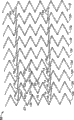
Fig. 8 is microphotograph, shows intracavity stent of the present invention part from about bundle jacket and discharges and radial dilatation.
Fig. 9 is microphotograph, shows intracavity stent of the present invention and is in the diameter state that it radially increases.
The specific embodiment
According to the invention provides some preferred embodiments.In each preferred embodiment of the present invention, the population structure of intracavity stent of the present invention is basic identical.Especially, specifically with reference to figure 1, intracavity stent 10 of the present invention generally comprises a tubular cylinder shape unit, this tubular cylinder shape unit comprise a plurality of usually around the circumferential axis C ' of support 10 form a plurality of closed hoops and relative to each other along the longitudinal axis L of support 10 ' coaxial adjacent circumferential expansion elements arranged spaced apart 12.A plurality of interconnecting members 14 interconnect adjoin all to a plurality of adjacent circumferential expansion elements 12.In a plurality of adjacent circumferential expansion elements 12 each all has the sinusoidal configuration substantially of a plurality of peak 12p and a plurality of paddy 12t, and a plurality of pillars 16 interconnect and adjoin peak 12p and paddy 12t.Be positioned at a plurality of peak 12p of a circumferential ring unit 12 and paddy 12t can with a plurality of peak 12p and the paddy 12t homophase or the out-phase of adjacent circumferential ring element 12.In addition, in each circumferential ring unit 12, peak 12p and paddy 12t can have rule or irregular cycle, the perhaps zone of zone of each had regular periods of a plurality of adjacent circumferential expansion elements and irregular cycle.In a plurality of interconnecting members 14 each preferably comprises each the linear unit that has width W i usually, interconnects the pillar 16 of first adjacent circumferential expansion elements 12 and the pillar 16 of second adjacent circumferential expansion elements of adjoining 12.Each of a plurality of interconnecting members has common rectangular cross-sectional shape.According to each preferred embodiment of the present invention, 16 on each in a plurality of interconnecting members 14 and pillar interconnect the mid point that approximately is positioned at pillar 16 whole length.Each of a plurality of pillars 16 has width Ws and is generally rectangular cross section.
In addition, can have a plurality of end flange unit 11 shown in broken lines to be provided for being fixed on fixing point on the support 10 with transplanting the cover (not shown).End flange unit 11 can be placed on far-end, near-end or the two ends of support 10, preferably for peak 12p or the paddy 12t from terminal adjacent circumferential expansion elements 12 forms common rectilinear projection at the near-end of support 10 or far-end or two ends.In a plurality of flange unit 11 each also can comprise rounded distal or proximal end region so that transplant the fixing of cover.
With reference to figure 2 and 6, for the ease of support 10 of the present invention is punctured into first less delivery diameter, find preferably to be provided with the hinge-unit 22 of common U-shape, the pillar that this hinge-unit adjoins along each adjacent circumferential expansion elements 12 connection at each peak 12p and paddy 12t place.According to preferred embodiment of the present invention, the width that it is desirable to the unit hinge of each common U-shape is Wh, and Wh is less than the width Ws of the pillar 16 of its connection.By making Wh, find to be compressed more, thereby support of the present invention 10 does not more use the occasion of U-shape hinge-unit 22 to be compressed more by the hinge-unit 22 interconnective angle α that form between the pillar 16 that adjoin of common U-shape less than Ws.
In addition, find it is desirable to, according to best mode of the present invention, the end relatively of each has strain- relief sections 18 and 20 in a plurality of interconnecting members 14.Strain- relief sections 18 and 20 comprises the end portion of interconnecting members 14, and its width is Wt, and Wt is less than the width W i of interconnecting members 14.According to one embodiment of the present of invention, strain- relief sections 18 and 20 each all have common C-shape structure, and in the pillar 16 that connects interconnecting members 14 and adjacent circumferential expansion 12, cross over a radius.Also can consider with the terminal strain- relief sections 18 and 20 of other geometry replaced C-shape, for example S-shape, V-shape, M-shape, W-shape, U-shape or only be the extension of I-shape along the coaxial projection of longitudinal axis of each interconnecting members 14.
Fig. 2-5 has described other preferred embodiment of support 10 of the present invention.Each preferred embodiment among Fig. 2-5 shown in each comprises identical adjacent circumferential expansion elements 12, each this unit all have a plurality of peak 12p and paddy 12t and form a plurality of the interconnective pillar 16 of peak 12p and paddy 12t place, form peak 12p and paddy 12t common U-shape unit 22 and adjoin that each is interconnection by a plurality of interconnecting members 14 to adjacent circumferential expansion elements 12.Like this, in each Fig. 2-5, represent same section with same numeral.Other preferred embodiment 30,40,50,60 of the present invention is described in Fig. 2,3,4,5 respectively, and the main distinction is that the position of a plurality of interconnecting members 14 is different with direction.Among Fig. 2-5, each all describes support 30,40,50,60 with plane graph.Those skilled in the art should clear and definite plane graph be for convenience of description, and described support is a tubulose, and line A-A and B-B form along the support longitudinal axes L ' cut-off rule to adopt plan view the geometry arrangement of support is described.
Among Fig. 2, support 30 comprises a plurality of adjacent circumferential expansion elements 12 and a plurality of interconnecting members 14.Each connection in a plurality of interconnecting members 14 is adjoined all to adjacent circumferential expansion elements 14.Each interconnecting members 14 forms and being connected of the pillar 16 of each adjacent circumferential expansion 12, and is crossing about the mid point along the length of each pillar 16 greatly with pillar 16.A plurality of interconnecting members 14 are along the longitudinal axes L of support 30 ' form all grouping 14a, 14b, 14c, 14d, 14e and 14f.Since interconnecting members 14 be positioned at peak 12p and paddy 12t and pillar 16 around the folding plane of angle α, find to it is desirable to interconnecting members 14 each all from being parallel to the longitudinal axis L of support 30 ' angle beta of straight line skew with reinforcement adjacent circumferential expansion elements 12 at support 30 from the foldability during than minor diameter than the major diameter boil down to.In support 30, each in all grouping 14a-14f in a plurality of interconnecting members 14 has identical offset angle and all interconnecting members 14 are parallel to each other.In order to hold deviation angle β, and at support from when compressing, make interconnecting members 14 folding than major diameter than minor diameter, the strain-relief sections 18 that is positioned at each interconnecting members 14 end is opposite with 20 directions.Therefore, when from the tubular structure of support 30 with when near-end viewpoint P sees this support, first strain-relief sections 18 has usually to dextrorotation or clockwise common C-shape structure, and second strain-relief sections 20 have usually to left-handed or anticlockwise also be the structure of C-shape usually.
According to the preferred embodiment of support 30, find it is desirable to peak 12p or paddy 12t and interconnecting members and adopt 2: 1 ratio.Like this, as described, in each of a plurality of adjacent circumferential expansion elements 12, all there are 6 peak 12p to be connected each adjacent circumferential expansion elements 12 to adjoining with 6 paddy 12t and 3 interconnecting members 14.Similarly, adjoin each to adjacent circumferential expansion elements 12 between, interconnecting members 14 departs from a peak 12p and a paddy 12t with the interconnecting members 14 of adjoining a pair of adjacent circumferential expansion elements 12 along circumference.Therefore, interconnecting members among group 14a, 14c and the 14e interconnects each to adjacent circumferential expansion elements 12a-12b, 12c-12d, 12e-12f, 12g-12h and 12i-12j, and the interconnecting members among group 14b, 14d and the 14f interconnects each to adjacent circumferential expansion elements 12b-12c, 12d-12f, 12f-12g, 12g-12h.Each all departs from a peak 12p and a paddy 12t along the circumference axle of each adjacent circumferential expansion elements 12 interconnecting members among group 14a, 14c and the 14e.
As shown in Figure 3, support 40 has adjacent circumferential expansion elements 12 and interconnecting members 14 structures much at one, but support 40 does not adopt 2: 1 ratios of peak 12p or paddy 12t and interconnecting members, but adopt 3: 1 ratio, like this adjacent circumferential expansion elements 12a-12i each 6 peak 12p and 6 paddy 12t are all arranged, but adjoin each adjacent circumferential expansion elements is only connected by two interconnecting members 14.The interconnecting members right as the right interconnecting members of support 30, the first adjacent circumferential expansion elements and the second adjacent adjacent circumferential expansion elements departs from along circumference, but departs from a peak 12p and two paddy 12t or two peak 12p and a paddy 12t in the support 40.There are four groups of interconnecting members 14a, 14b, 14c and 14d to interconnect a plurality of adjacent circumferential expansion elements 12 in the support 40.Interconnecting members group 14a and 14c interconnection each to adjacent circumferential expansion elements 12b-12c, 12d-12e, 12f-12g, 12h-12i, interconnecting members group 14b and 14d interconnection each to adjacent circumferential expansion elements 12a-12b, 12c-12d, 12e-12f, 12g-12h.
In the support 40, each interconnecting members 14 also from the longitudinal axis of support with the angled skew of an angle beta, but a plurality of interconnecting members 14 and not all parallel to each other.But, interconnecting members among interconnecting members among interconnecting members group 14a and the 14c parallel to each other and interconnecting members group 14b and the 14d is parallel to each other, and the interconnecting members among interconnecting members group 14a and the 14c from angle beta of the longitudinal axis of support skew-, with differentiation be expressed as angle β+β, form with group 14b and 14d in interconnecting members with respect to longitudinal axis L ' depart from.Sign angle beta+and β-be departs from much at one angle in order to represent that these angles are represented from longitudinal axis L ', but with respect to the circumferential axis of support 40 different directions is arranged.
Refer now to Fig. 4, described support 50 among Fig. 4.The same with 40 as above-mentioned support 30, support 50 has identical adjacent circumferential expansion elements 12, has a plurality of peak 12p and paddy 12t and the U-shape section 22 that interconnect a plurality of pillars 16, and interconnecting members 14.Yet a plurality of interconnecting members 14 form two groups of interconnecting members 14a and 14b in the support 50.Each independent interconnecting members 14 among interconnecting members 14a and the 14b is also from the longitudinal axes L of support 50 ' with one jiao of angled skew of β.And, each to adjacent circumferential expansion elements 12 in, interconnecting members group 14a and 14b depart from three peak 12p and three paddy 12t each other along circumference.Yet in each group interconnecting members 14a and 14b, each in a plurality of independent interconnecting members is arranged along common longitudinal axis basically.By this way, except the 12i circumferential ring unit of the 12a of nearside and farthest side, each in a plurality of interconnecting members greatly about the mid point of pillar 16 on each adjacent circumferential expansion elements 12b-12h, form one substantial 4 connect 19.These substantial 4 connect 19 and form between the distally of the nearside strain-relief sections 18 of the nearside of the distally of an interconnecting members strain-relief sections 20 and a pillar 16 and the interconnecting members 14 of adjoining and same pillar 16.
At last, as shown in Figure 5, show support 60.As support 30,40,50, support 60 comprises a plurality of adjacent circumferential expansion elements 12 and adjoins each interconnecting members 14 to adjacent circumferential expansion elements 12 with interconnecting.As the support among Fig. 3 40, the interconnecting members 14 of support 60 has many groups: 14a, 14b, 14c and 14d.Yet in support 60, it is all identical to adjacent circumferential expansion elements 12 that interconnecting members group 14a and 14d interconnect, and interconnecting members group 14b interconnects all identical to adjacent circumferential expansion elements 12 with 14c.Each interconnecting members among interconnecting members group 14a and the 14d from the longitudinal axis L ' of support 60 with an angle beta-become angular variation and parallel to each other.Similarly, each interconnecting members among interconnecting members group 14b and the 14c is from the longitudinal axis L of support 60 ' with an angle beta+become angular variation and parallel to each other.
For each adjacent circumferential expansion elements 12 for adjoining, interconnecting members 14 is from the longitudinal axes L of support 60 ' the different direction of skew.For example, for adjacent circumferential expansion elements for 12a-12b, the interconnecting members of 14b group and 14c group distinguish offset angle+and β-.Adjacent adjacent circumferential expansion elements to 12b one 12c in, the interconnecting unit of group 14a and 14d compile respectively move β-and β+.Therefore, adjoin each between the adjacent circumferential expansion elements 12, interconnecting members is an out-phase, and this is because they have the incline direction of different angle betas.In addition, adjoin each to adjacent circumferential expansion elements 12 between, interconnecting members departs from a peak 12p along circumference, and interconnecting members group 14a and interconnecting members group 14b depart from a peak 12p along circumference, and interconnecting members group 14c and interconnecting members group 14d depart from a peak 12p along circumference.And, independent each to adjacent circumferential expansion 12 in, each is to different along departing from of circumference between interconnecting members 14b-14c and the 14a-14d.Be 2 peak 12p and 3 paddy 12t along departing from of circumference between the interconnecting members group 14b-14c, and be 4 peak 12p and 3 paddy 12t along departing from of circumference between the interconnecting members group 14a-14d.
It will be understood by those skilled in the art that the aforementioned embodiment support 10,20,30,40 and 50 of having described different geometry arrangement all comprises common construction unit, promptly have each adjacent circumferential expansion elements 12 of a plurality of peak 12p and a plurality of paddy 12t and by hinge-unit 22 interconnective each pillar 16.Moreover, it will be understood by those skilled in the art that the present invention also considered to adjoin each between the adjacent circumferential expansion elements 12 along the number of the interconnecting members of the circumferential axis of support and the change of position, the specific embodiment that illustrates and describe with reference to accompanying drawing is exemplary in nature.
Yet Fig. 3 has represented the special preferred embodiment of support 40 of the present invention.The support 40 of invention is made with the inferior pipe of NiTi, goes out described geometry arrangement by cut.After the cut, support 40 is annealed so that the shape memory characteristic of support 40 to be set, and this support has the external diameter of the 5.8mm that increases when expanding fully and the length of 30.6mm.Support 40 can be contracted to another less contraction external diameter 1.4mm, and is placed on as shown in Figure 7 in the about bundle jacket.Because pillar 16 folds by angle [alpha] at hinge-unit 22 places of common U-shape and does not obviously hinder between adjacent circumferential expansion elements 12 and interconnecting members 14, thereby support 40 shows superior contractility.
Is that the 1.4mm radial dilatation is the process of 5.8mm to its second diameter that increases at support 40 than minor diameter from first of its compression, and support 40 does not represent the shortening characteristic that a lot of many support geometry arrangement known in the art are represented.Opposite with shortening, support 40 has unexpectedly extended 2.5%.The support that extends when up to now, this area does not still have radial dilatation.
Fig. 8 illustrates the situation when about bundle jacket support 40 radial dilatation when support 40 is removed.The state of the diameter when Fig. 9 has described support 40 and finally is in it and radially expands fully, only the portions of proximal of this support 40 is constrained on (not shown) in about beam guide tube.Fig. 6 is the part of an amplification of support 40, illustrate between adjacent circumferential expansion elements 12 and the interconnecting members 14, the distally is connected with the pillar-middle part of nearside strain-relief sections 18 with 20 places, the clear shape of U-substantially hinge-unit 22, peak 12p and the paddy 12t that has shown each adjacent circumferential expansion elements 12.Different between the width W t that Fig. 6 is also clear to show nearside and distally strain-relief sections and the width W i of the main body of interconnecting members 14, and different between the width Ws of the width W h of U-shape hinge-unit 22 and pillar 16.
A plurality of adjacent circumferential expansion elements 12 and interconnecting members 14 and their each component part are preferably made by the material of selecting the group of forming from titanium, vanadium, aluminum, nickel, tantalum, zirconium, chromium, silver, gold, silicon, magnesium, niobium, scandium, platinum, cobalt, palladium, manganese, molybdenum and their alloy, Nitinol and rustless steel.A plurality of adjacent circumferential expansion elements 12 and a plurality of interconnecting members 14 can be made and identical or different material behavior arranged by identical or different material.Term " material behavior " is intended to comprise physical characteristic, and physical characteristic is formed and grain boundary size, intragranular and intercrystalline precipitate including but not limited to flexible, hot strength, mechanical property, hardness, main body and/or surface microstructure size, crystal grain.Similarly, the material for a plurality of adjacent circumferential expansion elements 12 and 14 selections of a plurality of interconnecting members can be selected as having identical or different chemical characteristic.Term " chemical characteristic " is intended to comprise the change of any chemical reaction and material contingent state after implanting health and implants the physiological reaction of back health to material.
Though support of the present invention can be processed into by for example chemical etching of chemistry well known in the art, heat or mechanical ablative methods, cut, EDM or water spray, the preferred approach of the manufacturing support of also predicting of the present invention is for passing through the physical vapor deposition technology.The physical vapor deposition technology can strictly be controlled the tolerance of support geometry arrangement and the physics and the chemical characteristic of support and timbering material.Support 10,30,40,50 and 60 of the present invention, comprise its each unit and be each in adjacent circumferential expansion elements 12 and interconnecting members 14 and their the component part, preferably make by material integral body, that have controlled heterogeneity on its inner cavity surface.As the United States Patent (USP) the 6th of authorizing on April 30th, 2002,379, No. 383 division, unexamined, the U.S. Patent application the 09/754th of common transfer in December in 2000 submission on the 22nd, described in No. 304, this application is incorporated herein by reference, by being made, the integral material of support has definite crystallite dimension, chemistry and intragranular and the intercrystalline precipitate is controlled heterogeneity, and do not exist together generation along all zones or all positions of rack surface in whole and configuration of surface, keep acceptable or ideal protein binding ability simultaneously.The ideal characterisitics of rack characteristic of the present invention is: the ideal machine performance that (a) meets or surmount conventional Recognized Standards; (b) minimum such as the defective of crack or needle pore defect; (c) through 400MM circulation fatigue life that simulated acceleration test records; (d) anticorrosive and/or resistance to corrosion fatigue.(e) biocompatibility does not contain tangible biological impurities in the material; (f) almost the friction free outer surface with convenient no wound pass through and adapt by blood vessel and with the microcatheter technology of wearing that is used to introduce support; (g) have at the position of selecting the radiation impermeability and with the MRI compatibility; (h) have the best surface energy and the inner cavity surface of little looks; (i) manufacturing and the material cost of the minimum of coordinating mutually with the expectation material behavior that obtains; (j) yield rate height.
According to the present invention, identical with standardized material deposition methods by using in use and microelectronics and the little manufacturing vacuum coating technology, can obtain afore-mentioned characteristics in conjunction with material deposition methods manufacturing support for reference at this.Preferable deposition process comprises ion beam-assisted hydatogenesis and spraying technique.The preferable employing of ion beam-assisted hydatogenesis uses noble gas to basic unit's dual, synchronous thermionic electron beam evaporation of ionic bombardment simultaneously, and described noble gas is argon, xenon, nitrogen or neon for example.With noble gas for example argon ion bump can reduce pore volume by the atom packed density that in deposition process, increases institute's deposition materials.The minimizing of pore volume makes the material character of this deposition materials be similar to the character of integral material in the deposition materials.Utilize ion beam-assisted hydatogenesis technology can obtain sedimentation rate until 20 nm/sec.
When adopting spraying technique, can in about 4 hours sedimentation time, deposit the stainless steel membrane of 200 micron thickness.Spraying technique preferably adopts cylindric injection target and center ring is around the single circumferential injection source of substrate altogether, and this substrate is fixed in the injection source by coaxial.Other deposition process that can be used for forming according to support of the present invention have cathode arc, laser ablation and direct ion bundle deposition.When adopting vacuum deposition method, the crystal structure of deposited film influences the engineering properties of deposited film.These engineering propertiess of deposited film can be modified by post-process treatment such as for example annealing, HIGH PRESSURE TREATMENT or gas quenchings.
The material that is used to make support of the present invention according to its biocompatibility, engineering properties such as hot strength, yield strength and deposition easily degree select, comprise following: element titanium, vanadium, aluminum, nickel, tantalum, zirconium, chromium, silver, gold, silicon, magnesium, niobium, scandium, platinum, cobalt, palladium, manganese, molybdenum and their alloy, for example zirconium-titanium-tantalum alloy, Nitinol and rustless steel.
In the deposition process, the local pressure of cavity pressure, deposition pressure and processing gas is controlled, so that the deposition of material on substrate of expectation is optimized.Known as microelectronics manufacturing, little manufacturing and vacuum coating technical field, reactive and non-reactive gas is controlled and enters the inertia of deposit cavity or non-reactive gas material argon and nitrogen typically.Substrate can be fixed or active, or around self longitudinal axis rotation or movable in X-Y plane in reactor, to make things convenient for deposition or the formation pattern of deposition materials on substrate.Deposition materials can be deposited as the homogeneous solid film on substrate, also can form pattern in the following manner: (a) form positive or minus pattern by for example etching or photolithographic techniques on substrate, described etching or photolithographic techniques are applied to stromal surface to produce the positive or minus image of desired pattern.(b) use one or a cover fixed or determine to be applied to the pattern of substrate with respect to the active mould cover of substrate.Material thickness two aspects that the making of pattern is used in the dimensional orientation of pattern and deposited film zones of different obtain the finished product geometry arrangement of the complexity of finished product support, for example by on its length, changing the wall thickness of material, be used to thicken mount proximal end and far-end and open to prevent support end flue when the radial dilatation.
Behind any method formation support in the whole bag of tricks, this support can take off from substrate.For example, can by for example etching or dissolving of chemical method, by melt, machining or ultrasonic energy remove substrate.Perhaps, for example carbon or aluminum are as scapegoat's layer (sacrifice layer) can to deposit a kind of material between substrate and support, and scapegoat's layer can be by fusing, chemical method, melt, machining or other suitable method are removed so that support separates with substrate.
The finished product support can be accepted deposit post-treatment with the improvement crystal structure then, for example by annealing, or the improved surface feature, for example by the heterogeneity of etch effects with control support blood flow surface.
Can on the intracavity of support 10 and/or chamber outer surface, form a plurality of little paddy, as with more complete description among No. 99/23977, the international publication WO of the common transfer of the application, for reference at this in conjunction with this patent.A plurality of little paddy can be used as the deposit post-treatment step and form, for example by etching, or in deposition process, form, for example be deposited on the plug by support being formed material, this mandrel surface have cause metal as the part of deposition materials with the sedimentary little looks of little paddy pattern.
Each preferred embodiment of the present invention is preferable by adopting the vapor deposition techniques manufacturing, and this vapor deposition techniques makes support form the material gas deposition on substrate.Substrate can be planar or columned, can make in advance to have first and the pattern of one of the preferable geometry arrangement of interconnecting members, has positive or minus image, and perhaps substrate can be patternless.During the substrate pattern-free, sedimentary support forms material can deposit the back design producing, makes first and the pattern of one of all preferable geometry arrangement of interconnecting members sedimentary support is formed material.For all embodiments of the invention of making by vapor deposition techniques, do not need or only need minimum degree that the intracavity stent of making pattern is carried out deposit post-treatment, promptly modify the surface of support by processing machinery, electricity, heat or chemistry or finishing method.
The vapor deposition techniques manufacturing of intracavity stent of the present invention has lot of advantages, comprises the ability of the support of for example making the complex geometry arrangement, other very small dimensions tolerance of dust level, control fatigue life, corrosion resistance, corrosion fatigue, intragranular and intercrystalline precipitate and they are to the influence of corrosion resistance and corrosion fatigue, integral material is formed, the characteristic of main body and surfacing, the ability of radiation impermeability, and to influence the vertically flexible of support, hoop strength, the mode of radial dilatation performance and profile changes the profile of the unitary horizontal placement of supporting structure, the ability of Z-axial thickness and X-Y axle surface area.Integral material is formed can be adjusted to the element ratio of using in the alloy composition, and it is infeasible that the element ratio in this alloy composition is adjusted at when using tradition to form material.This adjustment makes the special alloy composition that obtains to have desirable material or engineering properties in the mode of optimizing alloy composition become possibility.For example, use the Ni-Ti pipe that the nickel that surpasses 51.5 atomic percents can be made the temporary shape memory and/or surpass flexible nature, because the high steady state stress (plateau stress) of this material performance, this can not finish when using traditional handicraft.Especially, adopt method of the present invention, the present invention has made the Ni-Ti alloy pipe of nickel content between 51.5 and 55 atomic percents.
According to a preferred embodiment of the present invention, the vapour deposition of intracavity stent of the present invention significantly reduces or has eliminated the inner and intercrystalline precipitate of crystal grain in the integral material in fact.In the Ni-Ti intracavitary unit is made, change by the precipitation state that the local grain Ni-Ti is recently controlled conversion temperature and final engineering properties is common.Be not required to be mechanical property in the present invention and control precipitation.When Ni-Ti in the present invention when the timbering material, local Ni-Ti than with integral material in Ni-Ti than being identical or identical in fact, but still can produce optimal morphology and need not precipitation heat and handle.Compare with the forged Ni-Ti alloy of tradition, the deposited stent of finished product forms the corrosion fatigue resistant characteristic that material shows superior corrosion resistance and therefore presents.
In vapor deposition process, a plurality of adjacent circumferential expansion elements 12 and a plurality of interconnecting members 14 can be made common rectangle, avette or oval cross section shape from structure, described shape of cross section has square edge or sloping edge or crooked inside and outside of cavity marginal surface leading and that trail on the longitudinal axis of support, so that the surface configuration of better blood flow to be provided.
Though described the present invention with reference to its preferred embodiment, it will be understood by those skilled in the art that and realize previous embodiment and have multiple version in vapour deposition and support manufacturing technology field, and the foregoing description only is descriptive, do not limit the scope of the invention, scope of the present invention is only limited by claims.
Claims (19)
1. intracavity stent comprises:
A. many adjacent circumferential expansion elements that coaxial line separates, described adjacent circumferential expansion elements forms piped substantially structure, and each described unit has the wave pattern substantially by interconnective peak of all pillars and paddy, wherein, described pillar forms rectilinear sections substantially, and interconnects by hinge-unit at the Feng Hegu place; With
B. many rectilinear substantially interconnecting members, described interconnecting members and all adjacent circumferential expansion elements being interconnected of adjoining, and be connected in and adjoin the about midpoint of pillar along the intracavity stent longitudinal axis,
Wherein, described a plurality of rectilinear substantially interconnecting members also comprise curved substantially first and second end sections, and described end sections is positioned at the relative terminal of each interconnecting members that connects with pillar.
2. intracavity stent as claimed in claim 1, it is characterized in that, each unit in described a plurality of adjacent circumferential expansion elements, along also comprising zigzag structure substantially on the circumferential axis of intracavity stent, whole width of the whole sections of wherein said pillar all are homogeneous substantially, and the width of described hinge-unit is narrower than the width of pillar, and wherein, peak and paddy and rectilinear substantially interconnecting members adopt at least 2: 1 ratio.
3. intracavity stent as claimed in claim 2 is characterized in that the width of curved first and second end sections is less than the width of described rectilinear interconnecting members substantially.
4. intracavity stent as claimed in claim 3 is characterized in that, each in each in a plurality of adjacent circumferential expansion elements and a plurality of interconnecting members be one with single.
5. intracavity stent as claimed in claim 4 is characterized in that, curved substantially first and second end sections of described a plurality of rectilinear interconnecting members substantially also comprise the sections that is C-shape substantially.
6. intracavity stent as claimed in claim 1 is characterized in that, described a plurality of rectilinear substantially interconnecting members are from being parallel to angle beta of straight line skew of described intracavity stent longitudinal axis.
7. intracavity stent as claimed in claim 1, it is characterized in that, described a plurality of rectilinear substantially interconnecting members is arranged as at least two group interconnecting members along the longitudinal axis of described intracavity stent, in the described at least two group interconnecting members first group with at least two group interconnecting members in second group of longitudinal axis with respect to intracavity stent have different incline directions.
8. intracavity stent as claimed in claim 1 is characterized in that, described intracavity stent is when from the longitudinal axis elongation along intracavity stent to than major diameter time of less expanded in diameter.
9. intracavity stent comprises:
A. many adjacent circumferential expansion elements that coaxial line separates, described adjacent circumferential expansion elements forms piped substantially structure, and each described unit has the wave pattern substantially by interconnective peak of all pillars and paddy, and along forming zigzag structure substantially on the circumferential axis of intracavity stent, wherein, described pillar forms rectilinear sections substantially, and interconnects by hinge-unit at the Feng Hegu place, and the width of described hinge-unit is narrower than the width of pillar; With
B. many rectilinear substantially interconnecting members, described interconnecting members comprises curved substantially first and second end sections, described end sections is positioned at the relative terminal of each interconnecting members that connects with pillar, curved substantially first and second end sections of each of described a plurality of rectilinear interconnecting members substantially also comprise the sections that is C-shape substantially, described a plurality of sections that is C-shape substantially has the width of the remainder width of the interconnecting members of being narrower than, described a plurality of rectilinear substantially interconnecting members with adjoin all to adjacent circumferential expansion elements to interconnecting, and be connected in and adjoin the about midpoint of pillar along the intracavity stent longitudinal axis; With
Wherein, each in each in a plurality of adjacent circumferential expansion elements and a plurality of interconnecting members be one with single.
10. intracavity stent comprises:
A. many adjacent circumferential expansion elements that coaxial line separates, described adjacent circumferential expansion elements forms piped substantially structure, and each described unit has the wave pattern substantially by interconnective peak of all pillars and paddy; With
B. many rectilinear substantially interconnecting members, described interconnecting members and all adjacent circumferential expansion elements being interconnected of adjoining, and be connected in by strain-relief sections and adjoin the about midpoint of pillar along the intracavity stent longitudinal axis, wherein, described strain-relief sections comprises the end sections of rectilinear interconnecting members, and its width is less than the width of rectilinear interconnecting members.
11. an intracavity stent comprises:
A. many adjacent circumferential expansion elements that coaxial line separates, described adjacent circumferential expansion elements forms piped structure, and each described unit has the wave pattern by interconnective peak of all pillars and paddy, wherein, described pillar forms rectilinear sections, and interconnects by hinge-unit at the Feng Hegu place;
B. many rectilinear interconnecting members, described interconnecting members and all adjacent circumferential expansion elements being interconnected of adjoining, and be connected in and adjoin the about midpoint of pillar along the intracavity stent longitudinal axis, described interconnecting members comprises curved first and second end sections, and each sections of described first and second end sections has the width that is narrower than described interconnecting members width.
12. intracavity stent as claimed in claim 11, it is characterized in that, each unit in described a plurality of adjacent circumferential expansion elements, along also comprising the zigzag structure on the circumferential axis of intracavity stent, whole width of the whole sections of wherein said pillar all are homogeneous.
13. intracavity stent as claimed in claim 11 is characterized in that, described curved first and second end sections are positioned at the relative terminal of each interconnecting members that connects with pillar.
14. intracavity stent as claimed in claim 13 is characterized in that, each in each in a plurality of adjacent circumferential expansion elements and a plurality of interconnecting members be one with single.
15. intracavity stent as claimed in claim 14 is characterized in that, curved first and second end sections of described a plurality of rectilinear interconnecting members also comprise the sections that is C-shape.
16. intracavity stent as claimed in claim 11 is characterized in that, described a plurality of rectilinear interconnecting members all are parallel to each other.
17. intracavity stent as claimed in claim 11, it is characterized in that, described a plurality of rectilinear interconnecting members is arranged as at least two group interconnecting members along the longitudinal axis of described intracavity stent, in the described at least two group interconnecting members first group with at least two group interconnecting members in second group of longitudinal axis with respect to intracavity stent have different incline directions.
18. intracavity stent as claimed in claim 11 is characterized in that, described intracavity stent is when from the longitudinal axis elongation along intracavity stent to than major diameter time of less expanded in diameter.
19. an intracavity stent comprises:
A. many adjacent circumferential expansion elements that coaxial line separates, described adjacent circumferential expansion elements forms piped structure, and each described unit has the wave pattern by interconnective peak of all pillars and paddy; With
B. many rectilinear interconnecting members, described interconnecting members and all adjacent circumferential expansion elements being interconnected of adjoining, and be connected in by strain-relief sections and adjoin the about midpoint of pillar along the intracavity stent longitudinal axis;
C. wherein, described strain-relief sections has the width that is narrower than described interconnecting members width.
Applications Claiming Priority (2)
| Application Number | Priority Date | Filing Date | Title |
|---|---|---|---|
| US45578303P | 2003-03-19 | 2003-03-19 | |
| US60/455,783 | 2003-03-19 |
Publications (2)
| Publication Number | Publication Date |
|---|---|
| CN1787793A CN1787793A (en) | 2006-06-14 |
| CN100558320C true CN100558320C (en) | 2009-11-11 |
Family
ID=34572701
Family Applications (1)
| Application Number | Title | Priority Date | Filing Date |
|---|---|---|---|
| CNB2004800129661A Expired - Lifetime CN100558320C (en) | 2003-03-19 | 2004-03-18 | Intracavity stent with intercolumniation interconnecting members |
Country Status (10)
| Country | Link |
|---|---|
| US (2) | US7122049B2 (en) |
| EP (2) | EP1610724B1 (en) |
| JP (1) | JP5021298B2 (en) |
| CN (1) | CN100558320C (en) |
| AT (1) | ATE492246T1 (en) |
| AU (1) | AU2004224415B2 (en) |
| CA (1) | CA2519226C (en) |
| DE (1) | DE602004030671D1 (en) |
| MX (1) | MXPA05009823A (en) |
| WO (1) | WO2004084764A2 (en) |
Families Citing this family (41)
| Publication number | Priority date | Publication date | Assignee | Title |
|---|---|---|---|---|
| US6261319B1 (en) | 1998-07-08 | 2001-07-17 | Scimed Life Systems, Inc. | Stent |
| US7736687B2 (en) | 2006-01-31 | 2010-06-15 | Advance Bio Prosthetic Surfaces, Ltd. | Methods of making medical devices |
| US6923829B2 (en) | 2002-11-25 | 2005-08-02 | Advanced Bio Prosthetic Surfaces, Ltd. | Implantable expandable medical devices having regions of differential mechanical properties and methods of making same |
| WO2006034050A2 (en) * | 2004-09-17 | 2006-03-30 | Cordis Neurovascular, Inc. | Thin film medical devices manufactured on application specific core shapes |
| US7344560B2 (en) * | 2004-10-08 | 2008-03-18 | Boston Scientific Scimed, Inc. | Medical devices and methods of making the same |
| US7837726B2 (en) * | 2005-03-14 | 2010-11-23 | Abbott Laboratories | Visible endoprosthesis |
| US20070213810A1 (en) * | 2005-03-14 | 2007-09-13 | Richard Newhauser | Segmented endoprosthesis |
| US20070255094A1 (en) * | 2005-03-14 | 2007-11-01 | Oepen Randolf V | Crack/fatigue resistant endoprosthesis |
| US20070088428A1 (en) * | 2005-09-15 | 2007-04-19 | Cappella, Inc. | Intraluminal device with asymmetric cap portion |
| US20070061003A1 (en) * | 2005-09-15 | 2007-03-15 | Cappella, Inc. | Segmented ostial protection device |
| US20100010622A1 (en) * | 2006-03-13 | 2010-01-14 | Abbott Laboratories | Hybrid segmented endoprosthesis |
| EP2020956A2 (en) | 2006-05-26 | 2009-02-11 | Nanyang Technological University | Implantable article, method of forming same and method for reducing thrombogenicity |
| AU2007299659B2 (en) * | 2006-09-21 | 2011-09-29 | Mico Innovations, Llc | A specially configured and surface modified medical device with certain design features that utilize the intrinsic properties of tungsten, zirconium, tantalum and/or niobium |
| US8974514B2 (en) | 2007-03-13 | 2015-03-10 | Abbott Cardiovascular Systems Inc. | Intravascular stent with integrated link and ring strut |
| ES2603282T3 (en) * | 2007-06-22 | 2017-02-24 | C.R. Bard, Inc. | Flexible stent with articulated connectors |
| JP2011512193A (en) * | 2008-02-15 | 2011-04-21 | フェモラリス リミテッド ライアビリティ カンパニー | Peripheral overlapping stent |
| EP2265299B1 (en) | 2008-04-08 | 2013-03-13 | Cook Medical Technologies LLC | Surface structure of a component of a medical device and a method of forming the surface structure |
| US8206636B2 (en) | 2008-06-20 | 2012-06-26 | Amaranth Medical Pte. | Stent fabrication via tubular casting processes |
| US10898620B2 (en) | 2008-06-20 | 2021-01-26 | Razmodics Llc | Composite stent having multi-axial flexibility and method of manufacture thereof |
| US8206635B2 (en) | 2008-06-20 | 2012-06-26 | Amaranth Medical Pte. | Stent fabrication via tubular casting processes |
| US9649211B2 (en) | 2009-11-04 | 2017-05-16 | Confluent Medical Technologies, Inc. | Alternating circumferential bridge stent design and methods for use thereof |
| EP2496189A4 (en) | 2009-11-04 | 2016-05-11 | Nitinol Devices And Components Inc | Alternating circumferential bridge stent design and methods for use thereof |
| CN102883684B (en) * | 2010-05-10 | 2015-04-08 | 爱德华兹生命科学公司 | Prosthetic heart valve |
| US9301864B2 (en) | 2010-06-08 | 2016-04-05 | Veniti, Inc. | Bi-directional stent delivery system |
| US8864811B2 (en) | 2010-06-08 | 2014-10-21 | Veniti, Inc. | Bi-directional stent delivery system |
| US9233014B2 (en) | 2010-09-24 | 2016-01-12 | Veniti, Inc. | Stent with support braces |
| CN102743245A (en) * | 2011-04-22 | 2012-10-24 | 陈启星 | Support opening type tubular vascular stent |
| US8728563B2 (en) | 2011-05-03 | 2014-05-20 | Palmaz Scientific, Inc. | Endoluminal implantable surfaces, stents, and grafts and method of making same |
| US20130035753A1 (en) * | 2011-08-01 | 2013-02-07 | Abbott Cardiovascular Systems Inc. | Multiple Scaffold Design And Coating Thereof |
| BR112014028242B1 (en) | 2012-05-14 | 2021-04-13 | C.R. Bard, Inc | INTRALUMINAL PROSTHESIS |
| US8834556B2 (en) * | 2012-08-13 | 2014-09-16 | Abbott Cardiovascular Systems Inc. | Segmented scaffold designs |
| US9517150B2 (en) * | 2012-10-23 | 2016-12-13 | Abbott Cardiovascular Systems Inc. | Time-dependent polymer scaffolds |
| USD723165S1 (en) | 2013-03-12 | 2015-02-24 | C. R. Bard, Inc. | Stent |
| CN105517509B (en) | 2013-03-13 | 2017-08-08 | 爱德华兹生命科学卡迪尔克有限责任公司 | Radial type joint valve bracket and method |
| US10271975B2 (en) * | 2013-03-15 | 2019-04-30 | Atrium Medical Corporation | Stent device having reduced foreshortening and recoil and method of making same |
| AU2014284216B2 (en) | 2013-06-21 | 2017-10-05 | Boston Scientific Scimed, Inc. | Stent with deflecting connector |
| US10722389B2 (en) | 2015-01-07 | 2020-07-28 | Sahajanand Medical Technologies Private Limited | Endoluminal stent |
| CN112043475B (en) * | 2015-10-27 | 2022-05-31 | 康特戈医疗股份有限公司 | Stent for use with an intraluminal angioplasty device |
| JP2019076121A (en) * | 2016-03-18 | 2019-05-23 | テルモ株式会社 | Stent |
| US10603165B2 (en) * | 2016-12-06 | 2020-03-31 | Edwards Lifesciences Corporation | Mechanically expanding heart valve and delivery apparatus therefor |
| CN109091275B (en) * | 2018-08-24 | 2024-01-30 | 四川大学 | Biodegradable stent |
Family Cites Families (72)
| Publication number | Priority date | Publication date | Assignee | Title |
|---|---|---|---|---|
| US4733665C2 (en) | 1985-11-07 | 2002-01-29 | Expandable Grafts Partnership | Expandable intraluminal graft and method and apparatus for implanting an expandable intraluminal graft |
| CA2079417C (en) | 1991-10-28 | 2003-01-07 | Lilip Lau | Expandable stents and method of making same |
| US6336938B1 (en) | 1992-08-06 | 2002-01-08 | William Cook Europe A/S | Implantable self expanding prosthetic device |
| JP2703510B2 (en) | 1993-12-28 | 1998-01-26 | アドヴァンスド カーディオヴァスキュラー システムズ インコーポレーテッド | Expandable stent and method of manufacturing the same |
| US5733303A (en) | 1994-03-17 | 1998-03-31 | Medinol Ltd. | Flexible expandable stent |
| US5843120A (en) | 1994-03-17 | 1998-12-01 | Medinol Ltd. | Flexible-expandable stent |
| US6165210A (en) | 1994-04-01 | 2000-12-26 | Gore Enterprise Holdings, Inc. | Self-expandable helical intravascular stent and stent-graft |
| US20020156523A1 (en) | 1994-08-31 | 2002-10-24 | Lilip Lau | Exterior supported self-expanding stent-graft |
| US6015429A (en) | 1994-09-08 | 2000-01-18 | Gore Enterprise Holdings, Inc. | Procedures for introducing stents and stent-grafts |
| AU3783195A (en) | 1994-11-15 | 1996-05-23 | Advanced Cardiovascular Systems Inc. | Intraluminal stent for attaching a graft |
| CA2163824C (en) | 1994-11-28 | 2000-06-20 | Richard J. Saunders | Method and apparatus for direct laser cutting of metal stents |
| US6896696B2 (en) | 1998-11-20 | 2005-05-24 | Scimed Life Systems, Inc. | Flexible and expandable stent |
| DE69637527D1 (en) | 1995-03-01 | 2008-06-26 | Boston Scient Scimed Inc | Longitudinally flexible and expandable stent |
| US6124523A (en) | 1995-03-10 | 2000-09-26 | Impra, Inc. | Encapsulated stent |
| US6059810A (en) | 1995-05-10 | 2000-05-09 | Scimed Life Systems, Inc. | Endovascular stent and method |
| US5776161A (en) * | 1995-10-16 | 1998-07-07 | Instent, Inc. | Medical stents, apparatus and method for making same |
| US5938682A (en) | 1996-01-26 | 1999-08-17 | Cordis Corporation | Axially flexible stent |
| US5772864A (en) | 1996-02-23 | 1998-06-30 | Meadox Medicals, Inc. | Method for manufacturing implantable medical devices |
| US6334871B1 (en) | 1996-03-13 | 2002-01-01 | Medtronic, Inc. | Radiopaque stent markers |
| FR2747301B1 (en) | 1996-04-10 | 1998-09-18 | Nycomed Lab Sa | IMPLANTABLE DEVICE FOR MAINTAINING OR RE-ESTABLISHING THE NORMAL PASSAGE SECTION OF A BODY DUCT, AS WELL AS A SYSTEM FOR ITS PLACEMENT |
| US5807404A (en) | 1996-09-19 | 1998-09-15 | Medinol Ltd. | Stent with variable features to optimize support and method of making such stent |
| US6325826B1 (en) | 1998-01-14 | 2001-12-04 | Advanced Stent Technologies, Inc. | Extendible stent apparatus |
| WO1998020810A1 (en) | 1996-11-12 | 1998-05-22 | Medtronic, Inc. | Flexible, radially expansible luminal prostheses |
| US5868782A (en) | 1996-12-24 | 1999-02-09 | Global Therapeutics, Inc. | Radially expandable axially non-contracting surgical stent |
| US5827321A (en) | 1997-02-07 | 1998-10-27 | Cornerstone Devices, Inc. | Non-Foreshortening intraluminal prosthesis |
| US5853419A (en) | 1997-03-17 | 1998-12-29 | Surface Genesis, Inc. | Stent |
| US5817126A (en) | 1997-03-17 | 1998-10-06 | Surface Genesis, Inc. | Compound stent |
| US6033433A (en) | 1997-04-25 | 2000-03-07 | Scimed Life Systems, Inc. | Stent configurations including spirals |
| US6451049B2 (en) | 1998-04-29 | 2002-09-17 | Sorin Biomedica Cardio, S.P.A. | Stents for angioplasty |
| IT1292295B1 (en) | 1997-04-29 | 1999-01-29 | Sorin Biomedica Cardio Spa | ANGIOPLASTIC STENT |
| US5741327A (en) | 1997-05-06 | 1998-04-21 | Global Therapeutics, Inc. | Surgical stent featuring radiopaque markers |
| US6070589A (en) * | 1997-08-01 | 2000-06-06 | Teramed, Inc. | Methods for deploying bypass graft stents |
| US6309414B1 (en) | 1997-11-04 | 2001-10-30 | Sorin Biomedica Cardio S.P.A. | Angioplasty stents |
| US6129755A (en) | 1998-01-09 | 2000-10-10 | Nitinol Development Corporation | Intravascular stent having an improved strut configuration |
| US6533807B2 (en) * | 1998-02-05 | 2003-03-18 | Medtronic, Inc. | Radially-expandable stent and delivery system |
| US6077296A (en) | 1998-03-04 | 2000-06-20 | Endologix, Inc. | Endoluminal vascular prosthesis |
| US6103320A (en) | 1998-03-05 | 2000-08-15 | Shincron Co., Ltd. | Method for forming a thin film of a metal compound by vacuum deposition |
| FR2777771B1 (en) | 1998-04-27 | 2000-08-25 | Microval | TUBULAR AND FLEXIBLE VASCULAR ENDOPROSTHESIS |
| US6066169A (en) * | 1998-06-02 | 2000-05-23 | Ave Connaught | Expandable stent having articulated connecting rods |
| US6203732B1 (en) * | 1998-07-02 | 2001-03-20 | Intra Therapeutics, Inc. | Method for manufacturing intraluminal device |
| DE19829702C1 (en) * | 1998-07-03 | 2000-03-16 | Heraeus Gmbh W C | Radially expandable support device V |
| US6261319B1 (en) * | 1998-07-08 | 2001-07-17 | Scimed Life Systems, Inc. | Stent |
| US6461380B1 (en) * | 1998-07-28 | 2002-10-08 | Advanced Cardiovascular Systems, Inc. | Stent configuration |
| US6042597A (en) | 1998-10-23 | 2000-03-28 | Scimed Life Systems, Inc. | Helical stent design |
| US6063101A (en) | 1998-11-20 | 2000-05-16 | Precision Vascular Systems, Inc. | Stent apparatus and method |
| US6120847A (en) | 1999-01-08 | 2000-09-19 | Scimed Life Systems, Inc. | Surface treatment method for stent coating |
| US6325825B1 (en) | 1999-04-08 | 2001-12-04 | Cordis Corporation | Stent with variable wall thickness |
| US6730116B1 (en) * | 1999-04-16 | 2004-05-04 | Medtronic, Inc. | Medical device for intraluminal endovascular stenting |
| US6273911B1 (en) | 1999-04-22 | 2001-08-14 | Advanced Cardiovascular Systems, Inc. | Variable strength stent |
| US6245101B1 (en) * | 1999-05-03 | 2001-06-12 | William J. Drasler | Intravascular hinge stent |
| US6375676B1 (en) | 1999-05-17 | 2002-04-23 | Advanced Cardiovascular Systems, Inc. | Self-expanding stent with enhanced delivery precision and stent delivery system |
| US6540774B1 (en) * | 1999-08-31 | 2003-04-01 | Advanced Cardiovascular Systems, Inc. | Stent design with end rings having enhanced strength and radiopacity |
| US20010047200A1 (en) | 1999-10-13 | 2001-11-29 | Raymond Sun | Non-foreshortening intraluminal prosthesis |
| US6387123B1 (en) | 1999-10-13 | 2002-05-14 | Advanced Cardiovascular Systems, Inc. | Stent with radiopaque core |
| US6537311B1 (en) | 1999-12-30 | 2003-03-25 | Advanced Cardiovascular Systems, Inc. | Stent designs for use in peripheral vessels |
| US6355058B1 (en) | 1999-12-30 | 2002-03-12 | Advanced Cardiovascular Systems, Inc. | Stent with radiopaque coating consisting of particles in a binder |
| US6312463B1 (en) | 2000-02-01 | 2001-11-06 | Endotex Interventional Systems, Inc. | Micro-porous mesh stent with hybrid structure |
| EP1132058A1 (en) | 2000-03-06 | 2001-09-12 | Advanced Laser Applications Holding S.A. | Intravascular prothesis |
| US20020072792A1 (en) | 2000-09-22 | 2002-06-13 | Robert Burgermeister | Stent with optimal strength and radiopacity characteristics |
| DE60136868D1 (en) | 2000-09-23 | 2009-01-15 | Boston Scient Scimed Inc | Intravascular stent |
| DE10050971A1 (en) | 2000-10-10 | 2002-04-11 | Biotronik Mess & Therapieg | stent |
| US6485508B1 (en) | 2000-10-13 | 2002-11-26 | Mcguinness Colm P. | Low profile stent |
| WO2002038080A2 (en) | 2000-11-07 | 2002-05-16 | Advanced Bio Prosthetic Surfaces, Ltd. | Endoluminal stent, self-fupporting endoluminal graft and methods of making same |
| US6506211B1 (en) | 2000-11-13 | 2003-01-14 | Scimed Life Systems, Inc. | Stent designs |
| EP1212986A1 (en) | 2000-12-08 | 2002-06-12 | SORIN BIOMEDICA CARDIO S.p.A. | An angioplasty stent and manufacturing method thereof |
| US7077859B2 (en) | 2000-12-22 | 2006-07-18 | Avantec Vascular Corporation | Apparatus and methods for variably controlled substance delivery from implanted prostheses |
| US6565599B1 (en) * | 2000-12-28 | 2003-05-20 | Advanced Cardiovascular Systems, Inc. | Hybrid stent |
| US6679911B2 (en) * | 2001-03-01 | 2004-01-20 | Cordis Corporation | Flexible stent |
| US6503272B2 (en) | 2001-03-21 | 2003-01-07 | Cordis Corporation | Stent-based venous valves |
| US6673106B2 (en) | 2001-06-14 | 2004-01-06 | Cordis Neurovascular, Inc. | Intravascular stent device |
| US6605110B2 (en) * | 2001-06-29 | 2003-08-12 | Advanced Cardiovascular Systems, Inc. | Stent with enhanced bendability and flexibility |
| US20040054399A1 (en) | 2002-09-17 | 2004-03-18 | Roth Noah M. | Anti-galvanic stent coating |
-
2004
- 2004-03-18 DE DE602004030671T patent/DE602004030671D1/en not_active Expired - Lifetime
- 2004-03-18 WO PCT/US2004/008247 patent/WO2004084764A2/en active Application Filing
- 2004-03-18 AT AT04757798T patent/ATE492246T1/en not_active IP Right Cessation
- 2004-03-18 CA CA2519226A patent/CA2519226C/en not_active Expired - Lifetime
- 2004-03-18 CN CNB2004800129661A patent/CN100558320C/en not_active Expired - Lifetime
- 2004-03-18 JP JP2006507303A patent/JP5021298B2/en not_active Expired - Lifetime
- 2004-03-18 EP EP04757798A patent/EP1610724B1/en not_active Expired - Lifetime
- 2004-03-18 EP EP10185232.5A patent/EP2289464B1/en not_active Expired - Lifetime
- 2004-03-18 AU AU2004224415A patent/AU2004224415B2/en not_active Expired
- 2004-03-18 US US10/803,392 patent/US7122049B2/en active Active
- 2004-03-18 MX MXPA05009823A patent/MXPA05009823A/en active IP Right Grant
-
2006
- 2006-10-13 US US11/549,493 patent/US7980289B2/en active Active
Also Published As
| Publication number | Publication date |
|---|---|
| ATE492246T1 (en) | 2011-01-15 |
| US20040186554A1 (en) | 2004-09-23 |
| US7980289B2 (en) | 2011-07-19 |
| AU2004224415B2 (en) | 2011-07-14 |
| EP2289464B1 (en) | 2018-08-01 |
| JP5021298B2 (en) | 2012-09-05 |
| WO2004084764A3 (en) | 2005-05-19 |
| US7122049B2 (en) | 2006-10-17 |
| CA2519226C (en) | 2013-01-15 |
| EP1610724B1 (en) | 2010-12-22 |
| CA2519226A1 (en) | 2004-10-07 |
| DE602004030671D1 (en) | 2011-02-03 |
| WO2004084764A2 (en) | 2004-10-07 |
| JP2006520648A (en) | 2006-09-14 |
| EP2289464A1 (en) | 2011-03-02 |
| CN1787793A (en) | 2006-06-14 |
| US20070088430A1 (en) | 2007-04-19 |
| AU2004224415A1 (en) | 2004-10-07 |
| EP1610724A4 (en) | 2007-06-13 |
| EP1610724A2 (en) | 2006-01-04 |
| MXPA05009823A (en) | 2006-03-13 |
Similar Documents
| Publication | Publication Date | Title |
|---|---|---|
| CN100558320C (en) | Intracavity stent with intercolumniation interconnecting members | |
| EP3001986B1 (en) | Balloon expandable bioabsorbable stent with a single stress concentration region interconnecting adjacent struts | |
| US10596018B2 (en) | Intravascular stent | |
| EP2063824B1 (en) | Helical implant having different ends | |
| US10433987B2 (en) | Highly flexible stent and method of manufacture | |
| US8882826B2 (en) | Intravascular stent | |
| US7273494B2 (en) | Stents for angioplasty | |
| US20030004567A1 (en) | Endoluminal stent, self-supporting endoluminal graft and methods of making same | |
| US20100241216A1 (en) | Stents for angioplasty | |
| EP4005537A1 (en) | Highly flexible stent and method of manufacture | |
| JP2003523792A (en) | Non-shortened endoluminal prosthesis | |
| JP2009526572A (en) | Highly flexible stent and manufacturing method | |
| WO2008100783A2 (en) | Highly flexible stent and method of manufacture | |
| JP4846414B2 (en) | In vivo indwelling stent and biological organ dilator | |
| JP5267457B2 (en) | Stent |
Legal Events
| Date | Code | Title | Description |
|---|---|---|---|
| C06 | Publication | ||
| PB01 | Publication | ||
| C10 | Entry into substantive examination | ||
| SE01 | Entry into force of request for substantive examination | ||
| C14 | Grant of patent or utility model | ||
| GR01 | Patent grant | ||
| CX01 | Expiry of patent term |
Granted publication date: 20091111 |