EP0003078A1 - Improvements in and relating to explosive cladding - Google Patents
Improvements in and relating to explosive cladding Download PDFInfo
- Publication number
- EP0003078A1 EP0003078A1 EP78300854A EP78300854A EP0003078A1 EP 0003078 A1 EP0003078 A1 EP 0003078A1 EP 78300854 A EP78300854 A EP 78300854A EP 78300854 A EP78300854 A EP 78300854A EP 0003078 A1 EP0003078 A1 EP 0003078A1
- Authority
- EP
- European Patent Office
- Prior art keywords
- plate
- flyer
- layer
- cladding
- explosive
- Prior art date
- Legal status (The legal status is an assumption and is not a legal conclusion. Google has not performed a legal analysis and makes no representation as to the accuracy of the status listed.)
- Withdrawn
Links
Images

Classifications
-
- B—PERFORMING OPERATIONS; TRANSPORTING
- B23—MACHINE TOOLS; METAL-WORKING NOT OTHERWISE PROVIDED FOR
- B23K—SOLDERING OR UNSOLDERING; WELDING; CLADDING OR PLATING BY SOLDERING OR WELDING; CUTTING BY APPLYING HEAT LOCALLY, e.g. FLAME CUTTING; WORKING BY LASER BEAM
- B23K20/00—Non-electric welding by applying impact or other pressure, with or without the application of heat, e.g. cladding or plating
- B23K20/06—Non-electric welding by applying impact or other pressure, with or without the application of heat, e.g. cladding or plating by means of high energy impulses, e.g. magnetic energy
- B23K20/08—Explosive welding
Definitions
- This invention relates to explosive cladding of structural metal members by a corrosion resistant metal layer and is particularly, although not exclusively, applicable to strip cladding across regions of fusion welded joints between two or more clad plates.
- the plate employed is usually steel, clad with a relatively thin layer of corrosion resistant metal such as, for example, titanium, and since it is not normally possible to fusion weld this layer to the base metal it is usually formed by explosive welding.
- the technique of forming this material is well known in the art.
- This method involves the use of a silver,titanium or copper insert which is laid within the gap and then bridged by an overlaid strip of titanium which is fusion welded to the titanium cladding along each side of the joint regicn.
- the insert acts as a filler material to prevent fatigue failure of the titanium strip and attendant welding.
- Similar techniques are employed for joining clad plate made in other such metallurgically incompatible combinations such as tantalum/steel and zirconium/steel.
- the object of this invention is to provide a less expensive,convenient method of surface cladding joints between clad metal plates which produces a high integrity weld.
- a method of applying a surface layer across a surface layer or joint between cladding layers on a clad metal plate or plates comprises forming a shallow chamfer along each opposing cladding layer edge and positioning over the said chamfers a corrosion resistant metal flyer-plate having a shallow generally V-shaped configuration, optionally applying a buffer layer of transmitting medium placed on the outside surface of the flyer-plate, further superimposing an explosive layer upon the flyer-plate or buffer layers and detonating the explosive layer so as to explosively weld the flyer-plate material at least to the cladding layers.
- a groove in the base metal layer of the clad plate centrally between the chamfered edges of the cladding layers, in order to facilitate positioning of the flyer-plate.
- the groove may conveniently be formed simultaneously with the chamfers of the cladding layers and effectively extends the chamfer surfaces.
- the invention is preferably applicable to the joint region of clad metal plates where two base metal plates have been fusion welded together.
- the flyer-plate may advantageously have integral extensions which become detached by the explosion, whereby high quality welds up to the flyer-plate edge are achieved.
- the extensions are conveniently defined by longitudinal grooves formed at the commencement of the extensions or by bending the extended flyer-plate along a line at the commencement of the extension in a direction outwardly from the base plate.
- each leg of the flyer-plate is provided with a pair of angled portions to provide for a partial weld to occur to the base or target as well as the cladding portions.
- the flyer-plate may be spaced apart from the base or target plate in order to modify the explosive weld between the flyer-plate and the base plate.
- a plastic explosive such as Metabel, (Registered Trade Mark) having a high detonation velocity is employed in the form of a flexible sheet.
- Metabel Registered Trade Mark
- the invention is applied to the fusion butt weld region joining two flat steel base plates 1 and lA.
- the cladding layers 2, 2A are machined back for a short distance from the weld region to prevent interference with the fusion welding process and shallow chamfers at an angle a are machined on the exposed ends of the cladding layers 2, 2A adjacent to the subsequently formed fusion weld zone 6.
- a rectangular flyer-plate 3 of cladding material compatible with the cladding layers 2, 2A is bent to a shallow generally 'V' configuration such that each side subtends an angle a and is closely positioned as shown.
- the sides may meet at an angle or on a radius along the apex.
- the angles a and ⁇ are determined on the basis of calculation of the required collision angle which provides the suitable set-up angle a-B required for explosive welding to take place.
- the flyer 3 will also be curved in side profile along the weld when the weld is curved or circumferential.
- the flyer-plate 3 is covered with a buffer layer 4 comprising a transmitting medium such as rubber and a layer of explosive medium 5 which is preferably a high detonation velocity explosive such as Metabel.
- the explosive medium 5 is detonated in the direction of the fusion weld seam, i.e. perpendicular to the section of the plate shown in Figure 1.
- the velocity of the flyer-plate 5 at impact is determined by the explosive loading and detonation velocity of layer 5; the collision angle and collision point velocity are determined by the velocity of the flyer-plate 3 and also by the angle ⁇ - ⁇ and may be calculated from a knowledge of the prior art.
- the extent of welding may be increased by forming an additional inclined portion 3B having an inclination of angle 8 to the target or base layers, 1, 1A so that inclined portion 3A form an angle a with the base 1, 1A and the portion 3B form a resultant angle ⁇ -S with the chamfers on the clad layers 2, 2A.
- the resultant weld after dressing is shown schematically in Figure 4 and it will be seen that welding of the flyer occurs right across the joint surface except for a narrow central region, due to the normal impact and the low stand-off.
- the edges of the cladding layers 2, and 2A and the portion of the base 1 and 1A adjacent to the weld 6 are machined at a chamfer angle a thereby forming a groove 7 above the weld 6, the angle a being the appropriately chosen welding angle.
- the flyer 3, with its sides including an angle 180°-2a is positioned with its apex in register in the groove 7.
- the flyer plate 3 advantageously has integral extensions 3C which can be coplanar with the flyer plate or bent upwards as shown.
- the flyer plate 3 has longitudinal grooves 8 at the commencement of the extensions.
- the buffer layer 4 and the explosive layer 5 covers all the area of flyer plate 3 and extensions 3C.
- the buffer layer 4 may also be locally thickened in the area immediately over the weld 6 for increased protection of the flyer plate in the region of the weld.
- the flyer or cladding plate 3 may be pre-formed with the buffer layer 4 and explosive charge layer 5 prior to welding and simple end jigs may be employed to maintain the required set-up geometry prior to detonation of the explosive layer.
- Welding may be performed on curved seams by using shaped (curved) flyers, provided that the correct relative angles are maintained.
- final closure of a full circumferential weld may not be achieved because of pressure doubling and overlap effects and therefore final closure of a small region only may require the more complex fusion welding technique to be employed.
- the method in accordance with the invention is applicable to seams lying in any direction or orientation, e.g. vertical, horizontal, overhead or downhand.
- Explosives whose detonation velocity fall within a wide range are suitable.
- plastic explosives such as Metabel which has a high detonation velocity, are preferred mainly on the grounds that they are readily moulded to shape and will stay in position without further packaging being required.
- an explosively welded seam can readily be inspected by ultrasonic techniques which are not applicable to fusion welded seams.
Abstract
A method of applying a surface layer across a surface layer or joint between cladding layers (2 and 2A) on a clad metal plate or plates comprises forming a shallow chamfer along each opposing cladding layer edge and positioning over the said chamfers a corrosion resistant metal flyer-plate (3) having a shallow generally V-shaped configuration, optionally applying a buffer layer (4) of transmitting medium placed on the outside surface of the flyer-plate, further superimposing an explosive layer (5) upon the cladding (3) and buffer (4) layers and detonating the explosive layer (5) so as to weld the flyer-plate material (3) at least to the cladding layers (2 and 2A). Advantageously a metal groove may be formed in the base metal layer of the clad plate to facilitate positioning of the flyer-plate, the groove wall conveniently being extensions of the cladding chamfer surfaces. The method facilitates an assembly of a cladding strip and explosive layer over a joint between clad metal plates in any orientation and gives joints of high quality between the cladding layers on the plates.
Description
- This invention relates to explosive cladding of structural metal members by a corrosion resistant metal layer and is particularly, although not exclusively, applicable to strip cladding across regions of fusion welded joints between two or more clad plates.
- There is an increasing use of corrosion resistant clad plate in the construction of vessels and structures for use in corrosive environments such as those experienced in chemical plant. The plate employed is usually steel, clad with a relatively thin layer of corrosion resistant metal such as, for example, titanium, and since it is not normally possible to fusion weld this layer to the base metal it is usually formed by explosive welding. The technique of forming this material is well known in the art.
- When large vessels are to be constructed it is often necessary to join two or more such clad plates together and this presents difficulties since it is not possible to fusion weld the complete clad plates. Thus to fabricate butt joints between titanium clad steel plates it is necessary to machine off the titanium cladding for a small distance so that fusion welding of the steel plates may then be effected without interference from the titanium cladding layer. It is then necessary to repair the gap in the titanium cladding to restore the corrosion resistant layer. One known method is described in a Paper entitled "Explosion Clads" by A H Holtzman - Proceedings of Seminar of NATO Advanced Study Institute on High Energy Rate Working of Metals - Oslo 1964, page 512. This method involves the use of a silver,titanium or copper insert which is laid within the gap and then bridged by an overlaid strip of titanium which is fusion welded to the titanium cladding along each side of the joint regicn. The insert acts as a filler material to prevent fatigue failure of the titanium strip and attendant welding. Similar techniques are employed for joining clad plate made in other such metallurgically incompatible combinations such as tantalum/steel and zirconium/steel.
- This solution is expensive due to the cost of the insert employed and the high degree of welding skill required to perform the joint.
- It has also been proposed in United Kingdom Patent Specification No. 986,435 to explosively weld a corrosion resistant layer across a fusion welded zone in clad metal plate by assembling over the fusion welded zone a strip of cladding metal and an overlying layer of explosive material and detonating the explosive along one edge. For best results the cladding strip was disposed at an angle to the clad metal base plate but the assembly is difficult to assemble accurately and the resultant weld is not uniform over the fusion welded zone.
- The object of this invention is to provide a less expensive,convenient method of surface cladding joints between clad metal plates which produces a high integrity weld.
- In accordance with the present invention a method of applying a surface layer across a surface layer or joint between cladding layers on a clad metal plate or plates comprises forming a shallow chamfer along each opposing cladding layer edge and positioning over the said chamfers a corrosion resistant metal flyer-plate having a shallow generally V-shaped configuration, optionally applying a buffer layer of transmitting medium placed on the outside surface of the flyer-plate, further superimposing an explosive layer upon the flyer-plate or buffer layers and detonating the explosive layer so as to explosively weld the flyer-plate material at least to the cladding layers.
- The optimum angles of the chamfers and the flyer-plate legs relative to the clad base plate for optimum welding may be calculated by known methods described, for example, in the following papers:-
- Papers by H K Wylie, P E G Williams and B Crossland entitled "An Experimental Investigation of Explosive Welding Parameters" - Proceedings of the first Symposium on the use of Explosive Energy in Manufacturing Metallic Materials of New Properties, Marianske Lazne, 1970, published by the Institute of Industrial Chemistry,Pardulice, Czechoslovakia and "Further Experimental Investigation of Explosive Welding Parameters" - Proceedings of the Third International Conference of the Center for High Energy Forming, Denver 1971.
- Paper by R H Wittman - Proceedings of the Second Symposium on Explosives Working of Metals at Marianske Lazne, 1973, Pages 153-167.
- Paper entitled "Some Aspects of Explosive Welding in Different Geometries" by M D Chadwick - Proceedings of The Welding Institute Select Conference on Explosive Welding, Hove 1968.
- In some cases it is advantageous to form a groove in the base metal layer of the clad plate centrally between the chamfered edges of the cladding layers, in order to facilitate positioning of the flyer-plate. The groove may conveniently be formed simultaneously with the chamfers of the cladding layers and effectively extends the chamfer surfaces.
- The invention is preferably applicable to the joint region of clad metal plates where two base metal plates have been fusion welded together.
- The flyer-plate may advantageously have integral extensions which become detached by the explosion, whereby high quality welds up to the flyer-plate edge are achieved. The extensions are conveniently defined by longitudinal grooves formed at the commencement of the extensions or by bending the extended flyer-plate along a line at the commencement of the extension in a direction outwardly from the base plate.
- In a further modification each leg of the flyer-plate is provided with a pair of angled portions to provide for a partial weld to occur to the base or target as well as the cladding portions.
- The flyer-plate may be spaced apart from the base or target plate in order to modify the explosive weld between the flyer-plate and the base plate.
- Preferably a plastic explosive, such as Metabel, (Registered Trade Mark) having a high detonation velocity is employed in the form of a flexible sheet.
- Other features of the invention will become apparent from the description which follows of three specific embodiments.
- The invention will now be described, by way of example only, with reference to the accompanying drawings in which
- Figure 1 shows a diagrammatic cross-section of one embodiment in accordance with the invention;
- Figure 2 shows schematically the resultant explosive weld achieved with the arrangement shown in Figure 1;
- Figure 3 shows a diagrammatic cross-section of an alternative embodiment in accordance with the invention.
- Figure 4 shows schematically the resultant explosive weld achieved with the arrangement shown in Figure 3.
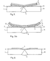
- Figure 5 shows a diagrammatic cross-section of a further embodiment in accordance with the invention.
- Figure 5A is a modification of the embodiment of Figure 5.
- Figure 6 shows schematically the resultant explosive weld achieved with the arrangement shown in Figures 5 and 5A.
- In the drawings like elements are designated by the same numeral.
- In the embodiments shown in Figures 1-6 the invention is applied to the fusion butt weld region joining two flat steel base plates 1 and lA. The
cladding layers cladding layers fusion weld zone 6. - As shown in Figure 1 a rectangular flyer-
plate 3 of cladding material compatible with thecladding layers flyer 3 will also be curved in side profile along the weld when the weld is curved or circumferential. - The flyer-
plate 3 is covered with a buffer layer 4 comprising a transmitting medium such as rubber and a layer ofexplosive medium 5 which is preferably a high detonation velocity explosive such as Metabel. - In order to avoid distortion of the
base plates 1 and 1A it may be necessary to place the base plates on a matching anvil such as a heavy metal plate which resists the detonation of the explosive. - The
explosive medium 5 is detonated in the direction of the fusion weld seam, i.e. perpendicular to the section of the plate shown in Figure 1. The velocity of the flyer-plate 5 at impact is determined by the explosive loading and detonation velocity oflayer 5; the collision angle and collision point velocity are determined by the velocity of the flyer-plate 3 and also by the angle α-β and may be calculated from a knowledge of the prior art. - The form of the resultant weld after dressing, i.e. removing excess material, is as shown in Figure 2. No weld occurs centrally, although in certain conditions some welding may take place between the
flyer 3 and thebase 1, 1A at some distance from the centre, but welding occurs along the sloping portions of the cladding, thereby effectively maintaining the continuity of the cladding across the joint region. - The arrangement described above with reference to Figures 1 and 2 is suitable when the weld zone width is small. However, when the weld zone is wider the embodiment illustrated in Figures 3 and 4 may be employed.
- Thus as shown in Figure 3 the extent of welding may be increased by forming an additional
inclined portion 3B having an inclination ofangle 8 to the target or base layers, 1, 1A so thatinclined portion 3A form an angle a with thebase 1, 1A and theportion 3B form a resultant angle γ-S with the chamfers on theclad layers - In the arrangement shown in Figure 5 the edges of the
cladding layers base 1 and 1A adjacent to theweld 6 are machined at a chamfer angle a thereby forming agroove 7 above theweld 6, the angle a being the appropriately chosen welding angle. Theflyer 3, with its sides including an angle 180°-2a is positioned with its apex in register in thegroove 7. - On detonation of the
explosive layer 5 the flyer is welded to the upper surface of thecladding layer - In the modified assembly of Figure 5A the
flyer plate 3 advantageously hasintegral extensions 3C which can be coplanar with the flyer plate or bent upwards as shown. In addition theflyer plate 3 haslongitudinal grooves 8 at the commencement of the extensions. - The buffer layer 4 and the
explosive layer 5 covers all the area offlyer plate 3 andextensions 3C. The buffer layer 4 may also be locally thickened in the area immediately over theweld 6 for increased protection of the flyer plate in the region of the weld. - On detonation of the
explosive layer 5 theextensions 3C become detached and the flyer is welded to the upper surface of thecladding layer - The invention described above has the following advantages:-The flyer or
cladding plate 3 may be pre-formed with the buffer layer 4 andexplosive charge layer 5 prior to welding and simple end jigs may be employed to maintain the required set-up geometry prior to detonation of the explosive layer. - Welding may be performed on curved seams by using shaped (curved) flyers, provided that the correct relative angles are maintained. However, final closure of a full circumferential weld may not be achieved because of pressure doubling and overlap effects and therefore final closure of a small region only may require the more complex fusion welding technique to be employed.
- The method in accordance with the invention is applicable to seams lying in any direction or orientation, e.g. vertical, horizontal, overhead or downhand.
- Explosives whose detonation velocity fall within a wide range are suitable. However, plastic explosives, such as Metabel which has a high detonation velocity, are preferred mainly on the grounds that they are readily moulded to shape and will stay in position without further packaging being required.
- It should also be noted that an explosively welded seam can readily be inspected by ultrasonic techniques which are not applicable to fusion welded seams.
Claims (13)
1. A method of applying a surface layer across a surface layer or joint between cladding layers on a clad metal plate or plates comprising forming a shallow chamfer along each opposing cladding layer edge and positioning over the said chamfers a corrosion resistant metal flyer-plate having a shallow generally V-shaped configuration, optionally applying a buffer layer of transmitting medium placed on the outside surface of the flyer plate, further superimposing an explosive layer upon the cladding-and buffer layers and detonating the explosive layer so as to weld the flyer-plate material at least to the cladding layers.
2. A method as claimed in Claim 1 characterised in that a groove is formed in the base metal layer of the clad plate centrally between the chamfer edges of the cladding layers, in which groove the flyer-plate is positioned.
3. A method as claimed in Claim 2 characterised in that the groove effectively extends the chamfer surfaces of the cladding layers.
4. A method as claimed in Claim 3 characterised in that the groove is formed simultaneously with the chamfers of the cladding layers.
5. A method as claimed in any one of Claims 1 to 4 inclusive characterised in that a surface layer is applied to a joint region of clad metal plates where two base metal plates have been fusion welded together.
6. A method as claimed in any one of Claims 1 to 5 inclusive characterised in that the flyer-plate has at least one integral extension which becomes detached by the explosion.
7. A method as claimed in Claim 6 characterised in that the extension is defined by a longitudinal groove formed at the commencement of the extension.
8. A method as claimed in Claim 6 characterised in that the extension is defined by bending the extended flyer-plate along a line at the commencement of the extension in a direction outwardly from the base plate.
9. A method as claimed in any one of Claims 1 to 8 inclusive characterised in that each leg of the flyer-plate is provided with a pair of angled portions to provide for a partial weld to occur to the base metal plate as well as to the cladding portions.
10. A method as claimed in any one of Claims 1 to 9 inclusive characterised in that the flyer-plate is spaced apart from the base metal plate. -
11. A method as claimed in any one of Claims 1 to 10 inclusive characterised in that the explosive layer comprises a plastic explosive.
12. A method as claimed in Claim 11 characterised in that the explosive is in the form of a flexible sheet.
13. A method as claimed in Claim 11 or Claim 12 characterised in that the explosive has a high detonation velocity.
Applications Claiming Priority (2)
| Application Number | Priority Date | Filing Date | Title |
|---|---|---|---|
| GB185078 | 1978-01-17 | ||
| GB185078 | 1978-01-17 |
Publications (1)
| Publication Number | Publication Date |
|---|---|
| EP0003078A1 true EP0003078A1 (en) | 1979-07-25 |
Family
ID=9729107
Family Applications (1)
| Application Number | Title | Priority Date | Filing Date |
|---|---|---|---|
| EP78300854A Withdrawn EP0003078A1 (en) | 1978-01-17 | 1978-12-18 | Improvements in and relating to explosive cladding |
Country Status (5)
| Country | Link |
|---|---|
| US (1) | US4272005A (en) |
| EP (1) | EP0003078A1 (en) |
| ES (1) | ES476937A1 (en) |
| IT (1) | IT1110700B (en) |
| ZA (1) | ZA7968B (en) |
Cited By (2)
| Publication number | Priority date | Publication date | Assignee | Title |
|---|---|---|---|---|
| US5050789A (en) * | 1990-10-02 | 1991-09-24 | The United States Of America As Represented By The United States National Aeronautics And Space Administration | Apparatus and method for explosive bonding to edge of flyer plate |
| WO1993019885A1 (en) * | 1992-04-02 | 1993-10-14 | Heinrich Hampel | Process for increasing the corrosion resistance of weld seams |
Families Citing this family (17)
| Publication number | Priority date | Publication date | Assignee | Title |
|---|---|---|---|---|
| US4552298A (en) * | 1983-04-29 | 1985-11-12 | The United States Of America As Represented By The Secretary Of The Navy | Apparatus for attaching an underwater explosive pad eye |
| US4708280A (en) * | 1985-10-23 | 1987-11-24 | The United States Of America As Represented By The Administrator, National Aeronautics & Space Administration | Tool and process for miniature explosive joining of tubes |
| US4688691A (en) * | 1986-01-22 | 1987-08-25 | Nooter Corporation | Process for attaching clad components and pressure vessel formed thereby |
| SE458908B (en) * | 1986-11-07 | 1989-05-22 | Exploweld Ab | PROCEDURE FOR EXPLOSION WELDING OF THIN METAL LAYERS |
| US5305946A (en) * | 1992-11-05 | 1994-04-26 | Nooter Corporation | Welding process for clad metals |
| CA2206035C (en) * | 1997-05-23 | 2006-05-16 | Alexander Szecket | High energy contoured hermetic seal |
| KR20050020419A (en) * | 2003-08-22 | 2005-03-04 | 주식회사 티에스엠텍 | The structure of seam and The method of welding line for chemistry fluid tank made of high quality |
| AU2005200826B1 (en) * | 2005-02-24 | 2005-07-07 | W.E. Smith Engineering Pty Ltd | Method of joining clad metals and vessel produced thereby |
| US7588664B2 (en) * | 2005-07-27 | 2009-09-15 | Chicago Bridge & Iron Company | Oil distillation vacuum column with thickened plate in the vapor horn section |
| CN101239418B (en) * | 2008-02-19 | 2011-07-06 | 江苏大学 | Flying plate driving type laser micro-welding method and device |
| FR2935625B1 (en) * | 2008-09-05 | 2011-09-09 | Snecma | METHOD FOR MANUFACTURING A CIRCULAR REVOLUTION THERMAMECHANICAL PART COMPRISING A STEEL-COATED OR SUPERALLIATION TITANIUM-BASED CARRIER SUBSTRATE, TITANIUM-FIRE RESISTANT TURBOMACHINE COMPRESSOR CASE |
| RU2463139C1 (en) * | 2011-04-13 | 2012-10-10 | Государственное образовательное учреждение высшего профессионального образования Волгоградский государственный технический университет (ВолгГТУ) | Method of producing titanium-steel composite material |
| CN103433627B (en) * | 2013-08-05 | 2015-04-22 | 江苏大学 | Simple flyer sticking and clamping special device and usage thereof |
| NL2011608C2 (en) * | 2013-10-14 | 2015-06-16 | Synex Tube B V | METHOD FOR ATTACHING AT LEAST EACH OTHER OF AT LEAST TWO METAL PARTS OF WORK. |
| US10279421B2 (en) | 2013-10-31 | 2019-05-07 | Halliburton Energy Services, Inc. | Wellbore servicing assemblies and methods of using the same |
| CN106181016A (en) * | 2016-07-29 | 2016-12-07 | 西安交通大学 | The electromagnetic pulse of bimetallic stratiform composite board soldering joint drives welding system and method |
| US11576358B2 (en) * | 2018-03-30 | 2023-02-14 | Globeride, Inc. | Spigot joint fishing rod |
Citations (7)
| Publication number | Priority date | Publication date | Assignee | Title |
|---|---|---|---|---|
| DE129180C (en) * | ||||
| GB953789A (en) * | 1962-03-01 | 1964-04-02 | Ici Ltd | Welding of laminar metallic elements |
| FR1414401A (en) * | 1964-11-17 | 1965-10-15 | Wmf Wuerttemberg Metallwaren | Method and device for locally plating metal parts using energy produced by an explosion |
| BE681082A (en) * | 1965-05-19 | 1966-10-31 | ||
| DE1232806B (en) * | 1962-10-24 | 1967-01-19 | Ici Ltd | Method for joining two layers of a clad metal which are clad on a base metal and are spaced apart next to each other |
| US3728780A (en) * | 1970-01-24 | 1973-04-24 | Inst Science And Technology | Explosive cladding on geometrically non-uniform metal material |
| FR2233129A1 (en) * | 1973-06-12 | 1975-01-10 | Holland Explosive Metal |
Family Cites Families (5)
| Publication number | Priority date | Publication date | Assignee | Title |
|---|---|---|---|---|
| US3258841A (en) * | 1963-01-23 | 1966-07-05 | Du Pont | Method for explosively bonding metal layers |
| DE1248434B (en) * | 1963-11-18 | 1967-08-24 | Wmf Wuerttemberg Metallwaren | Arrangement for preferably local plating of metallic workpieces with one another by shock waves generated by explosives |
| SE324096B (en) * | 1969-09-11 | 1970-05-19 | Asea Ab | |
| US3732612A (en) * | 1971-06-02 | 1973-05-15 | Martin Marietta Corp | Method for explosive bonding of metals |
| US3987952A (en) * | 1972-05-12 | 1976-10-26 | Exxon Research And Engineering Company | Apparatus for explosive welding of hollow cylinders such as pipe |
-
1978
- 1978-12-18 EP EP78300854A patent/EP0003078A1/en not_active Withdrawn
-
1979
- 1979-01-08 ZA ZA00790068A patent/ZA7968B/en unknown
- 1979-01-15 US US06/003,515 patent/US4272005A/en not_active Expired - Lifetime
- 1979-01-16 IT IT19333/79A patent/IT1110700B/en active
- 1979-01-17 ES ES476937A patent/ES476937A1/en not_active Expired
Patent Citations (7)
| Publication number | Priority date | Publication date | Assignee | Title |
|---|---|---|---|---|
| DE129180C (en) * | ||||
| GB953789A (en) * | 1962-03-01 | 1964-04-02 | Ici Ltd | Welding of laminar metallic elements |
| DE1232806B (en) * | 1962-10-24 | 1967-01-19 | Ici Ltd | Method for joining two layers of a clad metal which are clad on a base metal and are spaced apart next to each other |
| FR1414401A (en) * | 1964-11-17 | 1965-10-15 | Wmf Wuerttemberg Metallwaren | Method and device for locally plating metal parts using energy produced by an explosion |
| BE681082A (en) * | 1965-05-19 | 1966-10-31 | ||
| US3728780A (en) * | 1970-01-24 | 1973-04-24 | Inst Science And Technology | Explosive cladding on geometrically non-uniform metal material |
| FR2233129A1 (en) * | 1973-06-12 | 1975-01-10 | Holland Explosive Metal |
Cited By (2)
| Publication number | Priority date | Publication date | Assignee | Title |
|---|---|---|---|---|
| US5050789A (en) * | 1990-10-02 | 1991-09-24 | The United States Of America As Represented By The United States National Aeronautics And Space Administration | Apparatus and method for explosive bonding to edge of flyer plate |
| WO1993019885A1 (en) * | 1992-04-02 | 1993-10-14 | Heinrich Hampel | Process for increasing the corrosion resistance of weld seams |
Also Published As
| Publication number | Publication date |
|---|---|
| IT1110700B (en) | 1985-12-23 |
| US4272005A (en) | 1981-06-09 |
| IT7919333A0 (en) | 1979-01-16 |
| ES476937A1 (en) | 1979-07-16 |
| ZA7968B (en) | 1979-12-27 |
Similar Documents
| Publication | Publication Date | Title |
|---|---|---|
| US4272005A (en) | Explosive cladding | |
| US3024879A (en) | Method of closing or joining integrated metal core panels and the structure produced | |
| US20050210819A1 (en) | Compressive flange sinusoidal structural member | |
| US4496096A (en) | Method of joining metal elements by explosion welding | |
| GB986435A (en) | Joining clad metal parts | |
| CA1107466A (en) | Explosive cladding | |
| US4901905A (en) | Charging system in the explosion welding of planar or curved workpieces | |
| US3407280A (en) | Spot weld hem joints | |
| JPH09226886A (en) | Lining panel | |
| Jennings | Welding design | |
| JPS57124578A (en) | Joining method for steel sheet pile | |
| SU1196195A1 (en) | Method of arc butt welding of shells | |
| SU1348707A1 (en) | Welded specimen for mechanical tests | |
| JPS5732880A (en) | One side welding method for tank base metal | |
| RU1818188C (en) | Process of overlap joint of sheets of aluminium and steel | |
| SU1632694A1 (en) | Method of flash-butt welding | |
| SU1687401A1 (en) | A method of two-stage electron-beam welding | |
| SU946844A1 (en) | Arc fusion welding method | |
| JPS61134459A (en) | Connection of reinforcing bar | |
| SU1181830A1 (en) | Method of electric-arc welding of pig iron | |
| JPS589779A (en) | Butt welding method | |
| JPH0459486B2 (en) | ||
| JPS6257779A (en) | Method for welding inside reinforcing plate of box-structure body | |
| JPS63123577A (en) | Welding procedure | |
| SU1551498A1 (en) | Method of preventing end cracks in arc welding |
Legal Events
| Date | Code | Title | Description |
|---|---|---|---|
| PUAI | Public reference made under article 153(3) epc to a published international application that has entered the european phase |
Free format text: ORIGINAL CODE: 0009012 |
|
| AK | Designated contracting states |
Designated state(s): BE CH DE FR GB LU NL SE |
|
| STAA | Information on the status of an ep patent application or granted ep patent |
Free format text: STATUS: THE APPLICATION HAS BEEN WITHDRAWN |
|
| 18W | Application withdrawn | ||
| RIN1 | Information on inventor provided before grant (corrected) |
Inventor name: ANDERSON, DAVID KEAY CRICHTON Inventor name: CLELAND, DAVID BLACKHALL Inventor name: JACKSON, PETER WOODALL |