EP0009253A1 - Retro-reflecting sheet material and method of manufacture - Google Patents
Retro-reflecting sheet material and method of manufacture Download PDFInfo
- Publication number
- EP0009253A1 EP0009253A1 EP79103558A EP79103558A EP0009253A1 EP 0009253 A1 EP0009253 A1 EP 0009253A1 EP 79103558 A EP79103558 A EP 79103558A EP 79103558 A EP79103558 A EP 79103558A EP 0009253 A1 EP0009253 A1 EP 0009253A1
- Authority
- EP
- European Patent Office
- Prior art keywords
- substrate
- retro
- beads
- layer
- platen
- Prior art date
- Legal status (The legal status is an assumption and is not a legal conclusion. Google has not performed a legal analysis and makes no representation as to the accuracy of the status listed.)
- Granted
Links
Images


Classifications
-
- B—PERFORMING OPERATIONS; TRANSPORTING
- B29—WORKING OF PLASTICS; WORKING OF SUBSTANCES IN A PLASTIC STATE IN GENERAL
- B29D—PRODUCING PARTICULAR ARTICLES FROM PLASTICS OR FROM SUBSTANCES IN A PLASTIC STATE
- B29D11/00—Producing optical elements, e.g. lenses or prisms
- B29D11/00605—Production of reflex reflectors
- B29D11/00615—Production of reflex reflectors moulded by partially embedding reflective elements, e.g. glass beads, into the surface of a support, e.g. to make prefabricated road markings
-
- G—PHYSICS
- G02—OPTICS
- G02B—OPTICAL ELEMENTS, SYSTEMS OR APPARATUS
- G02B5/00—Optical elements other than lenses
- G02B5/12—Reflex reflectors
- G02B5/126—Reflex reflectors including curved refracting surface
- G02B5/128—Reflex reflectors including curved refracting surface transparent spheres being embedded in matrix
Definitions
- This invention relates to retro-reflective sheet material (also known as reflex reflectors) and to a method of preparing the same.
- Retro-reflective material is well known and widely used in the prior art, mainly in connection with road signs and automobile licence plates and the like.
- the material is capable of reflecting an incident beam of light back in the general direction of the light source.
- a car headlight illuminates a road sign bearing such material in otherwise dark surroundings, the sign reflects a greater amount of light towards the driver than surrounding objects and is therefore clearly visible.
- the retro-reflective materials fall into two general types.
- the first type consists of spherical glass beads adhered to the surface of a transparent organic coating applied over a reflective metal (or other) substrate but only partially imbedded in it so that a glass-air interface is presented to incoming light.
- This type of material does not function as a retro-reflector when the surface is wet with water.
- the second type of material consists of high refractive index (about 1.9 and greater) glass beads suspended within a relatively thick film of a transparent organic coating (plastic film.) applied over a reflective metal substrate. Such material retains its retro- reflective properties when wet.
- the most effective retro-reflectors of the second type can be formed by positioning the glass beads at just the right distance from conforming segments of concave spherical mirrors of corresponding size located behind the individual beads. This optimum distance will vary depending on the diameter of the beads, their refractive index, and the refractive index of the medium in which they are suspended.
- Various known retro-reflectors embody such a structure but have generally been produced in the form of flexible tapes or sheets which are adhered to the desired object, such as a road sign.
- the step of adhering the tape to the object can be time consuming and uneconomical, and the tape may peel from the object after a period of exposure to the elements.
- U.S. Patent No. 2,543,800 issued on March 6, 1951 and - assigned to Minnesota Mining and Manufacturing Company discloses a retro-reflector in which the beads are spaced a small distance from corresponding reflector surfaces formed by pressing the beads partially into a moldable cushio layer having a reflective surface coating containing metallic flake pigment particles, the beads being spaced from the cushion layer by a thin film which may contain a transparent pigment. After the pressing peration the plastic layers are cured.
- One disadvantage )f such retro-reflectors is that the reflector surfaces formed by the cushion layer are not as reflective as a polished metal surface and therefore light is lost at :hese surfaces.
- U .S. Patent 3,922,433 issued on November 25, 1975 and assigned to Aluminum Company of America relates to partially embedding the spherical glass beads into a netallic coating while it is in the molten condition.
- This invention is an attempt to form a retro-reflective surface directly on a substrate made of a hard material, such as a road sign, without first forming a flexible tape to be adhered thereto.
- An iron-base substrate is dipped into a molten bath of aluminum, zinc, tin, lead or alloys thereof and is sprayed with the glass beads by an air gun as the substrate is withdrawn from the bath and the coating is still molten.
- This method has the disadvantages that it is expensive and the beads are not spaced from the reflective surface as is required for the optimum retro-reflection.
- a product of high quality can be produced by indenting the substrate surface by applying pressure to the glass beads when a platen is located between the surface of the layer containing the glass beads and a roller or the like used for applying said pressure.
- a method of preparing a retro-reflective surface on a substrate comprising providing a layer of transparent material on said surface of the substrate,-- adhering a mono layer of glass beads of refractive index to said transparent material, applying pressure to said glass beads to cause the beads to indent the surface of the substate, and applying a further layer of transparent material over said glass beads, characterized in that said substrate, at least at the surface to be indented, is made of an indentable metal, and said pressure is applied to the beads via a platen overlying said beads.
- a retro-reflector comprising a substrate having a surface, transparent material overlying said surface of said substrate, a mono layer of glass beads of high refractive index adhered to said transparent material, and a further layer of transparent material overlying said layer of glass beads, said surface of said substrate having indentations conforming to the adjacent glass beads and the separation of the glass beads from the substrate surface by said layer of transparent material being suitable for retro-reflection, characterized in that said substrate, at least at said surface thereof, is made of an indentable metal.
- the effectiveness of the platen is quite unexpected because the damage to the glass beads and misalignment of the beads with the conforming convex mirrors encountered in original attempts to form retro-reflective surfaces on hard substrates was believed to be due to the load required to force each bead to indent the substrate material via the intervening polymer layer. If a platen is used, the beads must be subject to the same loading in order to cause proper indentation, so it was unreasonable to expect a platen to prevent damage to the beads.
- the platen may take the form of any resilient or deformable material having substantially no tendency to adhere to the glass beads during the indentation step.
- the material of the platen should be sufficiently soft to be indented either elastically or plastically by the glass beads during the indenting step, but of course should be capable of transmitting sufficient force to the beads to cause the necessary indentation of the substrate.
- the platen may be a plate or sheet of aluminum or other metal. It has also unexpectedly been found that the platen can be a thin foil or web of metal or paper or similar material. Such thin foils or webs are particularly advantageous because they can be withdrawn from a roll of the material and passed virtually continuously through a roll mill with the beaded substrate. This makes the manufacture of the retro-reflective substrate economical particularly as the foil or web-like platens are themselves inexpensive.
- indentable metal substrate is used throughout this specification to refer to those substrates which can be used in the method of the invention, i.e., those having a hardness below the practical maximum hardness limit in the particular operating conditions.
- Very hard metals can be provided with a retro- reflective surface if the hard metals are first coated or "clad” with a softer metal because only the hardness of the surface layer of the substrate is important in the indentation step.
- the term “indentable metal substrate” therefore includes such structures.
- transparent is used in a wide sense throughout this specification and is intended to include materials that are sometimes referred to as semi-transparent. The important point is that the various layers overlying the substrate, and even the glass beads themselves, must be capable of transmitting sufficient light for the structure to function effectively as a retro-reflector. Any layer or material (e.g. pigment or dye) capable of transmitting sufficient light to .achieve this function is considered to be “transparent” in the context of this invention.
- a metal substrate having a retro-reflective surface can be prepared without carrying out the disadvantageous steps of first forming an adhesive tape having the retro-reflective characteristics followed by adhering the tape to the substrate.
- the indentable metal substrate is preferably first coated with a transparent layer of an organic polymeric material and the layer is allowed to harden or is cured. A second layer of an organic material is then applied as an adhesive material. Small glass beads are applied to the adhesive surface to form a mono-layer, the beads being as densely packed on the surface as possible. The adhesive is allowed to harden or is cured.
- the transparent- organic polymeric material it is also possible to combine in one layer the functions of space coat and adhesive.
- the first layer is partially dried or cured to a degree at which the glass beads applied to the surface will adhere to form a monolayer but will not sink excessively into the polymeric material before it can be completely cured or dried. Thus the required separation between beads and substrate is preserved.
- the structure thus formed in either one of the alternative methods above is pressed in a mill so that the surface of the metal substrate is indented by the glass beads. Although the glass beads cause the metal substrate to form indentations, the beads themselves do not directly contact the substrate and remain spaced therefrom by the polymer layer. The pressure applied to the beads during the indentation step is thus transmitted to the substrate layer via the polymer layer and is sufficient to cause concave deformations to form in the substrate metal.
- a platen prevents damage to the retro-reflective structure but this may be because the platen acts as a cushion and, by spreading out the load, reduces the unit pressure on the glass bead surfaces. Alternately, or in addition, the platen may avoid the relative motion between the beads and the pressure roll, or the like, which exists when no platen is used. Whichever mechanism is effective, the requirement for a platen was quite unexpected and its effectiveness in preventing damage to the glass beads and polymer layers is remarkable.
- the glass beads are covered with one or more layers of a transparent organic polymeric material and the polymeric material is cured or allowed to harden.
- the extra layer or layers protect the glass beads and provides a flat outer surface. If there is no overlying layer, a structure of the first type mentioned earlier would be produced which would lose its retroreflective properties when wet with water.
- any one of the layers of organic polymeric material may contain a pigment or dye in order to impart a colour to the retro-reflective surface.
- the pigment or dye should preferably be light fast and not heat sensitive. Clear pigments give the best results, although any stable type of pigment or dye can be employed provided the resulting pigmented layer remains transparent in the sense defined earlier in this specification.
- the indentable metal substrates are usually metals suitable for preparing objects such as road signs and markers and automobile licence plates. Softer metals are preferred in order to reduce the pressures required in the indentation step.
- Aluminum is the preferred material, although zinc-coated iron-base material has also proved very effective.
- the preferred aluminum alloys are soft alloys such as AA1100, although harder alloys like Alcan SW-30 (an Al-l/2% Mn type alloy) and AA5454 (having a hardness of 85 BHN) can also be used.
- angles of incidence at which retro-reflectivity takes place may be reduced to some extent when harder substrates are employed because of reduced indentation of the metal, it may be desirable in those applications where a very hard aluminum substrate is required to employ a clad substrate, i.e., a hard aluminum alloy as a core material and a softer alloy as a cladding.
- the glass beads preferably have diameters in the range 50 to 80 microns and are of high refractive index e.g., 1.9 . and higher. Glass beads obtainable from Flex-O-Lite Division of General Steel Industries Limited, St. Louis, U.S.A. under the designation Type 910-18 are found to be ' useful. These beads have diameters of about 75 microns and a refractive index of 2.1.
- Type 831 refractive index 1.9
- Type 938 refractive index 2.28
- Fol Glass 1020 refractive index 2.24
- the size of the beads is also a factor in determining the thickness of the space coat. For example:
- thermosetting polymers are more likely to have the toughness to withstand the pressing operation than thermoplastic polymers.
- An example is a thermosetting acrylic coating sold under the trade mark DURACRON 100 by Canadian Pittsburgh Industries Ltd. The same material or a different material can be used to form the other transparent layers of the product.
- the first layer should be hard and not susceptible to crazing, cracking or excessive attenuation during the indentation step, whereas the layers overlying the beads applied after the indentation step (top coat) need not be as hard but preferably should be able to release their solvent without "popping", i.e., the polymeric material should preferably have a smooth surface when dry.
- the transparent adhesive layer is usually quite soft so that it flows upwardly around the beads to some extent during the indentation step thus leaving the tops of the beads less proud from the surface than before the application of pressure. Only a relatively thin top coat is then required to cover the tops of the beads and to form a smooth outer surface. The requirement for a thin top coat is preferred because thinner coats are less prone to "solvent popping" than thicker coats.
- an adhesive layer it should preferably be as thin as possible to reduce any tendency of the glass beads to form more than a single layer on the adhesive surface.
- the indentation step can be carried out in a press mill or a roller mill, but a roller mill is preferred because this lends itself more readily to continuous processes. Moreover, greater loads are required when the pressure is applied statically because the area of contact is much greater than in a rolling mill. The pressure required is dictated to a large extent by the hardness of the substrate material, and the minimum pressure capable of producing satisfactory indentation is preferable because higher pressures merely increase the possibility of fracture of the beads or polymer layer. In the case of a mill having 4 inch diameter rolls, the loading of the mill usually falls within the range of 1400 to 7 900 N/cm of substrate width.
- the platen may take the form of a sheet of metal, e.g., aluminum, or may be a web of paper or a metal foil such as aluminum foil. Any suitable type of paper or metal foil can be employed, although plastic coated papers should preferably be avoided because the plastic may tend to adhere to the glass particles or press rolls.
- plastic coated papers should preferably be avoided because the plastic may tend to adhere to the glass particles or press rolls.
- the process can readily be made continuous.
- known coil coating techniques can be employed and the platen can be supplied to the press rollers from a large roll or the like and can be rewound after passing through the press for disposal or re-use.
- the surface of the indentable metal substrate should preferably be bright before the application of the space coat so that the metal surface forms a good reflector.
- the indentation step results in the formation of bright new metal surfaces within the concave indentations.
- a light source 1 e.g., a photoflood lamp or a spot lamp, shines through a circular aperture having a diameter of 5 cm onto a 10 cm square sample 3 of retro-reflective material.
- the aperture serves to define the area illuminated and to block out stray light from behind the sample.
- the sample is mounted on the axle of a synchronous motor 4 which causes the sample to rotate at 1 rev/minute.
- Light reflected by the sample in the direction of the light source 1 is caused to fall on a photocell 5.
- the light source and photocell are mounted 6 metres away from the aperture 2, and the photocell is protected from extraneous light sources by a cardboard cylinder 6.
- the output of the cell is recorded on a suitable pen recorder 7.
- the sample To measure the intensity of retro-reflected light the sample is set rotating and the output of the photocell recorded. Zero retro-reflectivity is taken as the light intensity when the sample is perpendicular to the aperture.
- the back of the sample holder is a specular reflector which can be used to calibrate the chart speed of the recorder with sample angle. Since small changes in optical alignment affect the intensity measurement, a standard reflector sheet is measured for each set of samples.
- the samples were made by first applying (by drawdown) a base coat of DURACRON 100 (Trade Mark) on panels of un- pretreated mill finish Alcan SW-30 aluminum alloy sheet 0.56 mm thick, and curing it at 260°C for 2 minutes. A second very thin adhesive coating of DURACRON 100 (Trade Mark) was then applied, allowed to partially dry for about 30 seconds at 205°C., and then "beaded” by dropping on it a copious quantity of the Flex-O-Lite (Trade Mark) beads and shaking off those which did not adhere. This procedure produced a single densely populated layer of beads adhering to, and partially embedded in, the surface. The adhesive coat holding the beads was then cured for 2 minutes at 260°C.
- a panel of the same aluminum sheet of corresponding size was laid over the beaded surface as a platen and the assembly passed through a sheet rolling mill for a nominal reduction of about 2 percent at a load of about 5800 N/cm of sample width.
- the platen was then removed and one or , more top coats of DURACRON 100 (Trade Mark) were applied and cured for two minutes at 260°C., thus filling in the interstices between the partially imbedded beads and providing a transparent top coat over them.
- the top coat thickness is the dry film thickness that would have been applied with the drawdown bars used had there been no beads adhering to the surface.
- the aluminum substrate has been distorted into conformity with the beads without the base coat having been broken or significantly thinned. That is, the spacing has been maintained while enough conformity has been introduced to make the difference between high and low quality reflectors.
- retro-reflective layers were formed in a similar manner to Example 1 on the following substrate metals as noted in Table 2 below and were rolled with the platens and at the pressures also noted in the Table.
- This Example shows that the harder alloys required for road signs and the like can be made directly retro- reflective by the method of the present invention.
- Figs. 6 to 10 show the retro-reflective properties of these samples compared with those of a commercial grade prior art tape. In the case of some of the alloys, higher intensity of reflection than the prior art tape can be achieved with some sacrifice of reflection at the larger angles..
- samples were prepared from Alcan SW-30 aluminum alloy and AA5454 H-36 aluminum alloy starting with a. 12 . 7 cm x 3 0 .5 cm x 1.295 mm sheet of the alloy material.
- step (b) was kept as thin as possible to avoid any "second layer” beads adhering to the samples.
- the samples were each rolled in the 10 .2 cm mill with the platen arranged to cover only half the surface of each sample.
- Photomicrographs were made of both surface areas and also of the cross sections. In all cases, the area rolled without the platen showed fractured beads, while the panel area protected by the platen showed the beads intact.
- the samples were rolled using platens of different weight and quality of paper and foil to determine their effect on the retro-reflective properties.
- the alloy used for the samples was Alcan SW-30 (H-15 temper,0.584 mm thick).
- the thickness of the coating between the beads and the substrate was 8m.
- the beads had a refractive index of 2.28 and the rolling mill load applied was 4900 N/cm of sample width.
- a pretreated panel of Alcan SW-30 aluminum (size 10.2 cm x 25.4 cm x 0.559 mm) was coated with 8pm of. clear thermosetting acrylic lacquer and cured.
- a second coat of 8pm acrylic served as an adhesive for the glass beads having a refractive index of 2.28 (size 53 to 63pm) which were dusted on the adhesive layer to form a single, densely populated layer.
- the beaded panel was then cured.
- Aluminum foil (0.041 mm thick) of the same size as the panel was placed on top of the beaded surface and fed into a rolling mill loaded sufficiently to produce a 2% reduction in thickness at a load of about 5800 N/cm of sample width.
- the panel was removed and was coated with 25 ⁇ m. of clear acrylic lacquer.
- the retro-reflective properties of the beaded coated sheet thus produced (designated sample 526) are shown in Fig.19 and compared with two commercially available retro-reflective tapes.
Abstract
Description
- This invention relates to retro-reflective sheet material (also known as reflex reflectors) and to a method of preparing the same.
- Retro-reflective material is well known and widely used in the prior art, mainly in connection with road signs and automobile licence plates and the like. The material is capable of reflecting an incident beam of light back in the general direction of the light source. When, for example, a car headlight illuminates a road sign bearing such material in otherwise dark surroundings, the sign reflects a greater amount of light towards the driver than surrounding objects and is therefore clearly visible.
- Known retro-reflective materials fall into two general types. The first type consists of spherical glass beads adhered to the surface of a transparent organic coating applied over a reflective metal (or other) substrate but only partially imbedded in it so that a glass-air interface is presented to incoming light. This type of material does not function as a retro-reflector when the surface is wet with water.
- The second type of material consists of high refractive index (about 1.9 and greater) glass beads suspended within a relatively thick film of a transparent organic coating (plastic film.) applied over a reflective metal substrate. Such material retains its retro- reflective properties when wet.
- Theoretical considerations dictate that the most effective retro-reflectors of the second type can be formed by positioning the glass beads at just the right distance from conforming segments of concave spherical mirrors of corresponding size located behind the individual beads. This optimum distance will vary depending on the diameter of the beads, their refractive index, and the refractive index of the medium in which they are suspended.
- Various known retro-reflectors embody such a structure but have generally been produced in the form of flexible tapes or sheets which are adhered to the desired object, such as a road sign. The step of adhering the tape to the object can be time consuming and uneconomical, and the tape may peel from the object after a period of exposure to the elements.
- One example of known retro-reflectors is disclosed in U.S. Patent 2,407,680 issued on September 17, 1946 and assigned to Minnesota Mining and Manufacturing Company. This patent was one of the first to disclose the second type of structure referred to above employing high refractive index spheres, and it is to be noted that it suggests the use of a polished metal surface as the back reflector with the beads spaced an optimum distance therefrom. The patent also suggests the formation of concave mirrors in a reflective surface formed by a reflective binder layer for the beads.
- U.S. Patent No. 2,543,800 issued on March 6, 1951 and - assigned to Minnesota Mining and Manufacturing Company discloses a retro-reflector in which the beads are spaced a small distance from corresponding reflector surfaces formed by pressing the beads partially into a moldable cushio layer having a reflective surface coating containing metallic flake pigment particles, the beads being spaced from the cushion layer by a thin film which may contain a transparent pigment. After the pressing peration the plastic layers are cured. One disadvantage )f such retro-reflectors is that the reflector surfaces formed by the cushion layer are not as reflective as a polished metal surface and therefore light is lost at :hese surfaces.
- U.S. Patent 3,922,433 issued on November 25, 1975 and assigned to Aluminum Company of America relates to partially embedding the spherical glass beads into a netallic coating while it is in the molten condition. This invention is an attempt to form a retro-reflective surface directly on a substrate made of a hard material, such as a road sign, without first forming a flexible tape to be adhered thereto. An iron-base substrate is dipped into a molten bath of aluminum, zinc, tin, lead or alloys thereof and is sprayed with the glass beads by an air gun as the substrate is withdrawn from the bath and the coating is still molten. This method has the disadvantages that it is expensive and the beads are not spaced from the reflective surface as is required for the optimum retro-reflection.
- There is therefore a need for a method of producing a retro-reflective surface directly onto hard metal substrates, which method permits the beads to be spaced by the optimum distance from conforming concave reflective surfaces.
- The formation of a plastic layer containing the glass beads and the pressing of the beads into the metal substrate has been contemplated but, because of the relative hardness of the substrate surface, it has been found that the beads tend to shatter and the layer of plastic between the beads and the substrate surface tends to become attenuated or damaged when the plastic layer is rolled with sufficient force to cause the beads to indent the substrate surface. Moreover, the beads tend to become mis-aligned with the indentations in the surface so that a useless product is produced.
- It has now unexpectedly been found that a product of high quality can be produced by indenting the substrate surface by applying pressure to the glass beads when a platen is located between the surface of the layer containing the glass beads and a roller or the like used for applying said pressure.
- Thus, according to one aspect of the invention, there is provided a method of preparing a retro-reflective surface on a substrate, comprising providing a layer of transparent material on said surface of the substrate,-- adhering a mono layer of glass beads of refractive index to said transparent material, applying pressure to said glass beads to cause the beads to indent the surface of the substate, and applying a further layer of transparent material over said glass beads, characterized in that said substrate, at least at the surface to be indented, is made of an indentable metal, and said pressure is applied to the beads via a platen overlying said beads.
- According to another aspect of the invention there is provided a retro-reflector comprising a substrate having a surface, transparent material overlying said surface of said substrate, a mono layer of glass beads of high refractive index adhered to said transparent material, and a further layer of transparent material overlying said layer of glass beads, said surface of said substrate having indentations conforming to the adjacent glass beads and the separation of the glass beads from the substrate surface by said layer of transparent material being suitable for retro-reflection, characterized in that said substrate, at least at said surface thereof, is made of an indentable metal.
- When a platen is used in the indentation step, it is found that, despite the large pressure or force required to force the glass beads to indent the substrate surface, the glass beads remain largely undamaged and the layer between the beads and the substrate is not significantly damaged or compressed.
- The effectiveness of the platen is quite unexpected because the damage to the glass beads and misalignment of the beads with the conforming convex mirrors encountered in original attempts to form retro-reflective surfaces on hard substrates was believed to be due to the load required to force each bead to indent the substrate material via the intervening polymer layer. If a platen is used, the beads must be subject to the same loading in order to cause proper indentation, so it was unreasonable to expect a platen to prevent damage to the beads.
- The platen may take the form of any resilient or deformable material having substantially no tendency to adhere to the glass beads during the indentation step. The material of the platen should be sufficiently soft to be indented either elastically or plastically by the glass beads during the indenting step, but of course should be capable of transmitting sufficient force to the beads to cause the necessary indentation of the substrate.
- Thus the platen may be a plate or sheet of aluminum or other metal. It has also unexpectedly been found that the platen can be a thin foil or web of metal or paper or similar material. Such thin foils or webs are particularly advantageous because they can be withdrawn from a roll of the material and passed virtually continuously through a roll mill with the beaded substrate. This makes the manufacture of the retro-reflective substrate economical particularly as the foil or web-like platens are themselves inexpensive.
- Although the use of a platen eliminates damage to the glass breads during the indentation step in the case of most metal substrates, some substrates (especially ferrous metals) are so hard that the loading required to produce indentation cannot be transmitted by the beads without considerable damage, even when a platen is used. These substrates can easily be identified from hardness tables and from simple trial and error. It is not possible to provide a maximum hardness limit beyond which the method of the invention cannot be effectively operated, because the limit varies somewhat with the particular type of pressing equipment, glass beads, platens, operating speeds, etc. However, as stated, the useful metal substrates will be readily identifiable by persons skilled in this technology. The term "indentable metal substrate" is used throughout this specification to refer to those substrates which can be used in the method of the invention, i.e., those having a hardness below the practical maximum hardness limit in the particular operating conditions.
- Very hard metals can be provided with a retro- reflective surface if the hard metals are first coated or "clad" with a softer metal because only the hardness of the surface layer of the substrate is important in the indentation step. The term "indentable metal substrate" therefore includes such structures.
- It is also to be noted that the term "transparent" is used in a wide sense throughout this specification and is intended to include materials that are sometimes referred to as semi-transparent. The important point is that the various layers overlying the substrate, and even the glass beads themselves, must be capable of transmitting sufficient light for the structure to function effectively as a retro-reflector. Any layer or material (e.g. pigment or dye) capable of transmitting sufficient light to .achieve this function is considered to be "transparent" in the context of this invention.
- The invention is described in more detail below in which reference is made to the preferred embodiments of the innention and to the accompanying drawings, in which:-
- Figure 1 is a diagram showing the apparatus used to measure the retro-reflective properties of various samples according to the invention and control samples;
- Figure 2 is a graph showing the relative intensity of reflected light versus the angle of incidence for samples according to the invention and comparison samples;
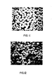
- Figure 3 is a cross-sectional photomicrograph of a non-rolled retro-reflective surface layer;
- Figure 4 is a cross-sectional photomicrograph of the retro-reflective surface layer of Figure 3 after rolling in accordance with the invention;
- Figure 5 is a cross-sectional photomicrograph of a prior art retro-reflective tape for comparison;
- Figures 6 to 10 are graphs similar to Figure 2 showing the reflective properties of samples prepared according to the present invention;
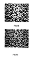
- Figure 11 is a photomicrograph of the surface of a retro-reflective layer on an Alcan SW-30 alloy rolled with a platen;
- Figure 12 is a photomicrograph of the same retro- reflective layer of Fig. 11 rolled without a platen;
- Figure 13 and Figure 14 are photomicrographs similar to Figs. 11 and 12, respectively, showing retro-reflective layers formed on AA5454 aluminum alloy;
- Figures 15 and 16 are cross-sectional photomicrographs of retro-reflective layers formed on AA5454 aluminum alloy rolled with and without a platen, respectively;
- Figures 17 and 18 are graphs similar to Figure 2 showing the reflective properties of various samples produced according to the invention using various types of foil as the platen; and
- Figure 19 is a graph similar to Fig. 2 showing the retro-reflective properties of the sample of Example 5 and two prior art tapes.
- In the preferred method of the present invention, a metal substrate having a retro-reflective surface can be prepared without carrying out the disadvantageous steps of first forming an adhesive tape having the retro-reflective characteristics followed by adhering the tape to the substrate.
- The indentable metal substrate is preferably first coated with a transparent layer of an organic polymeric material and the layer is allowed to harden or is cured. A second layer of an organic material is then applied as an adhesive material. Small glass beads are applied to the adhesive surface to form a mono-layer, the beads being as densely packed on the surface as possible. The adhesive is allowed to harden or is cured.
- Alternatively, by proper choice of the transparent- organic polymeric material it is also possible to combine in one layer the functions of space coat and adhesive. In this case the first layer is partially dried or cured to a degree at which the glass beads applied to the surface will adhere to form a monolayer but will not sink excessively into the polymeric material before it can be completely cured or dried. Thus the required separation between beads and substrate is preserved.
- The structure thus formed in either one of the alternative methods above is pressed in a mill so that the surface of the metal substrate is indented by the glass beads. Although the glass beads cause the metal substrate to form indentations, the beads themselves do not directly contact the substrate and remain spaced therefrom by the polymer layer. The pressure applied to the beads during the indentation step is thus transmitted to the substrate layer via the polymer layer and is sufficient to cause concave deformations to form in the substrate metal.
- By using a platen between the glass beads and the pressing roll or the like it has been found that suitable indentation of the surface can be obtained with little or no damage to the glass beads or to the transparent layer separating the beads from the surface of the substrate despite the considerable pressure required to obtain the indentation.
- It is not completely clear why the presence of a platen prevents damage to the retro-reflective structure but this may be because the platen acts as a cushion and, by spreading out the load, reduces the unit pressure on the glass bead surfaces. Alternately, or in addition, the platen may avoid the relative motion between the beads and the pressure roll, or the like, which exists when no platen is used. Whichever mechanism is effective, the requirement for a platen was quite unexpected and its effectiveness in preventing damage to the glass beads and polymer layers is remarkable.
- After the indentation step, the glass beads are covered with one or more layers of a transparent organic polymeric material and the polymeric material is cured or allowed to harden. The extra layer or layers protect the glass beads and provides a flat outer surface. If there is no overlying layer, a structure of the first type mentioned earlier would be produced which would lose its retroreflective properties when wet with water.
- Any one of the layers of organic polymeric material may contain a pigment or dye in order to impart a colour to the retro-reflective surface. The pigment or dye should preferably be light fast and not heat sensitive. Clear pigments give the best results, although any stable type of pigment or dye can be employed provided the resulting pigmented layer remains transparent in the sense defined earlier in this specification.
- The following general points should be considered when preparing retro-reflective substrates according to this invention:
- (i) The refractive index and size of the glass beads affects the optimum distance that the beads should be spaced from the substrate (i.e., smaller beads and higher refractive indices require smaller optimum spacings from the substrate);
- (ii) The rolling pressure applied to a given substrate metal affects the size of the angle of incidence for effective retro-reflection (the greater the pressure, the more the beads are indented into the substrate and the greater, is the angle of effective retro-reflection); and
- (iii) The layers of polymeric material applied over the glass beads after the indentation step should preferably be just sufficient to produce a flat surface because thicker layers reduce the intensity of the reflected light.
- The indentable metal substrates are usually metals suitable for preparing objects such as road signs and markers and automobile licence plates. Softer metals are preferred in order to reduce the pressures required in the indentation step. Aluminum is the preferred material, although zinc-coated iron-base material has also proved very effective. The preferred aluminum alloys are soft alloys such as AA1100, although harder alloys like Alcan SW-30 (an Al-l/2% Mn type alloy) and AA5454 (having a hardness of 85 BHN) can also be used. Since the angles of incidence at which retro-reflectivity takes place may be reduced to some extent when harder substrates are employed because of reduced indentation of the metal, it may be desirable in those applications where a very hard aluminum substrate is required to employ a clad substrate, i.e., a hard aluminum alloy as a core material and a softer alloy as a cladding.
- Although, as stated above, there is an upper limit on the hardness of the substrates beyond which the method of the invention may not be effective, there is no effective lower limit on the hardness of the substrates and very soft metals or metal foils can be employed if desired. The use of a pLaten is advantageous even in those cases in which the metal substrate may be soft enough to be indented at pressures unlikely to produce significant bead damage, because bead misalignment or displacement may still be caused if the substrates are indented without the use of a platen.
- The glass beads preferably have diameters in the
range 50 to 80 microns and are of high refractive index e.g., 1.9 . and higher. Glass beads obtainable from Flex-O-Lite Division of General Steel Industries Limited, St. Louis, U.S.A. under the designation Type 910-18 are found to be' useful. These beads have diameters of about 75 microns and a refractive index of 2.1. - Examples of other suitable glass beads are Type 831 (refractive index 1.9), Type 938 (refractive index 2.28) and Fol Glass 1020 (refractive index 2.24) all available from Flex-O-Lite, and UGB 2.32 Toshiba from Wanami Abrasive Company Ltd., Tokyo, Japan.
- As noted above, the lower the refractive index of the glass, the greater is the required thickness of the "space coat" (i.e., the first layer of organic polymeric material). The size of the beads is also a factor in determining the thickness of the space coat. For example:
- (i) beads of 1.9 refractive index and screen size 200/270 (50-80µm) require a space coat 22-25 µm in thickness;
- (ii) beads of 2.1 refractive index and screen size 200/270 require a space coat of 12-15 µm in thickness;
- (iii) beads of 2.24 and 2.28 refractive index and 230/270 screen size require a space coat of 10-12 µm in-thickness;
- (iv) beads of 2.32 refractive index and 230-325 screen size require a space coat 8-10 ,m in thickness.
- The required thickness of the space coat for each refractive index and bead size will be apparent to a person skilled in the art from the well-known theoretical considerations.
- Any suitable organic polymeric material having a strength when cured capable of resisting the pressures encountered during the indentation step without cracking or crazing can be used as the first layer of transparent material separating the glass beads from the metal substrate. In particular, it has been found that thermosetting polymers are more likely to have the toughness to withstand the pressing operation than thermoplastic polymers. An example is a thermosetting acrylic coating sold under the
trade mark DURACRON 100 by Canadian Pittsburgh Industries Ltd. The same material or a different material can be used to form the other transparent layers of the product. The important point is that the first layer (space coat) should be hard and not susceptible to crazing, cracking or excessive attenuation during the indentation step, whereas the layers overlying the beads applied after the indentation step (top coat) need not be as hard but preferably should be able to release their solvent without "popping", i.e., the polymeric material should preferably have a smooth surface when dry. - The transparent adhesive layer is usually quite soft so that it flows upwardly around the beads to some extent during the indentation step thus leaving the tops of the beads less proud from the surface than before the application of pressure. Only a relatively thin top coat is then required to cover the tops of the beads and to form a smooth outer surface. The requirement for a thin top coat is preferred because thinner coats are less prone to "solvent popping" than thicker coats.
- If an adhesive layer is employed, it should preferably be as thin as possible to reduce any tendency of the glass beads to form more than a single layer on the adhesive surface.
- Additional examples of suitable organic polymeric coating materials are listed as follows. While all of these materials are useful in the invention, some have minor disadvantages as discussed below.
- (i) Acryloid B-72 (Trade Mark) and Acryloid B-66 (Trade Mark) manufactured by Rohm & Haas. These thermoplastic materials are useful as top coats but do not meet the strength requirements of the first layer (space coat) subjected to the pressures of the indentation step.
- (ii) Automotive lacquers. These materials have very low flash points and require air drying, which has the disadvantage of being slower than oven drying.
- (iii) DuPont 1234 (Trade Mark). This material also has a very low flash point and requires air drying.
- (iv) Polyester and silicone polyester. These materials are particularly suitable as the space coat and can also be used for the top coats. A suitable solvent formulation can be provided to reduce their tendency to "solvent pop".
- (v) U.V. cured resins. These materials are suitable as top coats but tend to be expensive.
- (vi) Epoxy coatings. These materials are useful but generally have poor ultraviolet resistance when used outdoors.
- (vii) Water-borne acrylic emulsions such as the one sold by Rohm and Haas under the trade mark RHOPLEX E 1230. Such materials are particularly advantageous because their use does not cause environmental pollution.
- (viii) Fluorocarbon coatings based on polyvinyl fluoride or polyvinylidene fluoride resins are particularly suitable because of their characteristic good flexibility and durability.
- (ix) As top coats, preformed polymer films can be used, eliminating the need for special coating equipment and for drying and/or curing ovens with their associated air pollution problems. These films can be applied by standard laminating techniques employing adhesives coated on the film or the glass beads. They can also be thermally bonded to the beads in a "hot nip" or by melting, without the use of adhesives. Additionally, some thermoplastic materials used as top coats can be applied directly to the substrate in the molten state by standard extrusion coating techniques without the need to form a free film in a separate operation.
- The indentation step can be carried out in a press mill or a roller mill, but a roller mill is preferred because this lends itself more readily to continuous processes. Moreover, greater loads are required when the pressure is applied statically because the area of contact is much greater than in a rolling mill. The pressure required is dictated to a large extent by the hardness of the substrate material, and the minimum pressure capable of producing satisfactory indentation is preferable because higher pressures merely increase the possibility of fracture of the beads or polymer layer. In the case of a mill having 4 inch diameter rolls, the loading of the mill usually falls within the range of 1400 to 7900 N/cm of substrate width.
- As noted above, the platen may take the form of a sheet of metal, e.g., aluminum, or may be a web of paper or a metal foil such as aluminum foil. Any suitable type of paper or metal foil can be employed, although plastic coated papers should preferably be avoided because the plastic may tend to adhere to the glass particles or press rolls. When paper or a foil is used as the platen, the process can readily be made continuous. For example, known coil coating techniques can be employed and the platen can be supplied to the press rollers from a large roll or the like and can be rewound after passing through the press for disposal or re-use.
- The surface of the indentable metal substrate should preferably be bright before the application of the space coat so that the metal surface forms a good reflector. However, the indentation step results in the formation of bright new metal surfaces within the concave indentations.
- It has also been found advantageous for the production of a retroreflective coating with an improved white appearance to "white-etch" the substrate with the well known appropriate chemicals, as a pretreatment to coating.
- The invention will be described further with reference to the following Examples which are not intended to limit the scope of the invention.
- In these Examples, the retro-reflectance of samples was measured by using the apparatus shown in Fig. 1. A
light source 1, e.g., a photoflood lamp or a spot lamp, shines through a circular aperture having a diameter of 5 cm onto a 10 cmsquare sample 3 of retro-reflective material. The aperture serves to define the area illuminated and to block out stray light from behind the sample. - The sample is mounted on the axle of a
synchronous motor 4 which causes the sample to rotate at 1 rev/minute. Light reflected by the sample in the direction of thelight source 1 is caused to fall on aphotocell 5. The light source and photocell are mounted 6 metres away from the aperture 2, and the photocell is protected from extraneous light sources by a cardboard cylinder 6. The output of the cell is recorded on a suitable pen recorder 7. - To measure the intensity of retro-reflected light the sample is set rotating and the output of the photocell recorded. Zero retro-reflectivity is taken as the light intensity when the sample is perpendicular to the aperture. The back of the sample holder is a specular reflector which can be used to calibrate the chart speed of the recorder with sample angle. Since small changes in optical alignment affect the intensity measurement, a standard reflector sheet is measured for each set of samples.
- Two samples were prepared from clear,(unpigmented) DURACRON 100 (Trade Mark) thermosetting acrylic coating as the organic polymeric material and Flex-O-Lite (Trade Mark) spherical glass beads of about 75 microns in diameter and having a refractive index of 2.1.
- The samples were made by first applying (by drawdown) a base coat of DURACRON 100 (Trade Mark) on panels of un- pretreated mill finish Alcan SW-30 aluminum alloy sheet 0.56 mm thick, and curing it at 260°C for 2 minutes. A second very thin adhesive coating of DURACRON 100 (Trade Mark) was then applied, allowed to partially dry for about 30 seconds at 205°C., and then "beaded" by dropping on it a copious quantity of the Flex-O-Lite (Trade Mark) beads and shaking off those which did not adhere. This procedure produced a single densely populated layer of beads adhering to, and partially embedded in, the surface. The adhesive coat holding the beads was then cured for 2 minutes at 260°C.
- A panel of the same aluminum sheet of corresponding size was laid over the beaded surface as a platen and the assembly passed through a sheet rolling mill for a nominal reduction of about 2 percent at a load of about 5800 N/cm of sample width. The platen was then removed and one or , more top coats of DURACRON 100 (Trade Mark) were applied and cured for two minutes at 260°C., thus filling in the interstices between the partially imbedded beads and providing a transparent top coat over them.
- The approximate dimensions of the various layers in the two samples are given in Table 1 below:

- * The top coat thickness is the dry film thickness that would have been applied with the drawdown bars used had there been no beads adhering to the surface.
- For comparison, identical samples (designated 186 and 189 respectively) were prepared except that the rolling (indentation) step was omitted. The retro-reflective properties of the rolled and non-rolled constructions is shown in Figure 2.
- When the coating was removed from
samples 186/3 and 189/2 it was readily apparent that the aluminum substrate had been distorted into the form of a concave mirror behind each bead. In confirmation of this, constructions 186 (non-rolled) and 186/3 (rolled) were sectioned and photo- micrographed with the results shown in Figs. 3 and 4, respectively. For purposes of comparison, a similar photomicrograph of a prior art retro-reflecting adhesive tape is shown in Figure 5. - Of particular interest is that the aluminum substrate has been distorted into conformity with the beads without the base coat having been broken or significantly thinned. That is, the spacing has been maintained while enough conformity has been introduced to make the difference between high and low quality reflectors.
- In this Example, retro-reflective layers were formed in a similar manner to Example 1 on the following substrate metals as noted in Table 2 below and were rolled with the platens and at the pressures also noted in the Table.

- * All foil platens were 0.00406 mm thick aluminum foil.
- All samples formed acceptable retro-reflective layers with properties similar to the best prior art tapes. A 40% higher rolling pressure was required with the harder AA5052 and AA5454 aluminum alloys in order to indent the harder metal.
- This Example shows that the harder alloys required for road signs and the like can be made directly retro- reflective by the method of the present invention.
- Figs. 6 to 10 show the retro-reflective properties of these samples compared with those of a commercial grade prior art tape. In the case of some of the alloys, higher intensity of reflection than the prior art tape can be achieved with some sacrifice of reflection at the larger angles..
- In this Example, samples were prepared from Alcan SW-30 aluminum alloy and AA5454 H-36 aluminum alloy starting with a. 12.7 cm x 30.5 cm x 1.295 mm sheet of the alloy material.
- The following method steps were employed in the preparation of the samples:
- (a) A space coating of DURACRON 100 (Trade Mark, Canadian Pittsburgh Industries), a thermosetting acrylic polymer, was applied to the sample plate with a drawdown bar to a thickness of 8-10µm and the coating was cured for 120 seconds at 260°C.;
- (b) An adhesive coating of DURACRON 100 (Trade Mark) was applied over the cured layer to a thickness of 5-8pm and was cured for 30 seconds at 205°C.;
- (c) Glass beads (refractive index 2.32, diameter 40-50pm,obtained from Wanami Abrasive Company, Ltd., Tokyo, Japan) were sprinkled on the adhesive coating while it was still hot;
- (d) The bead coated sheet was cured for 90 seconds at 26C°C.;
- (e) Each sheet was trimmed to a width of 10.2 cm, and, using a 0.0406 mm thick aluminum foil as a platen, each sheet was passed once through a rolling mill having 10.2 cm diameter rolls, using a load of 6900 N/cm of sheet width, and the platen removed;
- (f) Each sheet then received two top coats of DURACRON 100 (Trade Mark) applied by a spray gun (producing a film which would have a thickness of 25 µm if applied to a flat sheet), the second coating being applied immediately after the first coat had been cured at 260°C. for two minutes.
- The adhesive coating of step (b) was kept as thin as possible to avoid any "second layer" beads adhering to the samples.
- To show the effectiveness of the use of a platen, the samples were each rolled in the 10.2 cm mill with the platen arranged to cover only half the surface of each sample.
- Photomicrographs were made of both surface areas and also of the cross sections. In all cases, the area rolled without the platen showed fractured beads, while the panel area protected by the platen showed the beads intact.
- The photomicrographs of the samples prepared in this manner are shown in Figs. 11 to 14, wherein
- Fig. 11 shows the surface of an Alcan SW-30 alloy sheet coated with beads and rolled with the protection of a platen;
- Fig. 12 shows the same Alcan SW-30 alloy sheet rolled without the protection of a platen;
- Fig. 13 shows the surface of an AA5454 alloy sheet coated with beads and rolled with the protection of a platen; and
- Fig. 14 shows the same alloy sheet rolled without the protection of a platen.
- All of the photomicrographs were taken at 160 times magnification.
- Cross-sectional photomicrographs also show the benefit of using a platen. These are shown in Figs. 15 and 16, in which:
- Fig. 15 shows the effect of rolling an AA5454 alloy sheet coated with beads with the protection of a platen;
- Fig. 16 shows the effect of rolling the same AA5454 alloy sheet without the protection of a platen.
- Both these photomicrographs were taken at 400 times magnification.
- These photomicrographs speak for themselves. It is clear from them that in all cases damage and dislocation of the glass beads results when rolling is effected without the protection a platen, but this can substantially be avoided when a platen is used.
- In this Example, samples were prepared in a similar manner to Example 3.
- The samples were rolled using platens of different weight and quality of paper and foil to determine their effect on the retro-reflective properties.
- The alloy used for the samples was Alcan SW-30 (H-15 temper,0.584 mm thick). The thickness of the coating between the beads and the substrate was 8m. The beads had a refractive index of 2.28 and the rolling mill load applied was 4900 N/cm of sample width.
- The reflective properties of the resulting samples are shown in Figs.17 and 18, in which the dotted lines represent a commerical prior art tape and the curve references indicate the foil platens shown below
- K1 Freezer paper (0.102 mm)
- K2 Kraft 10 lbs. (0.064 mm)
- K3 Wrapping paper (0.076 mm).
- T Tracing paper (100% rag, 0.064 mm thick)
- B Bond paper (100% rag, 0.127 mm thick)
- Fl Aluminum container foil (0.142 mm thick)
- F2 Aluminum converter foil (0.041 mm thick)
- It can be seen from the graphs that no significant difference can be attributed to the type or quality of platen. However, it is desirable to have stronger paper or foil when using higher pressures.
- A pretreated panel of Alcan SW-30 aluminum (size 10.2 cm x 25.4 cm x 0.559 mm) was coated with 8pm of. clear thermosetting acrylic lacquer and cured. A second coat of 8pm acrylic served as an adhesive for the glass beads having a refractive index of 2.28 (size 53 to 63pm) which were dusted on the adhesive layer to form a single, densely populated layer. The beaded panel was then cured.
- Aluminum foil (0.041 mm thick) of the same size as the panel was placed on top of the beaded surface and fed into a rolling mill loaded sufficiently to produce a 2% reduction in thickness at a load of about 5800 N/cm of sample width.
- The panel was removed and was coated with 25µm. of clear acrylic lacquer.
- The retro-reflective properties of the beaded coated sheet thus produced (designated sample 526) are shown in Fig.19 and compared with two commercially available retro-reflective tapes.
- As can be seen from the graph, the product of this Example compares favourably with the better of the two commercially available tapes.
Claims (30)
Priority Applications (1)
| Application Number | Priority Date | Filing Date | Title |
|---|---|---|---|
| CA311,780A CA1109308A (en) | 1979-09-20 | 1978-09-21 | Retro-reflecting sheet material |
Applications Claiming Priority (2)
| Application Number | Priority Date | Filing Date | Title |
|---|---|---|---|
| CA311,780A CA1109308A (en) | 1979-09-20 | 1978-09-21 | Retro-reflecting sheet material |
| CA311780 | 1978-09-21 |
Publications (2)
| Publication Number | Publication Date |
|---|---|
| EP0009253A1 true EP0009253A1 (en) | 1980-04-02 |
| EP0009253B1 EP0009253B1 (en) | 1984-03-21 |
Family
ID=4112408
Family Applications (1)
| Application Number | Title | Priority Date | Filing Date |
|---|---|---|---|
| EP79103558A Expired EP0009253B1 (en) | 1978-09-21 | 1979-09-20 | Retro-reflecting sheet material and method of manufacture |
Country Status (8)
| Country | Link |
|---|---|
| US (2) | US4265938A (en) |
| EP (1) | EP0009253B1 (en) |
| JP (1) | JPS5544899A (en) |
| AU (1) | AU525826B2 (en) |
| BR (1) | BR7906008A (en) |
| DE (1) | DE2966829D1 (en) |
| ES (2) | ES8101927A1 (en) |
| NO (1) | NO154779C (en) |
Cited By (2)
| Publication number | Priority date | Publication date | Assignee | Title |
|---|---|---|---|---|
| EP0224375A2 (en) * | 1985-11-22 | 1987-06-03 | Minnesota Mining And Manufacturing Company | Transparent non-vitreous zirconia microspheres |
| CN115798351A (en) * | 2022-12-19 | 2023-03-14 | 淮安惠铭光学材料有限公司 | Glass bead sealed capsule type vehicle body reflecting mark and processing technology thereof |
Families Citing this family (25)
| Publication number | Priority date | Publication date | Assignee | Title |
|---|---|---|---|---|
| US4756931A (en) * | 1984-11-30 | 1988-07-12 | Potters Industries, Inc. | Retroreflective materials and methods for their production and use |
| US4609587A (en) * | 1984-11-30 | 1986-09-02 | Potters Industries, Inc. | Retroreflective materials and use |
| US4814960A (en) * | 1986-05-14 | 1989-03-21 | Liu P Dong Guang | Glare control |
| US4907360A (en) * | 1987-07-30 | 1990-03-13 | Macmunn William G | Three-dimensional signage |
| US5073005A (en) * | 1988-05-02 | 1991-12-17 | Hubbs Machine & Manufacturing | Retro-reflective photogrammetric target |
| US5039200A (en) * | 1989-06-21 | 1991-08-13 | Linda Michler | Reflective safety stick for walking and jogging |
| US5410212A (en) * | 1993-04-01 | 1995-04-25 | General Electric Company | Soft white reflector lamp |
| NO301797B1 (en) * | 1995-12-22 | 1997-12-08 | Norsk Hydro As | Retroreflective plate material and method for making such material |
| US5736602A (en) * | 1996-04-09 | 1998-04-07 | Crocker; George L. | Retroreflective coating composition for coil coating application, method for application, and articles produced therefrom |
| US6265061B1 (en) | 1998-05-04 | 2001-07-24 | 3M Innovative Properties Company | Retroflective articles including a cured ceramer composite coating having abrasion and stain resistant characteristics |
| US6132861A (en) * | 1998-05-04 | 2000-10-17 | 3M Innovatives Properties Company | Retroreflective articles including a cured ceramer composite coating having a combination of excellent abrasion, dew and stain resistant characteristics |
| US6352758B1 (en) | 1998-05-04 | 2002-03-05 | 3M Innovative Properties Company | Patterned article having alternating hydrophilic and hydrophobic surface regions |
| US6245833B1 (en) | 1998-05-04 | 2001-06-12 | 3M Innovative Properties | Ceramer composition incorporating fluoro/silane component and having abrasion and stain resistant characteristics |
| WO2000034806A1 (en) * | 1998-12-09 | 2000-06-15 | Tomoegawa Paper Co., Ltd. | Filler lens and its manufacturing method |
| DK1144773T3 (en) | 1999-05-26 | 2007-01-15 | Basf Corp | Metal roof sheet starting material and process for making it |
| AU2001286537A1 (en) * | 2000-08-16 | 2002-02-25 | Randall Craft | Process for forming a reflective surface |
| KR100667679B1 (en) * | 2002-11-27 | 2007-01-12 | 기와 가가쿠 고교 가부시키가이샤 | Retroreflection sheet |
| FR2869041B1 (en) * | 2004-04-14 | 2006-12-22 | Sunis Sa Sa | RETRO REFLECTIVE COMPOSITIONS FOR SAFETY EQUIPMENT |
| FR2869040B1 (en) * | 2004-04-14 | 2006-05-26 | Sunis Sa Sa | RETRO-REFLECTIVE COMPOSITION |
| US7874686B2 (en) * | 2004-09-27 | 2011-01-25 | Brainlab Ag | Reflective marker and method for its manufacture |
| US7698826B2 (en) * | 2007-02-12 | 2010-04-20 | Hubbs Machine & Manufacturing Co. | Refurbishable retro-reflective photogrammetric target |
| US20100000977A1 (en) * | 2008-07-07 | 2010-01-07 | Ashok Sudhakar | Method for removal of content-based stripe and the like on a substrate and equipment thereof |
| DE102009019986B8 (en) | 2009-05-06 | 2013-08-01 | Ilumark Gmbh | Retro reflective marker |
| US9082062B2 (en) | 2011-10-10 | 2015-07-14 | Zortag, Inc. | Method of, and system and label for, authenticating objects in situ |
| US8915045B2 (en) | 2013-02-21 | 2014-12-23 | EML Products Inc. | Sleeves for sign posts |
Citations (9)
| Publication number | Priority date | Publication date | Assignee | Title |
|---|---|---|---|---|
| DE70C (en) * | 1877-08-07 | H. SCHMIDT, Ingenieur in Cüstrin | Steam boiler made of rings of U-shaped rolled iron and rivets removed by fire | |
| US3279316A (en) * | 1962-03-26 | 1966-10-18 | California Metal Enameling Com | Reflex reflecting article for use as a sign or the like |
| GB1081601A (en) * | 1963-08-07 | 1967-08-31 | Minnesota Mining & Mfg | Reflex reflecting sheets and articles |
| US3355311A (en) * | 1963-10-22 | 1967-11-28 | Pittsburgh Plate Glass Co | Reflective coatings |
| US3405025A (en) * | 1965-06-17 | 1968-10-08 | Canrad Prec Ind Inc | Retro-reflective assembly and method of making the same |
| US3413168A (en) * | 1967-05-03 | 1968-11-26 | Minnesota Mining & Mfg | Adhesive bonding method permitting precise positioning |
| US3473052A (en) * | 1968-05-08 | 1969-10-14 | Rca Corp | System for producing indications of time relationship of electrical signals |
| US3795435A (en) * | 1969-05-09 | 1974-03-05 | Swarovski & Co | Reflex light reflection sheet and method for its manufacture |
| US3994086A (en) * | 1974-01-09 | 1976-11-30 | Seibu Polymer Kasei Kabushiki Kaisha | Reflex light reflector |
Family Cites Families (4)
| Publication number | Priority date | Publication date | Assignee | Title |
|---|---|---|---|---|
| US2407680A (en) * | 1945-03-02 | 1946-09-17 | Minnesota Mining & Mfg | Reflex light reflector |
| US2543800A (en) * | 1947-12-05 | 1951-03-06 | Minnesota Mining & Mfg | Reflex light reflector |
| US3473952A (en) * | 1966-09-19 | 1969-10-21 | Minnesota Mining & Mfg | Fluorocarbon polymer release coating |
| US3922433A (en) * | 1971-03-01 | 1975-11-25 | Aluminum Co Of America | Aluminous metal with glass beads bonded to a metal substrate |
-
1979
- 1979-09-13 US US06/075,007 patent/US4265938A/en not_active Expired - Lifetime
- 1979-09-20 AU AU50987/79A patent/AU525826B2/en not_active Ceased
- 1979-09-20 EP EP79103558A patent/EP0009253B1/en not_active Expired
- 1979-09-20 ES ES484322A patent/ES8101927A1/en not_active Expired
- 1979-09-20 DE DE7979103558T patent/DE2966829D1/en not_active Expired
- 1979-09-20 BR BR7906008A patent/BR7906008A/en unknown
- 1979-09-20 NO NO793015A patent/NO154779C/en unknown
- 1979-09-21 JP JP12250579A patent/JPS5544899A/en active Granted
-
1980
- 1980-04-28 ES ES490980A patent/ES8103669A1/en not_active Expired
- 1980-10-27 US US06/201,156 patent/US4340273A/en not_active Expired - Lifetime
Patent Citations (9)
| Publication number | Priority date | Publication date | Assignee | Title |
|---|---|---|---|---|
| DE70C (en) * | 1877-08-07 | H. SCHMIDT, Ingenieur in Cüstrin | Steam boiler made of rings of U-shaped rolled iron and rivets removed by fire | |
| US3279316A (en) * | 1962-03-26 | 1966-10-18 | California Metal Enameling Com | Reflex reflecting article for use as a sign or the like |
| GB1081601A (en) * | 1963-08-07 | 1967-08-31 | Minnesota Mining & Mfg | Reflex reflecting sheets and articles |
| US3355311A (en) * | 1963-10-22 | 1967-11-28 | Pittsburgh Plate Glass Co | Reflective coatings |
| US3405025A (en) * | 1965-06-17 | 1968-10-08 | Canrad Prec Ind Inc | Retro-reflective assembly and method of making the same |
| US3413168A (en) * | 1967-05-03 | 1968-11-26 | Minnesota Mining & Mfg | Adhesive bonding method permitting precise positioning |
| US3473052A (en) * | 1968-05-08 | 1969-10-14 | Rca Corp | System for producing indications of time relationship of electrical signals |
| US3795435A (en) * | 1969-05-09 | 1974-03-05 | Swarovski & Co | Reflex light reflection sheet and method for its manufacture |
| US3994086A (en) * | 1974-01-09 | 1976-11-30 | Seibu Polymer Kasei Kabushiki Kaisha | Reflex light reflector |
Cited By (4)
| Publication number | Priority date | Publication date | Assignee | Title |
|---|---|---|---|---|
| EP0224375A2 (en) * | 1985-11-22 | 1987-06-03 | Minnesota Mining And Manufacturing Company | Transparent non-vitreous zirconia microspheres |
| EP0224375A3 (en) * | 1985-11-22 | 1988-09-21 | Minnesota Mining And Manufacturing Company | Transparent non-vitreous zirconia microspheres |
| CN115798351A (en) * | 2022-12-19 | 2023-03-14 | 淮安惠铭光学材料有限公司 | Glass bead sealed capsule type vehicle body reflecting mark and processing technology thereof |
| CN115798351B (en) * | 2022-12-19 | 2023-12-01 | 淮安惠铭光学材料有限公司 | Glass bead sealed capsule type vehicle body reflective marker and processing technology thereof |
Also Published As
| Publication number | Publication date |
|---|---|
| US4340273A (en) | 1982-07-20 |
| ES484322A0 (en) | 1980-12-16 |
| JPS5544899A (en) | 1980-03-29 |
| EP0009253B1 (en) | 1984-03-21 |
| BR7906008A (en) | 1980-09-09 |
| NO154779C (en) | 1987-01-02 |
| DE2966829D1 (en) | 1984-04-26 |
| NO154779B (en) | 1986-09-08 |
| AU525826B2 (en) | 1982-12-02 |
| JPS629023B2 (en) | 1987-02-26 |
| NO793015L (en) | 1980-03-24 |
| ES8101927A1 (en) | 1980-12-16 |
| ES490980A0 (en) | 1981-03-16 |
| US4265938A (en) | 1981-05-05 |
| AU5098779A (en) | 1980-03-27 |
| ES8103669A1 (en) | 1981-03-16 |
Similar Documents
| Publication | Publication Date | Title |
|---|---|---|
| EP0009253B1 (en) | Retro-reflecting sheet material and method of manufacture | |
| CA2574481C (en) | Retroreflective sheeting with security and/or decorative image | |
| KR950008008B1 (en) | Enclosed-lens retroreflective sheeting | |
| KR970003758B1 (en) | Retroreflective sheeting with backing film | |
| CA1307150C (en) | Retroreflective sheet material and method of making same | |
| EP0672920B1 (en) | Retroreflective sheet manufacturing method | |
| AU673270B2 (en) | Hot stamping foil | |
| JP2610253B2 (en) | Retroreflective sheet with wrapped flat surface and method of manufacturing the same | |
| US5962121A (en) | Retroreflective sheet comprising microspheres, the diameter and refractive index of which being specifically related to the refractive indices of layers directly in contact therewith | |
| KR20020053778A (en) | Removable reflective sheeting | |
| US5236751A (en) | Cone collars with temporary release coating and method for making and assembling same | |
| KR19990067297A (en) | Glass microspheres coated article having a smooth surface and manufacturing method thereof | |
| JPS62121047A (en) | Reverse reflective sheet with flat cover film | |
| EP0385746B1 (en) | High-brightness all-weather type pavement marking sheet material | |
| AU632587B2 (en) | Retroreflective security laminates with protective cover sheets | |
| EP0704719B1 (en) | Lens-type retroreflective sheeting | |
| RU2074095C1 (en) | Backward scattering sheet material (versions) | |
| US5756186A (en) | Layered reflector for light radiation, its manufacture and its use | |
| CA1109308A (en) | Retro-reflecting sheet material | |
| US6569510B1 (en) | Retro-flective sheeting on metal coil composites | |
| JPH1097208A (en) | Light retroreflection sheet | |
| MXPA99005268A (en) | Retroreflective sheet |
Legal Events
| Date | Code | Title | Description |
|---|---|---|---|
| PUAI | Public reference made under article 153(3) epc to a published international application that has entered the european phase |
Free format text: ORIGINAL CODE: 0009012 |
|
| AK | Designated contracting states |
Designated state(s): BE CH DE FR GB IT NL SE |
|
| 17P | Request for examination filed |
Effective date: 19800925 |
|
| ITF | It: translation for a ep patent filed |
Owner name: BARZANO' E ZANARDO MILANO S.P.A. |
|
| GRAA | (expected) grant |
Free format text: ORIGINAL CODE: 0009210 |
|
| AK | Designated contracting states |
Designated state(s): BE CH DE FR GB IT NL SE |
|
| REF | Corresponds to: |
Ref document number: 2966829 Country of ref document: DE Date of ref document: 19840426 |
|
| ET | Fr: translation filed | ||
| PLBE | No opposition filed within time limit |
Free format text: ORIGINAL CODE: 0009261 |
|
| PLBE | No opposition filed within time limit |
Free format text: ORIGINAL CODE: 0009261 |
|
| STAA | Information on the status of an ep patent application or granted ep patent |
Free format text: STATUS: NO OPPOSITION FILED WITHIN TIME LIMIT |
|
| 26N | No opposition filed | ||
| 26N | No opposition filed | ||
| ITTA | It: last paid annual fee | ||
| PGFP | Annual fee paid to national office [announced via postgrant information from national office to epo] |
Ref country code: FR Payment date: 19910813 Year of fee payment: 13 |
|
| PGFP | Annual fee paid to national office [announced via postgrant information from national office to epo] |
Ref country code: CH Payment date: 19910814 Year of fee payment: 13 |
|
| PGFP | Annual fee paid to national office [announced via postgrant information from national office to epo] |
Ref country code: SE Payment date: 19910816 Year of fee payment: 13 |
|
| PGFP | Annual fee paid to national office [announced via postgrant information from national office to epo] |
Ref country code: DE Payment date: 19910822 Year of fee payment: 13 Ref country code: BE Payment date: 19910822 Year of fee payment: 13 |
|
| PGFP | Annual fee paid to national office [announced via postgrant information from national office to epo] |
Ref country code: GB Payment date: 19910829 Year of fee payment: 13 |
|
| PGFP | Annual fee paid to national office [announced via postgrant information from national office to epo] |
Ref country code: NL Payment date: 19910930 Year of fee payment: 13 |
|
| PG25 | Lapsed in a contracting state [announced via postgrant information from national office to epo] |
Ref country code: GB Effective date: 19920920 |
|
| PG25 | Lapsed in a contracting state [announced via postgrant information from national office to epo] |
Ref country code: SE Effective date: 19920921 |
|
| PG25 | Lapsed in a contracting state [announced via postgrant information from national office to epo] |
Ref country code: CH Effective date: 19920930 Ref country code: BE Effective date: 19920930 |
|
| BERE | Be: lapsed |
Owner name: ALCAN RESEARCH AND DEVELOPMENT LTD Effective date: 19920930 |
|
| PG25 | Lapsed in a contracting state [announced via postgrant information from national office to epo] |
Ref country code: NL Effective date: 19930401 |
|
| NLV4 | Nl: lapsed or anulled due to non-payment of the annual fee | ||
| GBPC | Gb: european patent ceased through non-payment of renewal fee |
Effective date: 19920920 |
|
| PG25 | Lapsed in a contracting state [announced via postgrant information from national office to epo] |
Ref country code: FR Effective date: 19930528 |
|
| REG | Reference to a national code |
Ref country code: CH Ref legal event code: PL |
|
| PG25 | Lapsed in a contracting state [announced via postgrant information from national office to epo] |
Ref country code: DE Effective date: 19930602 |
|
| REG | Reference to a national code |
Ref country code: FR Ref legal event code: ST |
|
| EUG | Se: european patent has lapsed |
Ref document number: 79103558.7 Effective date: 19930406 |