EP0012319A1 - Verfahren und Schablone zum Befestigen von Bauelementen mit flächigen Anschlusskontakten auf Leiterplatten - Google Patents
Verfahren und Schablone zum Befestigen von Bauelementen mit flächigen Anschlusskontakten auf Leiterplatten Download PDFInfo
- Publication number
- EP0012319A1 EP0012319A1 EP79104855A EP79104855A EP0012319A1 EP 0012319 A1 EP0012319 A1 EP 0012319A1 EP 79104855 A EP79104855 A EP 79104855A EP 79104855 A EP79104855 A EP 79104855A EP 0012319 A1 EP0012319 A1 EP 0012319A1
- Authority
- EP
- European Patent Office
- Prior art keywords
- components
- circuit board
- template
- printed circuit
- flat
- Prior art date
- Legal status (The legal status is an assumption and is not a legal conclusion. Google has not performed a legal analysis and makes no representation as to the accuracy of the status listed.)
- Granted
Links
Images

Classifications
-
- B—PERFORMING OPERATIONS; TRANSPORTING
- B23—MACHINE TOOLS; METAL-WORKING NOT OTHERWISE PROVIDED FOR
- B23K—SOLDERING OR UNSOLDERING; WELDING; CLADDING OR PLATING BY SOLDERING OR WELDING; CUTTING BY APPLYING HEAT LOCALLY, e.g. FLAME CUTTING; WORKING BY LASER BEAM
- B23K3/00—Tools, devices, or special appurtenances for soldering, e.g. brazing, or unsoldering, not specially adapted for particular methods
- B23K3/08—Auxiliary devices therefor
- B23K3/087—Soldering or brazing jigs, fixtures or clamping means
-
- B—PERFORMING OPERATIONS; TRANSPORTING
- B23—MACHINE TOOLS; METAL-WORKING NOT OTHERWISE PROVIDED FOR
- B23K—SOLDERING OR UNSOLDERING; WELDING; CLADDING OR PLATING BY SOLDERING OR WELDING; CUTTING BY APPLYING HEAT LOCALLY, e.g. FLAME CUTTING; WORKING BY LASER BEAM
- B23K1/00—Soldering, e.g. brazing, or unsoldering
- B23K1/08—Soldering by means of dipping in molten solder
-
- H—ELECTRICITY
- H05—ELECTRIC TECHNIQUES NOT OTHERWISE PROVIDED FOR
- H05K—PRINTED CIRCUITS; CASINGS OR CONSTRUCTIONAL DETAILS OF ELECTRIC APPARATUS; MANUFACTURE OF ASSEMBLAGES OF ELECTRICAL COMPONENTS
- H05K3/00—Apparatus or processes for manufacturing printed circuits
- H05K3/30—Assembling printed circuits with electric components, e.g. with resistor
- H05K3/32—Assembling printed circuits with electric components, e.g. with resistor electrically connecting electric components or wires to printed circuits
- H05K3/34—Assembling printed circuits with electric components, e.g. with resistor electrically connecting electric components or wires to printed circuits by soldering
- H05K3/341—Surface mounted components
- H05K3/3431—Leadless components
- H05K3/3442—Leadless components having edge contacts, e.g. leadless chip capacitors, chip carriers
-
- H—ELECTRICITY
- H05—ELECTRIC TECHNIQUES NOT OTHERWISE PROVIDED FOR
- H05K—PRINTED CIRCUITS; CASINGS OR CONSTRUCTIONAL DETAILS OF ELECTRIC APPARATUS; MANUFACTURE OF ASSEMBLAGES OF ELECTRICAL COMPONENTS
- H05K3/00—Apparatus or processes for manufacturing printed circuits
- H05K3/30—Assembling printed circuits with electric components, e.g. with resistor
- H05K3/32—Assembling printed circuits with electric components, e.g. with resistor electrically connecting electric components or wires to printed circuits
- H05K3/34—Assembling printed circuits with electric components, e.g. with resistor electrically connecting electric components or wires to printed circuits by soldering
- H05K3/3457—Solder materials or compositions; Methods of application thereof
- H05K3/3468—Applying molten solder
-
- B—PERFORMING OPERATIONS; TRANSPORTING
- B23—MACHINE TOOLS; METAL-WORKING NOT OTHERWISE PROVIDED FOR
- B23K—SOLDERING OR UNSOLDERING; WELDING; CLADDING OR PLATING BY SOLDERING OR WELDING; CUTTING BY APPLYING HEAT LOCALLY, e.g. FLAME CUTTING; WORKING BY LASER BEAM
- B23K2101/00—Articles made by soldering, welding or cutting
- B23K2101/28—Beams
-
- B—PERFORMING OPERATIONS; TRANSPORTING
- B23—MACHINE TOOLS; METAL-WORKING NOT OTHERWISE PROVIDED FOR
- B23K—SOLDERING OR UNSOLDERING; WELDING; CLADDING OR PLATING BY SOLDERING OR WELDING; CUTTING BY APPLYING HEAT LOCALLY, e.g. FLAME CUTTING; WORKING BY LASER BEAM
- B23K2101/00—Articles made by soldering, welding or cutting
- B23K2101/36—Electric or electronic devices
- B23K2101/42—Printed circuits
-
- H—ELECTRICITY
- H05—ELECTRIC TECHNIQUES NOT OTHERWISE PROVIDED FOR
- H05K—PRINTED CIRCUITS; CASINGS OR CONSTRUCTIONAL DETAILS OF ELECTRIC APPARATUS; MANUFACTURE OF ASSEMBLAGES OF ELECTRICAL COMPONENTS
- H05K2201/00—Indexing scheme relating to printed circuits covered by H05K1/00
- H05K2201/09—Shape and layout
- H05K2201/09209—Shape and layout details of conductors
- H05K2201/09372—Pads and lands
- H05K2201/09381—Shape of non-curved single flat metallic pad, land or exposed part thereof; Shape of electrode of leadless component
-
- H—ELECTRICITY
- H05—ELECTRIC TECHNIQUES NOT OTHERWISE PROVIDED FOR
- H05K—PRINTED CIRCUITS; CASINGS OR CONSTRUCTIONAL DETAILS OF ELECTRIC APPARATUS; MANUFACTURE OF ASSEMBLAGES OF ELECTRICAL COMPONENTS
- H05K2201/00—Indexing scheme relating to printed circuits covered by H05K1/00
- H05K2201/09—Shape and layout
- H05K2201/09209—Shape and layout details of conductors
- H05K2201/095—Conductive through-holes or vias
- H05K2201/09572—Solder filled plated through-hole in the final product
-
- H—ELECTRICITY
- H05—ELECTRIC TECHNIQUES NOT OTHERWISE PROVIDED FOR
- H05K—PRINTED CIRCUITS; CASINGS OR CONSTRUCTIONAL DETAILS OF ELECTRIC APPARATUS; MANUFACTURE OF ASSEMBLAGES OF ELECTRICAL COMPONENTS
- H05K2201/00—Indexing scheme relating to printed circuits covered by H05K1/00
- H05K2201/10—Details of components or other objects attached to or integrated in a printed circuit board
- H05K2201/10613—Details of electrical connections of non-printed components, e.g. special leads
- H05K2201/10621—Components characterised by their electrical contacts
- H05K2201/10681—Tape Carrier Package [TCP]; Flexible sheet connector
-
- H—ELECTRICITY
- H05—ELECTRIC TECHNIQUES NOT OTHERWISE PROVIDED FOR
- H05K—PRINTED CIRCUITS; CASINGS OR CONSTRUCTIONAL DETAILS OF ELECTRIC APPARATUS; MANUFACTURE OF ASSEMBLAGES OF ELECTRICAL COMPONENTS
- H05K2201/00—Indexing scheme relating to printed circuits covered by H05K1/00
- H05K2201/10—Details of components or other objects attached to or integrated in a printed circuit board
- H05K2201/10613—Details of electrical connections of non-printed components, e.g. special leads
- H05K2201/10621—Components characterised by their electrical contacts
- H05K2201/10727—Leadless chip carrier [LCC], e.g. chip-modules for cards
-
- H—ELECTRICITY
- H05—ELECTRIC TECHNIQUES NOT OTHERWISE PROVIDED FOR
- H05K—PRINTED CIRCUITS; CASINGS OR CONSTRUCTIONAL DETAILS OF ELECTRIC APPARATUS; MANUFACTURE OF ASSEMBLAGES OF ELECTRICAL COMPONENTS
- H05K2203/00—Indexing scheme relating to apparatus or processes for manufacturing printed circuits covered by H05K3/00
- H05K2203/04—Soldering or other types of metallurgic bonding
- H05K2203/0455—PTH for surface mount device [SMD], e.g. wherein solder flows through the PTH during mounting
-
- Y—GENERAL TAGGING OF NEW TECHNOLOGICAL DEVELOPMENTS; GENERAL TAGGING OF CROSS-SECTIONAL TECHNOLOGIES SPANNING OVER SEVERAL SECTIONS OF THE IPC; TECHNICAL SUBJECTS COVERED BY FORMER USPC CROSS-REFERENCE ART COLLECTIONS [XRACs] AND DIGESTS
- Y02—TECHNOLOGIES OR APPLICATIONS FOR MITIGATION OR ADAPTATION AGAINST CLIMATE CHANGE
- Y02P—CLIMATE CHANGE MITIGATION TECHNOLOGIES IN THE PRODUCTION OR PROCESSING OF GOODS
- Y02P70/00—Climate change mitigation technologies in the production process for final industrial or consumer products
- Y02P70/50—Manufacturing or production processes characterised by the final manufactured product
-
- Y—GENERAL TAGGING OF NEW TECHNOLOGICAL DEVELOPMENTS; GENERAL TAGGING OF CROSS-SECTIONAL TECHNOLOGIES SPANNING OVER SEVERAL SECTIONS OF THE IPC; TECHNICAL SUBJECTS COVERED BY FORMER USPC CROSS-REFERENCE ART COLLECTIONS [XRACs] AND DIGESTS
- Y10—TECHNICAL SUBJECTS COVERED BY FORMER USPC
- Y10T—TECHNICAL SUBJECTS COVERED BY FORMER US CLASSIFICATION
- Y10T29/00—Metal working
- Y10T29/49—Method of mechanical manufacture
- Y10T29/49002—Electrical device making
- Y10T29/49117—Conductor or circuit manufacturing
- Y10T29/49124—On flat or curved insulated base, e.g., printed circuit, etc.
- Y10T29/4913—Assembling to base an electrical component, e.g., capacitor, etc.
- Y10T29/49144—Assembling to base an electrical component, e.g., capacitor, etc. by metal fusion
Definitions
- the present invention relates to a method for fastening components with flat connection contacts, in particular flat, film-like components, on printed circuit boards, in which the connection contacts are connected to the printed circuit board by soldering.
- the invention further relates to a template which is advantageously used in the implementation of this method.
- the components are soldered to the circuit board with the aid of a soldering frame.
- the elements are placed individually on the printed circuit board using tweezers, and the contact points are soldered using the soldering frame.
- the heat is brought from above through the elements to the connection points of the element or the circuit board by means of the soldering frame. This process is time-consuming even in the case of machine production, since the individual components have to be placed and soldered one after the other.
- the printed circuit boards are equipped with further components which have connecting pins by soldering the connecting pins on the back of the printed circuit board in a solder bath.
- the disadvantage here is that the circuit board is heated twice, which can impair the reliability of the soldering and require an additional operation.
- Electronic components are usually very sensitive to temperature. When soldering, it is therefore essential to avoid that critical temperature limits of the components are exceeded in order to prevent damage to these parts.
- solder baths a certain contact time with the liquid solder must therefore not be exceeded.
- Flat components can therefore be used in the soldering bath together with construction elements ten, which have pins, are not readily soldered because during the maximum permissible contact time with liquid solder through the circuit board, not enough heat can be supplied to melt the connection points of flat components.
- the invention has for its object to provide a method of the type mentioned that is more reliable and less labor intensive than the known methods.
- the printed circuit board is provided with plated-through holes in the area of the connection points of the components and the heat for fusing the existing solder layers at the stop points of the components and the printed circuit board from the side of the printed circuit board opposite the components through the plated-through holes liquid solder is supplied.
- This method offers the possibility of attaching a large number of components with flat connection contacts to the circuit board in one operation. The time saved in this way is considerable. Another advantage of this method is that it does not require any complex equipment in machine operation.
- the method is particularly advantageous if at the same time flat, film-like components and components provided with connecting pins projecting through holes in the printed circuit board are soldered. In most cases, in addition to the components with flat connecting contacts to be fastened with connecting pins on the circuit board. In the method according to the invention, only a single annealing process is necessary in order to solder the individual components to the different types of connection contacts. The contacts with the liquid solder in the soldering bath do not have to be changed, so that component damage due to transfer does not occur.
- a high degree of reliability is further achieved in that the components are applied to the circuit board using a template before the soldering process, and that the template is removed again after the soldering process has ended.
- the use of a special template ensures that the components to be fastened are correctly positioned and that the flat connection contacts lie flat on the surface of the printed circuit board, so that it is always ensured that the solder rising in the holes heats up the connection contacts and fuses them. If a plurality of flat components are attached to a circuit board in a predetermined arrangement, a single template is preferably used for a plurality of components in order to apply or press them onto the surface of the circuit board at the same time.
- a template for attaching flat components, in particular film elements, to printed circuit boards on which the components are to be soldered is characterized according to the invention in that pressing elements are provided in the template where the contacts of the components are located.
- a particularly favorable embodiment of a template according to the invention provides that the pressing elements are designed as weights which can be displaced in guides.
- Such a template is easy to manufacture, and the weights can be easily adapted to the flat components to be attached.
- the pressing force is independent of the height of the component at all points, so that uniform pressure is achieved at all points to be soldered.
- a large number of film elements can be recorded in one template.
- the printed circuit board 1 shows a section of a printed circuit board 1.
- the printed circuit board 1 is plated through with a plurality of through a copper layer 2 and a tin layer 3 Provide holes 4.
- the copper layer 2 and the tin layer 3 extend partially on the surfaces of the circuit board 1.
- a Hall IC containing a Hall generator is positioned on the circuit board 1 and is held by a film plate 10 made of Kapton.
- the component 10 has a plurality of flat connection contacts, each consisting of a copper (Cu) layer 12 and a lead-tin (PbSn) layer 13.
- the holes 4 are first made with the plated-through hole. This process is expediently carried out simultaneously with the drilling and through-plating for the other components which are to be fastened on the printed circuit board 1 and which are provided with connecting pins which are inserted into the holes so that they are on the opposite side of the printed circuit board from the Stick out holes.
- the components 10 are then positioned on the printed circuit board 1. This is preferably done by means of a template to be explained below, in or on which the components 10 are placed with the connection contacts facing upwards.
- the template is then attached to the circuit board, for example by screwing, so that the components 10 are correctly positioned with the connection contacts 12, 13.
- the template has weights 21a to 21d which press on the film plate at the locations of the connection contacts so that the connection contacts lie flat on the circuit board surface. This state is illustrated on the left in FIG. 2.
- the underside of the circuit board is drawn through a solder bath, so that the liquid solder rises in the hole 4 and melts together with the tin layer of the via and the lead-tin layer of the film plate 10. This results in a solder joint, which is shown schematically on the right-hand side in FIG. 2 and is designated by the reference symbol 3 '.
- the other components provided with connecting pins have also been soldered to the circuit board.
- connection contact of the component 10 need not be positioned directly above the corresponding hole in the printed circuit board 4, but there may be a distance. In this position, too, the solder rising in the bore 4 heats the tin layer on the top of the plate so strongly that good soldering takes place here too. In other words, the soldering of the connection point does not require liquid third-party solder, but the heat is supplied by the liquid solder via the copper through-plating and the conductor track.
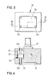
- FIG. 3 shows from below a template 20 for receiving a single flat component, such as component 10 in FIG. 1.
- the template 20 four pressing elements 21a to 21d are slidably mounted.
- a chamber 22 is formed in the template housing for each pressing element 21.
- the pressing member 21a be consists of a pin 24 and a weight 25.
- the weight 25 is located in the chamber 22 and the two ends of the pin 24 protrude up and down through openings 23o and 23u, respectively.
- the lower opening 23u opens into a recess 26.
- This recess 26 serves to receive a component.
- the template 20 has a fastening element 27, which allows a plurality of templates 20 to be strung together.
- the template is placed so that the recess 26 faces upward, and a component 10 is inserted into the recess 26 such that the flat connection contacts 12, 13 face upward (ie in FIG. 4 downward) ) point.
- the circuit board 1 is placed on the template and fastened, for example by screwing.
- the pressure elements 21 drop down in the chambers and press the component 10 onto the surface of the circuit board, namely the pins 24 engage where in the component 10 the Connection contacts are formed. It can be seen that the pressing force is approximately the same at all points on the component 10, regardless of the "height" of the component at the point in question.
- the template which is preferably made of plastic, can be designed for several components, so that an entire set of components can be applied to the circuit board at the same time.
- the template for example Can have holes or pins, by means of which the template can be screwed or clamped onto the circuit board in order to be removed quickly after the soldering process.
- the pressing elements can be designed as pins which are pressed on individually or together via spring elements.
- movable pins instead of the movable pins, other suitable means, such as temperature-resistant elastomers, can also be used within the scope of the inventive concept, with which the film elements are pressed in punctiform or flat fashion.
- suitable means such as temperature-resistant elastomers
- Such stencils can additionally be equipped with known absorbent, adhesive or similar holding devices for fixing flat components.
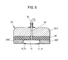
- FIG. 5 shows an embodiment of such a template 20 'with an outer template body 20A', a pressure layer 28 'consisting of an elastomer and a positioning element 20B' which surrounds a film element 10 with connection points 12, 13.
- the film element is held by vacuum generated via the bore 29 and the suction line 30.
- the layer 28 ' is pressed together.
- the templates can also remain on the circuit board after the components have been attached.
Abstract
Description
- Die vorliegende Erfindung bezieht sich auf ein Verfahren zum Befestigen von Bauelementen mit flächigen Anschlußkontakten, insbesonders von flachen, filmartigen Bauelementen, auf Leiterplatten, bei dem die Anschlußkontakte durch Löten mit der Leiterplatte verbunden werden. Die Erfindung bezieht sich ferner auf eine Schablone, die vorteilhaft bei der Ausführung dieses Verfahrens Verwendung findet.
- Bei einem bekannten Verfahren der oben genannten Art werden die Bauelemente unter Zuhilfenahme eines Lötrahmens auf der Leiterplatte verlötet. Hierzu werden die Elemente einzeln mit einer Saugpinzette in der erforderlichen Stellung auf der Leiterplatte aufgesetzt, und die Kontaktstellen werden mittels des Lötrahmens verlötet. Hierbei wird mittels des Lötrahmens die Wärme von oben durch die Elemente hindurch zu den Anschlußstellen des Elements, bzw. der Leiterplatte gebracht. Dieses Verfahren ist selbst bei maschineller Fertigung zeitintensiv, da die einzelnen Bauelemente nacheinander aufgesetzt und verlötet werden müssen.
- Es ist weiterhin bekannt, mittels einer Wärmeplatte oder Strahlern die Temperatur auf der Oberfläche einer Leiterplatte so zu steuern, daß an den gewünschten Verbindungsstellen von Leiterbahnen auf der Leiterplatte und den flächigen Anschlußkontakten der Bauelemente die Löttemperatur erreicht wird.
- In der Regel jedoch werden die Leiterplatten mit weiteren Bauelemente, welche Anschlußstifte aufweisen, bestückt, indem die Anschlußstifte auf der Rückseite der Leiterplatte in einem Lötbad verlötet werden. Der Nachteil besteht hierbei in dem zweimaligen Erwärmen der Leiterplatte, was die Zuverlässigkeit der Lötung beeinträchtigen kann und einen zusätzlichen Arbeitsgang erfordert. Elektronische Bauelemente sind zumeist sehr temperaturempfindlich. Bei Lötvorgängen muß deshalb unbedingt vermieden werden, daß kritische Grenztemperaturen der Bauteile überschritten werden, um Schäden an diesen Teilen auszuschließen. Beim Einsatz von Lötbädern darf deshalb eine bestimmte Kontaktzeit mit dem flüssigen Lot nicht überschritten werden. Flächige Bauteile können deshalb im Lötbad zusammen mit Bauelementen, welche Stifte aufweisen, nicht ohne weiteres verlötet werden, weil während der maximal zulässigen Kontaktzeit mit flüssigem Lot durch die Leiterplatte hindurch nicht genügend Wärme zum Aufschmelzen der Anschlußstellen flächiger Bauelemente zugeführt werden kann.
- Der Erfindung liegt die Aufgabe zugrunde, ein Verfahren der eingangs genannten Art anzugeben, das zuverlässiger und weniger arbeitsintensiv ist als die bekannten Verfahren.
- Diese Aufgabe wird erfindungsgemäß dadurch gelöst, daß die Leiterplatte im Bereich der Anschlußstellen der Bauelemente mit durchkontaktierten Löchern versehen wird und die Wärme zum Verschmelzen der vorhandenen Lotschichten an den Anschlagstellen der Bauelemente und der Leiterplatte von der den Bauelementen gegenüberliegenden Seite der Leiterplatte über die durchkontaktierten Löcher durch flüssiges Lot zugeführt wird.
- Dieses Verfahren bietet die Möglichkeit, eine Vielzahl von Bauelementen mit flächigen Anschlußkontakten in einem Arbeitsvorgang auf der Leiterplatte zu befestigen. Die hierdurch erzielte Zeitersparnis ist beträchtlich. Ein weiterer Vorteil dieses Verfahrens besteht darin, daß es beim maschinellen Betrieb keine aufwendigen Einrichtungen erfordert.
- Besonders vorteilhaft wird das Verfahren dann, wenn gleichzeitig flache, filmartige Bauelemente und mit durch Locher in der Leiterplatte ragenden Anschlußstiften versehene Bauelemente verlötet werden. In den meisten Fällen werden zusätzlich zu den Bauelementen mit flachen Anschlußkontakten solche mit Anschlußstiften auf der Leiterplatte zu befestigen sein. Bei dem erfindungsgemäßen Verfahren ist nur ein einziger Lütvorgang notwendig, um die einzelnen Bauelemente mit den verschiedenartigen Anschlußkontakten zu verlöten. Die Kontakte mit dem flüssigen Lot im Lötbad müssen nicht verändert werden, so daß Bauteilschäden durch Überleitung nicht auftreten.
- Ein hoher Grad an Zuverlässigkeit wird ferner dadurch erzielt, daß die Bauelemente vor dem Lötvorgang mittels einer Schablone an die Leiterplatte angelegt werden, und daß die Schablone nach Beendigen des Lötvorgangs wieder abgenommen wird. Durch Verwenden einer speziellen Schablone wird gewährleistet, daß die zu befestigenden Bauelemente richtig positioniert sind und daß die flachen Anschlußkontakte flach auf der Oberfläche der Leiterplatte aufliegen, so daß stets gewährleistet ist, daß das in den Löchern aufsteigende Lot die Anschlußkontakte erwärmt und diese verschmelzt. Werden mehrere flache Bauelemente in vorgegebener Anordnung auf einerLeiterplatte befestigt, so wird vorzugsweise eine einzige Schablone für mehrere Bauelemente verwendet, um diese gleichzeitig an die Oberfläche der Leiterplatte anzulegen oder anzudrücken.
- Eine Schablone zum Befestigen von flachen Bauelementen, insbesondere Filmelementen, auf Leiterplatten, auf denen die Bauelemente verlötet werden sollen, zeichnet sich erfindungsgemäß dadurch aus, daß in der Schablone Andrückelemente dort vorgesehen sind, wo sich Anschlußkontakte der Bauelemente befinden. Bei dieser Schablone, für die selbständiger Schutz geltend gemacht wird, werden die einzelnen Anschlußkontakte gezielt auf die Oberfläche der Leiterplatte gedrückt, wodurch ein hoher Grad an Zuverlässigkeit erreicht wird.
- Eine besonders günstige Ausführungsform einer erfindungsgemäßen Schablone sieht vor, daß die Andrückelemente als in Führungen verschiebliche Gewichte ausgebildet sind. Eine solche Schablone ist einfach herzustellen, und die Gewichte können leicht an die zu befestigenden flachen Bauelemente angepaßt werden. Die Andrückkraft ist an allen Stellen unabhängig von der jeweiligen Höhe des Bauelementes, so daß gleichmäßiger Druck an allen zu verlötenden Stellen erzielt wird. In einer Schablone können eine Vielzahl von Filmelementen aufgenommen werden.
- Im folgenden wird ein Ausführungsbeispiel der Erfindung anhand der Zeichnung näher erläutert. Es zeigen:
- Fig. 1 eine Draufsicht auf einen Ausschnitt einerLeiterplatte mit einem darauf zu befestigenden Bauelement,
- Fig. 2 einen Querschnitt der Anordnung gemäß Fig. 1 entlang der Linie II-II, die linke Kontaktstelle unverlötet, die rechte Kontaktstelle verlötet,
- Fig. 3 eine Ansicht von unten einer Schablone, die zum Andrücken eines Bauelementes an die Oberfläche einer Leiterplatte dient,
- Fig. 4 einen Querschnitt entlang der Linie IV-IV in Fig. 3 und
- Fig. 5 einen Querschnitt einer weiteren Ausführungsform einer Schablone.
- Fig. 1 zeigt einen Auschnitt einer Leiterplatte 1. Die Leiterplatte 1 ist mit mehreren durch eine Kupferschicht 2 und eine Zinnschicht 3 durchkontaktierten Löchern 4 versehen. Die Kupferschicht 2 und die Zinnschicht 3 erstrecken sich teilweise auf den Oberflächen der leiterplatte 1.
- Auf die Leiterplatte 1 ist ein einen Hall-Generator enthaltendes Hall-IC positioniert, welches von einem aus Kapton bestehenden Filmplättchen 10 gehalten wird. Wie aus Fig. 2 hervorgeht, besitzt das Bauelement 10 mehrere flächige Anschlußkontakte, jeweils bestehend aus einer Kupfer(Cu)-schicht 12 und einer Blei-Zinn-(PbSn)schicht 13.
- Um das Bauelement 10 auf der Leiterplatte 1 zu befestigen, werden zuerst die Löcher 4 mit der Durchkontaktierung hergestellt. Dieser Vorgang geschieht zweckmäßigerweise gleichzeitig mit dem Bohren und Durchkontaktieren für die anderen Bauelemente, die auf der Leiterplatte 1 zu befestigen sind und die mit Anschlußstiften versehen sind, welche in die Löcher gesteckt werden, so daß sie auf der gegenüber-liegenden Seite der Leiterplatte aus den Löchern herausragen. Sodann werden die Bauelemente 10 auf der Leiterplatte 1 positioniert. Dies geschieht vorzugsweise mittels einer noch unten zu erläuternden Schablone, in oder auf die die Bauelemente 10 mit den Anschlußkontakten nach oben gelegt werden. Die Schablone wird dann auf der Leiterplatte, beispielsweise durch Verschrauben, befestigt, so daß die Bauelemente 10 mit den Anschlußkontakten 12,13 richtig positioniert sind. Wie man bereits aus den Figuren 1 und 2 ersehen kann, besitzt die Schablone Gewichte 21a bis 21d, die auf das Filmplättchen an den Stellen der Anschlußkontakte drücken, damit die Anschlußkontakte flach auf der Leiterplattenoberfläche aufliegen. Dieser Zustand ist in Fig. 2 auf der linken Seite veranschaulicht.
- In einem weiteren Arbeitsvorgang wird die Leiterplatte mit der Unterseite durch.ein Lötbad gezogen, so daß das flüssige Lot in dem Loch 4 aufsteigt und uit der Zinnschicht der Durchkontaktierung und der Blei-Zinn-Schicht des Filmplättchens 10 verschmilzt. Hierdurch ergibt sich eine Lötstelle, die schematisch auf der rechten Seite in Fig. 2 dargestellt ist und mit dem Bezugszeichen 3' bezeichnet ist. Bei dem letzten Arbeitsvorgang sind auch die übrigen, mit Anschlußstiften versehenen Bauelemente auf der Leiterplatte verlötet worden.
- Wie man in Fig. 1 rechts unten sieht, braucht der Anschlußkontakt des Bauelements 10 nicht direkt über dem entsprechenden Loch in der Leiterplatte 4 positioniert sein, sondern es kann ein Abstand vorhanden sein. Auch in dieser Stellung erwärmt das in der Bohrung 4 aufsteigende Lot die Zinnschicht auf der Plattenoberseite so stark, daß auch hier eine gute Lötung erfolgt. Anders ausgedrückt: Für das Vprlöten der Anschlußstelle ist nicht flüssiges Fremdlot erforderlich, sondern die Wärmezufuhr erfolgt durch das flüssige Lot über die Cu-Durchkontaktierung und die Leiterbahn.
- Besonders günstige Lötergebnisse werden erzielt, wenn bei dem geschilderten Verfahren die Bohrungen 4 mit einem Durchmesser zwischen 0,3 und 1,6 mm ausgebildet werden.
- Fig. 3 zeigt von unten eine Schablone 20 zum-Aufnehmen eines einzelnen flachen Bauelements, wie beispielsweise des Bauelements 10 in Fig. 1. In der Schablone 20 sind vier Andrückelemente 21a bis 21d verschieblich gelagert. Wie aus Fig. 4 hervorgeht, ist für jedes Andrückelement 21 eine Kammer 22 in dem Schablonengehäuse ausgebildet. Das Andrückelement 21a besteht aus einem Stift 24 und einem Gewicht 25. Das Gewicht 25 befindet sich inder Kammer 22, und die beiden Enden des Stiftes 24 ragen nach oben und unten durch eine Öffnung 23o bzw. 23u. Die untere Öffnung 23u mündet in eine Aussparung 26. Diese Aussparung 26 dient zur Aufnahme eines Bauelements. Weiterhin besitzt die Schablone 20 ein Befestigungselement 27, welches das Aneinanderreihen mehrerer Schablonen 20 gestattet.
- Zum Befestigen beispielsweise des Bauelements 10 wird die Schablone so gelegt, daß die Aussparung 26 nach oben weist, und ein Bauelement 10 wird so in die Aussparung 26 eingelegt, daß die flächigen Anschlußkontakte 12,13 nach oben, (d.h. in Fig. 4 nach unten) weisen. Dann wird die Leiterplatte 1 auf die Schablone gelegt und befestigt, beispielsweise durch Verschrauben. Wenn die Leiterplatte mit der den Bauelementen gegenüberliegenden Seite durch ein Lötbad gezogen wird, fallen die Andrückelemente 21 in den Kammern nach unten und drücken das Bauelement 10 auf die Oberfläche der Leiterplatte, und zwar greifen die Stifte 24 dort an, wo in dem Bauelement 10 die Anschlußkontakte ausgebildet sind. Man sieht, daß die Andrückkraft an allen Stellen des Bauelements 10 etwa gleich groß ist, unabhängig von der "Höhe" des Bauelements an der betreffenden Stelle.
- Die Erfindung ist nicht auf das dargestellt Ausführungsbeispiel beschränkt. Grundsätzlich können nach dem er= findungsgemäßen Verfahren sämtliche mit flächigenAnschlußkontakten versehene Bauelemente auf einer Leiterplatte verlötet werden. Selbstverständlich kann die Schablone, die vorzugsweise aus Kunststoff besteht, für mehrere Bauelemente ausgelegt werden, so daß gleichzeitig ein ganzer Satz von Bauelementen auf die Leiterplatte aufgebracht werden kann. Obschon dies nicht in der Zeichnung dargestellt wurde, dürfte es für den Fachmann klar sein, daß die Schablone beispielsweise Bohrungen oder Stifte aufweisen kann, mittels derer die Schablone auf der Leiterplatte -festgeschraubt oder geklemmt werden kann, um nach dem Lötvorgang rasch abgenommen werden zu können. Ebenso können die Andrückelemente anstelle der in Führungen verschiebbaren Gewichte als Stifte ausgebildet werden die einzeln oder gemeinsam über Federelemente angedrückt werden. Anstelle der beweglichen Stifte können im Rahmen des Erfindungsgedankens auch andere geeignete Mittel wie temperaturbeständige Elastomere verwendet werden, mit denen punktförmig oder flächig die Filmelemente angedrückt werden. Solche Schablonen können zusätzlich mit bekannten saugenden, klebenden oder ähnlichen Halteeinrichtungen zum Fixieren flächiger Bauteile ausgerüstet sein.
- Fig. 5 zeigt ein Ausführungsbeispiel einer solchen Schablone 20' mit einem äußeren Schablonenkörper 20A', einer aus einem Elastomer bestehenden Andrückschicht 28' und einem Positionierelement 20B', welches ein Filmelement 10 mit Anschlußstellen 12,13 umgibt. Das Filmelement wird nach dem Einlegen durch über dieBohrung 29 und die Saugleitung 30 erzeugtes Vakuum gehalten. Beim Andrücken des Filmelements auf die Leiterplatte wird die Schicht 28' zusammengedrückt.
- In bestimmten Anwendungsfällen können die Schablonen auch auf der Leiterplatte verbleiben, nachdem die Bauelemente befestigt sind.
Claims (9)
Priority Applications (1)
| Application Number | Priority Date | Filing Date | Title |
|---|---|---|---|
| AT79104855T ATE320T1 (de) | 1978-12-06 | 1979-12-03 | Verfahren und schablone zum befestigen von bauelementen mit flaechigen anschlusskontakten auf leiterplatten. |
Applications Claiming Priority (2)
| Application Number | Priority Date | Filing Date | Title |
|---|---|---|---|
| DE2852753A DE2852753C3 (de) | 1978-12-06 | 1978-12-06 | Verfahren zum Befestigen von Bauelementen mit flächigen Anschlußkontakten auf einer Leiterplatte und Schablone zur Durchführung des Verfahrens |
| DE2852753 | 1978-12-06 |
Publications (3)
| Publication Number | Publication Date |
|---|---|
| EP0012319A1 true EP0012319A1 (de) | 1980-06-25 |
| EP0012319B1 EP0012319B1 (de) | 1981-10-21 |
| EP0012319B2 EP0012319B2 (de) | 1986-01-02 |
Family
ID=6056465
Family Applications (1)
| Application Number | Title | Priority Date | Filing Date |
|---|---|---|---|
| EP79104855A Expired EP0012319B2 (de) | 1978-12-06 | 1979-12-03 | Verfahren und Schablone zum Befestigen von Bauelementen mit flächigen Anschlusskontakten auf Leiterplatten |
Country Status (4)
| Country | Link |
|---|---|
| US (1) | US4373259A (de) |
| EP (1) | EP0012319B2 (de) |
| AT (1) | ATE320T1 (de) |
| DE (1) | DE2852753C3 (de) |
Cited By (2)
| Publication number | Priority date | Publication date | Assignee | Title |
|---|---|---|---|---|
| WO1985000085A1 (en) * | 1983-06-15 | 1985-01-03 | Walter Kundler | Printed board for the surface soldering of integrated miniature circuits and manufacturing method of such printed boards |
| GB2210818A (en) * | 1987-10-10 | 1989-06-21 | Plessey Co Plc | A process for soldering a component to a printed circuit board |
Families Citing this family (26)
| Publication number | Priority date | Publication date | Assignee | Title |
|---|---|---|---|---|
| JPS57205179U (de) * | 1981-06-24 | 1982-12-27 | ||
| DE3231056A1 (de) * | 1982-08-20 | 1984-02-23 | Siemens AG, 1000 Berlin und 8000 München | Verfahren zum aufbringen von unbedrahteten bauelementen auf leiterplatten |
| JPS5998591A (ja) * | 1982-11-27 | 1984-06-06 | 松下電器産業株式会社 | 両面回路接続方法 |
| GB8403968D0 (en) * | 1984-02-15 | 1984-03-21 | Heraeus Gmbh W C | Chip resistors |
| DE3406528A1 (de) * | 1984-02-23 | 1985-08-29 | Brown, Boveri & Cie Ag, 6800 Mannheim | Leistungshalbleitermodul |
| DE3440668A1 (de) * | 1984-11-07 | 1986-05-07 | Dr.-Ing. Max Schlötter GmbH & Co KG, 7340 Geislingen | Verfahren zur erhaltung der loetbarkeit von bleizinn-ueberzuegen |
| US4727633A (en) * | 1985-08-08 | 1988-03-01 | Tektronix, Inc. | Method of securing metallic members together |
| EP0222038B1 (de) * | 1985-11-13 | 1989-05-10 | C.A. Weidmüller GmbH & Co. | Reihenklemme |
| US4761881A (en) * | 1986-09-15 | 1988-08-09 | International Business Machines Corporation | Single step solder process |
| DE3730497A1 (de) * | 1987-09-11 | 1989-03-30 | Philips Patentverwaltung | Oberflaechenmontierbares bauelement |
| US4877176A (en) * | 1987-11-25 | 1989-10-31 | Northern Telecom Limited | Soldering pins into printed circuit boards |
| US4893216A (en) * | 1988-08-09 | 1990-01-09 | Northern Telecom Limited | Circuit board and method of soldering |
| DE3843984A1 (de) * | 1988-12-27 | 1990-07-05 | Asea Brown Boveri | Verfahren zum loeten eines drahtlosen bauelementes sowie leiterplatte mit angeloetetem, drahtlosem bauelement |
| US4916807A (en) * | 1989-01-05 | 1990-04-17 | Wiese Paul H | Method and apparatus for assembling circuits having surface mounted components |
| US4982376A (en) * | 1989-04-20 | 1991-01-01 | U.S. Philips Corporation | Method of mounting electrical and/or electronic components on a single-sided printed board |
| US5059105A (en) * | 1989-10-23 | 1991-10-22 | Motorola, Inc. | Resilient mold assembly |
| US5071359A (en) * | 1990-04-27 | 1991-12-10 | Rogers Corporation | Array connector |
| US5245751A (en) * | 1990-04-27 | 1993-09-21 | Circuit Components, Incorporated | Array connector |
| US5270903A (en) * | 1990-09-10 | 1993-12-14 | Codex Corporation | Printed circuit board manufacturing method accommodates wave soldering and press fitting of components |
| DE4234418A1 (de) * | 1992-10-13 | 1994-04-14 | Thomson Brandt Gmbh | Justiervorrichtung |
| DE4319876A1 (de) * | 1993-02-26 | 1994-09-01 | Siemens Ag | Verfahren zum Befestigen einer Hybrid-Schaltung auf einer Leiterplatte |
| US5773195A (en) * | 1994-12-01 | 1998-06-30 | International Business Machines Corporation | Cap providing flat surface for DCA and solder ball attach and for sealing plated through holes, multi-layer electronic structures including the cap, and a process of forming the cap and for forming multi-layer electronic structures including the cap |
| US6112406A (en) * | 1996-05-06 | 2000-09-05 | Siemens Aktiengesellschaft | Method for producing electrically conductive connections between two or more conductor structures |
| US7473218B2 (en) * | 2002-08-06 | 2009-01-06 | Olympus Corporation | Assembling method of capsule medical apparatus |
| JP2007180447A (ja) * | 2005-12-28 | 2007-07-12 | Toyota Industries Corp | 半田付け方法、半田付け装置、及び半導体装置の製造方法 |
| CN112171061B (zh) * | 2020-09-29 | 2022-06-07 | 大连优迅科技股份有限公司 | 用于qsp28模块柔性软板的焊接组装夹具 |
Citations (5)
| Publication number | Priority date | Publication date | Assignee | Title |
|---|---|---|---|---|
| DE1089437B (de) * | 1957-05-27 | 1960-09-22 | Gen Electric | Verfahren zur Bestueckung von Traegern mit flaechenhafter Leitungsfuehrung |
| DE1194681B (de) * | 1962-05-10 | 1965-06-10 | Philips Patentverwaltung | Vorrichtung zum Verloeten von ebenen Leiterzugplatten mit den Anschlussdraehten von auf die Platten aufgesetzten Bauteilen |
| FR1484521A (fr) * | 1965-06-24 | 1967-06-09 | Texas Instruments Inc | Dispositif de montage de composants dans un circuit électronique |
| US3516155A (en) * | 1967-02-02 | 1970-06-23 | Bunker Ramo | Method and apparatus for assembling electrical components |
| DE2640613A1 (de) * | 1976-09-09 | 1978-03-16 | Siemens Ag | Verfahren und vorrichtung zum kontaktieren von schaltungsbausteinen in eine schichtschaltung |
Family Cites Families (16)
| Publication number | Priority date | Publication date | Assignee | Title |
|---|---|---|---|---|
| US3302067A (en) * | 1967-01-31 | Modular circuit package utilizing solder coated | ||
| DE1065898B (de) * | 1959-09-24 | |||
| US2756485A (en) * | 1950-08-28 | 1956-07-31 | Abramson Moe | Process of assembling electrical circuits |
| DE1616732B1 (de) | 1962-05-11 | 1970-08-20 | Ibm | In Mikromodultechnik ausgefuehrte elektrische Schaltung |
| US3294951A (en) * | 1963-04-30 | 1966-12-27 | United Aircraft Corp | Micro-soldering |
| US3393449A (en) * | 1963-11-01 | 1968-07-23 | Itt | Method of assembly of resistor matrix |
| US3355078A (en) * | 1964-11-23 | 1967-11-28 | Bunker Ramo | Apparatus for assembling electrical components |
| US3387365A (en) * | 1965-09-28 | 1968-06-11 | John P. Stelmak | Method of making electrical connections to a miniature electronic component |
| US3540718A (en) * | 1966-08-22 | 1970-11-17 | Robert E Heffron | Printed circuit board component clamp and assembly jig |
| US3445919A (en) * | 1968-07-11 | 1969-05-27 | Electronic Eng Co California | Method of using a solder contact fluid |
| US3690943A (en) * | 1970-04-24 | 1972-09-12 | Rca Corp | Method of alloying two metals |
| US3673680A (en) * | 1970-12-14 | 1972-07-04 | California Computer Products | Method of circuit board with solder coated pattern |
| US3762040A (en) * | 1971-10-06 | 1973-10-02 | Western Electric Co | Method of forming circuit crossovers |
| US3982979A (en) * | 1973-06-28 | 1976-09-28 | Western Electric Company, Inc. | Methods for mounting an article on an adherent site on a substrate |
| DE2633269C2 (de) * | 1976-07-23 | 1978-04-06 | Siemens Ag, 1000 Berlin Und 8000 Muenchen | Verfahren zum Anlöten von Bauelementen an metallisierte Bereiche eines Schichtschaltungssubstrates |
| DE2657313B2 (de) | 1976-12-17 | 1978-10-12 | Siemens Ag, 1000 Berlin Und 8000 Muenchen | Verfahren zum Verbinden elektrischer Bauelemente mit den Leiterbahnen einer Leiter- oder Trägerplatte |
-
1978
- 1978-12-06 DE DE2852753A patent/DE2852753C3/de not_active Expired
-
1979
- 1979-12-03 AT AT79104855T patent/ATE320T1/de not_active IP Right Cessation
- 1979-12-03 EP EP79104855A patent/EP0012319B2/de not_active Expired
- 1979-12-05 US US06/100,354 patent/US4373259A/en not_active Expired - Lifetime
Patent Citations (5)
| Publication number | Priority date | Publication date | Assignee | Title |
|---|---|---|---|---|
| DE1089437B (de) * | 1957-05-27 | 1960-09-22 | Gen Electric | Verfahren zur Bestueckung von Traegern mit flaechenhafter Leitungsfuehrung |
| DE1194681B (de) * | 1962-05-10 | 1965-06-10 | Philips Patentverwaltung | Vorrichtung zum Verloeten von ebenen Leiterzugplatten mit den Anschlussdraehten von auf die Platten aufgesetzten Bauteilen |
| FR1484521A (fr) * | 1965-06-24 | 1967-06-09 | Texas Instruments Inc | Dispositif de montage de composants dans un circuit électronique |
| US3516155A (en) * | 1967-02-02 | 1970-06-23 | Bunker Ramo | Method and apparatus for assembling electrical components |
| DE2640613A1 (de) * | 1976-09-09 | 1978-03-16 | Siemens Ag | Verfahren und vorrichtung zum kontaktieren von schaltungsbausteinen in eine schichtschaltung |
Cited By (2)
| Publication number | Priority date | Publication date | Assignee | Title |
|---|---|---|---|---|
| WO1985000085A1 (en) * | 1983-06-15 | 1985-01-03 | Walter Kundler | Printed board for the surface soldering of integrated miniature circuits and manufacturing method of such printed boards |
| GB2210818A (en) * | 1987-10-10 | 1989-06-21 | Plessey Co Plc | A process for soldering a component to a printed circuit board |
Also Published As
| Publication number | Publication date |
|---|---|
| EP0012319B2 (de) | 1986-01-02 |
| DE2852753A1 (de) | 1980-06-12 |
| US4373259A (en) | 1983-02-15 |
| ATE320T1 (de) | 1981-11-15 |
| DE2852753B2 (de) | 1980-11-06 |
| DE2852753C3 (de) | 1985-06-20 |
| EP0012319B1 (de) | 1981-10-21 |
Similar Documents
| Publication | Publication Date | Title |
|---|---|---|
| EP0012319B1 (de) | Verfahren und Schablone zum Befestigen von Bauelementen mit flächigen Anschlusskontakten auf Leiterplatten | |
| DE3236229A1 (de) | Vorrichtung und verfahren zum befestigen von baugruppen mit integrierter schaltung auf einer gedruckten schaltungsplatte | |
| DE4203605A1 (de) | Elektrischer verbinder | |
| EP0092086B1 (de) | Anschlussvorrichtung für ein plattenförmiges elektrisches Gerät | |
| DE4208536A1 (de) | Verfahren zum miteinander verbinden eines fluessigkristallanzeigeelements und einer flexiblen schaltungsplatte | |
| DE10126655A1 (de) | Leiterplatte mit mindestens einem elektronischen Bauteil | |
| DE2640613C2 (de) | Verfahren und Vorrichtung zum Kontaktieren von Schaltungsbausteinen in eine Schichtschaltung | |
| EP0420050B1 (de) | Verfahren zum Auflöten von Bauelementen auf Leiterplatten | |
| EP1665914A1 (de) | Leiterplatte mit einer haltevorrichtung zum halten bedrahteter elektronischer bauteile, verfahren zur herstellung einer solchen leiterplatte und deren verwendung in einem lötofen | |
| EP1393604A1 (de) | Leiterplatte mit einer darauf aufgebrachten kontakthülse | |
| DE3827473A1 (de) | Leiterplatte zum bestuecken mit smd-bausteinen | |
| EP0613331A1 (de) | Verfahren zum Befestigen einer Hybrid-Schaltung auf einer Leiterplatte | |
| DE10059808A1 (de) | Verfahren zur Verbindung einer integrierten Schaltung und einer flexiblen Schaltung | |
| DE3303951A1 (de) | Bestueckungstisch zum manuellen bestuecken von schaltungstraegern | |
| DE4204882C2 (de) | Vorrichtung und Verfahren zum Bestücken von oberflächenmontierbaren Bauelementen mit kleinen Kontaktabständen | |
| DE3925155C2 (de) | ||
| EP0378113A2 (de) | Lötvorrichtung mit mindestens einer Bügelelektrode | |
| WO2006018351A1 (de) | Leiterplatte mit wenigstens einem thermisch kritischen smd-bauteil und verfahren zum herstellen, bestücken und löten einer leiterplatte | |
| DE3824314A1 (de) | Verbindungselement oder fassung nach dem ssc-prinzip | |
| DE19610586B4 (de) | Leiterplatte und lagegenauen Bestücken und Löten von elektronischen Bauelementen auf der Oberfläche der Leiterplatte | |
| EP1111974B1 (de) | Verfahren zur Herstellung einer Lötverbindung | |
| DE4028978A1 (de) | Loetkontaktelement fuer leiterplatten zur verloetung von oberflaechenmontierbaren smd-bauteilen, und bevorzugte verwendung desselben zur verloetung von uebereinanderliegenden bauteilen | |
| WO2024061851A1 (de) | Verfahren und vorrichtung zum elektrischen kontaktieren von elektronischen bauelementen | |
| DE4438449A1 (de) | Verfahren zur direkten Kontaktierung elektronischer Bauelemente mit einem Träger und direkt kontaktierbare Bauelemente hierzu | |
| DE2023569B2 (de) | Verfahren zur Verbindung von zwei Leiterbahnen einer gedruckten Schaltungsplatte |
Legal Events
| Date | Code | Title | Description |
|---|---|---|---|
| PUAI | Public reference made under article 153(3) epc to a published international application that has entered the european phase |
Free format text: ORIGINAL CODE: 0009012 |
|
| AK | Designated contracting states |
Designated state(s): AT BE CH FR GB IT LU NL SE |
|
| 17P | Request for examination filed | ||
| ITF | It: translation for a ep patent filed |
Owner name: PATRITO BREVETTI |
|
| GRAA | (expected) grant |
Free format text: ORIGINAL CODE: 0009210 |
|
| AK | Designated contracting states |
Designated state(s): AT BE CH FR GB IT LU NL SE |
|
| REF | Corresponds to: |
Ref document number: 320 Country of ref document: AT Date of ref document: 19811115 Kind code of ref document: T |
|
| PG25 | Lapsed in a contracting state [announced via postgrant information from national office to epo] |
Ref country code: LU Free format text: LAPSE BECAUSE OF NON-PAYMENT OF DUE FEES Effective date: 19811231 |
|
| PLBI | Opposition filed |
Free format text: ORIGINAL CODE: 0009260 |
|
| 26 | Opposition filed |
Opponent name: N.V. PHILIPS' GLOEILAMPENFABRIEKEN Effective date: 19820720 |
|
| PGFP | Annual fee paid to national office [announced via postgrant information from national office to epo] |
Ref country code: CH Payment date: 19840110 Year of fee payment: 5 |
|
| PGFP | Annual fee paid to national office [announced via postgrant information from national office to epo] |
Ref country code: LU Payment date: 19840117 Year of fee payment: 5 |
|
| PGFP | Annual fee paid to national office [announced via postgrant information from national office to epo] |
Ref country code: BE Payment date: 19840331 Year of fee payment: 5 |
|
| PGFP | Annual fee paid to national office [announced via postgrant information from national office to epo] |
Ref country code: FR Payment date: 19841217 Year of fee payment: 6 |
|
| PGFP | Annual fee paid to national office [announced via postgrant information from national office to epo] |
Ref country code: SE Payment date: 19841231 Year of fee payment: 6 |
|
| PUAH | Patent maintained in amended form |
Free format text: ORIGINAL CODE: 0009272 |
|
| STAA | Information on the status of an ep patent application or granted ep patent |
Free format text: STATUS: PATENT MAINTAINED AS AMENDED |
|
| 27A | Patent maintained in amended form | ||
| AK | Designated contracting states |
Kind code of ref document: B2 Designated state(s): AT BE CH FR GB IT LU NL SE |
|
| ITF | It: translation for a ep patent filed |
Owner name: PATRITO BREVETTI |
|
| NLR2 | Nl: decision of opposition | ||
| ET3 | Fr: translation filed ** decision concerning opposition | ||
| NLR3 | Nl: receipt of modified translations in the netherlands language after an opposition procedure | ||
| PGFP | Annual fee paid to national office [announced via postgrant information from national office to epo] |
Ref country code: AT Payment date: 19861203 Year of fee payment: 8 |
|
| PGFP | Annual fee paid to national office [announced via postgrant information from national office to epo] |
Ref country code: NL Payment date: 19861231 Year of fee payment: 8 |
|
| PG25 | Lapsed in a contracting state [announced via postgrant information from national office to epo] |
Ref country code: AT Effective date: 19871203 |
|
| PG25 | Lapsed in a contracting state [announced via postgrant information from national office to epo] |
Ref country code: SE Effective date: 19871204 |
|
| PG25 | Lapsed in a contracting state [announced via postgrant information from national office to epo] |
Ref country code: CH Effective date: 19871231 Ref country code: BE Effective date: 19871231 |
|
| BERE | Be: lapsed |
Owner name: WURTTEMBERGISCHE METALLWARENFABRIK A.G. Effective date: 19871231 |
|
| PG25 | Lapsed in a contracting state [announced via postgrant information from national office to epo] |
Ref country code: NL Effective date: 19880701 |
|
| NLV4 | Nl: lapsed or anulled due to non-payment of the annual fee | ||
| GBPC | Gb: european patent ceased through non-payment of renewal fee | ||
| PG25 | Lapsed in a contracting state [announced via postgrant information from national office to epo] |
Ref country code: FR Free format text: LAPSE BECAUSE OF NON-PAYMENT OF DUE FEES Effective date: 19880831 |
|
| REG | Reference to a national code |
Ref country code: CH Ref legal event code: PL |
|
| REG | Reference to a national code |
Ref country code: FR Ref legal event code: ST |
|
| PG25 | Lapsed in a contracting state [announced via postgrant information from national office to epo] |
Ref country code: GB Free format text: LAPSE BECAUSE OF NON-PAYMENT OF DUE FEES Effective date: 19881118 |
|
| EUG | Se: european patent has lapsed |
Ref document number: 79104855.6 Effective date: 19880912 |
|
| APAC | Appeal dossier modified |
Free format text: ORIGINAL CODE: EPIDOS NOAPO |
|
| APAC | Appeal dossier modified |
Free format text: ORIGINAL CODE: EPIDOS NOAPO |