EP0021421A1 - Prosthetic joint - Google Patents
Prosthetic joint Download PDFInfo
- Publication number
- EP0021421A1 EP0021421A1 EP80103598A EP80103598A EP0021421A1 EP 0021421 A1 EP0021421 A1 EP 0021421A1 EP 80103598 A EP80103598 A EP 80103598A EP 80103598 A EP80103598 A EP 80103598A EP 0021421 A1 EP0021421 A1 EP 0021421A1
- Authority
- EP
- European Patent Office
- Prior art keywords
- bearing
- bearing surface
- platform
- component
- joint
- Prior art date
- Legal status (The legal status is an assumption and is not a legal conclusion. Google has not performed a legal analysis and makes no representation as to the accuracy of the status listed.)
- Granted
Links
Images


Classifications
-
- A—HUMAN NECESSITIES
- A61—MEDICAL OR VETERINARY SCIENCE; HYGIENE
- A61F—FILTERS IMPLANTABLE INTO BLOOD VESSELS; PROSTHESES; DEVICES PROVIDING PATENCY TO, OR PREVENTING COLLAPSING OF, TUBULAR STRUCTURES OF THE BODY, e.g. STENTS; ORTHOPAEDIC, NURSING OR CONTRACEPTIVE DEVICES; FOMENTATION; TREATMENT OR PROTECTION OF EYES OR EARS; BANDAGES, DRESSINGS OR ABSORBENT PADS; FIRST-AID KITS
- A61F2/00—Filters implantable into blood vessels; Prostheses, i.e. artificial substitutes or replacements for parts of the body; Appliances for connecting them with the body; Devices providing patency to, or preventing collapsing of, tubular structures of the body, e.g. stents
- A61F2/02—Prostheses implantable into the body
- A61F2/30—Joints
- A61F2/38—Joints for elbows or knees
- A61F2/3868—Joints for elbows or knees with sliding tibial bearing
-
- A—HUMAN NECESSITIES
- A61—MEDICAL OR VETERINARY SCIENCE; HYGIENE
- A61F—FILTERS IMPLANTABLE INTO BLOOD VESSELS; PROSTHESES; DEVICES PROVIDING PATENCY TO, OR PREVENTING COLLAPSING OF, TUBULAR STRUCTURES OF THE BODY, e.g. STENTS; ORTHOPAEDIC, NURSING OR CONTRACEPTIVE DEVICES; FOMENTATION; TREATMENT OR PROTECTION OF EYES OR EARS; BANDAGES, DRESSINGS OR ABSORBENT PADS; FIRST-AID KITS
- A61F2/00—Filters implantable into blood vessels; Prostheses, i.e. artificial substitutes or replacements for parts of the body; Appliances for connecting them with the body; Devices providing patency to, or preventing collapsing of, tubular structures of the body, e.g. stents
- A61F2/02—Prostheses implantable into the body
- A61F2/30—Joints
- A61F2/42—Joints for wrists or ankles; for hands, e.g. fingers; for feet, e.g. toes
- A61F2/4202—Joints for wrists or ankles; for hands, e.g. fingers; for feet, e.g. toes for ankles
-
- A—HUMAN NECESSITIES
- A61—MEDICAL OR VETERINARY SCIENCE; HYGIENE
- A61F—FILTERS IMPLANTABLE INTO BLOOD VESSELS; PROSTHESES; DEVICES PROVIDING PATENCY TO, OR PREVENTING COLLAPSING OF, TUBULAR STRUCTURES OF THE BODY, e.g. STENTS; ORTHOPAEDIC, NURSING OR CONTRACEPTIVE DEVICES; FOMENTATION; TREATMENT OR PROTECTION OF EYES OR EARS; BANDAGES, DRESSINGS OR ABSORBENT PADS; FIRST-AID KITS
- A61F2/00—Filters implantable into blood vessels; Prostheses, i.e. artificial substitutes or replacements for parts of the body; Appliances for connecting them with the body; Devices providing patency to, or preventing collapsing of, tubular structures of the body, e.g. stents
- A61F2/02—Prostheses implantable into the body
- A61F2/30—Joints
- A61F2/38—Joints for elbows or knees
- A61F2/3877—Patellae or trochleae
-
- A—HUMAN NECESSITIES
- A61—MEDICAL OR VETERINARY SCIENCE; HYGIENE
- A61F—FILTERS IMPLANTABLE INTO BLOOD VESSELS; PROSTHESES; DEVICES PROVIDING PATENCY TO, OR PREVENTING COLLAPSING OF, TUBULAR STRUCTURES OF THE BODY, e.g. STENTS; ORTHOPAEDIC, NURSING OR CONTRACEPTIVE DEVICES; FOMENTATION; TREATMENT OR PROTECTION OF EYES OR EARS; BANDAGES, DRESSINGS OR ABSORBENT PADS; FIRST-AID KITS
- A61F2/00—Filters implantable into blood vessels; Prostheses, i.e. artificial substitutes or replacements for parts of the body; Appliances for connecting them with the body; Devices providing patency to, or preventing collapsing of, tubular structures of the body, e.g. stents
- A61F2/02—Prostheses implantable into the body
- A61F2/30—Joints
- A61F2002/30001—Additional features of subject-matter classified in A61F2/28, A61F2/30 and subgroups thereof
- A61F2002/30108—Shapes
- A61F2002/3011—Cross-sections or two-dimensional shapes
- A61F2002/30159—Concave polygonal shapes
- A61F2002/30176—V-shaped
-
- A—HUMAN NECESSITIES
- A61—MEDICAL OR VETERINARY SCIENCE; HYGIENE
- A61F—FILTERS IMPLANTABLE INTO BLOOD VESSELS; PROSTHESES; DEVICES PROVIDING PATENCY TO, OR PREVENTING COLLAPSING OF, TUBULAR STRUCTURES OF THE BODY, e.g. STENTS; ORTHOPAEDIC, NURSING OR CONTRACEPTIVE DEVICES; FOMENTATION; TREATMENT OR PROTECTION OF EYES OR EARS; BANDAGES, DRESSINGS OR ABSORBENT PADS; FIRST-AID KITS
- A61F2/00—Filters implantable into blood vessels; Prostheses, i.e. artificial substitutes or replacements for parts of the body; Appliances for connecting them with the body; Devices providing patency to, or preventing collapsing of, tubular structures of the body, e.g. stents
- A61F2/02—Prostheses implantable into the body
- A61F2/30—Joints
- A61F2/30767—Special external or bone-contacting surface, e.g. coating for improving bone ingrowth
- A61F2/30771—Special external or bone-contacting surface, e.g. coating for improving bone ingrowth applied in original prostheses, e.g. holes or grooves
- A61F2002/30878—Special external or bone-contacting surface, e.g. coating for improving bone ingrowth applied in original prostheses, e.g. holes or grooves with non-sharp protrusions, for instance contacting the bone for anchoring, e.g. keels, pegs, pins, posts, shanks, stems, struts
- A61F2002/30879—Ribs
-
- A—HUMAN NECESSITIES
- A61—MEDICAL OR VETERINARY SCIENCE; HYGIENE
- A61F—FILTERS IMPLANTABLE INTO BLOOD VESSELS; PROSTHESES; DEVICES PROVIDING PATENCY TO, OR PREVENTING COLLAPSING OF, TUBULAR STRUCTURES OF THE BODY, e.g. STENTS; ORTHOPAEDIC, NURSING OR CONTRACEPTIVE DEVICES; FOMENTATION; TREATMENT OR PROTECTION OF EYES OR EARS; BANDAGES, DRESSINGS OR ABSORBENT PADS; FIRST-AID KITS
- A61F2/00—Filters implantable into blood vessels; Prostheses, i.e. artificial substitutes or replacements for parts of the body; Appliances for connecting them with the body; Devices providing patency to, or preventing collapsing of, tubular structures of the body, e.g. stents
- A61F2/02—Prostheses implantable into the body
- A61F2/30—Joints
- A61F2/30767—Special external or bone-contacting surface, e.g. coating for improving bone ingrowth
- A61F2/30771—Special external or bone-contacting surface, e.g. coating for improving bone ingrowth applied in original prostheses, e.g. holes or grooves
- A61F2002/30878—Special external or bone-contacting surface, e.g. coating for improving bone ingrowth applied in original prostheses, e.g. holes or grooves with non-sharp protrusions, for instance contacting the bone for anchoring, e.g. keels, pegs, pins, posts, shanks, stems, struts
- A61F2002/30884—Fins or wings, e.g. longitudinal wings for preventing rotation within the bone cavity
-
- A—HUMAN NECESSITIES
- A61—MEDICAL OR VETERINARY SCIENCE; HYGIENE
- A61F—FILTERS IMPLANTABLE INTO BLOOD VESSELS; PROSTHESES; DEVICES PROVIDING PATENCY TO, OR PREVENTING COLLAPSING OF, TUBULAR STRUCTURES OF THE BODY, e.g. STENTS; ORTHOPAEDIC, NURSING OR CONTRACEPTIVE DEVICES; FOMENTATION; TREATMENT OR PROTECTION OF EYES OR EARS; BANDAGES, DRESSINGS OR ABSORBENT PADS; FIRST-AID KITS
- A61F2/00—Filters implantable into blood vessels; Prostheses, i.e. artificial substitutes or replacements for parts of the body; Appliances for connecting them with the body; Devices providing patency to, or preventing collapsing of, tubular structures of the body, e.g. stents
- A61F2/02—Prostheses implantable into the body
- A61F2/30—Joints
- A61F2/30767—Special external or bone-contacting surface, e.g. coating for improving bone ingrowth
- A61F2/30771—Special external or bone-contacting surface, e.g. coating for improving bone ingrowth applied in original prostheses, e.g. holes or grooves
- A61F2002/30904—Special external or bone-contacting surface, e.g. coating for improving bone ingrowth applied in original prostheses, e.g. holes or grooves serrated profile, i.e. saw-toothed
-
- A—HUMAN NECESSITIES
- A61—MEDICAL OR VETERINARY SCIENCE; HYGIENE
- A61F—FILTERS IMPLANTABLE INTO BLOOD VESSELS; PROSTHESES; DEVICES PROVIDING PATENCY TO, OR PREVENTING COLLAPSING OF, TUBULAR STRUCTURES OF THE BODY, e.g. STENTS; ORTHOPAEDIC, NURSING OR CONTRACEPTIVE DEVICES; FOMENTATION; TREATMENT OR PROTECTION OF EYES OR EARS; BANDAGES, DRESSINGS OR ABSORBENT PADS; FIRST-AID KITS
- A61F2/00—Filters implantable into blood vessels; Prostheses, i.e. artificial substitutes or replacements for parts of the body; Appliances for connecting them with the body; Devices providing patency to, or preventing collapsing of, tubular structures of the body, e.g. stents
- A61F2/02—Prostheses implantable into the body
- A61F2/30—Joints
- A61F2/38—Joints for elbows or knees
- A61F2/3877—Patellae or trochleae
- A61F2002/3881—Patellae or trochleae with moving parts
-
- A—HUMAN NECESSITIES
- A61—MEDICAL OR VETERINARY SCIENCE; HYGIENE
- A61F—FILTERS IMPLANTABLE INTO BLOOD VESSELS; PROSTHESES; DEVICES PROVIDING PATENCY TO, OR PREVENTING COLLAPSING OF, TUBULAR STRUCTURES OF THE BODY, e.g. STENTS; ORTHOPAEDIC, NURSING OR CONTRACEPTIVE DEVICES; FOMENTATION; TREATMENT OR PROTECTION OF EYES OR EARS; BANDAGES, DRESSINGS OR ABSORBENT PADS; FIRST-AID KITS
- A61F2/00—Filters implantable into blood vessels; Prostheses, i.e. artificial substitutes or replacements for parts of the body; Appliances for connecting them with the body; Devices providing patency to, or preventing collapsing of, tubular structures of the body, e.g. stents
- A61F2/02—Prostheses implantable into the body
- A61F2/30—Joints
- A61F2/38—Joints for elbows or knees
- A61F2002/3895—Joints for elbows or knees unicompartimental
-
- A—HUMAN NECESSITIES
- A61—MEDICAL OR VETERINARY SCIENCE; HYGIENE
- A61F—FILTERS IMPLANTABLE INTO BLOOD VESSELS; PROSTHESES; DEVICES PROVIDING PATENCY TO, OR PREVENTING COLLAPSING OF, TUBULAR STRUCTURES OF THE BODY, e.g. STENTS; ORTHOPAEDIC, NURSING OR CONTRACEPTIVE DEVICES; FOMENTATION; TREATMENT OR PROTECTION OF EYES OR EARS; BANDAGES, DRESSINGS OR ABSORBENT PADS; FIRST-AID KITS
- A61F2230/00—Geometry of prostheses classified in groups A61F2/00 - A61F2/26 or A61F2/82 or A61F9/00 or A61F11/00 or subgroups thereof
- A61F2230/0002—Two-dimensional shapes, e.g. cross-sections
- A61F2230/0028—Shapes in the form of latin or greek characters
- A61F2230/0054—V-shaped
Definitions
- This invention relates to a prosthetic joint, particularly to a prosthesis for replacement of.a dysfunctional knee joint.
- prior art knee endoprostheses and in particular to the prior art knee prostheses with patello-femoral replacement, it has been observed that such prior art prostheses have poorly designed patello-femoral interfaces in that they do not provide reasonablecongruentpatello-femoral contact or sliding engagement over any appreciable range of knee motion.
- such prior art prostheses typically produce contact stresses which result in yielding and fatigue of the plastic bearing surface typically present in such prostheses.
- This result is caused by the fact that the bearing surface of the femoral component, over which the patella prosthesis must pass, generally has several regions or segments of differing shape. For example, there is typically a fairly long, singly curved segment blending into a first doubly curved segment blending'again into a second, and different, doubly curved segment.
- These varying segments or regions provide the femoral portion of the femoral-tibial articulation, and those segments or regions do not have a common generating curve.
- the patella prosthesis when the patella prosthesis goes through its excursion over the femoral articular flange, the patella prosthesis undergoes a variety of contact conditions, namely, substantial portions of line contact, portions of point contact, and perhaps limited portions of area or congruent area contact.
- line contact and point contact conditions generally produce high contact stresses which produce yielding and substantial wear of plastic prostheses. Hence, the extended wear life needed for sucessful prosthetic implantation is not realized.
- loosening problems result from the direct attachment of plastic prosthetic components to bone through the use of relatively brittle cement that is weak in tension. Specifically, it has been demonstrated that even relatively thick plastic components when loaded in a normal fashion produce undesirable tensile stresses in the acrylic cement commonly used to secure such plastic components to bone. Such loading tends to produce bending of the plastic component which causes the ends of the plastic component to lift away from the bone, thereby subjecting the bone-cement attachment to tension. As is known, cement has very poor tensile fatigue properties. The bone to which the plastic prosthesis is cemented also appears to be adversely affected by tensile loads. Accordingly, it is believed that these combined effects contribute substantially to prosthetic loosening problems and, specifically, it has been noted where clinical failure due to loosening occurs in a knee prosthesis that it is almost always the plastic prosthesis component which loosens.
- cruciate ligaments are present, most surgeons would prefer their retention, since they provide important internal stablizers and, together with the condylar geometry of the femur and tibia, control the rotation axis of the knee. Furthermore, these ligaments provide anterior-posterior (A-P) stability. Thus, it is desirable to preserve the cruciate ligaments, even though reasonable stability can be provided by a properly designed full platform type prosthesis.
- A-P anterior-posterior
- NJMBK New Jersey Meniscal Bearing Knee Replacement
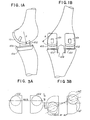
- the Oxford knee is shown in Figures 1A and 1B.
- the femoral components 101 consist of two metal spherical segments, each of constant radius.
- Bearing inserts 102 are circular in shape with a shallow spherical superior surface and a flat inferior surface.
- the tibial onlays 103 consists essentially of two flat plates with fixation by means of a fin 104 at the medial edge of each such flat plate.
- FIG. 5A there is shown a normal knee joint, with the anatomical ramp height designated 105.
- the Oxford prosthesis ramp height 106 is substantially less than the anatomical ramp height105, and therefore the Oxford prosthesis provides less than normal medial-lateral stability.
- medial-lateral shear loads are encountered, additional stress is placed on the cruciate ligaments, which may be already compromised by bone resection.
- such loading in conjunction with flexion or extension, will produce undesirable rubbing between the edges 107 of bearing inserts 102 and the cut edges 108 of the tibial bone.
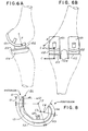
- FIG. 6A-D An alternate embodiment of the Oxford knee which attempts to deal with the problem of dislocation is depicted in Figures 6A-D.
- This design has several deficiencies which make it unworkable, at least with materials now commonly used for such components.
- the anterior-posterior (A-P) travel limit is greatly restricted compared to that of the present invention.
- the present invention is intended to provide an improved prosthesis for the replacement of all or a portion of a dysfunctional human knee joint, particularly to provide a knee prosthesis in which shift of the bearing insert with knee flexion is similar to the normal anatomical shift in the center of the area of contact between femoral and tibial condyles.
- a further object of the present invention is to provide a knee prosthesis which facilitates rotation about one or more axes, even in the presence of perfect congruency and rigidity of the bearing surfaces.
- a further object of the present invention is to provide a knee prosthesis with greater dislocation height, and hence improved dislocation characteristics, than are available with prior-art floating bearing insert type knee prostheses.
- a further object of the present invention is to provide a knee prosthesis with improved medial-lateral stability, substantially unaffected by axial rotation or anterior-posterior (A-P) shift of the bearing insert or inserts.
- a further object of the present invention is to provide a knee prosthesis which substantially reduces the possibility of tipping or dislocation of the bearing insert or inserts.
- a further object of the present invention is to provide a knee prosthesis which allows full flexion of the reconstructed knee.
- a further object of the present invention is to provide a knee prosthesis allowing retention of the cruciate ligaments and capable of both effective,patello-femoral and tibio-femoral articulation.
- a further object of the present invention is to provide a knee prosthesis having reduced tendency toward loosening and collapse, as compared with prior-art floating bearing insert type knee prostheses.
- a further object of the present invention is to provide a knee prosthesis allowing retention of the cruciate ligaments in which contact stresses between the tibial platform and the tibia are minimized.
- a further object of the present invention is to provide a knee prosthesis design which is adaptable to embodiments for unicompartmental, bicompartmental, and tricompartmental knee replacements.
- FIG. 7 - 21 there is shown an endoprosthesis embodying the present invention which has been referred to as tricompartmental knee prosthesis and which includes the femoral component 111 best shown in Figures 7, 8 and 9; the patella prosthesis 112 shwon in Figure 27 and comprising the intermediate patella bearing component 113 best shown in Figures 10, 11, and 12, and the patella fixturing component 114 shown in Figures 13 and 14; and the tibial prosthesis 115 shown in Figure 27 and comprising the tibial platform component 116 best shown in Figures 15, 16, and 17 and the intermediate tibial bearing components 117 shown in Figures 18, 19, 20, and 21.
- the femoral component 111 which includes, in the counter-clockwise anterior to posterior direction, a flange 118 formed integrally with two condyles 119-119.
- the femoral component 111 also includes a pair of fixturing posts; only one fixturing post, post 120, being shown.
- the outside surface of the flange 118 provides most of the bearing surface for patella articulation.
- the condyles 119 are provided for replacing the condylar surfaces of the human femur.
- the bearing surfaces of flange 118 and condyles 119-119 are referred to generally as the bearing surface 121.
- bearing surface 121 in the counter-clockwise anterior to posterior direction is a smooth, continuous surface formed by a series of segments of surfaces of revolution the respective shapes of which are generated or defined by rotating a common generating curve (generally identified as F) around a plurality of generating axes at respective pairs of major generating radii (or each at a respective major generating radius where the radii of each pair are equal) and through respective angles or rotation.
- F common generating curve
- This common generating curve F is a smooth continuous plane curve and as may be understood from Figure 7 the shape of which is defined by (i) two arcs K1 and K2 struck, respectively, by two radii A1 and A2 from respective centers H1 and H2 separated by a distance X; (ii) two tangent lines 123 and 124 respectively tangent to the arcs K1 and K2 and at angles ⁇ 1 and ⁇ 2, respectively, with respect to a line G tangent to arcs K1 and K2; and (iii) an arc K3 struck by radius B from center H3 and wherein arc K3 is also tangent to the tangent lines 123 and 124.
- the shape of the bearing surface 121 ( Figure 7) is defined or generated by a series of segments of surfaces of revolution each of which segments is defined or generated by rotating the common generating curve F around a respective generating axis at respective pairs of major generating radii (or each at a major generating radius where the radii of each pair of major generating radii are equal) and through a respective angle of rotation.
- the common generating curve F is oriented with respect to a generating axis by a pair of major generating radii D1 and D2 which are the respective distances (shortest distances) from points M1 and M2 where the common generating curve F contacts tangent line G as shown in Figure 23.
- FIG 22 is a diagrammatic illustration showing the manner in which the series of segments of surfaces of revolution S1, S2, S3 and S4 defining the shape of the bearing surface 121 are generated and where the curve Q represents the trace of points M1 and M2 as viewed along line G ( Figure 23) resulting from the rotations about the respective generating axes generating the surface segments.
- the shape of the bearing surface 121 is defined by a series of segments of surfaces of revolution where each pair of major generating radii D1 and D2 for generating each segment decrease-in length respectively as rotation of the generating curve F proceeds about each generating axis in the counter-clockwise anterior to posterior direction as viewed in Figure 22.
- the pairs of major generating radii D1 and D2 are equal in each instance and may in each instance be replaced by a single major generating radius R (i.e. R1, R2, R 3 and R4) as shown in Figure 22.
- the bearing surface 121 consists of four segments of surfaces of revolution S1, S2, S3 and S4.
- S1 is generated by rotating the common generating curve F through an angle 91 about generating axis C1 perpendicular to the plane of Figure 22 at a major generating radius R1.
- R1 is equal to infinity and since only the intermediate patella bearing component 113 of figures 10, 11,and 12 articulates with segment S1, it will be referred to as the patello-femoral bearing surface segment.
- Segment S2 is generated by rotating the common generating curve F through an angle ⁇ 2 about generating axis C2 parallel to C1 at a major generating radius R2 where R2 is equal to radius A1 which is equal to A2 in Figure 7; since such radii are equal, it will be understood that segment S2 has two spherical surfaces.
- segment (S2) is of special importance since both the intermediate patella bearing component 113 and the intermediate tibial bearing component 117 articulate with this segment and since the greatest loads on these components during normal walking occur when they articulate against this femoral bearing segment. This segment (S2) will, therefore, be referred to as the primary load bearing surface segment.
- Segment S3 is generated by rotating the common generating curve F through an angle 93 about generating axis C3 parallel to C2 located at major generating radius R3 where R3 is less than R2. Again, for continuity and smoothness of bearing surface 121, axis C3 must lie on ray L2 passing through C2 and defining the end of segment S2.
- segment S4 is generated by rotating the common generating curve F through an angle 94 about generating axis C4 parallel to C2 located at major generating radius R4 which is less than R3. Again for continuity and smoothness of bearing surface 121, axis C4 must lay on ray L3 passing through C3 and defining the end of segment S3. These latter two segments will be referred to, respectively as the first and second posterior femoral bearing surface segments.
- Figure 8 is a sectional view of an actual embodiment of the present invention as shown in Figure 7 and that the segments of surface of revolution S1, S2, S3 and S4 shown in Figure 22 are also shown in Figure 8 at their respective locations.
- the respective angles 9 and each respective major generating radius are as follows:
- the generating axes C1, C2, C3 and C4 are parallel with respect to each other and it will be understood that the tanget line G is oriented substantially parallel to the generating axes.
- the generating axes may be oriented other than parallel with respect to each other and, as shown in the general case illustrated in Figure 23, the tangent line G may be oriented other than parallel to the generating axes.
- such intermediate patella bearing component 113 provides a load-bearing surface indicated by general numerical designation 125 for engaging the bearing surface 121 of femoral component 111 and which load bearing surface 125 includes a primary load bearing surface segment 126, a pair of secondary load bearing surface segments 127 and 128 and a pair of transition segments 129 and 130 between 126 and 127 and 126 and 128 respectively.
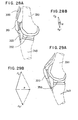
- the shape of the load bearing surface 125 of the intermediate patella bearing component 113 is defined or generated by the common generating curve F used to generate the segments S1-S4 of the bearing surface 121 of femoral component 111.
- the common generating curve F is rotated through an angle e5 (in one embodiment angle 95 equals 20°) about generating axis C5 at the pair of major generating radii D1 and D2 shown in Figure 23, where D1 and D2 are each equal to major generating radius R2 shown in Figure 22, to define the shape of the primary load bearing surface segment 126.
- the patella primary load bearing surface segment 126 congruently matches the primary load bearing surface segment S2 of femoral bearing surface .121 and, upon articulating therewith, engages the primary femoral bearing surface segment S2 in sliding area contact.
- the secondary load bearing surface segments 127 and 128 of the patella load-bearing surface 125 of Figure 11 likewise match the patella femoral bearing surface segment S1 of bearing surface 121 (in Figur 8) and hence their shapes are defined or generated by rotating the common generating curve F about an axis C6 at infinity (and parallel to axis C5) as was done in generating the shape of segment S1 of femoral bearing surface 121.
- the patella prosthesis secondary load-bearing surface segments 127 and 128 congruently match the patello-femoral bearing surface segment S1 of femoral bearing surface 121 and, upon articulating therewith, engage the femoral bearing surface segment S1 in sliding area contact.
- transition segments 129 and 130 are defined by rotating the common generating curve F through an angle e6 about axes C7 and C8 respectively at a pair of negative generating radii (directed to opposite sides of common generating curve F from those shown in Figure 23), both about 0,76 cm (0.30 in.) in one embodiment.
- These transition segments 129 or 130 engage, in line contact, segments S2 and S1 of femoral bearing surface 121 near their interface as the contacts shift from segment S2 of the femoral bearing surface 121 with the primary load bearing segment 126 to contact between femoral segment S1 and the secondary loading bearing segments 127 and 128.
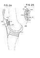
- secondary load bearing surfaces 127 and 128 are inclined downwardly with respect to the horizontal (as viewed in Figure 11) to better accommodate the orientation of the patella prosthesis 112 with respect to the femoral component 111 during full extension of the human knee as shown in Figure 24 and therefore to provide a more uniform load distribution on the secondary load bearing surface segment 127 or 128.
- Patella fixturing component 114 may be suitably affixed to the remnant human patella, using an acrylic grouting agent or cement, by crossed fixturing fins 131 and 132 on the dorsal side of the metal plate 133.
- fixturing fins resist tipping loads, as shown in Figure 25, in which the end that tends to lift is designated reference numeral 210 and the end that is depressed is designated reference numeral 220, and, in addition, provide a reinforcing effect which allows the use of a thin metal plate 133, which is desirable, since one wishes to minimize the change in overall patella thickness resulting from prosthetic replacement so as not to adversely affect patella function, skin closure after surgery and cosmesis.
- the fixturing fins 131, 132 and metal plate 133 reinforce and strengthen the patella remnant and minimize the possibility of its fracture.
- buttons 13 and 26 which comprise the bulk of the secondary fixturing component bearing surfaces which mates with the secondary bearing surface 134 on the intermediate patella bearing component 113, is provided with a button 135 which retains intermediate patella bearing component 113 on the patella fixturing component 114 with a snap fit.
- the outer diameter of the button 135 is formed from a curve with two tangent radii which produce a smooth retaining male surface 136 when mated with corresponding shaped female surface 137 (Figur 10) provided on the intermediate patella bearing component 113. These shapes allow easy entry of the male into the female component without producing the permanent deformation characteristics of conventional snap-fit configurations.
- the mating conical sections provide additional secondary compressive and thrust bearing surfaces.
- the button 135 is provided with a generally conical shaped bearing surface 138 for rotatably engaging the corresponding shaped conical secondary bearing surface 134 (Figure 10) provided on the intermediate patella bearing element 113 in congruent or area rotational engagement to permit rotation of the patella with respect to femoral bearing surface 121 and the distal end of the femur about axis A8 (Figur 27).
- the patella fixturing component 114 is provided with a pin 139 for engaging a corresponding, curved slot 140 formed in the intermediate patella bearing component 113 (Figur 10) to limit the relative rotation between intermediate patella bearing component 113 and the patella fixturing component 114 and thereby prevent disorientation between the intermediate patella bearing component 113 and the femoral component 111 during implantation and subsequently during actual use. Furthermore, this limited rotation has been found to be reasonably necessary since effusion (build up of blood) post-operatively may temporarily lift the load-bearing surface 125 of the intermediate patella bearing component 113 free of the restraining effects of the femoral component 111.
- the intermediate patella bearing component 113 and patella fixturing component 114 are made symmetrical about a plane passing through the center of the primary load bearing surface 126 through the generating axis C5 producing primary load-bearing surface segment 126, so as to allow the use of the same patella prosthesis in either the right or the left knee. It is for this reason that two secondary load bearing segments (127 and 128) are provided on the load bearing surface 125.
- FIG. 28A, 28B, 29A, 29B, 30A, and 30B there is illustrated diagrammatically the manner in which the patello-femoral portion of the tricompartmental prosthesis provides area or congruent sliding contact between the bearing surface 121 of the femoral component 111 and the load bearing surface 125 of the intermediate patella bearing component 113 over the important phase of the range of motion commonly experienced by the human knee, providing line contact between such bearing surfaces only during a brief transitional phase.
- the quadriceps muscle group is designated reference numeral 300, the patella reference numeral 310, the patella tendon reference numeral 320, the femur reference numeral 330, the tibia reference numeral 340 and the area in which the tibio femoral heavy compression force occurs during walking reference numeral 350, it will be noted, that at full knee extension the quadriceps muscle group 300 provides a quadriceps force F Q which in normal activities is quite low at full extension.
- transition segments 129 or 130 of the patella load-bearing surface 125 are in sliding line contact with the femoral bearing surface 121.
- transition segments 129 or 130 of the patella load-bearing surface 125 are in sliding line contact with the femoral bearing surface 121.
- there is no substantial quadriceps activity or force present until approximately 10° of knee flexion is achieved at which the patella articulation of the prosthesis of the present invention has just entered the primary load bearing surface segment S2 wherein there is sliding area contact between the femoral bearing surface segment S2 and the patella primary load bearing segment 126.
- the femoral anterior articular cartilege 360 against which the human patella articulates is in the human knee distinct from that which articulates with the tibia.
- Such natural structures adapt during development of the human knee to produce precise mating of the structural and articulation elements of the knee but such precision of mating is not practical in replacement knee prostheses because of the large individual variations found in different human knees, as well as the manufacturing and surgical difficulties involved in reproducing such precision.
- this component provides a primary load bearing surface 141 on its superior side and a second bearing surface 142 on its inferior side.
- the primary load bearing surface 141 is also formed as a surface of revolution and its shape is defined or generated by the common generating curve the same as or very similar to curve F used to generate the shape of segments S1 - S4 of femoral bearing surface 121 and the shape of patella bearing surface 125.
- the shape of the primary load bearing surface 141 is defined by rotating the common generating curve substantially similar to curve F through an angle e6 (in one embodiment of the present invention e6 equals 60 degrees) about generating axis C6 at the same major generating radii D1 and D2 shown in Figure 23 where D1 and D2 are again each equal to R2 shown in Figure 22.
- e6 in one embodiment of the present invention e6 equals 60 degrees
- the tibial primary load bearing surface 141 is in substantial area contact with the primary load bearing surface segment S2 of femoral bearing surface 121 and, upon articulating therewith, engages the femoral primary bearing surface segment S2 in sliding area contact. Therefore, substantially congruent articulation is provided at the tibio-femoral joint interface for approximately 36 degrees of knee flexion wherein the greatest loads during the walking cycle are experienced as indicated in Figures 29A and 29B.
- load bearing segment S2 The geometry and particularly the shape of load bearing segment S2 are configured so that, in addition to producing the favourable patello-femoral and tibio-femoral articulation described, the intermediate tibial bearing components 117 are held in a forward position on the tibial platform 116, as shown in Figures 32A and 32B. As the knee is flexed slightly the femur, and thus the intermediate tibial bearing components 117, move rearward relative to the tibia so they then occupy a generally central position on the tibial platform 116, as shown in Figure 33A.
- the O to 90 degree flexion-extension range includes almost all strenuous activities in which an indvi- dual with an endoprosthesis is likely to engage.
- the second bearing surface 142 is on the inferior side of the intermediate tibial bearing component 117.
- This bearing surface is composed of a flat surface 143 and a projecting dovetail surface 144.
- the flat and dovetail bearing surface engage the superior surface 145 of the tibial platform component 116 shown in , Figures 15, 16, 17, and 34, and the track surfaces 146 and 154 therein in area contact.
- This tibial platform 116 as shown in Figures 15, 16, and 17, consists of a thick plate 147 with a notched area into which fits the section of the proximal tibia to which the- cruciate ligaments are attached.
- Two curved tracks 148 and 153 are provided in thick plate 147. These curved tracks 148 and 153 receive and partially constrain the two indentical intermediate tibial bearing components 117, which can be seen in Figures 32A and 32B.
- These bearing inserts are substantially identical to the intermediate tibial bearing component illustrated in Figures 18 through 21.
- tick plate 147 of the tibial platform component 116 is contoured so as to engage, where practical, the outer cortical bone of the tibia so as to improve load bearing and to allow this component to be used for both right and left tibias.
- Three short spikes 149, 149, and 172 help distribute joint loads, supply additional load transfer to the cancellous bone, and provide resistance against possible tensile loading.
- intermediate tibial bearing component 117 and tibial platform component 116 eliminates the need to designate a right or left knee aspect, and thus eliminates the concern of the implanting surgeon with these matters during implantation.
- a total movement of ⁇ 6 mm produces a separation change of 0,5 mm.
- This change of separation is easily accommodated by using a very slightly incongruent surface and/or by providing a slight clearance between the walls 150 and 151 ( Figure 34) of curved tracks 148, and the mating projecting dovetail surfaces 144 of the intermediate tibial bearing component 117, shown in Figure 19.
- the contact congruency ratio C when contact is made with segment S2 of the femoral prosthesis, used in one embodiment is approximately 0,99, where C is defined as follows:
- the contact stress is thus kept quite low while still allowing the needed change in separation.
- This line on which lies the center 152 of curvature of the left curved track 153, passes through the center 155 (refer to Figure 7) of the right spherical radius of the primary load bearing segment S2 of femoral component 111 when the components are all assembled.
- the motion could be accommodated (even with perfect congruency and rigidity of the plastic) by virtue of the spherical contact on the right side and the track curvature on the left.
- motion about a normal on the left side could also be accommodated.
- Axial motion about any other normal axis expected in the knee produces slight inward motion of the intermediate tibial bearing components 117 as shown in Figure 36.
- the method of track engagement utilized in the present invention has several functions:
- the New Jersey Meniscal Insert Knee Replacement sacrifies a small amount of congruency (and simplicity) to achieve greatly improved stability.
- the advantages and differences of the NJMIK compared to the prior-art Oxford knee design can be summarized as follows:
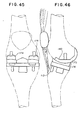
- tibial platform 167 of Figures 40A and 40B for example, tipping loads are resisted by reactive compressive loads on the spike 168.
- Spike 168 also helps support the direct compressive loads as well, as can be seen from Figures 41A and 41B.
- posterior load 164 and lateral load 165 are shown similarly to Figures 39A and 39B.
- the combined effects result in relatively low contact stresses on the bond, in the case of the tibial platform 167 according to the present invention.
- the tibial platform component 116 resists tipping forces by means. of a bridge 169, which can be seen in Figure 16.
- Bridge 169 connects the two tibial plateau sections 170 and 171, and transfers some of the load from one plateau section to the other, as can be seen from Figure 42A.
- Shown for comparison in Figure 42B is a prior-art prosthesis with a flexible platform, which is ineffective in producing any load-sharing across the prosthesis-bone interface.
- the short anterior spike 172 of the present invention shown in Figures 15 and 17, serves to resist posterior loads.
- bridge 169 inhibits the outward splaying fracture of the tibial condyles depicted in Figure 39B.
- FIG. 43 - 46 there is shown a bicompartmental embodiment of the present invention which utilizes a pair of individual femoral components 174 and 175 and, as illustrated diagrammatically in Figures 45 and 46, omits the use of the patella prosthesis 112.
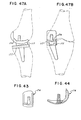
- FIGs 43 and 44 there is shown a right individual femoral component 174 and it will be understood that the individual femoral component 175 shown in Figures 45 and 46 is the mirror image of the right femoral component 174 shown in Figures 43 and 44.
- Tibial prosthesis 115 of this embodiment is the same as the tibial prosthesis 115 already described. It will be understood, and referring to Figure 46, that the individual femoral components, e.g.
- tibial platform 177 As shown in Figures 47A and 47B, is used together with an intermediate tibial bearing component 117, as shown in Figures 18 - 21.
- Figures 47A and 47B show the assembly of tibial platform 177 and intermediate tibial bearing component 117 to form a unicompartmental knee replacement.
- intermediate tibial bearing component 117 may be easily removed intraoperatively to allow replacement of this component with an intermediate tibial bearing component having a thickness providing proper ligamentous (collateral ligaments) tension.
- intermediate tibial bearing components of varying thicknesses may be provided so that the implanting surgeon may shim for proper ligamentous tension or for valgus angle without disturbing fixtured components, e.g. tibial platform component 116 and femoral component 111. Further, such structure allows easy replacement of the intermediate tibial bearing component 117 in the event of unusual or unexpected wear or deformation. Similarly, this is true with respect to the patella prosthesis 112 wherein the intermediate patella bearing component 113 may be of varying thicknesses and replaceable in the event of unusual or unexpected wear or deformation.
- the femoral component 111, the patella fixturing component 11-4, and the tibial platform component 116 may be made preferably of a surgical metal such as cobalt-chromium alloy or titanium or stainless steel but may be made of any relatively rigid material (compared with the grouting agent) that is biocompatible, capable of withstanding the applied loads, and possesses adequate bearing properties against the intermediate bearing inserts, e.g. the intermediate patella bearing component 113 and inter- a mediate tibial bearing component 117 may be made of any biocompatible material strong enough to withstand loads and adequate in bearing against the material with which it is engaged.
- these components are made of a plastic, such as ultra-high molecular weight polyethylene or copolymer acetal.
- FIG. 48 A prosthetic ankle, an alternate embodiment of the present invention, is shown in Figures 48, 49, and 50.
- Talar platform component 178 is implanted in the talus, and tibial component 179 is implanted in the distal tibia.
- Intermediate bearing component 180 is interposed between talar platform component 178 and tibial component 179.
- Talar platform component 178 has a superior bearing surface 181, seen in Figure 48, which consists of a segment of a surface of revolution produced by a generating curve, as can be seen in Figures 48 and 50.
- the generating curve in this case, may typically consist of two 1,588 cm (0,625 in.) radius circular arcs connected by two 20° tangent lines to a 0,635 cm (0,250 in.) radius circular arc. This arrangement is similar in form to the generating curve used for the knee embodiment previously described.
- the inferior portion of talar platform component 178 includes a fixation fin 182, seen in Figure 48, with serrated sides for implantation into the talus.
- Tibial component 179 consists of a flat plate 183 with serrated top edge 184 and a fixation fin 185, both of which are used for implantation into the tibia.
- the plastic intermediate bearing component 180 has an inferior bearing surface 186 complementary to the superior bearing surface 181 of talar platform component 178.
- Intermediate bearing component 180 is also provided with a flat superior bearing surface 187 which matches flat inferior bearing surface 188 of tibial component 179.
- the ankle prosthesis illustrated in Figures 48 - 50 provides flexion-extension motion by rotation of the talar platform component 178 relative to the intermediate bearing component 180.
- Sliding engagement of the flat superior bearing surface 187 of intermediate-bearing component 180 with the flat inferior bearing surface 188 of tibial component 179 allows anterior-posterior translation as well as limited medial-lateral translation.
- the medial-lateral translation is constrained by anatomical features, namely the maleali of the ankle.
- the prosthesis of Figures 48 - 50 includes no mechanical constraints against anterior-posterior or medial-lateral translation, a desirable feature because it minimizes force loads on the components of the prosthesis.
- the prosthetic joint of Figures 48 - 50 also allows axial rotation, that is, rotation about the axis of the femur, without any restraint other than that provided by natural tissues. In addition, it provides unrestrained flexion-extension.
- the purpose of the track i.e. the characteristic shape of the generating curve used for the superior bearing surface 191 of talar platform component 178) is to retain the intermediate bearing component so as to prevent its moving outside the medial-lateral borders of talar platform component 178. In this way intermediate bearing component 180 is prevented from impinging upon adjacent bone.
- the prosthetic joint of Figures 48 - 50 differs from one-half of the prior-art-Oxford knee by virtue of the track-type of contact between talar platform component 178 and intermediate bearing component 180, and also because it affords flexion-extension motion without the possibility of eversion-inversion, at least so long as the joint is under compressive force loads (the normal situation).
- Axial rotation only is provided by the sliding engagement of the flat superior bearing surface 187 of intermediate bearing component 180 with the flat inferior bearing surface 188 of tibial component 179.
- the prior-art Oxford knee incorporates a spherical bearing arrangement allowing three degrees of freedom of rotational motion, rather than two, as provided by the ankle prosthesis according to the present invention.
- FIG. 51 and 52 An implanted prosthetic ankle is shown in Figures 51 and 52. Visible in Figures 51 and 52 are talar platform component 178, intermediate bearing component 180, and tibial component 179. The malealis is designated reference numeral 510. For comparison, an anatomical ankle is illustrated in Figures 53 and 54, in which ligaments are designated reference numeral 520 and the articulating surfaces with 530.
- the track of the present invention which serves to constrain motion of a bearing insert
- there is the track with retention shown in cross-section in Figure 34
- Figure 55 illustrates, in cross-section, still another type of track, suitable for applications where force loads applied to the prosthetic joint are such as to insure retention of bearing insert 189 against shoulder 190 of platform component 191.
- the knee is fully extended and a gently curved S-shaped incision is made on the tibial tubercle up towards the medial border of the patella tendon, then curving posteriorly along the medial border of the vastus medialis.
- the medial retinaculum, capsule and synovial layer are incised in line with the skin incision.
- the vastus medialis muscle belly is elevated free from its attachement to the adductor magnus tendon.
- the patella is reflected laterally exposing the entire tibio-femoral joint. If there is excessive tension in the quadriceps mechanism preventing the complete lateral displacement of the patella, then sharp detachment of the medial 1/4 of the patella tendon from the tibial tubercle may be necessary. In a similar fashion, further blunt disection of the medial attachment of the vastus medialis may be needed to mobilize the quadriceps mechanism proximally. These maneuvers will allow complete flexion of the knee to 110 degrees with complete anterior exposure of the joint.
- bone guards are slid posteriorly between the collateral ligaments and the posterior capsule to protect the posterior neurovascular bundle during resection of the articular surface.
- a 3/4" (2 cm) periosteal elevator may be used to develop the soft tissue planes for the bone guards, which also serve as knee retractors.
- the knee is flexed to 100 degrees and a drill hole at the intercondyler notch border is made with a 1/4" (0,6 cm) drill.
- the drill is taken down to the level of the posterior femoral shaft.
- a tibial resection jig is placed with a spike located on the posterior aspect of the femoral shaft and a distal limb of the instrument parallel to the tibia.
- the jig has an automatic 10 degree retro- version angle insured when the knee is flexed parallel to the distal limb of the jig.
- the tibial preparation is made leaving a ridge of bone to which the cruciate ligaments insert.
- the resection planes are made at 5, 10, or 15 mm, depending upon the amount of bone stock available for perpendicular loading of the tibial component.
- the knee is then brought into full extension after removal of the femoral shaper and an extension femoral alignment jig is placed into the joint.
- an extension femoral alignment jig is placed into the joint.
- the horizontal cut of the distal femur is made to insure adequate extension tension of the collateral ligaments.
- the extension alignment jig is removed from the knee joint.
- the knee is again flexed and an oblique osteotomy jig is replaced into the fixturing hole and using a mallet impacted into the distal femoral bone stock.
- the anterior and posterior oblique cuts are then made in line with the jig surface and a central notch of the oblique osteotomy jig is used to trim away the boney surface for the anterior femoral flange.
- the oblique osteotomy jig is removed and the alignment holes made by the jig are curetted out to accept the fixturing pins of the femoral prosthesis.
- a trial fit of the femoral component is next made. Excessive bone stock is trimmed to insure proper contact of all surfaces.
- the tibial preparation is completed.
- a marking template is used to mark out the tibial component spike positions.
- tibial component spike channels are fashioned using a curette or gouge.
- a trial seating of the tibial component is next made and proper bone resection is performed at this time to insure excellent metal to bone contact of the prosthesis.
- the trial reduction of the tibial and femoral components is made as follows:
- the metal tibial component is placed on the proximal tibia and the appropriate intermediate bearing components are inserted into place.
- the femoral component is placed in its proper position and the knee joint is tested in both flexion and extension for proper ligamentous tension. If resection cuts have been made properly, there should be no gross instability. Should mild laxity exist in flexion and extension, then thicker intermediate tibial bearing components may be used to tighten the collateral ligaments.
- the bearing heights come in 2.5 mm increments and may be used to finely adjust the ligamentous tension at this stage. These may also be used to correct varus- valus alignment.
- the synovial tissue and retinaculum are freed from the periphery of the patella down to the level of the patella tendon.
- a reciprocating saw is then used to remove the articular surface. The plane of the cut should parallel the inferior surface of the patella tendon.
- a patella marking template is now centered over the horizontal and vertical axis of the patella with the long fixturing fin directed toward the lateral aspect.
- Methylene blue dye is used to mark the fin channels for the fixturing fins of the component. These channels are taken to a depth of 1/4" (0,6 cm) and undercut for mechanical locking of the cement.
- the trial patella replacement can now be seated to assess the fit. Any boney impingement is removed to insure proper seating. The patella is reflected to its anatomical position to check the alignment in the femoral track. A range of motion may now be tested with all three components in place. The patella prosthesis should center in the femoral track and easily glide along the femoral flange without binding. Restricting adhesions or boney impingement should be completely corrected at this time.
- the components are removed after a satisfactory trial fit and the wound is thoroughly irrigated with antibiotic saline solution.
- the first batch of methylmethacrylate is mixed and placed on the tibial surface with the kee in the flexed position.
- the tibial component is gently slid into its fixturing channels and firmly held in compression until complete polymerization has been obtained.
- excess methylmethacrylate may be trimmed using a scalpel and curette from the edges of the tibial component.
- the bearing components are placed into the tibial component and the femoral component is cemented in place.
- methylmethacrylate is removed from around the femoral component to insure that the bearing surface will remain free of this abrasive agent.
- the cancellous patella bed is covered.
- the patellar component fixturing fins are firmly pressed into their mating channels and the component is held tightly with a patellar component clamp.
- Excess methylmethacrylate may now be removed from the edges of the patella backplate. Upon complete polymerization of all cement beds, a range of motion is again tested after returning the patella to its anatomical position.
- Two medium sized hemovac drains are now placed in the joint space and brought to exit laterally above the incision line.
- a single layer closure of capsule and retinaculum is performed with #2-0 chromic suture with the knee flexed 30 degrees for the first several sutures, then to 60 degrees with the second set of sutures, and finally, to 90 degrees for the remaining closure sutures.
- Subcutaneous tissue is closed with #3-0 plain suture, skin in re-approximated in a tension-free fashion with #3-0 nylon suture.
- Hemovac drains are hooked to suction and a Robert-Jones compression dressing is applied. The leg is elevated and the patient is taken to the recovery room where ice packs are placed about the knee.
Abstract
Description
- This invention relates to a prosthetic joint, particularly to a prosthesis for replacement of.a dysfunctional knee joint.
- Referring now to prior art knee endoprostheses, and in particular to the prior art knee prostheses with patello-femoral replacement, it has been observed that such prior art prostheses have poorly designed patello-femoral interfaces in that they do not provide reasonablecongruentpatello-femoral contact or sliding engagement over any appreciable range of knee motion.
- More particularly, such prior art prostheses typically produce contact stresses which result in yielding and fatigue of the plastic bearing surface typically present in such prostheses. This result is caused by the fact that the bearing surface of the femoral component, over which the patella prosthesis must pass, generally has several regions or segments of differing shape. For example, there is typically a fairly long, singly curved segment blending into a first doubly curved segment blending'again into a second, and different, doubly curved segment. These varying segments or regions provide the femoral portion of the femoral-tibial articulation, and those segments or regions do not have a common generating curve. Thus, when the patella prosthesis goes through its excursion over the femoral articular flange, the patella prosthesis undergoes a variety of contact conditions, namely, substantial portions of line contact, portions of point contact, and perhaps limited portions of area or congruent area contact. As is known, line contact and point contact conditions generally produce high contact stresses which produce yielding and substantial wear of plastic prostheses. Hence, the extended wear life needed for sucessful prosthetic implantation is not realized.
- Referring next to typical prior art tibio-femoral knee prostheses, it has been observed that those prior art knee prostheses which allow axial rotation and anterior-posterior motion in addition to flexion-extension motion have an incongruent contact (usually theoretical point-contact) between the femoral and tibial bearing surfaces, producing excessive contact stresses leading to deformation and/or early wear and undesirably short prosthetic life. Also, wear products have been shown to produce undesirable tissue reactions which may contribute to loosening of the prosthetic components.
- Those prior art kee prostheses which do provide congruent or area bearing contact fail to provide the needed axial rotation, or when cruciates are present the needed anterior-posterior motion. This lack of axial rotation and anterior-posterior motion has been shown clinically and experimentally to result in deformation and loosening of the tibial components, and such prostheses now appear to be falling into disuse.
- Current prostheses of the dislocatable cruciate retaining type, such as the Geomedic knee replacement shown in U.S. Patent No. 3.728.742, that produce area contact provide only one axis of rotation relative to the femur for the flexion-extension motion. Normal flexion-extension is, however, characterized by a polycentric flexion-extension motion where rotation relative to the femur occurs about many axes. This polycentric motion, which results from the action of the cruciate ligaments and condylar shape, allows for more efficient utilization of muscle forces by providing a posterior shift of the axis when effective quadriceps action is important and an anterior shift when hamstrings effectiveness is important. Furthermore, in the human knee it is this polycentric action, and the shape of the posterior condyles, which influence this motion so as to allow full flexion capability for the knee. Failure to provide appropriate knee geometry inhibits, when cruciate ligaments are present, this natural polycentric motion and thus tends to restrict muscle effectiveness and inhibit flexion. These restrictions tend to increase both loading on the prosthesis (which increases wear or likelihood of deformation or breakage) and loading between prosthesis and bone (which increases the possibility of component loosening).
- Other knee designs, such as the Townley type, avoid overconstraint by introducing incongruency of the articulating surfaces. The incongruency, while necessary to avoid overconstraint, unfortunately results in instability and excessive contact stresses.
- It is further believed that loosening problems result from the direct attachment of plastic prosthetic components to bone through the use of relatively brittle cement that is weak in tension. Specifically, it has been demonstrated that even relatively thick plastic components when loaded in a normal fashion produce undesirable tensile stresses in the acrylic cement commonly used to secure such plastic components to bone. Such loading tends to produce bending of the plastic component which causes the ends of the plastic component to lift away from the bone, thereby subjecting the bone-cement attachment to tension. As is known, cement has very poor tensile fatigue properties. The bone to which the plastic prosthesis is cemented also appears to be adversely affected by tensile loads. Accordingly, it is believed that these combined effects contribute substantially to prosthetic loosening problems and, specifically, it has been noted where clinical failure due to loosening occurs in a knee prosthesis that it is almost always the plastic prosthesis component which loosens.
- Another prior art prosthesis problem exists with regard to knee endoprostheses for implantation in those cases wherein the cruciate ligaments are functionally absent but where the collaterial ligaments are functional or at least reconstructable. In the absence of cruciate ligaments, the prosthetic replacement must provide anterior-posterior knee joint stability so as to replace that stability otherwise provided by the cruciates. Until recently most such cases were treated by a stable hinge-type knee prosthesis which, unfortunately, appears to suffer from the loosening problems described above and furthermore typically produces substantial bone loss as a result of the relatively great bone resection required for implantation. Necrosis of the bone, caused by altered mechanical bone stresses, is also a problem with the hinge-type knee prostheses. More recent attempts have been made to treat such cases -with surface replacement prostheses such as the prostheses known as the Total Condylar and similar knee prostheses. However, these knee prostheses have theoretical point-contact bearing surfaces with their above-noted attendant problems and, in addition, such prostheses tend to have instability and dislocation problems which result, at least in part, from these point-contact bearing surfaces.
- Where the cruciate ligaments are present, most surgeons would prefer their retention, since they provide important internal stablizers and, together with the condylar geometry of the femur and tibia, control the rotation axis of the knee. Furthermore, these ligaments provide anterior-posterior (A-P) stability. Thus, it is desirable to preserve the cruciate ligaments, even though reasonable stability can be provided by a properly designed full platform type prosthesis.
- In addition, the action of the cruciate ligaments produces a shift in the rotation axis of the knee which may result in more efficient muscle utilization. Thus, preservation of these structures may provide better physiological function after knee replacement.
- Still, it is not clear that the physiological advantages gained in retaining the cruciates outweigh the disadvantages of the design compromises, such as increased bearing surface incongruency and reduced tibial prosthesis bearing area, required to retain these ligaments. Thus, the desirability of retaining the cruciate ligaments in the cases of bicompartmental and tricompartmental replacement is not well established. The design described herein, however, eliminates or compensates for these design compromises, thus allowing the benefits of cruciate retention with minimal or not apparent loss in the ability of the prosthesis to withstand the loads to which it is subjected.
- In unicompartmental replacement, the cruciates must be retained in any event since there is insufficient stability in their absence with a unicondylar replacement. Thus, for such cases a design which accommodates the cruciate ligaments is necessary.
- Unicompartmental replacement with a proper bearing design allows surgical restoration of a single diseased compartment, rather than the sacrifice or normal structures to replace all three compartments of the knee. Further, reducing the number of compartments replaced has the effect of reducing prosthesis wear products. Recent evidence strongly suggests that these wear products produce adverse physiological response to the prosthesis, including an increased tendency for the prosthesis to loosen from its boney attachment.
- A recent experimental knee concept, the Oxford knee, appears to provide a partial solution to the problem of overconstraint while maintaining congruency by the use of meniscal floating elements. Unfortunately, this knee suffers from several design problems which appear to limit its usefulness. The present invention, the New Jersey Meniscal Bearing Knee Replacement (NJMBK) utilizes similar concepts in an improved fashion in order to avoid some of the anticipated difficulties of the Oxford design.
- The Oxford knee is shown in Figures 1A and 1B. The
femoral components 101 consist of two metal spherical segments, each of constant radius.Bearing inserts 102 are circular in shape with a shallow spherical superior surface and a flat inferior surface. Thetibial onlays 103 consists essentially of two flat plates with fixation by means of afin 104 at the medial edge of each such flat plate. - There are several serious problems with the design of the Oxford knee of Figures 1A and 1B, having a single rotation axis. The most basic problem is the potential for dislocation of
bearing inserts 102 resulting from the limited flexion range of the device. As can be seen from Figures 2A and 2B, the design provides excellent congruent contact up to about 90° flexion. Beyond that point a surface of constant radius cannot provide proper contact within the geometric constraints imposed by having to fit the prosthesis to the human knee. Flexion substantially beyond 90° produces edge contact and resulting deformation and possible dislocation ofbearing inserts 102. Although 90° of flexion is satisfactory from a functional standpoint, it is impractical to limit motion to this range, since activities will be encountered (such as sitting onto a low chair, or returning to the standing position after sitting in a low chair) where-flexion substantially exceeds 90°. - The problem of insert dislocation is made more severe by axial rotation of the knee, as is shown in Figures 3A and 3B. In Figure 3A, there is shown the position of
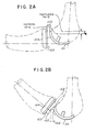
bearing inserts 102 at 90° flexion, but with no axial rotation of the knee. In Figure 3B there is shown the position ofbearing inserts 102 at 90° flexion, but with 15° (solid lines) and 30° (dashed lines) of axial rotation as well. There is a pronounced overhang ofbearing inserts 102, with resultant risk of dislocation, under the combination of 90° flexion and 30° axial rotation of the knee. - Normal distraction of one compartment of the knee during the swing phase of walking, as depicted in Figure 4, also leaves bearing insert 102 of the prior-art Oxford knee free to dislocate.
- A further disadvantage of the Oxfprd knee arises from the shallowness and placement of the arcs of the contact surfaces, as can be seen from Figures 5A and 5B. In Figure 5A there is shown a normal knee joint, with the anatomical ramp height designated 105. Note, in Figure 5B, that the Oxford
prosthesis ramp height 106 is substantially less than the anatomical ramp height105, and therefore the Oxford prosthesis provides less than normal medial-lateral stability. Thus, when medial-lateral shear loads are encountered, additional stress is placed on the cruciate ligaments, which may be already compromised by bone resection. Furthermore, such loading, in conjunction with flexion or extension, will produce undesirable rubbing between theedges 107 of bearinginserts 102 and the cut edges 108 of the tibial bone. - Other weaknesses of the Oxford design include lack of accommodation for patella replacement, and tibial plateau components with relatively poor load-bearing properties, as will be described later.
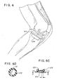
- An alternate embodiment of the Oxford knee which attempts to deal with the problem of dislocation is depicted in Figures 6A-D. Unfortunately, this design has several deficiencies which make it unworkable, at least with materials now commonly used for such components. The anterior-posterior (A-P) travel limit is greatly restricted compared to that of the present invention. There is substantial
unsupported area 109 ofplastic bearing insert 102, as can be seen from the cross-sectional view of Figure 6C. Flexure of theplastic bearing insert 102 will occur, transferring load to the remaining areas and thus greatly increasing bearing compressive stresses. High stress will occur in the inner cavity at the head of retainingpin 110, particularly at the edge of retainingpin 110 and at the contact between the end of retainingpin 110 and the inner cavity, as can be seen from the cross-sectional view of Figure 6D. Furthermore, the use of retainingpin 110 makes installation of the bearing element difficult after implantation of femoral and tibial components, since it is necessary to separate the knee joint by stretching the ligaments an amount equal to the pin height in addition to the separation normally required to install bearing inserts 102. - The present invention is intended to provide an improved prosthesis for the replacement of all or a portion of a dysfunctional human knee joint, particularly to provide a knee prosthesis in which shift of the bearing insert with knee flexion is similar to the normal anatomical shift in the center of the area of contact between femoral and tibial condyles.
- A further object of the present invention is to provide a knee prosthesis which facilitates rotation about one or more axes, even in the presence of perfect congruency and rigidity of the bearing surfaces.
- A further object of the present invention is to provide a knee prosthesis with greater dislocation height, and hence improved dislocation characteristics, than are available with prior-art floating bearing insert type knee prostheses.
- A further object of the present invention is to provide a knee prosthesis with improved medial-lateral stability, substantially unaffected by axial rotation or anterior-posterior (A-P) shift of the bearing insert or inserts.
- A further object of the present invention is to provide a knee prosthesis which substantially reduces the possibility of tipping or dislocation of the bearing insert or inserts.
- A further object of the present invention is to provide a knee prosthesis which allows full flexion of the reconstructed knee.
- A further object of the present invention is to provide a knee prosthesis allowing retention of the cruciate ligaments and capable of both effective,patello-femoral and tibio-femoral articulation.
- A further object of the present invention is to provide a knee prosthesis having reduced tendency toward loosening and collapse, as compared with prior-art floating bearing insert type knee prostheses.
- A further object of the present invention is to provide a knee prosthesis allowing retention of the cruciate ligaments in which contact stresses between the tibial platform and the tibia are minimized.
- A further object of the present invention is to provide a knee prosthesis design which is adaptable to embodiments for unicompartmental, bicompartmental, and tricompartmental knee replacements.
- A complete understanding of the invention may be obtained from the detailed description which follows, together with the accompanying drawings, wherein:
- Figures 1A and 1B are diagrammatic views of the prior-art Oxford knee.
- Figures 2A and 2B illustrate the prior-art Oxford knee at 85° and 120° (respectively), showing at 85° flexion the excess posterior displacement se of the bearing inserts resulting from use of single radius of curvature. Two possible dislocation modes of the bearing inserts are shown at 120° flexion.
- Figure 3A and 3B also depict the prior-art Oxford knee. Figure 3A shows in plan view, the position of the bearing inserts at 90° flexion with no rotation of the knee. Figure 3B shows the positions of the bearing inserts at 90° flexion in the presence of axial rotations of 15° and 30°.
- Figure 4 illustrates the possibility of dislocation of the bearing inserts, in the prior-art Oxford knee, in the swing phase of walking. Figures 5A and 5B compare the anatomical ramp height with the ramp height provided by the prior-art Oxford knee prosthesis. Figures 6A through 6D illustrate some of the disadvantages which result from a design modification to partially constrain the bearing inserts of the prior-art Oxford knee.
- Figures7 through 9 show the femoral component of the present invention, the New Jersey Meniscal Insert Knee.
- Figures 10 through 12 show the intermediate patella bearing component according to the present invention.
- Figures13 and 14 show the patella fixturing component according to the present invention.
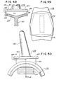
- Figures 15 through 17 show the tibial platform component according to the present invention.
- Figures 18 through 21 show the intermediate tibial bearing component according to the present invention.
- Figure 22 illustrates the manner in which the surface of the femoral component according to the present invention is generated by a series of segments of surfaces of revolution.
- Figure 23 illustrates the manner in which the several bearing surfaces of the present invention are generated by rotating a common generating curve about a particular generating axis at pairs of major generating radii.
- Figure 24 shows the orientation of the patella prosthesis relative to the femoral component at full extension of the knee.
- Figure 25 illustrates the role of the fixturing fins (of the patella fixturing component) is resisting tipping loads.
- Figure 26 shows the button portion of the patella fixturing component, which is used to retain the intermediate patella bearing component.
- Figure 27 shows the manner in which the present invention permits rotation of the patella with respect to the femoral bearing surface.
- Figures 28A and 28B illustrate the relatively low patello-femoral compression force present at full extension of the knee.
- Figures 29A and 29B illustrate the somewhat greater patello-femoral compression force present in the load-bearing stance phase of the normal walking cycle.
- Figures30A and 30B illustrate the much greater patello-femoral compression force present in deep knee flexion.
- Figure 31 is an inferior view of the distal femur, showing the femoral anterior articular cartilege involved in patello-femoral articulation, as well as the femoral posterior articular cartilege involved in tibio-femoral articulation.
- Figures 32A and 32B show the manner in which the intermediate tibial bearing components are held in a forward position, on the tibial platform, by virtue of the shape of the bearing surface of the femoral components
- Figures 33A and 33B show the manner in which the intermediate tibial bearing components move posteriorly with flexion of the knee. Figure 33A shows 15° flexion with the intermediate tibial bearing components in their central position, while Figure 33B shows 120° flexion with the intermediate tibial bearing components in their posterior position.
- Figure 34 is a cross-sectional view of the curved track of the tibial platform component according to the present invention.
- Figures 35A and 35B illustrate the manner in which the intermediate tibial bearing components move slightly closer together as they move forward and rearward from a central position in the curved track of the tibial platform component.
- Figure 36 illustrates the manner in which the intermediate tibial bearing components move slightly closer together as the femur moves posteriorly.
- Figures 37A and 37B show the manner in which the use of an eccentric bearing insert (i.e. the intermediate tibial bearing component) allows a relatively great inward shift of the bearing insert with little incongruency.
- Figures 38A through 38C illustrate several advantages of the intermediate tibial bearing component according to the present invention. The larger platform (relative to that of the circular bearing insert of the prior-art Oxford knee) is shown in Figures 38A. Figure 38B illustrates the greater dislocation height of the present invention, and Figure 38C illustrates the noncentral spherical radius of the present invention.
- Figures 39A and 39B illustrate the undesirable tensile stresses produced in the prosthesis-bone interface by the MacIntosh type tibial onlays of the prior-art Oxford knee.
- Figures 40A and 40B show the tibial platform of a unicompartmental version of the present invention.
- Figures 41A and 41B show the manner in which the spike of the tibial platform of the unicompartmental version of the present invention resists both tipping and compressive loads.
- Figures 42A and 42B compare the tibial platform component of the present invention with a prior-art prosthesis utilizing: a flexible platform, which is ineffective in producing any load-sharing across the prosthesis bone interface.
- Figures 43 and 44 show the femoral component of a unicompartmental version of the present invention.
- Figures 45 and 46 show an implanted bicompartmental version of the present invention, utilizing a pair of individual femoral components.
- Figure 47A and 47B show an implanted unicompartmental version of the present invention.
- Figures 48, 49 and 50 illustrate an ankle prosthesis according to the present invention.
- Figure 48 is a cross-sectional view of the prosthesis, as indicated in Figure 50.
- Figures 51 and 52 show the implanted ankle prosthesis according to the present invention.
- Figures 53 and 54 show an anatomical ankle, for comparison with the implanted ankle prosthesis of Figures 51 and 52.
- Figure 55 shows, in schematic cross-section, . an alternative track (consisting of just a shoulder, rather than a channel) suitable for applications where force loads applied to the prosthetic joint are such as to insure retention of the bearing insert against the shoulder.
- Referring now to Figures 7 - 21, there is shown an endoprosthesis embodying the present invention which has been referred to as tricompartmental knee prosthesis and which includes the
femoral component 111 best shown in Figures 7, 8 and 9; thepatella prosthesis 112 shwon in Figure 27 and comprising the intermediatepatella bearing component 113 best shown in Figures 10, 11, and 12, and thepatella fixturing component 114 shown in Figures 13 and 14; and thetibial prosthesis 115 shown in Figure 27 and comprising thetibial platform component 116 best shown in Figures 15, 16, and 17 and the intermediatetibial bearing components 117 shown in Figures 18, 19, 20, and 21. - Referring- now to Figures 7, 8, and 9, there is shown in detail the
femoral component 111 which includes, in the counter-clockwise anterior to posterior direction, aflange 118 formed integrally with two condyles 119-119. Thefemoral component 111 also includes a pair of fixturing posts; only one fixturing post, post 120, being shown. The outside surface of theflange 118 provides most of the bearing surface for patella articulation. Thecondyles 119 are provided for replacing the condylar surfaces of the human femur. The bearing surfaces offlange 118 and condyles 119-119 are referred to generally as the bearingsurface 121. In accordance with the teaching of the present invention, bearingsurface 121 in the counter-clockwise anterior to posterior direction is a smooth, continuous surface formed by a series of segments of surfaces of revolution the respective shapes of which are generated or defined by rotating a common generating curve (generally identified as F) around a plurality of generating axes at respective pairs of major generating radii (or each at a respective major generating radius where the radii of each pair are equal) and through respective angles or rotation. - This common generating curve F is a smooth continuous plane curve and as may be understood from Figure 7 the shape of which is defined by (i) two arcs K1 and K2 struck, respectively, by two radii A1 and A2 from respective centers H1 and H2 separated by a distance X; (ii) two
tangent lines tangent lines - Referring now to Figure 23, where a further understanding of the general teachings of the present invention is illustrated, it will be understood that the shape of the bearing surface 121 (Figure 7) is defined or generated by a series of segments of surfaces of revolution each of which segments is defined or generated by rotating the common generating curve F around a respective generating axis at respective pairs of major generating radii (or each at a major generating radius where the radii of each pair of major generating radii are equal) and through a respective angle of rotation. In generating each segment of a surface of revolution, the common generating curve F is oriented with respect to a generating axis by a pair of major generating radii D1 and D2 which are the respective distances (shortest distances) from points M1 and M2 where the common generating curve F contacts tangent line G as shown in Figure 23.
- Referring now to figure 22, it will be understood that this figure is a diagrammatic illustration showing the manner in which the series of segments of surfaces of revolution S1, S2, S3 and S4 defining the shape of the bearing
surface 121 are generated and where the curve Q represents the trace of points M1 and M2 as viewed along line G (Figure 23) resulting from the rotations about the respective generating axes generating the surface segments. It will be further understood that the shape of the bearingsurface 121 is defined by a series of segments of surfaces of revolution where each pair of major generating radii D1 and D2 for generating each segment decrease-in length respectively as rotation of the generating curve F proceeds about each generating axis in the counter-clockwise anterior to posterior direction as viewed in Figure 22. In the present embodiment and as illustrated in Figure 23, the pairs of major generating radii D1 and D2 are equal in each instance and may in each instance be replaced by a single major generating radius R (i.e. R1, R2, R3 and R4) as shown in Figure 22. In this embodiment, the bearingsurface 121 consists of four segments of surfaces of revolution S1, S2, S3 and S4. - S1 is generated by rotating the common generating curve F through an angle 91 about generating axis C1 perpendicular to the plane of Figure 22 at a major generating radius R1.Inthe present embodiment, R1 is equal to infinity and since only the intermediate
patella bearing component 113 of figures 10, 11,and 12 articulates with segment S1, it will be referred to as the patello-femoral bearing surface segment. - Segment S2 is generated by rotating the common generating curve F through an angle θ2 about generating axis C2 parallel to C1 at a major generating radius R2 where R2 is equal to radius A1 which is equal to A2 in Figure 7; since such radii are equal, it will be understood that segment S2 has two spherical surfaces.
- For continuity and smoothness of bearing
surface 121, axis C2 must lie on the ray L1 passing through C1 and defining the end of segment S1. This segment (S2) is of special importance since both the intermediatepatella bearing component 113 and the intermediatetibial bearing component 117 articulate with this segment and since the greatest loads on these components during normal walking occur when they articulate against this femoral bearing segment. This segment (S2) will, therefore, be referred to as the primary load bearing surface segment. - Segment S3 is generated by rotating the common generating curve F through an angle 93 about generating axis C3 parallel to C2 located at major generating radius R3 where R3 is less than R2. Again, for continuity and smoothness of bearing
surface 121, axis C3 must lie on ray L2 passing through C2 and defining the end of segment S2. - Finally, segment S4 is generated by rotating the common generating curve F through an angle 94 about generating axis C4 parallel to C2 located at major generating radius R4 which is less than R3. Again for continuity and smoothness of bearing
surface 121, axis C4 must lay on ray L3 passing through C3 and defining the end of segment S3. These latter two segments will be referred to, respectively as the first and second posterior femoral bearing surface segments. - Referring again to Figure 8, it will be understood that Figure 8 is a sectional view of an actual embodiment of the present invention as shown in Figure 7 and that the segments of surface of revolution S1, S2, S3 and S4 shown in Figure 22 are also shown in Figure 8 at their respective locations.
- In one embodiment of the present invention, the respective angles 9 and each respective major generating radius are as follows:

- Referring again to Figures 8 and 22, it will be noted that the generating axes C1, C2, C3 and C4 are parallel with respect to each other and it will be understood that the tanget line G is oriented substantially parallel to the generating axes. However, in accordance with the teachings of the present invention, such need not be the case and the generating axes may be oriented other than parallel with respect to each other and, as shown in the general case illustrated in Figure 23, the tangent line G may be oriented other than parallel to the generating axes.
- Referring again to thepatella prosthesis and in particular to the imtermediate
patella bearing component 113 of Figures 10, 11, and 12, it will be understood that in accordance with the further teachings of the present invention such intermediatepatella bearing component 113 provides a load-bearing surface indicated by generalnumerical designation 125 for engaging the bearingsurface 121 offemoral component 111 and which load bearingsurface 125 includes a primary load bearing surface segment 126, a pair of secondary load bearingsurface segments transition segments 129 and 130 between 126 and 127 and 126 and 128 respectively. Further, it will be under- stood in accordance with the teachings of the present invention that the shape of theload bearing surface 125 of the intermediatepatella bearing component 113 is defined or generated by the common generating curve F used to generate the segments S1-S4 of the bearingsurface 121 offemoral component 111. Referring to Figure 11, it will be understood that the common generating curve F is rotated through an angle e5 (in one embodiment angle 95 equals 20°) about generating axis C5 at the pair of major generating radii D1 and D2 shown in Figure 23, where D1 and D2 are each equal to major generating radius R2 shown in Figure 22, to define the shape of the primary load bearing surface segment 126. Therefore, the patella primary load bearing surface segment 126 congruently matches the primary load bearing surface segment S2 of femoral bearing surface .121 and, upon articulating therewith, engages the primary femoral bearing surface segment S2 in sliding area contact. The secondary load bearingsurface segments bearing surface 125 of Figure 11 likewise match the patella femoral bearing surface segment S1 of bearing surface 121 (in Figur 8) and hence their shapes are defined or generated by rotating the common generating curve F about an axis C6 at infinity (and parallel to axis C5) as was done in generating the shape of segment S1 of femoral bearing surface 121.Therefore, the patella prosthesis secondary load-bearing surface segments femoral bearing surface 121 and, upon articulating therewith, engage the femoral bearing surface segment S1 in sliding area contact. Thetransition segments 129 and 130 are defined by rotating the common generating curve F through an angle e6 about axes C7 and C8 respectively at a pair of negative generating radii (directed to opposite sides of common generating curve F from those shown in Figure 23), both about 0,76 cm (0.30 in.) in one embodiment. Thesetransition segments 129 or 130 engage, in line contact, segments S2 and S1 offemoral bearing surface 121 near their interface as the contacts shift from segment S2 of thefemoral bearing surface 121 with the primary load bearing segment 126 to contact between femoral segment S1 and the secondaryloading bearing segments - In another embodiment of the patella prosthesis of the present invention, secondary
load bearing surfaces patella prosthesis 112 with respect to thefemoral component 111 during full extension of the human knee as shown in Figure 24 and therefore to provide a more uniform load distribution on the secondary load bearingsurface segment - The intermediate patella bearing component-113 is retained on the remnant of the human patella by use of the
patella fixturing component 114 of Figures 13 and 14.Patella fixturing component 114 may be suitably affixed to the remnant human patella, using an acrylic grouting agent or cement, by crossedfixturing fins metal plate 133. Such fixturing fins resist tipping loads, as shown in Figure 25, in which the end that tends to lift is designatedreference numeral 210 and the end that is depressed is designatedreference numeral 220, and, in addition, provide a reinforcing effect which allows the use of athin metal plate 133, which is desirable, since one wishes to minimize the change in overall patella thickness resulting from prosthetic replacement so as not to adversely affect patella function, skin closure after surgery and cosmesis. Thefixturing fins metal plate 133 reinforce and strengthen the patella remnant and minimize the possibility of its fracture. The opposite or ventral side ofmetal plate 133, Figur 13, which comprise the bulk of the secondary fixturing component bearing surfaces which mates with thesecondary bearing surface 134 on the intermediatepatella bearing component 113, is provided with abutton 135 which retains intermediatepatella bearing component 113 on thepatella fixturing component 114 with a snap fit. As shown in figures 13 and 26, the outer diameter of thebutton 135 is formed from a curve with two tangent radii which produce a smooth retainingmale surface 136 when mated with corresponding shaped female surface 137 (Figur 10) provided on the intermediatepatella bearing component 113. These shapes allow easy entry of the male into the female component without producing the permanent deformation characteristics of conventional snap-fit configurations. The mating conical sections provide additional secondary compressive and thrust bearing surfaces. Thebutton 135 is provided with a generally conical shaped bearingsurface 138 for rotatably engaging the corresponding shaped conical secondary bearing surface 134 (Figure 10) provided on the intermediatepatella bearing element 113 in congruent or area rotational engagement to permit rotation of the patella with respect tofemoral bearing surface 121 and the distal end of the femur about axis A8 (Figur 27). - Further, and referring to Figure 13, the
patella fixturing component 114 is provided with apin 139 for engaging a corresponding,curved slot 140 formed in the intermediate patella bearing component 113 (Figur 10) to limit the relative rotation between intermediatepatella bearing component 113 and thepatella fixturing component 114 and thereby prevent disorientation between the intermediatepatella bearing component 113 and thefemoral component 111 during implantation and subsequently during actual use. Furthermore, this limited rotation has been found to be reasonably necessary since effusion (build up of blood) post-operatively may temporarily lift the load-bearing surface 125 of the intermediatepatella bearing component 113 free of the restraining effects of thefemoral component 111. - It will be further noted,as shown in Figure 10 - 14, that the intermediate
patella bearing component 113 andpatella fixturing component 114 are made symmetrical about a plane passing through the center of the primary load bearing surface 126 through the generating axis C5 producing primary load-bearing surface segment 126, so as to allow the use of the same patella prosthesis in either the right or the left knee. It is for this reason that two secondary load bearing segments (127 and 128) are provided on theload bearing surface 125. - Referring now to Figures 28A, 28B, 29A, 29B, 30A, and 30B, there is illustrated diagrammatically the manner in which the patello-femoral portion of the tricompartmental prosthesis provides area or congruent sliding contact between the
bearing surface 121 of thefemoral component 111 and theload bearing surface 125 of the intermediatepatella bearing component 113 over the important phase of the range of motion commonly experienced by the human knee, providing line contact between such bearing surfaces only during a brief transitional phase. Referring first to Figures 28A and 28B, in which the quadriceps muscle group is designatedreference numeral 300, thepatella reference numeral 310, the patellatendon reference numeral 320, thefemur reference numeral 330, thetibia reference numeral 340 and the area in which the tibio femoral heavy compression force occurs during walkingreference numeral 350, it will be noted, that at full knee extension thequadriceps muscle group 300 provides a quadriceps force FQ which in normal activities is quite low at full extension. - Because of the orientation of the force FQ the resultant patello-femoral compression force R of Figure 28B is only a small fraction of force FQ. During this phase of human knee action there is area contact between the bearing surface segments S1 and 127 (or 128) of the femoral and patella components, respectively. See Figures 8 and 11.
- Referring now to Figures 29A and 29B wherein the load bearing stance phase experienced during the normal walking cycle is illustrated diagrammatically, it will be noted here the quadriceps force FO is greater and the resultant patello-femoral compression force R is much greater than at the full extension illustrated in Figures 28A and 28B. This result is attributable to the greater quadriceps force F and the smaller included angle between the quadriceps force FQ and the patella ligament force F'Q. Of course, as is known, even greater flexion angles are experienced by the human knee during stair climbing and descent and hence in these activities even greater patella bearing resultant forces R occur.
- It will be understood that during the short transition phase in moving from segment S1 to segment S2 that transition
segments 129 or 130 of the patella load-bearing surface 125 are in sliding line contact with thefemoral bearing surface 121. As is further known, during the most common and hence most important human knee activity, namely level walking, there is no substantial quadriceps activity or force present until approximately 10° of knee flexion is achieved at which the patella articulation of the prosthesis of the present invention has just entered the primary load bearing surface segment S2 wherein there is sliding area contact between the femoral bearing surface segment S2 and the patella primary load bearing segment 126. Thus, the above-noted transitional and hence momentary line contact is not of serious concern since at this time the quadriceps force FQ is relatively small and even if it were substantial the resultant compressive force R would still be quite low because of the large included angle between forces FQ and FQ,. Area contact is only needed during the walking load-bearing-and other activity phase where compression forces R are significant. - The regions S1 and S2 on the
femoral component 111 andcorresponding transition segments 129 and 130 and the primary and secondary load bearing.surface segments 126 and 127 (or 128) are needed to produce anatomical patello-femoral articulation wherein at full extension as the superior aspect of the patella lifts off the femur as in Figure 28A and yet allows central area contact engagement at moderate and full flexion as shown in Figures 29A and 30A. - Referring now to Figures 30A and 30B wherein deep knee flexion is illustrated diagrammactically, it will be seen that it is during deep knee flexion that the patello-femoral compressive load R is greatest. It will be understood, and as illustrated in Figure 30A, the patella load bearing surface 125 (Figur 11) articulates with the same surface segment S2 (Figure8) wherein the tibio-femoral articulation occurs during full extension, thus, the primary load bearing surface segment S2 of bearing
surface 121 supplies the femoral bearing surface for both articulations (patello-femoral and tibio-femoral articulations) at times of greatest loading during the walking gait cycle, and this commonality is a significant feature of the present invention. Of course, as is known to those familiar with the anatomy of the human knee, this situation (common articulation between a portion of the human condyles and both the patella and tibial bearing surfaces) is not present in the anatomical human knee. - As shon in Figure 31, in which the femoral anterior articular cartilege for patella-femoral articulation is designated
reference numeral 360 and the femoral posterior articular cartilege for tibio-femoral articulation is designatedreference numeral 370, the femoral anteriorarticular cartilege 360 against which the human patella articulates is in the human knee distinct from that which articulates with the tibia. Such natural structures adapt during development of the human knee to produce precise mating of the structural and articulation elements of the knee but such precision of mating is not practical in replacement knee prostheses because of the large individual variations found in different human knees, as well as the manufacturing and surgical difficulties involved in reproducing such precision. Thus. the use of a common femoral prosthesis primary load bearing surface segments S2 for both the patella and tibial articulations represents a significant feature in providing the needed sliding area engagement or congruency of articulation for extended wear life. Referring again to Figure 10, it will be noted that the depth of engagement of the patellaload bearing surface 125 into thefemoral bearing surface 121, distance T in Figure 10, is substantial and hence allows substantial subluxation resistance to side thrust loads. It has been found that in individuals where this dimension is small or excessive knee valgus is present, subluxation of the patella is common. Yet in many known prior art devices, the corresponding depth of engagement is inadequate or non-existent. Further, and referring again to Figures 10 and 13, it will be rioted that area rotatable mating fit (bearingsurfaces 134 and 138) between the intermediatepatella bearing component 113 and thepatella fixturing component 114 allows a rotation there-between and this rotation is highly desirable to accommodate possible surgical misalignment during implantation, as well as the small, naturally observed, patella rotation with respect to the human femur during flexion-extension movements. - Referring now to Figures 18, 19, 20 and 21, and to the intermediate
tibial bearing component 117 shown therein, this component provides a primaryload bearing surface 141 on its superior side and asecond bearing surface 142 on its inferior side. The primaryload bearing surface 141 is also formed as a surface of revolution and its shape is defined or generated by the common generating curve the same as or very similar to curve F used to generate the shape of segments S1 - S4 offemoral bearing surface 121 and the shape ofpatella bearing surface 125. - Referring now to Figure 19, it will be understood that the shape of the primary
load bearing surface 141 is defined by rotating the common generating curve substantially similar to curve F through an angle e6 (in one embodiment of the present invention e6 equals 60 degrees) about generating axis C6 at the same major generating radii D1 and D2 shown in Figure 23 where D1 and D2 are again each equal to R2 shown in Figure 22.Therefore the tibial primaryload bearing surface 141 is in substantial area contact with the primary load bearing surface segment S2 offemoral bearing surface 121 and, upon articulating therewith, engages the femoral primary bearing surface segment S2 in sliding area contact. Therefore, substantially congruent articulation is provided at the tibio-femoral joint interface for approximately 36 degrees of knee flexion wherein the greatest loads during the walking cycle are experienced as indicated in Figures 29A and 29B. - The geometry and particularly the shape of load bearing segment S2 are configured so that, in addition to producing the favourable patello-femoral and tibio-femoral articulation described, the intermediate
tibial bearing components 117 are held in a forward position on thetibial platform 116, as shown in Figures 32A and 32B. As the knee is flexed slightly the femur, and thus the intermediatetibial bearing components 117, move rearward relative to the tibia so they then occupy a generally central position on thetibial platform 116, as shown in Figure 33A. Additionally flexure produces a small additional posterior shift of intermediatetibial bearing components 117 as a result of further anterior displacement of the tibia relative to the femur and as a result of femoral condylar geometry, as shown in Figure 33B. This posterior shift is reduced at flexion angles above 40° by the use of small major generating radii in segments S3 and S4, shown in Figure 8, in the New Jersey Meniscal Insert Knee Replacement. The use of smaller major generating radii segments S3 and S4 allows full flexion without excessive shift of intermediatetibial bearing components 117, an important feature of the present invention that is not to be found in the prior-art Oxford knee. - The O to 90 degree flexion-extension range includes almost all strenuous activities in which an indvi- dual with an endoprosthesis is likely to engage.
- Articulation in the 35-95 degree range occurs in the first posterior femoral bearing segment S3 of Figure 8 and hence there is
line contact 380 as indicated in Figure 30A. Although such line contact or incongruency is less desirable than sliding area contact, it produces acceptably low contact stresses while allowing sufficient flexion necessary for normal activities since loads during walking in this phase of flexion are much less than in the 0-36 degree range or area contact phase. Heavy joint loading in this range of knee motion occurs much less frequently than in the 0 to 36 degree range and thus higher periodic or transitional stresses can be tolerated without producing fatigue or excessive wear. Flexion from 95 degrees to 140 degrees is accommodated by the second posterior femoral bearing segment S4 of the femoral prosthesis (Figur 8) and expected stresses at such flexion angles are such that serious permanent deformation is not anticipated except perhaps during deep knee bend exercises such as deep squats, which should of course be avoided by individuals having any knee prosthesis. Fatigue is not of concern here (segment S4) since the expected frequency of occurrence of these stresses is low. Obviously, a patient with such knees should be discouraged from performing deep knee bends or similar'exercises. It should be noted that few knee prostheses allow flexion in excess of 90 degrees, and those that do, while still allowing reasonable axial rotation, experience far greater contact stress than the present invention. The last region is provided to allow the extreme flexion range which is often needed during sitting, where small loads on the knee are. experienced, without producing excessive posterior shift of the intermediatetibial bearing components 117. - The two incongruent or line contact phases of contact associated with segments S3 and S4 are tolerated in order to obtain nearly normal flexion and extension motion by providing a reasonable approximation to normal condylar geometry. Incongruency in these phases occurs only in one dimension rather than two dimensions as in most prior art prostheses. Thus, normal knee motion is provided without excessive shift of intermediate
tibial bearing components 117 while keeping contact stress within acceptable limits of most normal activity. - The
second bearing surface 142, Figures 18, 19, 20, and 21, is on the inferior side of the intermediatetibial bearing component 117. This bearing surface is composed of aflat surface 143 and a projectingdovetail surface 144. The flat and dovetail bearing surface engage thesuperior surface 145 of thetibial platform component 116 shown in , Figures 15, 16, 17, and 34, and the track surfaces 146 and 154 therein in area contact. - This
tibial platform 116, as shown in Figures 15, 16, and 17, consists of athick plate 147 with a notched area into which fits the section of the proximal tibia to which the- cruciate ligaments are attached. Twocurved tracks thick plate 147. Thesecurved tracks tibial bearing components 117, which can be seen in Figures 32A and 32B. These bearing inserts are substantially identical to the intermediate tibial bearing component illustrated in Figures 18 through 21. - The shape of the
tick plate 147 of thetibial platform component 116 is contoured so as to engage, where practical, the outer cortical bone of the tibia so as to improve load bearing and to allow this component to be used for both right and left tibias. Threeshort spikes - It will be understood that the symmetry of both intermediate
tibial bearing component 117 andtibial platform component 116 eliminates the need to designate a right or left knee aspect, and thus eliminates the concern of the implanting surgeon with these matters during implantation. - In Figure 16, it can be seen from the shape of
curved tracks 148 that as the intermediatetibial bearing components 117 move forward and rearward from the central position that they move somewhat closer together as shown in Figures 35A, 35B,and 36. In Figure 35B the difference in y-displacement is designated a. Curve b shows the motion of point on the intermediate tibial bearing component (curvature of track). The motion in x-direction is designated c, while the motion of point on the femur is designated d. The inward motion of the shims when the femur moves posteriorly is illustrated in Figure 36. Making reference to Figure 37A, smaller height Hp1 provides greater center distance change for a given amount of incongruency while larger HP2 provides greater medial-lateral stability. It may be further seen from Figures 37A and 37B that the use of an eccentric bearing insert allows a relatively great inward shift si with little incongruency (the outward shift is designated so). - For example, a total movement of ± 6 mm produces a separation change of 0,5 mm. This change of separation is easily accommodated by using a very slightly incongruent surface and/or by providing a slight clearance between the
walls 150 and 151 (Figure 34) ofcurved tracks 148, and the mating projectingdovetail surfaces 144 of the intermediatetibial bearing component 117, shown in Figure 19. The contact congruency ratio C, when contact is made with segment S2 of the femoral prosthesis, used in one embodiment is approximately 0,99, where C is defined as follows:
- R2 = Spherical radius of primary load bearing segment S2 of bearing
surface 121 on femoral component 111 (Figures 7, 8); and - R2' = Spherical radius of primary
load bearing surface 141 of the intermediate tibial bearing component 117 (Figures 19, 20). - The contact stress is thus kept quite low while still allowing the needed change in separation.
- In addition to the anterior-posterior shift, axial rotation of the tibia takes place during flexion. This rotation is accommodated by the shape of the contacting surfaces, and in particular by the spherical radii of the primary load bearing seg- . ment S2 of the
femoral component 111 and primaryload bearing surface 141 of intermediatetibial bearing component 117, as well as by the curvature of thecurved tracks tibial platform component 116. As can best be seen from Figure 16, thecenter 152 of curvature of the leftcurved track 153 oftibial platform 116 is on a line normal to lefttrack surface 154. This line, on which lies thecenter 152 of curvature of the leftcurved track 153, passes through the center 155 (refer to Figure 7) of the right spherical radius of the primary load bearing segment S2 offemoral component 111 when the components are all assembled. Thus, if one were to hold the prosthesis so that it could only rotate about this normal line, the motion could be accommodated (even with perfect congruency and rigidity of the plastic) by virtue of the spherical contact on the right side and the track curvature on the left. Similarly, motion about a normal on the left side could also be accommodated. Axial motion about any other normal axis expected in the knee produces slight inward motion of the intermediatetibial bearing components 117 as shown in Figure 36. This inward motion, as in the case where this motion is produced by an interior-posterior shift, is accommodated with the very slight incongruency used, and/or the slight clearance provided between the projectingdovetail surfaces 144 of intermediatetibial bearing components 117 andcurved tracks tibial platform component 116. - The less constrained prior art Oxford knee also provides for axial rotation and anterior-posterior shift even with perfect congruency. In the present invention, such motion is obtained while allowing the utilization of stabilizing tracks.
- The method of track engagement utilized in the present invention has several functions:
- (1) It prevents rotation of the intermediate
tibial bearing components 117, and thus:- (a) Allows a noncircular and larger bearing insert platform 156 (in Figure 38A), as compared with the smaller,
circular platform 157 of the prior art Oxford insert. The present invention also produces agreater dislocation height 158 as compared with thedislocation height 159 of the prior art. Oxford insert as shown in Figure 38B. This added height also allows large shifting forces for moving the bearing insert anteriorly and posteriorly against the friction generated by the large compressive load. - (b) Allows use of a noncentral (i.e. noncentral when viewed in the anterior-posterior direction) spherical radius 160, as can be seen from Figure 38C, providing additional medial or lateral stability by virtue of the relatively large
inside engagement height 161. This is to be contrasted with the centralspherical radius 162 of the prior-art Oxford knee, with its resultant relatively smallinside engagement height 163. The improved engagement of the present invention is unaffected by axial rotation or anterior-posterior shift. Such is not the case in conventional designs.
- (a) Allows a noncircular and larger bearing insert platform 156 (in Figure 38A), as compared with the smaller,
- (2) It provides a partially self-retaining feature for the
curved tracks tibial bearing components 117, eliminates the possibility of tipping and dislocation associated with the prior art prostheses discussed earlier. - (3) The
curved tracks - Thus the present invention, the New Jersey Meniscal Insert Knee Replacement (NJMIK) sacrifies a small amount of congruency (and simplicity) to achieve greatly improved stability. The advantages and differences of the NJMIK compared to the prior-art Oxford knee design can be summarized as follows:
- (1) Use of smaller major generating radii for the posterior segments S3 and S4 (Figur 8) of
femoral component 111, thus allowing full flexion and allowing such flexion without excessive shift of the intermediatetibial bearing components 117. - (2) Elimination of possible intermediate tibial bearing component dislocation modes:
- (3) Provision of greater insert shifting forces to overcome friction.
- (4) Provision of greater medial-lateral stability.
- (5) Provision of effective patello-femoral articulation coupled with tibio-femoral articulation.
- The primary disadvantage of the NJMIK, which also is present in the human knee, is the loss of excellent bearing congruency beyond about 40° flexion, as previously described. It therefore seems a very advantageous trade-off considering the limitations inherent in the prior-art Oxford knee design.
- Additional benefits result from the tibial fixation methods employed.
- Loosening and collapse.of the tibial component are major problems in knee replacement. This is true of the MacIntosh type onlays used in the prior-art Oxford knee. The problems with this type of platform are depicted in Figure 39A, which shows posterior
load 164andlaterial load 165. Note thatposterior load 164 produces high compressive stress at the posterior aspect of the tibia, with tensile stress at the anterior aspect. The anterior portion of the tibial onlay tends to lift as a result of the tensile stress, as can be seen from Figure 39A. There is also a large stress concentration effect of thefixation fin 166. The tipping of the tibial onlay also produces large posterior or lateral compressive bone stress, thereby increasing the tendency toward bone collapse as shown in Figure 39B. - In the unicompartmental version of the present invention,
tibial platform 167 of Figures 40A and 40B for example, tipping loads are resisted by reactive compressive loads on thespike 168.Spike 168 also helps support the direct compressive loads as well, as can be seen from Figures 41A and 41B. In Figures 41A and 41B,posterior load 164 andlateral load 165 are shown similarly to Figures 39A and 39B. The combined effects (tipping loads resisted by reactive compressive loads onspike 168, and direct compressive loads partially supported by spike 168) result in relatively low contact stresses on the bond, in the case of thetibial platform 167 according to the present invention. - The
tibial platform component 116 according to the present invention resists tipping forces by means. of abridge 169, which can be seen in Figure 16.Bridge 169 connects the twotibial plateau sections anterior spike 172 of the present invention, shown in Figures 15 and 17, serves to resist posterior loads. Furthermore,bridge 169 inhibits the outward splaying fracture of the tibial condyles depicted in Figure 39B. - It will be further understood by those skilled in the art and referring again to the
femoral component 111 and thepatella prosthesis 112, that the bearing surfaces 173 and 138 of the patella fixturing component 114 (Figure 13) and bearingsurfaces femoral component 111 and the load-bearing surface 125 of the intermediatepatella bearing component 113. Similarly, it will be further understood that the bearing surfaces 143 and 144, respectively, of the intermediate bearing components 117 (Figures 18 - 21) and the mating bearing surfaces of thetibial platform component 116 accommodate both axial surgical misalignment and normal rotation while permitting sliding substantially area contact between the primary load bearing segment S2 offemoral component 111 and the primaryload bearing surface 141 of the intermediatetibial bearing component 117. This substantial congruence is provided in the important stance phase of walking illustrated diagrammatically in Figure 29A. - Referring now to Figures 43 - 46, there is shown a bicompartmental embodiment of the present invention which utilizes a pair of individual
femoral components patella prosthesis 112. Referring specifically to Figures 43 and 44, there is shown a right individualfemoral component 174 and it will be understood that the individualfemoral component 175 shown in Figures 45 and 46 is the mirror image of the rightfemoral component 174 shown in Figures 43 and 44.Tibial prosthesis 115 of this embodiment is the same as thetibial prosthesis 115 already described. It will be understood, and referring to Figure 46, that the individual femoral components, e.g. 175, are provided with a load bearing surface 176 which is identical to the segments S4, S3, and a major portion of the primary load bearing segment S2 shown in Figure 8. Thus, it will be further understood that segment S2 of these individualfemoral components load bearing surface 141 of the intermediatetibial bearing component 117 as taught above, thus providing the same tibio-femoral articulation as described above. For unicompartmental replacement atibial platform 177, as shown in Figures 47A and 47B, is used together with an intermediatetibial bearing component 117, as shown in Figures 18 - 21. Figures 47A and 47B show the assembly oftibial platform 177 and intermediatetibial bearing component 117 to form a unicompartmental knee replacement. - Referring again to Figures 18 - 21, it will be still further understood by those skilled in the art that the intermediate
tibial bearing component 117 may be easily removed intraoperatively to allow replacement of this component with an intermediate tibial bearing component having a thickness providing proper ligamentous (collateral ligaments) tension. - Thus, a number of intermediate tibial bearing components of varying thicknesses may be provided so that the implanting surgeon may shim for proper ligamentous tension or for valgus angle without disturbing fixtured components, e.g.
tibial platform component 116 andfemoral component 111. Further, such structure allows easy replacement of the intermediatetibial bearing component 117 in the event of unusual or unexpected wear or deformation. Similarly, this is true with respect to thepatella prosthesis 112 wherein the intermediatepatella bearing component 113 may be of varying thicknesses and replaceable in the event of unusual or unexpected wear or deformation. - It will be further understood that the
femoral component 111, the patella fixturing component 11-4, and thetibial platform component 116 may be made preferably of a surgical metal such as cobalt-chromium alloy or titanium or stainless steel but may be made of any relatively rigid material (compared with the grouting agent) that is biocompatible, capable of withstanding the applied loads, and possesses adequate bearing properties against the intermediate bearing inserts, e.g. the intermediatepatella bearing component 113 and inter- a mediatetibial bearing component 117 may be made of any biocompatible material strong enough to withstand loads and adequate in bearing against the material with which it is engaged. Preferably these components are made of a plastic, such as ultra-high molecular weight polyethylene or copolymer acetal. - A prosthetic ankle, an alternate embodiment of the present invention, is shown in Figures 48, 49, and 50.
Talar platform component 178 is implanted in the talus, andtibial component 179 is implanted in the distal tibia.Intermediate bearing component 180 is interposed betweentalar platform component 178 andtibial component 179.Talar platform component 178 has asuperior bearing surface 181, seen in Figure 48, which consists of a segment of a surface of revolution produced by a generating curve, as can be seen in Figures 48 and 50. The generating curve, in this case, may typically consist of two 1,588 cm (0,625 in.) radius circular arcs connected by two 20° tangent lines to a 0,635 cm (0,250 in.) radius circular arc. This arrangement is similar in form to the generating curve used for the knee embodiment previously described. - The inferior portion of
talar platform component 178 includes afixation fin 182, seen in Figure 48, with serrated sides for implantation into the talus.Tibial component 179 consists of aflat plate 183 with serratedtop edge 184 and afixation fin 185, both of which are used for implantation into the tibia. The plasticintermediate bearing component 180 has aninferior bearing surface 186 complementary to thesuperior bearing surface 181 oftalar platform component 178.Intermediate bearing component 180 is also provided with a flatsuperior bearing surface 187 which matches flatinferior bearing surface 188 oftibial component 179. - It is important to recognize that the
superior bearing surface 181 oftalar platform component 178, by virtue of its shape, acts as a track to constrain the motion ofintermediate bearing component 180. - The ankle prosthesis illustrated in Figures 48 - 50 provides flexion-extension motion by rotation of the
talar platform component 178 relative to theintermediate bearing component 180. There is sliding engagement of theinferior bearing surface 186 ofintermediate bearing component 180 with thesuperior bearing surface 181 oftalar platform component 178 as the ankle is flexed or extended, thereby providing flexion-extension motion between the tibia and the talus. Sliding engagement of the flatsuperior bearing surface 187 of intermediate-bearingcomponent 180 with the flatinferior bearing surface 188 oftibial component 179 allows anterior-posterior translation as well as limited medial-lateral translation. The medial-lateral translation is constrained by anatomical features, namely the maleali of the ankle. The anterior-posterior motion is constrained by the action of the ligaments. Thus, the prosthesis of Figures 48 - 50 includes no mechanical constraints against anterior-posterior or medial-lateral translation, a desirable feature because it minimizes force loads on the components of the prosthesis. - The prosthetic joint of Figures 48 - 50 also allows axial rotation, that is, rotation about the axis of the femur, without any restraint other than that provided by natural tissues. In addition, it provides unrestrained flexion-extension. The purpose of the track (i.e. the characteristic shape of the generating curve used for the
superior bearing surface 191 of talar platform component 178) is to retain the intermediate bearing component so as to prevent its moving outside the medial-lateral borders oftalar platform component 178. In this wayintermediate bearing component 180 is prevented from impinging upon adjacent bone. - The prosthetic joint of Figures 48 - 50 differs from one-half of the prior-art-Oxford knee by virtue of the track-type of contact between
talar platform component 178 andintermediate bearing component 180, and also because it affords flexion-extension motion without the possibility of eversion-inversion, at least so long as the joint is under compressive force loads (the normal situation). Axial rotation only is provided by the sliding engagement of the flatsuperior bearing surface 187 ofintermediate bearing component 180 with the flatinferior bearing surface 188 oftibial component 179. The prior-art Oxford knee, on the other hand, incorporates a spherical bearing arrangement allowing three degrees of freedom of rotational motion, rather than two, as provided by the ankle prosthesis according to the present invention. - An implanted prosthetic ankle is shown in Figures 51 and 52. Visible in Figures 51 and 52 are
talar platform component 178,intermediate bearing component 180, andtibial component 179. The malealis is designatedreference numeral 510. For comparison, an anatomical ankle is illustrated in Figures 53 and 54, in which ligaments are designatedreference numeral 520 and the articulating surfaces with 530. - It will be recognized that the track of the present invention, which serves to constrain motion of a bearing insert, can take many forms. For example, there is the track with retention, shown in cross-section in Figure 34, and there is the track of the ankle prosthesis of Figure 48. Figure 55 illustrates, in cross-section, still another type of track, suitable for applications where force loads applied to the prosthetic joint are such as to insure retention of bearing
insert 189 againstshoulder 190 ofplatform component 191. - Surgical implantation procedure for knee endoprosthesis:
- The patient is placed in a supine position on the operation table. The knee is prepped and draped in a sterile fashion. A thigh tourniquet previously applied is inflated to 0,5 Bar (400 mm Hg) after elevation of the leg for one minute to allow for venous run-off.
- The knee is fully extended and a gently curved S-shaped incision is made on the tibial tubercle up towards the medial border of the patella tendon, then curving posteriorly along the medial border of the vastus medialis.
- The medial retinaculum, capsule and synovial layer are incised in line with the skin incision. The vastus medialis muscle belly is elevated free from its attachement to the adductor magnus tendon. The patella is reflected laterally exposing the entire tibio-femoral joint. If there is excessive tension in the quadriceps mechanism preventing the complete lateral displacement of the patella, then sharp detachment of the medial 1/4 of the patella tendon from the tibial tubercle may be necessary. In a similar fashion, further blunt disection of the medial attachment of the vastus medialis may be needed to mobilize the quadriceps mechanism proximally. These maneuvers will allow complete flexion of the knee to 110 degrees with complete anterior exposure of the joint.
- At this time, excision of hypertrophic synovium and redundant fat pad is performed. Medial and lateral menisectomy will facilitate exposure of the tibial plateau borders and should be performed. Examination of the intercondyler contents will reveal the condition of the cruciates. Redundant synovium should be excised from this region to prevent possible impingement or overgrowth onto the tibial component surface.
- With the proximal tibial and distal femur cleared of soft tissue debris, bone guards are slid posteriorly between the collateral ligaments and the posterior capsule to protect the posterior neurovascular bundle during resection of the articular surface. A 3/4" (2 cm) periosteal elevator may be used to develop the soft tissue planes for the bone guards, which also serve as knee retractors.
- The knee is flexed to 100 degrees and a drill hole at the intercondyler notch border is made with a 1/4" (0,6 cm) drill. The drill is taken down to the level of the posterior femoral shaft. Next, a tibial resection jig is placed with a spike located on the posterior aspect of the femoral shaft and a distal limb of the instrument parallel to the tibia. With the collateral ligaments in tension during this flexion phase, a proper resection plane is insured by use of the parallel cutting slots available in the jig. The jig has an automatic 10 degree retro- version angle insured when the knee is flexed parallel to the distal limb of the jig. Using an oscillating saw, the tibial preparation is made leaving a ridge of bone to which the cruciate ligaments insert. The resection planes are made at 5, 10, or 15 mm, depending upon the amount of bone stock available for perpendicular loading of the tibial component. Once the proper flexion tension has been achieved and the bone resection has been made, the tibial alignment jig is removed from the femoral shaft and the femoral shaper is next replaced into the same channel. The femoral shaper is situated such that the anterior and posterior cuts are symmetrically parallel to the femoral condyles. Using again an oscillating saw in these cuts, the anterior surface and posterior condyles of the femur are resected. The knee is then brought into full extension after removal of the femoral shaper and an extension femoral alignment jig is placed into the joint. With manual traction on the femur and aligning an adjustable valgus guide into 5 to 10 degrees of physioligic valgus, the horizontal cut of the distal femur is made to insure adequate extension tension of the collateral ligaments. Once this cut has been made using the oscillating saw, the extension alignment jig is removed from the knee joint. The knee is again flexed and an oblique osteotomy jig is replaced into the fixturing hole and using a mallet impacted into the distal femoral bone stock. The anterior and posterior oblique cuts are then made in line with the jig surface and a central notch of the oblique osteotomy jig is used to trim away the boney surface for the anterior femoral flange. The oblique osteotomy jig is removed and the alignment holes made by the jig are curetted out to accept the fixturing pins of the femoral prosthesis. A trial fit of the femoral component is next made. Excessive bone stock is trimmed to insure proper contact of all surfaces. Next, the tibial preparation is completed. A marking template is used to mark out the tibial component spike positions. Following marking with methylene blue, tibial component spike channels are fashioned using a curette or gouge. A trial seating of the tibial component is next made and proper bone resection is performed at this time to insure excellent metal to bone contact of the prosthesis. With resections of both bones now finished, the trial reduction of the tibial and femoral components is made as follows:
- The metal tibial component is placed on the proximal tibia and the appropriate intermediate bearing components are inserted into place. Next, the femoral component is placed in its proper position and the knee joint is tested in both flexion and extension for proper ligamentous tension. If resection cuts have been made properly, there should be no gross instability. Should mild laxity exist in flexion and extension, then thicker intermediate tibial bearing components may be used to tighten the collateral ligaments. The bearing heights come in 2.5 mm increments and may be used to finely adjust the ligamentous tension at this stage. These may also be used to correct varus- valus alignment. Once the tibial-femoral resections have been properly prepared, attention is given to the patella replacement. Using a scalpel, the synovial tissue and retinaculum are freed from the periphery of the patella down to the level of the patella tendon. A reciprocating saw is then used to remove the articular surface. The plane of the cut should parallel the inferior surface of the patella tendon.
- A patella marking template is now centered over the horizontal and vertical axis of the patella with the long fixturing fin directed toward the lateral aspect. Methylene blue dye is used to mark the fin channels for the fixturing fins of the component. These channels are taken to a depth of 1/4" (0,6 cm) and undercut for mechanical locking of the cement.
- The trial patella replacement can now be seated to assess the fit. Any boney impingement is removed to insure proper seating. The patella is reflected to its anatomical position to check the alignment in the femoral track. A range of motion may now be tested with all three components in place. The patella prosthesis should center in the femoral track and easily glide along the femoral flange without binding. Restricting adhesions or boney impingement should be completely corrected at this time.
- The components are removed after a satisfactory trial fit and the wound is thoroughly irrigated with antibiotic saline solution. The first batch of methylmethacrylate is mixed and placed on the tibial surface with the kee in the flexed position. The tibial component is gently slid into its fixturing channels and firmly held in compression until complete polymerization has been obtained. During the setting phase excess methylmethacrylate may be trimmed using a scalpel and curette from the edges of the tibial component. Next, the bearing components are placed into the tibial component and the femoral component is cemented in place. Excess methylmethacrylate is removed from around the femoral component to insure that the bearing surface will remain free of this abrasive agent. With a third batch of methylmethacrylate, or else using a portion of that cement used for the femoral component, the cancellous patella bed is covered. The patellar component fixturing fins are firmly pressed into their mating channels and the component is held tightly with a patellar component clamp. Excess methylmethacrylate may now be removed from the edges of the patella backplate. Upon complete polymerization of all cement beds, a range of motion is again tested after returning the patella to its anatomical position. Two medium sized hemovac drains are now placed in the joint space and brought to exit laterally above the incision line. A single layer closure of capsule and retinaculum is performed with #2-0 chromic suture with the knee flexed 30 degrees for the first several sutures, then to 60 degrees with the second set of sutures, and finally, to 90 degrees for the remaining closure sutures. Subcutaneous tissue is closed with #3-0 plain suture, skin in re-approximated in a tension-free fashion with #3-0 nylon suture. Hemovac drains are hooked to suction and a Robert-Jones compression dressing is applied. The leg is elevated and the patient is taken to the recovery room where ice packs are placed about the knee.
- It will be understood by those skilled in the art that many modifications and variations of the present invention may be made without departing from the spirit of the scope thereof.
Claims (19)
the bearing insert means (117; 180) having a third bearing surface (141; 187) and second bone component means (111; 174, 175; 179) having a fourth bearing surface (121; 188) which slidably engages the third bearing surface (141; 187) of the bearing insert means, the second bone component means for being secured to a second bone of the anatomical joint.
the track means comprise a curved track (148; 153).
the track means comprises a circular curved track (148; 153).
further comprising retention means (150, 151; 142) the retention means for preventing dislocation of the bearing insert means (117) from the track means of the platform means (116).
the retention means comprises
wherein
the anatomical joint includes a second articulated joint including a fifth, substantially spherical concave bearing surface, which slidable engages a sixth, substantially spherical convex, bearing surface, wherein the fifth, substantially spherical, concave, bearing surface defines a first center of curvature;
the circular curved track means (148) lies within a first plane (154) and has a second center of curvature (152), thereby defines a first axis perpendicular to the first plane and passing through the second center of curvature (152); and,
the first axis passes through a point near the first center of curvature (155) of the fifth, substantially spherical concave, bearing surface of the second articulated joint.
the first track means of the first platform means (116) comprises a first curved track (148) and the second track meansof the second platform means (116) comprises a second curved track (153).
the first track means of the first platform means (116) comprises a first circular curved track (148) and the second track means of the second platform means (116) comprises a second circular curved track (153).
bridge means (169) connecting the first platform means (116) and the second platform means (116), the bride means (169) for improving accuracy of placement of the first platform means relative to the second platform means, for sharing force loads between the first platform means and the second platform means, and for permitting retention of anatomical tissue.
characterized in
a radius of curvature (R1 - R4), defined as a distance from a given point on the common plane generating curve (F) to successive axes (C1 - C4) of the plurality of parallel axes of rotation, is monotonically decreasing for surface segments (S1 - S4) ranging from anterior to posterior,
whereby full flexion of the prosthetic joint is facilitated.
wherein
the bearing insert means (117) is of non-circular platform, thereby providing a prosthetic joint having superior load-bearing characteristics and improved stability.
the seventh bearing surface (121) of the first component means (111) is slightly incongruent with the fourth bearing surface (141) of the first bearing insert means (117),
thereby accommodating motion of the first bearing insert means (117) relative to the first platform means (116), and thereby facilitating flexion and rotation of the prosthetic joint.
incongruency between the seventh bearing surface (121) of the first component means (111) and the fourth bearing surface (141) of the first bearing insert means (117) is characterized by a congruency ratio between.0,90 and 1,00.
the anatomical joint is an ankle, the first bone is a talus, and the second bone is a tibia.
wherein the anatomical joint is a knee, the first bone is a tibia and the second bone is a femur.
Priority Applications (1)
| Application Number | Priority Date | Filing Date | Title |
|---|---|---|---|
| AT80103598T ATE7456T1 (en) | 1979-07-02 | 1980-06-25 | JOINT REPLACEMENT. |
Applications Claiming Priority (2)
| Application Number | Priority Date | Filing Date | Title |
|---|---|---|---|
| US06/053,694 US4309778A (en) | 1979-07-02 | 1979-07-02 | New Jersey meniscal bearing knee replacement |
| US53694 | 1979-07-02 |
Publications (3)
| Publication Number | Publication Date |
|---|---|
| EP0021421A1 true EP0021421A1 (en) | 1981-01-07 |
| EP0021421B1 EP0021421B1 (en) | 1984-05-16 |
| EP0021421B2 EP0021421B2 (en) | 1987-10-07 |
Family
ID=21985931
Family Applications (1)
| Application Number | Title | Priority Date | Filing Date |
|---|---|---|---|
| EP80103598A Expired EP0021421B2 (en) | 1979-07-02 | 1980-06-25 | Prosthetic joint |
Country Status (6)
| Country | Link |
|---|---|
| US (1) | US4309778A (en) |
| EP (1) | EP0021421B2 (en) |
| JP (1) | JPS5848180B2 (en) |
| AT (1) | ATE7456T1 (en) |
| CA (1) | CA1176004A (en) |
| DE (1) | DE3067826D1 (en) |
Cited By (22)
| Publication number | Priority date | Publication date | Assignee | Title |
|---|---|---|---|---|
| DE4128171C1 (en) * | 1991-08-24 | 1993-04-01 | Aesculap Ag, 7200 Tuttlingen, De | |
| ES2070789A1 (en) * | 1993-11-25 | 1995-06-01 | Moure Carlos M Pichel | Articular prosthesis of the patella and distal femur. |
| EP0682925A1 (en) | 1991-06-17 | 1995-11-22 | André Bähler | Joint prosthesis, particularly for the knee |
| WO1995035074A1 (en) * | 1994-06-22 | 1995-12-28 | Euros S.A. | Femoral implant particularly for a tricompartmental prosthesis of the knee |
| EP0732092A3 (en) * | 1995-03-13 | 1997-01-22 | Johnson & Johnson Professional | Knee joint prosthesis |
| US5738686A (en) * | 1993-04-03 | 1998-04-14 | Joachim Theusner | Artificial joint to replace the human patella |
| WO2000044316A1 (en) * | 1999-01-28 | 2000-08-03 | Aesculap | Non-tilt tibial insert |
| EP1308142A2 (en) | 2001-10-30 | 2003-05-07 | Tornier Sa | Patella implant and knee prosthesis comprising such an implant |
| AU2003232738B2 (en) * | 2002-05-08 | 2007-06-21 | Mathys Medizinaltechnik Ag | Self-aligning knee prosthesis |
| US8568486B2 (en) | 2010-07-24 | 2013-10-29 | Zimmer, Inc. | Asymmetric tibial components for a knee prosthesis |
| US8591594B2 (en) | 2010-09-10 | 2013-11-26 | Zimmer, Inc. | Motion facilitating tibial components for a knee prosthesis |
| US8628580B2 (en) | 2010-07-24 | 2014-01-14 | Zimmer, Inc. | Tibial prosthesis |
| US8758444B2 (en) | 2011-11-21 | 2014-06-24 | Zimmer, Inc. | Tibial baseplate with asymmetric placement of fixation structures |
| US9381090B2 (en) | 2010-07-24 | 2016-07-05 | Zimmer, Inc. | Asymmetric tibial components for a knee prosthesis |
| US10188530B2 (en) | 2010-12-17 | 2019-01-29 | Zimmer, Inc. | Provisional tibial prosthesis system |
| US10278827B2 (en) | 2015-09-21 | 2019-05-07 | Zimmer, Inc. | Prosthesis system including tibial bearing component |
| US10675153B2 (en) | 2017-03-10 | 2020-06-09 | Zimmer, Inc. | Tibial prosthesis with tibial bearing component securing feature |
| US10835380B2 (en) | 2018-04-30 | 2020-11-17 | Zimmer, Inc. | Posterior stabilized prosthesis system |
| US10898337B2 (en) | 2011-11-18 | 2021-01-26 | Zimmer, Inc. | Tibial bearing component for a knee prosthesis with improved articular characteristics |
| US11324598B2 (en) | 2013-08-30 | 2022-05-10 | Zimmer, Inc. | Method for optimizing implant designs |
| US11324599B2 (en) | 2017-05-12 | 2022-05-10 | Zimmer, Inc. | Femoral prostheses with upsizing and downsizing capabilities |
| US11426282B2 (en) | 2017-11-16 | 2022-08-30 | Zimmer, Inc. | Implants for adding joint inclination to a knee arthroplasty |
Families Citing this family (222)
| Publication number | Priority date | Publication date | Assignee | Title |
|---|---|---|---|---|
| JPS6077752A (en) * | 1983-09-30 | 1985-05-02 | 東海林 宏 | Meniscal artificial knee joint |
| SE450460B (en) * | 1984-11-28 | 1987-06-29 | Albrektsson Bjoern | DEVICE IN ARTIFICIAL MENISH FOR A KNEE JOINT PROTECTION |
| FR2579887A1 (en) * | 1985-04-05 | 1986-10-10 | France Implant Sarl | |
| US4964868A (en) * | 1985-07-25 | 1990-10-23 | Harrington Arthritis Research Center | Knee prosthesis |
| US4714473A (en) * | 1985-07-25 | 1987-12-22 | Harrington Arthritis Research Center | Knee prosthesis |
| FR2589720A1 (en) * | 1985-11-14 | 1987-05-15 | Aubaniac Jean | KNEE JOINT PROSTHETIC ASSEMBLY |
| GB8530609D0 (en) * | 1985-12-12 | 1986-01-22 | Andrew T | Replacement joints |
| FR2593390B1 (en) * | 1986-01-27 | 1991-09-06 | Epinette Jean Alain | TIBIAL COMPONENT OF UNICOMPARTMENTAL KNEE PROSTHESIS TO BE IMPLANTED WITHOUT CEMENT |
| US4822366A (en) * | 1986-10-16 | 1989-04-18 | Boehringer Mannheim Corporation | Modular knee prosthesis |
| US4714472A (en) * | 1987-01-20 | 1987-12-22 | Osteonics Corp. | Knee prosthesis with accommodation for angular misalignment |
| US4755185A (en) * | 1987-01-27 | 1988-07-05 | Boehringer Mannheim Corporation | Prosthetic joint |
| US4907086A (en) * | 1987-09-04 | 1990-03-06 | Texas Instruments Incorporated | Method and apparatus for overlaying a displayable image with a second image |
| US4888021A (en) * | 1988-02-02 | 1989-12-19 | Joint Medical Products Corporation | Knee and patellar prosthesis |
| US5011496A (en) * | 1988-02-02 | 1991-04-30 | Joint Medical Products Corporation | Prosthetic joint |
| US4892547A (en) * | 1988-02-03 | 1990-01-09 | Biomet, Inc. | Partially stabilized knee prosthesis |
| US4959071A (en) * | 1988-02-03 | 1990-09-25 | Biomet, Inc. | Partially stabilized knee prosthesis |
| GB8802671D0 (en) * | 1988-02-05 | 1988-03-02 | Goodfellow J W | Orthopaedic joint components tools & methods |
| SE468199B (en) * | 1988-04-11 | 1992-11-23 | Astra Ab | KNAELEDSPROTES |
| GB2219942A (en) * | 1988-06-22 | 1989-12-28 | John Polyzoides | Knee prosthesis |
| GB8817908D0 (en) * | 1988-07-27 | 1988-09-01 | Howmedica | Tibial component for replacement knee prosthesis |
| US4936853A (en) * | 1989-01-11 | 1990-06-26 | Kirschner Medical Corporation | Modular knee prosthesis |
| US5007933A (en) * | 1989-01-31 | 1991-04-16 | Osteonics Corp. | Modular knee prosthesis system |
| US4938769A (en) * | 1989-05-31 | 1990-07-03 | Shaw James A | Modular tibial prosthesis |
| US4979957A (en) * | 1989-09-11 | 1990-12-25 | Zimmer, Inc. | Textured prosthetic implant |
| US5171276A (en) * | 1990-01-08 | 1992-12-15 | Caspari Richard B | Knee joint prosthesis |
| US5201768A (en) * | 1990-01-08 | 1993-04-13 | Caspari Richard B | Prosthesis for implant on the tibial plateau of the knee |
| US5207711A (en) * | 1990-01-08 | 1993-05-04 | Caspari Richard B | Knee joint prosthesis |
| CH680646A5 (en) * | 1990-01-12 | 1992-10-15 | Sulzer Ag | |
| US5147405A (en) * | 1990-02-07 | 1992-09-15 | Boehringer Mannheim Corporation | Knee prosthesis |
| US5092895A (en) * | 1990-05-30 | 1992-03-03 | Albrektsson Bjoern | Knee-joint prosthesis |
| GB9018782D0 (en) * | 1990-08-28 | 1990-10-10 | Goodfellow John W | Phosthetic femoral components |
| US5330532A (en) * | 1990-11-09 | 1994-07-19 | Chitranjan Ranawat | Knee joint prosthesis |
| US5609639A (en) * | 1991-02-04 | 1997-03-11 | Walker; Peter S. | Prosthesis for knee replacement |
| US5197488A (en) * | 1991-04-05 | 1993-03-30 | N. K. Biotechnical Engineering Co. | Knee joint load measuring instrument and joint prosthesis |
| US5282868A (en) * | 1991-06-17 | 1994-02-01 | Andre Bahler | Prosthetic arrangement for a complex joint, especially knee joint |
| US5395401A (en) * | 1991-06-17 | 1995-03-07 | Bahler; Andre | Prosthetic device for a complex joint |
| US5470354A (en) * | 1991-11-12 | 1995-11-28 | Biomet Inc. | Force sensing apparatus and method for orthopaedic joint reconstruction |
| CH686401A5 (en) * | 1992-01-14 | 1996-03-29 | Wehrli Ueli Dr | Meniscus platform for an artificial knee joint. |
| CH686611A5 (en) * | 1992-01-14 | 1996-05-15 | Sulzer Medizinaltechnik Ag | Art Royal knee. |
| NZ243181A (en) * | 1992-04-23 | 1994-10-26 | Michael John Pappas | Prosthetic joint with guide means to limit articulation of a first element and bearing means to two degrees of freedom |
| US5413604A (en) * | 1992-12-24 | 1995-05-09 | Osteonics Corp. | Prosthetic knee implant for an anterior cruciate ligament deficient total knee replacement |
| DE4308563A1 (en) * | 1993-03-18 | 1994-09-22 | Alphanorm Medizintechnik Gmbh | Knee-joint prosthesis |
| GB9314832D0 (en) * | 1993-07-16 | 1993-09-01 | Walker Peter S | Prostheses for knee replacement |
| US5871541A (en) * | 1993-11-23 | 1999-02-16 | Plus Endoprothetik, Ag | System for producing a knee-joint endoprosthesis |
| GB9405746D0 (en) * | 1994-03-23 | 1994-05-11 | Howmedica | Prosthetic patello femoral joint assembly |
| US5480444A (en) * | 1994-06-02 | 1996-01-02 | Incavo; Stephen J. | Hybrid tibial tray knee prosthesis |
| US5702458A (en) * | 1994-12-09 | 1997-12-30 | New York Society For The Ruptured And Crippled Maintaining The Hospital For Special Surgery | Joint prosthesis |
| US5683468A (en) * | 1995-03-13 | 1997-11-04 | Pappas; Michael J. | Mobile bearing total joint replacement |
| US5964808A (en) * | 1996-07-11 | 1999-10-12 | Wright Medical Technology, Inc. | Knee prosthesis |
| US5871540A (en) * | 1996-07-30 | 1999-02-16 | Osteonics Corp. | Patellar implant component and method |
| US5879391A (en) * | 1996-09-30 | 1999-03-09 | Johnson & Johnson Professional, Inc. | Modular prosthesis |
| NZ328924A (en) | 1996-10-09 | 1998-06-26 | Michael J Pappas | Knee joint prothesis with enhanced posterior stabilisation |
| US20090222103A1 (en) * | 2001-05-25 | 2009-09-03 | Conformis, Inc. | Articular Implants Providing Lower Adjacent Cartilage Wear |
| US20110071645A1 (en) * | 2009-02-25 | 2011-03-24 | Ray Bojarski | Patient-adapted and improved articular implants, designs and related guide tools |
| US8480754B2 (en) | 2001-05-25 | 2013-07-09 | Conformis, Inc. | Patient-adapted and improved articular implants, designs and related guide tools |
| US20110071802A1 (en) * | 2009-02-25 | 2011-03-24 | Ray Bojarski | Patient-adapted and improved articular implants, designs and related guide tools |
| US8545569B2 (en) * | 2001-05-25 | 2013-10-01 | Conformis, Inc. | Patient selectable knee arthroplasty devices |
| US9603711B2 (en) * | 2001-05-25 | 2017-03-28 | Conformis, Inc. | Patient-adapted and improved articular implants, designs and related guide tools |
| US8771365B2 (en) * | 2009-02-25 | 2014-07-08 | Conformis, Inc. | Patient-adapted and improved orthopedic implants, designs, and related tools |
| US8735773B2 (en) | 2007-02-14 | 2014-05-27 | Conformis, Inc. | Implant device and method for manufacture |
| US8882847B2 (en) * | 2001-05-25 | 2014-11-11 | Conformis, Inc. | Patient selectable knee joint arthroplasty devices |
| US8556983B2 (en) | 2001-05-25 | 2013-10-15 | Conformis, Inc. | Patient-adapted and improved orthopedic implants, designs and related tools |
| US10085839B2 (en) * | 2004-01-05 | 2018-10-02 | Conformis, Inc. | Patient-specific and patient-engineered orthopedic implants |
| US20070100462A1 (en) * | 2001-05-25 | 2007-05-03 | Conformis, Inc | Joint Arthroplasty Devices |
| AU733131B2 (en) | 1997-06-20 | 2001-05-10 | Frederick F. Buechel | Meniscal bearing platform and bearings for joint endoprosthesis |
| AT405014B (en) * | 1997-07-18 | 1999-04-26 | Implantech Medizintechnik Ges | JOINT PROSTHESIS IMPLANT |
| US5957979A (en) * | 1997-12-12 | 1999-09-28 | Bristol-Myers Squibb Company | Mobile bearing knee with metal on metal interface |
| DE19819180C1 (en) | 1998-04-29 | 2000-03-23 | Muno Dietmar | Knee joint endoprosthesis kit |
| US6616696B1 (en) | 1998-09-04 | 2003-09-09 | Alan C. Merchant | Modular knee replacement system |
| US9289153B2 (en) * | 1998-09-14 | 2016-03-22 | The Board Of Trustees Of The Leland Stanford Junior University | Joint and cartilage diagnosis, assessment and modeling |
| US7239908B1 (en) * | 1998-09-14 | 2007-07-03 | The Board Of Trustees Of The Leland Stanford Junior University | Assessing the condition of a joint and devising treatment |
| ATE439806T1 (en) | 1998-09-14 | 2009-09-15 | Univ Leland Stanford Junior | DETERMINING THE CONDITION OF A JOINT AND PREVENTING DAMAGE |
| US6443991B1 (en) | 1998-09-21 | 2002-09-03 | Depuy Orthopaedics, Inc. | Posterior stabilized mobile bearing knee |
| US6152960A (en) | 1998-10-13 | 2000-11-28 | Biomedical Engineering Trust I | Femoral component for knee endoprosthesis |
| US6972039B2 (en) | 1999-03-01 | 2005-12-06 | Biomet, Inc. | Floating bearing knee joint prosthesis with a fixed tibial post |
| US6413279B1 (en) | 1999-03-01 | 2002-07-02 | Biomet, Inc. | Floating bearing knee joint prosthesis with a fixed tibial post |
| US6165223A (en) * | 1999-03-01 | 2000-12-26 | Biomet, Inc. | Floating bearing knee joint prosthesis with a fixed tibial post |
| US6059831A (en) * | 1999-03-31 | 2000-05-09 | Biomet, Inc. | Method of implanting a uni-condylar knee prosthesis |
| IT1310371B1 (en) * | 1999-05-13 | 2002-02-13 | Ist Ortopedici Rizzoli | HUMAN ARTICULATION PROSTHESIS DEVICE, IN PARTICULAR TIBOTARSIC PARTICULATION AND RELATED METHOD OF IMPLANTATION. |
| US6319283B1 (en) | 1999-07-02 | 2001-11-20 | Bristol-Myers Squibb Company | Tibial knee component with a mobile bearing |
| US6217618B1 (en) | 1999-10-26 | 2001-04-17 | Bristol-Myers Squibb Company | Tibial knee component with a mobile bearing |
| US6210444B1 (en) | 1999-10-26 | 2001-04-03 | Bristol-Myers Squibb Company | Tibial knee component with a mobile bearing |
| US6210445B1 (en) | 1999-10-26 | 2001-04-03 | Bristol-Myers Squibb Company | Tibial knee component with a mobile bearing |
| US7635390B1 (en) | 2000-01-14 | 2009-12-22 | Marctec, Llc | Joint replacement component having a modular articulating surface |
| US6475241B2 (en) | 2000-03-13 | 2002-11-05 | Biomedical Engineering Trust I | Posterior stabilized knee replacement with bearing translation for knees with retained collateral ligaments |
| DE10012059C2 (en) * | 2000-03-14 | 2002-10-24 | Saint Paul Bernd | Endoprosthesis for a knee joint |
| US6709460B2 (en) | 2000-03-21 | 2004-03-23 | Alan C. Merchant | Patellar bearing implant |
| US6610067B2 (en) | 2000-05-01 | 2003-08-26 | Arthrosurface, Incorporated | System and method for joint resurface repair |
| US6520964B2 (en) | 2000-05-01 | 2003-02-18 | Std Manufacturing, Inc. | System and method for joint resurface repair |
| DE50009384D1 (en) | 2000-06-19 | 2005-03-03 | Mathys Medizinaltechnik Ag Bet | Knee endoprosthesis |
| AU2001290887B2 (en) | 2000-09-14 | 2006-06-08 | The Board Of Trustees Of The Leland Stanford Junior University | Assessing condition of a joint and cartilage loss |
| ATE426357T1 (en) | 2000-09-14 | 2009-04-15 | Univ Leland Stanford Junior | ASSESSING THE CONDITION OF A JOINT AND PLANNING TREATMENT |
| DE10057675C2 (en) * | 2000-11-21 | 2003-02-13 | Andrej Nowakowski | Knee endoprosthesis |
| US6797005B2 (en) | 2001-02-28 | 2004-09-28 | Biomedical Engineering Trust | Deep flexion posterior stabilized knee replacement with bearing translation |
| DE10118947B4 (en) * | 2001-04-18 | 2009-04-09 | Andrej Nowakowski | Knee endoprosthesis |
| US20070083266A1 (en) * | 2001-05-25 | 2007-04-12 | Vertegen, Inc. | Devices and methods for treating facet joints, uncovertebral joints, costovertebral joints and other joints |
| CA2447694A1 (en) * | 2001-05-25 | 2002-12-05 | Imaging Therapeutics, Inc. | Methods and compositions for articular resurfacing |
| US20070173858A1 (en) * | 2001-06-14 | 2007-07-26 | Alexandria Research Technologies, Llc | Apparatus and Method for Sculpting the Surface of a Joint |
| US6482209B1 (en) | 2001-06-14 | 2002-11-19 | Gerard A. Engh | Apparatus and method for sculpting the surface of a joint |
| EP1414377A2 (en) * | 2001-08-07 | 2004-05-06 | Depuy Orthopaedics, Inc. | Patello-femoral joint arthroplasty |
| AU2002326516A1 (en) * | 2001-08-07 | 2003-02-24 | Depuy Orthopaedics, Inc. | Patellar prosthetic arrangement and associated surgical method |
| US7708741B1 (en) | 2001-08-28 | 2010-05-04 | Marctec, Llc | Method of preparing bones for knee replacement surgery |
| EP2359775B1 (en) * | 2002-02-20 | 2012-12-26 | Zimmer, Inc. | Knee arthroplasty prosthesis |
| CA2424732C (en) * | 2002-04-10 | 2009-05-26 | Biomedical Engineering Trust I | Prosthetic knee with removable stop pin for limiting anterior sliding movement of bearing |
| GB0208667D0 (en) * | 2002-04-16 | 2002-05-29 | Atlantech Medical Devices Ltd | A transverse suspension device |
| US20040093082A1 (en) * | 2002-04-19 | 2004-05-13 | Ferree Bret A. | Mobile-bearing artificial disc replacement |
| US7150761B2 (en) | 2002-05-24 | 2006-12-19 | Medicinelodge, Inc. | Modular femoral components for knee arthroplasty |
| US7615081B2 (en) * | 2002-05-24 | 2009-11-10 | Zimmer, Inc. | Femoral components for knee arthroplasty |
| TWI231755B (en) * | 2002-10-07 | 2005-05-01 | Conformis Inc | An interpositional articular implant and the method for making the same |
| US7799084B2 (en) * | 2002-10-23 | 2010-09-21 | Mako Surgical Corp. | Modular femoral component for a total knee joint replacement for minimally invasive implantation |
| JP2006505366A (en) | 2002-11-07 | 2006-02-16 | コンフォーミス・インコーポレイテッド | Method of determining meniscus size and shape and devised treatment |
| US20040102852A1 (en) * | 2002-11-22 | 2004-05-27 | Johnson Erin M. | Modular knee prosthesis |
| EP2316385B1 (en) | 2002-12-20 | 2014-02-26 | Smith & Nephew, Inc. | High performance knee prostheses |
| US7160330B2 (en) * | 2003-01-21 | 2007-01-09 | Howmedica Osteonics Corp. | Emulating natural knee kinematics in a knee prosthesis |
| US8388624B2 (en) | 2003-02-24 | 2013-03-05 | Arthrosurface Incorporated | Trochlear resurfacing system and method |
| US7008454B2 (en) * | 2003-04-09 | 2006-03-07 | Biomedical Engineering Trust I | Prosthetic knee with removable stop pin for limiting anterior sliding movement of bearing |
| US7081137B1 (en) * | 2003-06-23 | 2006-07-25 | Howmedica Osteonics Corp. | Knee prosthesis with extended range of motion |
| FR2856916B1 (en) * | 2003-07-04 | 2006-01-06 | Biomet Merck France | UNICOMPARTIMENTAL KNEE PROSTHESIS |
| US7534270B2 (en) * | 2003-09-03 | 2009-05-19 | Integra Lifesciences Corporation | Modular total ankle prosthesis apparatuses and methods |
| JP4567686B2 (en) | 2003-10-14 | 2010-10-20 | ザ ユニバーシティ オブ アイオワ リサーチ ファウンデーション | Ankle prosthesis and method for transplanting an ankle prosthesis |
| AU2004281743B2 (en) * | 2003-10-17 | 2011-06-09 | Smith & Nephew, Inc. | High flexion articular insert |
| US8535383B2 (en) * | 2004-01-12 | 2013-09-17 | DePuy Synthes Products, LLC | Systems and methods for compartmental replacement in a knee |
| EP1703867B1 (en) * | 2004-01-12 | 2012-03-07 | Depuy Products, Inc. | Systems for compartmental replacement in a knee |
| US8002840B2 (en) | 2004-01-12 | 2011-08-23 | Depuy Products, Inc. | Systems and methods for compartmental replacement in a knee |
| US7544209B2 (en) * | 2004-01-12 | 2009-06-09 | Lotke Paul A | Patello-femoral prosthesis |
| US7901404B2 (en) * | 2004-01-16 | 2011-03-08 | Arthrocare Corporation | Bone harvesting device and method |
| US20050171604A1 (en) * | 2004-01-20 | 2005-08-04 | Alexander Michalow | Unicondylar knee implant |
| EP1574185B1 (en) * | 2004-03-09 | 2012-05-23 | Zimmer Technology, Inc. | Tibial knee component with a mobile bearing |
| US8506639B2 (en) * | 2004-03-31 | 2013-08-13 | DePuy Synthes Products, LLC | Sliding patellar prosthesis |
| US20090036993A1 (en) * | 2004-04-22 | 2009-02-05 | Robert Metzger | Patellar implant |
| US20070021751A1 (en) * | 2004-05-17 | 2007-01-25 | Arthrocare Corporation | Bone anchor |
| US20050288792A1 (en) * | 2004-06-23 | 2005-12-29 | Landes Mark D | Modular ankle prosthesis and associated method |
| JP2008504107A (en) | 2004-06-28 | 2008-02-14 | アースロサーフィス・インコーポレーテッド | Joint surface replacement system |
| US8157867B2 (en) | 2004-07-09 | 2012-04-17 | Zimmer, Inc. | Trochlear groove implants and related methods and instruments |
| EP1809209A2 (en) * | 2004-08-19 | 2007-07-25 | Kinetikos Medical Incorporated | Modular total ankle prosthesis apparatuses, systems and methods, and systems and methods for bone resection and prosthetic implantation |
| US7160329B2 (en) | 2004-12-01 | 2007-01-09 | Mayo Foundation For Medical Research And Education | Radial-capitellar implant |
| GB2422110A (en) * | 2005-01-14 | 2006-07-19 | Gursharan Singh Chana | Ligament saving knee prosthesis |
| US7998217B1 (en) | 2005-02-02 | 2011-08-16 | Biomet Manufacturing Corp. | Modular offset stem implants |
| US7591850B2 (en) * | 2005-04-01 | 2009-09-22 | Arthrocare Corporation | Surgical methods for anchoring and implanting tissues |
| AU2006325787B2 (en) * | 2005-12-15 | 2013-07-18 | Sergio Romagnoli | Distal femoral knee prostheses |
| GB0526385D0 (en) * | 2005-12-28 | 2006-02-08 | Mcminn Derek J W | Improvements in or relating to knee prosthesis |
| WO2007103826A2 (en) * | 2006-03-02 | 2007-09-13 | Talus Medical, Inc. | Bone prosthesis |
| DE102006023378B3 (en) * | 2006-05-17 | 2007-10-25 | Kmg Kliniken Ag | Knee endoprosthesis for use with patient having abrasion of joint surface, has arrangement with medial and lateral components coupled by connecting unit, where unit is designed as bar and arranged in dorsal manner with respect to band |
| JP5266215B2 (en) | 2006-06-30 | 2013-08-21 | スミス アンド ネフュー インコーポレーテッド | Hinge prosthesis with anatomical movement |
| US20110213375A1 (en) | 2006-07-17 | 2011-09-01 | Arthrosurface, Inc. | Tibial Resurfacing System and Method |
| US7842093B2 (en) * | 2006-07-18 | 2010-11-30 | Biomet Manufacturing Corp. | Method and apparatus for a knee implant |
| US20080033567A1 (en) * | 2006-08-03 | 2008-02-07 | Stchur Robert P | Knee joint prosthesis used in total knee arthroplasty |
| US8029574B2 (en) * | 2006-11-07 | 2011-10-04 | Biomedflex Llc | Prosthetic knee joint |
| US8070823B2 (en) * | 2006-11-07 | 2011-12-06 | Biomedflex Llc | Prosthetic ball-and-socket joint |
| US20110166671A1 (en) | 2006-11-07 | 2011-07-07 | Kellar Franz W | Prosthetic joint |
| US8512413B2 (en) | 2006-11-07 | 2013-08-20 | Biomedflex, Llc | Prosthetic knee joint |
| US8308812B2 (en) | 2006-11-07 | 2012-11-13 | Biomedflex, Llc | Prosthetic joint assembly and joint member therefor |
| CA2668692C (en) * | 2006-11-07 | 2013-06-18 | Biomedflex, Llc | Medical implants |
| US9005307B2 (en) | 2006-11-07 | 2015-04-14 | Biomedflex, Llc | Prosthetic ball-and-socket joint |
| US7686838B2 (en) | 2006-11-09 | 2010-03-30 | Arthrocare Corporation | External bullet anchor apparatus and method for use in surgical repair of ligament or tendon |
| US9358029B2 (en) | 2006-12-11 | 2016-06-07 | Arthrosurface Incorporated | Retrograde resection apparatus and method |
| US20080183176A1 (en) * | 2007-01-26 | 2008-07-31 | Howmedica Osteonics Corp. | Linked tibial resection guide |
| WO2008098250A2 (en) | 2007-02-10 | 2008-08-14 | Small Bone Innovations, Inc. | Radial head implant and related instrument |
| WO2008101090A2 (en) | 2007-02-14 | 2008-08-21 | Conformis, Inc. | Implant device and method for manufacture |
| JP2010534077A (en) * | 2007-02-14 | 2010-11-04 | スミス アンド ネフュー インコーポレーテッド | Method and system for computer-aided surgery for two-compartment knee joint transplantation |
| DE102007013121A1 (en) * | 2007-03-15 | 2008-09-25 | Aequos Endoprothetik Gmbh | joint |
| US8273133B2 (en) * | 2007-08-27 | 2012-09-25 | Samuelson Kent M | Systems and methods for providing deeper knee flexion capabilities for knee prosthesis patients |
| US7690864B2 (en) * | 2007-12-27 | 2010-04-06 | Allen Engineering Corporation | Hydraulic riding trowel with automatic load sensing system |
| JP5663118B2 (en) * | 2008-02-18 | 2015-02-04 | マックス オーソピディックス、インク. | Total replacement artificial knee joint with higher-order NURBS curved surface |
| US8682052B2 (en) | 2008-03-05 | 2014-03-25 | Conformis, Inc. | Implants for altering wear patterns of articular surfaces |
| CA2717760C (en) * | 2008-03-05 | 2016-03-29 | Conformis, Inc. | Edge-matched articular implant |
| WO2009140294A1 (en) * | 2008-05-12 | 2009-11-19 | Conformis, Inc. | Devices and methods for treatment of facet and other joints |
| US8236061B2 (en) | 2008-06-30 | 2012-08-07 | Depuy Products, Inc. | Orthopaedic knee prosthesis having controlled condylar curvature |
| US8187335B2 (en) | 2008-06-30 | 2012-05-29 | Depuy Products, Inc. | Posterior stabilized orthopaedic knee prosthesis having controlled condylar curvature |
| US8828086B2 (en) | 2008-06-30 | 2014-09-09 | Depuy (Ireland) | Orthopaedic femoral component having controlled condylar curvature |
| ES2541672T3 (en) * | 2008-09-12 | 2015-07-23 | Exactech, Inc. | Systems relating to a knee prosthesis capable of converting a cross-retention type prosthesis to a posterior stabilization type prosthesis |
| JP2010075697A (en) * | 2008-09-22 | 2010-04-08 | Buechel-Pappas Trust | Fixed bearing joint endoprosthesis with combined congruent-incongruent prosthetic articulation surface |
| WO2010099231A2 (en) * | 2009-02-24 | 2010-09-02 | Conformis, Inc. | Automated systems for manufacturing patient-specific orthopedic implants and instrumentation |
| WO2016154393A1 (en) | 2009-04-17 | 2016-09-29 | Arthrosurface Incorporated | Glenoid repair system and methods of use thereof |
| EP2429429B1 (en) | 2009-04-17 | 2018-07-25 | Arthrosurface Incorporated | Glenoid resurfacing system |
| WO2010121250A1 (en) | 2009-04-17 | 2010-10-21 | Arthrosurface Incorporated | Glenoid resurfacing system and method |
| US9173743B2 (en) | 2009-07-01 | 2015-11-03 | Biomet Uk Limited | Method of implanting a unicondylar knee prosthesis |
| EP2272466A1 (en) * | 2009-07-10 | 2011-01-12 | Medizinische Hochschule Hannover | Knee joint prosthesis and method for producing said prosthesis |
| EP2501340B1 (en) * | 2009-11-16 | 2017-01-18 | New York Society for the Ruptured and Crippled Maintaining the Hospital for Special Surgery | Prosthetic condylar joints with articulating bearing surfaces having a translating contact point during rotation thereof |
| US8900315B2 (en) * | 2009-11-16 | 2014-12-02 | New York Society For The Ruptured And Crippled Maintaining The Hospital For Special Surgery | Constrained condylar knee device |
| US20110118838A1 (en) * | 2009-11-16 | 2011-05-19 | George Delli-Santi | Graft pulley and methods of use |
| US8449612B2 (en) * | 2009-11-16 | 2013-05-28 | Arthrocare Corporation | Graft pulley and methods of use |
| US8308808B2 (en) | 2010-02-19 | 2012-11-13 | Biomet Manufacturing Corp. | Latent mobile bearing for prosthetic device |
| US20130245777A1 (en) * | 2010-10-28 | 2013-09-19 | Gerald J. Jerry | Knee system |
| CN103476363B (en) | 2011-02-15 | 2017-06-30 | 康复米斯公司 | Operation and the instrument of change and/or asymmetry are dissected in improved suitable patient's type joint implant and treatment, assessment, correction, modification and/or adaptation |
| EP2967665B1 (en) | 2011-02-28 | 2020-03-25 | Tissue Regeneration Systems, Inc. | Modular tissue scaffolds |
| US9066716B2 (en) | 2011-03-30 | 2015-06-30 | Arthrosurface Incorporated | Suture coil and suture sheath for tissue repair |
| US8747479B2 (en) | 2011-04-26 | 2014-06-10 | Michael A. McShane | Tibial component |
| WO2012173706A1 (en) * | 2011-06-16 | 2012-12-20 | Zimmer, Inc. | Femoral component for a knee prosthesis with improved articular characteristics |
| WO2013096746A1 (en) | 2011-12-22 | 2013-06-27 | Arthrosurface Incorporated | System and method for bone fixation |
| WO2013132425A1 (en) * | 2012-03-06 | 2013-09-12 | University Of Cape Town | Rotating hinge knee prosthesis |
| US9237952B2 (en) * | 2012-04-30 | 2016-01-19 | William B. Kurtz | Total knee arthroplasty system and method |
| DE112013003358T5 (en) | 2012-07-03 | 2015-03-19 | Arthrosurface, Inc. | System and procedure for joint surface replacement and repair |
| GB2524668A (en) | 2012-09-10 | 2015-09-30 | Acumed Llc | Radial head prosthesis with floating articular member |
| GB201218081D0 (en) * | 2012-10-09 | 2012-11-21 | Matortho Ltd | Prosthesis |
| US9918724B2 (en) | 2012-12-27 | 2018-03-20 | Wright Medical Technology, Inc. | Ankle replacement system and method |
| US9480571B2 (en) | 2012-12-27 | 2016-11-01 | Wright Medical Technology, Inc. | Ankle replacement system and method |
| US10080573B2 (en) | 2012-12-27 | 2018-09-25 | Wright Medical Technology, Inc. | Ankle replacement system and method |
| US9974588B2 (en) | 2012-12-27 | 2018-05-22 | Wright Medical Technology, Inc. | Ankle replacement system and method |
| AU2013270628B2 (en) | 2012-12-27 | 2015-02-05 | Wright Medical Technology, Inc. | Ankle replacement system and method |
| EP2967697B1 (en) | 2013-03-14 | 2018-04-11 | Wright Medical Technology, Inc. | Ankle replacement system |
| CA2906631C (en) | 2013-03-15 | 2018-05-01 | Robert Craig COHEN | Unicondylar tibial knee implant |
| US9492200B2 (en) | 2013-04-16 | 2016-11-15 | Arthrosurface Incorporated | Suture system and method |
| ES2723354T3 (en) | 2013-09-27 | 2019-08-26 | Joint Innovation Tech Llc | Inverted knee prosthesis |
| US20150250472A1 (en) | 2014-03-07 | 2015-09-10 | Arthrosurface Incorporated | Delivery System for Articular Surface Implant |
| US11607319B2 (en) | 2014-03-07 | 2023-03-21 | Arthrosurface Incorporated | System and method for repairing articular surfaces |
| US10624748B2 (en) | 2014-03-07 | 2020-04-21 | Arthrosurface Incorporated | System and method for repairing articular surfaces |
| US9610168B2 (en) | 2014-05-12 | 2017-04-04 | Integra Lifesciences Corporation | Total ankle replacement prosthesis |
| EP3636187B1 (en) | 2014-08-22 | 2023-03-22 | Wright Medical Technology, Inc. | Revision implant |
| AU2016209267B2 (en) * | 2015-01-21 | 2018-11-08 | Active Implants LLC | Partial unicompartmental system for partial knee replacement |
| US9763792B2 (en) | 2015-10-01 | 2017-09-19 | Acumed Llc | Radial head prosthesis with rotate-to-lock interface |
| EP3432838B1 (en) | 2016-03-23 | 2024-04-17 | Wright Medical Technology, Inc. | Fixation apparatus for total ankle replacement |
| US20170290669A1 (en) | 2016-04-11 | 2017-10-12 | Zafer Termanini | System and method for side insertion of a bicondylar mini knee implant |
| AU2018203343B2 (en) * | 2017-05-15 | 2023-04-27 | Howmedica Osteonics Corp. | Patellofemoral implant |
| US10940666B2 (en) | 2017-05-26 | 2021-03-09 | Howmedica Osteonics Corp. | Packaging structures and additive manufacturing thereof |
| CA3108761A1 (en) | 2017-08-04 | 2019-02-07 | Arthrosurface Incorporated | Multicomponent articular surface implant |
| FR3070593A1 (en) * | 2017-09-05 | 2019-03-08 | In2Bones | PROSTHESIS OF IMPROVED ANKLE |
| US10893948B2 (en) | 2017-11-02 | 2021-01-19 | Howmedica Osteonics Corp. | Rotary arc patella articulating geometry |
| US11510737B2 (en) | 2018-06-21 | 2022-11-29 | Mako Surgical Corp. | Patella tracking |
| EP3698761B1 (en) | 2019-02-22 | 2021-11-17 | Stryker European Operations Limited | Total ankle prosthesis |
| US11478358B2 (en) | 2019-03-12 | 2022-10-25 | Arthrosurface Incorporated | Humeral and glenoid articular surface implant systems and methods |
| US11872137B2 (en) | 2021-06-15 | 2024-01-16 | Wright Medical Technology, Inc. | Unicompartmental ankle prosthesis |
Citations (14)
| Publication number | Priority date | Publication date | Assignee | Title |
|---|---|---|---|---|
| US3813700A (en) * | 1973-04-16 | 1974-06-04 | S Tennant | Prosthetic knee device |
| US3824630A (en) * | 1972-06-23 | 1974-07-23 | Zimmer Mfg Co | Prosthetic joint for total knee replacement |
| US3868730A (en) * | 1973-09-24 | 1975-03-04 | Howmedica | Knee or elbow prosthesis |
| US3924277A (en) * | 1971-05-04 | 1975-12-09 | Nat Res Dev | Knee joint prosthesis |
| FR2288509A1 (en) * | 1974-10-22 | 1976-05-21 | Tornier Rene | Knee joint implant - has curved surface joined to femur moving over plastic bearing and guide pin joined to tibia |
| US3958278A (en) * | 1974-04-22 | 1976-05-25 | National Research Development Corporation | Endoprosthetic knee joint |
| US4007495A (en) * | 1976-05-28 | 1977-02-15 | Frazier Calvin H | Patello-femoral prothesis |
| US4016606A (en) * | 1975-07-14 | 1977-04-12 | Research Corporation | Knee joint prosthesis |
| US4021864A (en) * | 1976-04-14 | 1977-05-10 | The Regents Of The University Of California | Ankle prosthesis |
| US4094017A (en) * | 1977-02-16 | 1978-06-13 | Larry Stanford Matthews | Knee joint prosthesis with patellar-femoral contact |
| GB2005545A (en) * | 1977-10-05 | 1979-04-25 | Gmt Medizinische Technik Gmbh | Edoprosthesis of a knee joint |
| FR2417293A1 (en) * | 1978-02-17 | 1979-09-14 | Helfet Arthur | ADVANCED BICONDYLAR JOINT PROSTHESIS |
| WO1979000739A1 (en) * | 1978-03-10 | 1979-10-04 | Biomedical Eng Corp | Improved joint endoprosthesis |
| GB1567007A (en) * | 1975-11-17 | 1980-05-08 | Nat Res Dev | Endoprosthetic bone joint devices |
Family Cites Families (9)
| Publication number | Priority date | Publication date | Assignee | Title |
|---|---|---|---|---|
| USRE29757E (en) | 1971-04-21 | 1978-09-12 | Replacements for bicondylar joints in human limbs | |
| US3869731A (en) * | 1973-02-14 | 1975-03-11 | Univ California | Articulated two-part prosthesis replacing the knee joint |
| US4085466A (en) * | 1974-11-18 | 1978-04-25 | National Research Development Corporation | Prosthetic joint device |
| US4001896A (en) * | 1975-06-09 | 1977-01-11 | Zimmer, U.S.A. Inc. | Prosthetic joint for total knee replacement |
| US4003095A (en) * | 1976-04-29 | 1977-01-18 | Howmedica, Inc. | Trispherical prosthetic shoulder device |
| US4081866A (en) * | 1977-02-02 | 1978-04-04 | Howmedica, Inc. | Total anatomical knee prosthesis |
| US4209861A (en) * | 1978-02-22 | 1980-07-01 | Howmedica, Inc. | Joint prosthesis |
| US4224697A (en) * | 1978-09-08 | 1980-09-30 | Hexcel Corporation | Constrained prosthetic knee |
| US4207627A (en) * | 1979-01-18 | 1980-06-17 | Cloutier Jean Marie | Knee prosthesis |
-
1979
- 1979-07-02 US US06/053,694 patent/US4309778A/en not_active Expired - Lifetime
-
1980
- 1980-06-02 JP JP55074138A patent/JPS5848180B2/en not_active Expired
- 1980-06-25 EP EP80103598A patent/EP0021421B2/en not_active Expired
- 1980-06-25 AT AT80103598T patent/ATE7456T1/en not_active IP Right Cessation
- 1980-06-25 DE DE8080103598T patent/DE3067826D1/en not_active Expired
- 1980-07-02 CA CA000355201A patent/CA1176004A/en not_active Expired
Patent Citations (14)
| Publication number | Priority date | Publication date | Assignee | Title |
|---|---|---|---|---|
| US3924277A (en) * | 1971-05-04 | 1975-12-09 | Nat Res Dev | Knee joint prosthesis |
| US3824630A (en) * | 1972-06-23 | 1974-07-23 | Zimmer Mfg Co | Prosthetic joint for total knee replacement |
| US3813700A (en) * | 1973-04-16 | 1974-06-04 | S Tennant | Prosthetic knee device |
| US3868730A (en) * | 1973-09-24 | 1975-03-04 | Howmedica | Knee or elbow prosthesis |
| US3958278A (en) * | 1974-04-22 | 1976-05-25 | National Research Development Corporation | Endoprosthetic knee joint |
| FR2288509A1 (en) * | 1974-10-22 | 1976-05-21 | Tornier Rene | Knee joint implant - has curved surface joined to femur moving over plastic bearing and guide pin joined to tibia |
| US4016606A (en) * | 1975-07-14 | 1977-04-12 | Research Corporation | Knee joint prosthesis |
| GB1567007A (en) * | 1975-11-17 | 1980-05-08 | Nat Res Dev | Endoprosthetic bone joint devices |
| US4021864A (en) * | 1976-04-14 | 1977-05-10 | The Regents Of The University Of California | Ankle prosthesis |
| US4007495A (en) * | 1976-05-28 | 1977-02-15 | Frazier Calvin H | Patello-femoral prothesis |
| US4094017A (en) * | 1977-02-16 | 1978-06-13 | Larry Stanford Matthews | Knee joint prosthesis with patellar-femoral contact |
| GB2005545A (en) * | 1977-10-05 | 1979-04-25 | Gmt Medizinische Technik Gmbh | Edoprosthesis of a knee joint |
| FR2417293A1 (en) * | 1978-02-17 | 1979-09-14 | Helfet Arthur | ADVANCED BICONDYLAR JOINT PROSTHESIS |
| WO1979000739A1 (en) * | 1978-03-10 | 1979-10-04 | Biomedical Eng Corp | Improved joint endoprosthesis |
Cited By (48)
| Publication number | Priority date | Publication date | Assignee | Title |
|---|---|---|---|---|
| EP0682925A1 (en) | 1991-06-17 | 1995-11-22 | André Bähler | Joint prosthesis, particularly for the knee |
| DE4128171C1 (en) * | 1991-08-24 | 1993-04-01 | Aesculap Ag, 7200 Tuttlingen, De | |
| US5738686A (en) * | 1993-04-03 | 1998-04-14 | Joachim Theusner | Artificial joint to replace the human patella |
| ES2070789A1 (en) * | 1993-11-25 | 1995-06-01 | Moure Carlos M Pichel | Articular prosthesis of the patella and distal femur. |
| WO1995035074A1 (en) * | 1994-06-22 | 1995-12-28 | Euros S.A. | Femoral implant particularly for a tricompartmental prosthesis of the knee |
| FR2721500A1 (en) * | 1994-06-22 | 1995-12-29 | Euros Sa | Femoral implant, in particular for a three-compartment knee prosthesis. |
| EP0732092A3 (en) * | 1995-03-13 | 1997-01-22 | Johnson & Johnson Professional | Knee joint prosthesis |
| WO2000044316A1 (en) * | 1999-01-28 | 2000-08-03 | Aesculap | Non-tilt tibial insert |
| FR2788964A1 (en) * | 1999-01-28 | 2000-08-04 | Aesculap Sa | TIBIAL ANTI-TIPPING INSERT |
| EP1308142A2 (en) | 2001-10-30 | 2003-05-07 | Tornier Sa | Patella implant and knee prosthesis comprising such an implant |
| US6802864B2 (en) | 2001-10-30 | 2004-10-12 | Toriner Sa | Patellar implant and knee prosthesis incorporating such an implant |
| AU2003232738B2 (en) * | 2002-05-08 | 2007-06-21 | Mathys Medizinaltechnik Ag | Self-aligning knee prosthesis |
| AU2003232738B8 (en) * | 2002-05-08 | 2009-07-30 | Mathys Medizinaltechnik Ag | Self-aligning knee prosthesis |
| US10543099B2 (en) | 2010-07-24 | 2020-01-28 | Zimmer, Inc. | Tibial prosthesis |
| US9295557B2 (en) | 2010-07-24 | 2016-03-29 | Zimmer, Inc. | Asymmetric tibial components for a knee prosthesis |
| US8628580B2 (en) | 2010-07-24 | 2014-01-14 | Zimmer, Inc. | Tibial prosthesis |
| US10470889B2 (en) | 2010-07-24 | 2019-11-12 | Zimmer, Inc. | Asymmetric tibial components for a knee prosthesis |
| US8764840B2 (en) | 2010-07-24 | 2014-07-01 | Zimmer, Inc. | Tibial prosthesis |
| US9192480B2 (en) | 2010-07-24 | 2015-11-24 | Zimmer, Inc. | Asymmetric tibial components for a knee prosthesis |
| US9283082B2 (en) | 2010-07-24 | 2016-03-15 | Zimmer, Inc. | Methods related to seating of bearing component on tibial tray |
| US9861490B2 (en) | 2010-07-24 | 2018-01-09 | Zimmer, Inc. | Asymmetric tibial components for a knee prosthesis |
| US11224519B2 (en) | 2010-07-24 | 2022-01-18 | Zimmer, Inc. | Asymmetric tibial components for a knee prosthesis |
| US10195041B2 (en) | 2010-07-24 | 2019-02-05 | Zimmer, Inc. | Asymmetric tibial components for a knee prosthesis |
| US9381090B2 (en) | 2010-07-24 | 2016-07-05 | Zimmer, Inc. | Asymmetric tibial components for a knee prosthesis |
| US8568486B2 (en) | 2010-07-24 | 2013-10-29 | Zimmer, Inc. | Asymmetric tibial components for a knee prosthesis |
| US9763796B2 (en) | 2010-07-24 | 2017-09-19 | Zimmer, Inc. | Asymmetric tibial components for a knee prosthesis |
| US9918844B2 (en) | 2010-07-24 | 2018-03-20 | Zimmer, Inc. | Tibial prosthesis with a fixed bearing component |
| US9763794B2 (en) | 2010-07-24 | 2017-09-19 | Zimmer, Inc. | Tibial prosthesis |
| US9314343B2 (en) | 2010-09-10 | 2016-04-19 | Zimmer, Inc. | Motion facilitating tibial components for a knee prosthesis |
| US9763795B2 (en) | 2010-09-10 | 2017-09-19 | Zimmer, Inc. | Motion facilitating tibial components for a knee prosthesis |
| US8591594B2 (en) | 2010-09-10 | 2013-11-26 | Zimmer, Inc. | Motion facilitating tibial components for a knee prosthesis |
| US10413415B2 (en) | 2010-09-10 | 2019-09-17 | Zimmer, Inc. | Motion facilitating tibial components for a knee prosthesis |
| US11471288B2 (en) | 2010-09-10 | 2022-10-18 | Zimmer, Inc. | Motion facilitating tibial components for a knee prosthesis |
| US10188530B2 (en) | 2010-12-17 | 2019-01-29 | Zimmer, Inc. | Provisional tibial prosthesis system |
| US10898337B2 (en) | 2011-11-18 | 2021-01-26 | Zimmer, Inc. | Tibial bearing component for a knee prosthesis with improved articular characteristics |
| US10265181B2 (en) | 2011-11-21 | 2019-04-23 | Zimmer, Inc. | Tibial baseplate with asymmetric placement of fixation structures |
| US9707089B2 (en) | 2011-11-21 | 2017-07-18 | Zimmer, Inc. | Tibial baseplate with asymmetric placement of fixation structures |
| US8758444B2 (en) | 2011-11-21 | 2014-06-24 | Zimmer, Inc. | Tibial baseplate with asymmetric placement of fixation structures |
| US9308096B2 (en) | 2011-11-21 | 2016-04-12 | Zimmer, Inc. | Tibial baseplate with asymmetric placement of fixation structures |
| US11324598B2 (en) | 2013-08-30 | 2022-05-10 | Zimmer, Inc. | Method for optimizing implant designs |
| US10278827B2 (en) | 2015-09-21 | 2019-05-07 | Zimmer, Inc. | Prosthesis system including tibial bearing component |
| US11160659B2 (en) | 2015-09-21 | 2021-11-02 | Zimmer, Inc. | Prosthesis system including tibial bearing component |
| US10675153B2 (en) | 2017-03-10 | 2020-06-09 | Zimmer, Inc. | Tibial prosthesis with tibial bearing component securing feature |
| US11547571B2 (en) | 2017-03-10 | 2023-01-10 | Zimmer, Inc. | Tibial prosthesis with tibial bearing component securing feature |
| US11324599B2 (en) | 2017-05-12 | 2022-05-10 | Zimmer, Inc. | Femoral prostheses with upsizing and downsizing capabilities |
| US11426282B2 (en) | 2017-11-16 | 2022-08-30 | Zimmer, Inc. | Implants for adding joint inclination to a knee arthroplasty |
| US10835380B2 (en) | 2018-04-30 | 2020-11-17 | Zimmer, Inc. | Posterior stabilized prosthesis system |
| US11911279B2 (en) | 2018-04-30 | 2024-02-27 | Zimmer, Inc. | Posterior stabilized prosthesis system |
Also Published As
| Publication number | Publication date |
|---|---|
| ATE7456T1 (en) | 1984-06-15 |
| JPS5683343A (en) | 1981-07-07 |
| EP0021421B2 (en) | 1987-10-07 |
| DE3067826D1 (en) | 1984-06-20 |
| EP0021421B1 (en) | 1984-05-16 |
| US4309778A (en) | 1982-01-12 |
| JPS5848180B2 (en) | 1983-10-27 |
| CA1176004A (en) | 1984-10-16 |
Similar Documents
| Publication | Publication Date | Title |
|---|---|---|
| EP0021421B1 (en) | Prosthetic joint | |
| US4340978A (en) | New Jersey meniscal bearing knee replacement | |
| US4470158A (en) | Joint endoprosthesis | |
| EP0018364B1 (en) | Improved joint endoprosthesis | |
| US10383738B2 (en) | Tibial component | |
| US5133758A (en) | Total knee endoprosthesis with fixed flexion-extension axis of rotation | |
| US7060101B2 (en) | Tibial component | |
| US7758652B2 (en) | Modular apparatus and method for sculpting the surface of a joint | |
| US6911044B2 (en) | Surgically implantable knee prosthesis having medially shifted tibial surface | |
| US6893463B2 (en) | Surgically implantable knee prosthesis having two-piece keyed components | |
| Kozinn et al. | Unicompartmental knee arthroplasty: a 4.5–6-year follow-up study with a metal-backed tibial component | |
| US20160242919A1 (en) | Apparatus and method for sculpting the surface of a joint | |
| US20080243258A1 (en) | Knee Joint Prosthesis | |
| EP0955960A1 (en) | Endoprosthetic knee joint device | |
| CA1169201A (en) | Jersey meniscal bearing knee replacement |
Legal Events
| Date | Code | Title | Description |
|---|---|---|---|
| PUAI | Public reference made under article 153(3) epc to a published international application that has entered the european phase |
Free format text: ORIGINAL CODE: 0009012 |
|
| 17P | Request for examination filed |
Effective date: 19800806 |
|
| AK | Designated contracting states |
Designated state(s): AT BE CH DE FR GB IT LI LU NL SE |
|
| RAP1 | Party data changed (applicant data changed or rights of an application transferred) |
Owner name: BIOMEDICAL ENGINEERING CORP. |
|
| ITF | It: translation for a ep patent filed |
Owner name: STUDIO TORTA SOCIETA' SEMPLICE |
|
| GRAA | (expected) grant |
Free format text: ORIGINAL CODE: 0009210 |
|
| AK | Designated contracting states |
Designated state(s): AT BE CH DE FR GB IT LI LU NL SE |
|
| REF | Corresponds to: |
Ref document number: 7456 Country of ref document: AT Date of ref document: 19840615 Kind code of ref document: T |
|
| REF | Corresponds to: |
Ref document number: 3067826 Country of ref document: DE Date of ref document: 19840620 |
|
| ET | Fr: translation filed | ||
| PLBI | Opposition filed |
Free format text: ORIGINAL CODE: 0009260 |
|
| PLAB | Opposition data, opponent's data or that of the opponent's representative modified |
Free format text: ORIGINAL CODE: 0009299OPPO |
|
| 26 | Opposition filed |
Opponent name: BRISTOL-MYERS COMPANY Effective date: 19850215 |
|
| R26 | Opposition filed (corrected) |
Opponent name: BRISTOL-MYERS COMPANY Effective date: 19850215 |
|
| NLR1 | Nl: opposition has been filed with the epo |
Opponent name: BRISTOL-MYERS COMPANY. |
|
| PUAH | Patent maintained in amended form |
Free format text: ORIGINAL CODE: 0009272 |
|
| STAA | Information on the status of an ep patent application or granted ep patent |
Free format text: STATUS: PATENT MAINTAINED AS AMENDED |
|
| 27A | Patent maintained in amended form |
Effective date: 19871007 |
|
| AK | Designated contracting states |
Kind code of ref document: B2 Designated state(s): AT BE CH DE FR GB IT LI LU NL SE |
|
| NLR2 | Nl: decision of opposition | ||
| ITF | It: translation for a ep patent filed |
Owner name: STUDIO TORTA SOCIETA' SEMPLICE |
|
| NLR3 | Nl: receipt of modified translations in the netherlands language after an opposition procedure | ||
| ET3 | Fr: translation filed ** decision concerning opposition | ||
| ITTA | It: last paid annual fee | ||
| EPTA | Lu: last paid annual fee | ||
| EAL | Se: european patent in force in sweden |
Ref document number: 80103598.1 |
|
| PGFP | Annual fee paid to national office [announced via postgrant information from national office to epo] |
Ref country code: SE Payment date: 19990422 Year of fee payment: 20 |
|
| PGFP | Annual fee paid to national office [announced via postgrant information from national office to epo] |
Ref country code: DE Payment date: 19990430 Year of fee payment: 20 |
|
| PGFP | Annual fee paid to national office [announced via postgrant information from national office to epo] |
Ref country code: BE Payment date: 19990517 Year of fee payment: 20 |
|
| PGFP | Annual fee paid to national office [announced via postgrant information from national office to epo] |
Ref country code: CH Payment date: 19990608 Year of fee payment: 20 |
|
| PGFP | Annual fee paid to national office [announced via postgrant information from national office to epo] |
Ref country code: LU Payment date: 19990610 Year of fee payment: 20 |
|
| PGFP | Annual fee paid to national office [announced via postgrant information from national office to epo] |
Ref country code: GB Payment date: 19990623 Year of fee payment: 20 Ref country code: FR Payment date: 19990623 Year of fee payment: 20 |
|
| PGFP | Annual fee paid to national office [announced via postgrant information from national office to epo] |
Ref country code: NL Payment date: 19990630 Year of fee payment: 20 Ref country code: AT Payment date: 19990630 Year of fee payment: 20 |
|
| BE20 | Be: patent expired |
Free format text: 20000625 *BIOMEDICAL ENGINEERING CORP. |
|
| PG25 | Lapsed in a contracting state [announced via postgrant information from national office to epo] |
Ref country code: LI Free format text: LAPSE BECAUSE OF NON-PAYMENT OF DUE FEES Effective date: 20000624 Ref country code: GB Free format text: LAPSE BECAUSE OF EXPIRATION OF PROTECTION Effective date: 20000624 Ref country code: CH Free format text: LAPSE BECAUSE OF NON-PAYMENT OF DUE FEES Effective date: 20000624 |
|
| PG25 | Lapsed in a contracting state [announced via postgrant information from national office to epo] |
Ref country code: NL Free format text: LAPSE BECAUSE OF EXPIRATION OF PROTECTION Effective date: 20000625 Ref country code: LU Free format text: LAPSE BECAUSE OF NON-PAYMENT OF DUE FEES Effective date: 20000625 Ref country code: AT Free format text: LAPSE BECAUSE OF EXPIRATION OF PROTECTION Effective date: 20000625 |
|
| PG25 | Lapsed in a contracting state [announced via postgrant information from national office to epo] |
Ref country code: SE Free format text: THE PATENT HAS BEEN ANNULLED BY A DECISION OF A NATIONAL AUTHORITY Effective date: 20000629 |
|
| REG | Reference to a national code |
Ref country code: CH Ref legal event code: PL |
|
| REG | Reference to a national code |
Ref country code: GB Ref legal event code: PE20 Effective date: 20000624 |
|
| EUG | Se: european patent has lapsed |
Ref document number: 80103598.1 |
|
| NLV7 | Nl: ceased due to reaching the maximum lifetime of a patent |
Effective date: 20000625 |
|
| PLAB | Opposition data, opponent's data or that of the opponent's representative modified |
Free format text: ORIGINAL CODE: 0009299OPPO |