EP0029502A1 - A method of transmitting data between ports of a communication system comprising a network of interconnected nodes, and a communication system comprising a network of interconnected nodes, and a nodal unit for use as a node in a method or system as aforesaid - Google Patents
A method of transmitting data between ports of a communication system comprising a network of interconnected nodes, and a communication system comprising a network of interconnected nodes, and a nodal unit for use as a node in a method or system as aforesaid Download PDFInfo
- Publication number
- EP0029502A1 EP0029502A1 EP80106266A EP80106266A EP0029502A1 EP 0029502 A1 EP0029502 A1 EP 0029502A1 EP 80106266 A EP80106266 A EP 80106266A EP 80106266 A EP80106266 A EP 80106266A EP 0029502 A1 EP0029502 A1 EP 0029502A1
- Authority
- EP
- European Patent Office
- Prior art keywords
- data
- port
- link
- nodal
- unit
- Prior art date
- Legal status (The legal status is an assumption and is not a legal conclusion. Google has not performed a legal analysis and makes no representation as to the accuracy of the status listed.)
- Granted
Links
Images


Classifications
-
- H—ELECTRICITY
- H04—ELECTRIC COMMUNICATION TECHNIQUE
- H04L—TRANSMISSION OF DIGITAL INFORMATION, e.g. TELEGRAPHIC COMMUNICATION
- H04L12/00—Data switching networks
- H04L12/54—Store-and-forward switching systems
- H04L12/56—Packet switching systems
-
- H—ELECTRICITY
- H04—ELECTRIC COMMUNICATION TECHNIQUE
- H04L—TRANSMISSION OF DIGITAL INFORMATION, e.g. TELEGRAPHIC COMMUNICATION
- H04L12/00—Data switching networks
- H04L12/28—Data switching networks characterised by path configuration, e.g. LAN [Local Area Networks] or WAN [Wide Area Networks]
- H04L12/44—Star or tree networks
Definitions
- This invention relates to a method of transmitting data between ports of a communication system comprising a network of interconnected nodes, and to a communication system comprising a network of inter- connected nodes, and to a nodal unit for use as a node in a method or system as aforesaid.
- the invention arises out of the desire to improve data communication and in particular to improve packet switching.
- a "packet" is defined by the CCITT as a group of binary digits including formatted data and call control signals which is switched as a composite whole.
- packet switching is taken to mean the transmission of data by means of addressed packets whereby a channel is occupied only during packet transmission.
- packet switching is intended primarily for real time machine-to-machine traffic.
- a packet switching network of nodes and links is expected to deliver its packet in a fraction of a second, whereas a message switching system intended primarily for non-real time people-to- people traffic typically delivers its message in a fraction of an hour.
- U.S. specification No. 3,914,743 discloses a data communication system comprising a control station, terminal stations and a communication network interconnecting the control and terminal stations.
- the communication network comprises a tree structure comprising sub-stations and duplex or two-way communication channels between the sub-stations.
- the control and terminal stations are respectively connected to their associated sub-station 5 by similar communication channels included in the network.
- Data and control words are transmitted down the tree structures from the control station to one of the sub-stations and are broadcast therefrom to all other sub-stations and terminal stations connected thereto. Any sub-station receiving data or control words from a preceeding sub-station in the tree structure broadcasts the received words to any other sub-stations or terminal station connected thereto.
- the network conveys data originating from the control station to all of the terminal stations simultaneously.
- the receiving terminal station is selected by the transmitted control words.
- Data is transmitted up the tree structure from any one of the terminal stations by transmission from the terminal station to its connected sub-station.
- the data from the or each connected substation is combined e.g. multiplexed and passed to the next sub-station up the tree.
- each sub-station acts as a concentrator. This is continued until all the data is communicated to the control station.
- U.S. specification No. 4,063,220 discloses a data communication system comprising a multiplicity of terminal stations inter-connected by a communication network including one or more common data channels or highways. Each station has a unique address and the capacity to recognise its own address.
- a transmitting station broadcasts a data packet, including the destination address, over the entire network and each station connected thereto receives the transmitted data packet. The destination address is recognised by the destination station and the data packet accepted by that station. No acknowledgement signal is provided back to the transmitting station.
- Each terminal station in the Metcalfe system includes collision detection means. A collision is taken to occur when a terminal station starts to transmit data while other data is being passed over the network between two other terminal stations.
- the Metcalfe transceivers each provide a further control function for blocking transmission of data to avoid interference or collision with data being passed over the network between two other terminal stations.
- each transceiver comprises an arrangement, associated with the receiver, for blocking transmission by the transmitter unless the common channel or highway is in a quiescent state i.e. carrying no data.
- the Metcalfe systems waits for detection of a quiescent channel state before transmitting.
- the Metcalfe system has collision detection means at each station.
- the detection means comprise an XOR gate which receives as one input signal the transmitted data, delayed by an appropriate interval and as the other input signal, the data received at the station.
- the two inputs should be identical and the XOR gates output zero.
- the terminal repeats its data transmission cycle, including waiting for a quiescent channel state, after a pseudo-random delay interval determined by reference to a random number generator.
- the invention also provides a method of transmitting messages through an inverted tree network of nodes and full duplex connecting links by ready ones of a plurality of transceiving ports individually coupling the network at selected nodes, each duplex link including an up-link and down-link respectively defining a signal path direction toward or away from the network root node, the method being characterised by establishing a signal path connection from a demanding port to a root node by reiteratively demand accessing of up-links on a mutually exclusive basis at each distinct tree node level by message transmission at will from demanding ports; broadcast transmitting any messages over all down-links fanning out from the root node as received over the up-link path connection; and confirming to the originating port that its message was delivered to the addressee port by receiving the down-link echo of the transmitted message by said originating port.
- the invention further provides a method for any-to-any port transmission of messages through an inverted tree network of nodes and full duplex connecting links by ready ones of a plurality of trasceiving ports attaching the network at selected nodes, each duplex link including an up-link and down-link which respectively define a signal path direction toward or away from the network root node, the method being characterised by establishing a message-initiated path lock up-link through the network from a demand port to the root node by way of a first-come first-serve demand access discipline with arbitration at each distinct tree node level, the establishing of the up-link path lock further including the step of ascertaining the idle or occupied activity status of each terminating up-link and down-link and invoking the demand access dise cipline upon sensing an activity transition from idle to occupied for those up-links terminating in the given node; and broadcast transmitting any message over all down-links fanning out from the root node as received over the up-link path connection to said root node
- each nodal unit comprises means for detecting incoming data on the up-links connected thereto and for providing an onward transmission request signal in respect of any port at which such incoming data is so detected; gated circuit means connecting each port at which incoming data can be so detected with the port of the nodal unit connected by an up-link to another nodal unit or, for the root nodal unit, with the port connected to the down-link therefrom; and control means responsive to the onward transmission request signals
- the invention further provides a data communications system comprising a transmission medium formed from an inverted tree network of nodal units and full duplex connecting links, each duplex link including an up-link and a down-link respectively defining a signal path direction toward or away from the network root nodal unit, each up and down-link being in either an idle or occupied state and a plurality of transceiving units attached to the network at selected nodes, ready ones of the transceiving units transmitting messages at will; characterised in that each nodal unit includes means for ascertaining the activity status either idle or occupied of each terminating up-link and down-link; and means responsive to the first occuring ascertained state transition from idle to occupied among the up-links for completing an exclusive signal path connection to an outbound link only if the up-link is concurrently idle.
- the invention also provides a nodal unit for use in a communication system comprising a multiplicity of such units connected in an inverted tree hierarchy by a network of duplex data channels, said unit comprising an up-port for connection by a duplex channel to a higher or same order hierarchial level and a plurality of down-ports for connection by a plurality of duplex channels to a lower hierarchial level or levels and said unit being characterised by comprising a plurality of individually switchable data paths inter-connecting the up and down ports; means, responsive to receipt of data at a down-port from a lower level, for providing a gating request signal requesting gating of the data path associated with the receiving down-port; access control means, common to all the data paths, for generating a gating signal in response to the first-to-
- the method of the invention utilizes a first-come, first-serve demand access discipline with arbitration in order to establish a path lock up-link through the network from a demanding port to a root node and broadcast transmission down-link over all fan-out paths.
- the invention avoids collision by locking a path to a port.
- the first-come first-serve discipline and arbitration occurs at each distinct tree node level, and is implemented in part by XOR gating.
- collision can be made to occur only as a race condition between ports among the leading edges of messages.
- a "race condition" is taken to mean the relative arrival time of the beginning of transmission, and in this system is defined by a window of not more than a few nanoseconds in width.
- seizure of the channel resulting in truncated message broadcasting can occur. This is prevented in this invention by conditioning channel seizure to the detection of a signal indicative of transition from idle to data transfer mode on a given up-link.
- the path lock is dependent only upon the message transmitting activity of a port. It does not require a port to listen prior to transmission as, for example, in Metcalfe. Further, unlike Fitch, the inverted tree topology of this invention does support any-to-any port transmission. Also, unlike Fitch, the presence of path locking avoids unintended seizure of a path or the conversion of a path transmission to noise.
- the inverted rooted tree network with path locking gives the same degree of service to all messages.
- the network is especially useful where the message flow spreads out over an entire region spanned by the network.
- the invention improves network reliability. This arises from the fact that wrap-around logic located in the root and intermediate hierarchical nodes permits pathing for all uninterrupted branches. That is, a single node failure will not result in the entire network failing. The failure of any single node will only disconnect a counterpart subtree.
- link failure in a ring network implies that the ring can only recover when it has the capability to reconfigure its topology. This requires redundant links and, therefore, additional link circuits.
- node 1 with a number of ports 5, 7, 9, and 11 attached via full duplex transmission links 13, 17, 19, 21.
- the ports are the interface between the network and the attached computers or peripheral devices.
- nodes are the network element used to interconnect the ports in an inverted tree arrangement and are not the source or sink of data.
- the network of this invention is based upon broadcast message transmission where a message generated by one port can be received by all other attached ports. Message selection is performed by address recognition. Neither message nor circuit switching is a requisite within this network.
- the node merely amplifies incoming signals on any inbound link 33 path locked therethrough and broadcasts on all outgoing links 31.
- Each attached port can start a message transmission at any time.
- the control method and means inside each node guarantees that only one message can pass through the network at a time.
- each node is capable of inhibiting the propagation of all packets from those ports which initiate a transmission, while said node is otherwise active. After some delay equal to the round trip propagation time, if a shut-out port detects that its transmission was unsuccessful then it may reinitiate message transmission. If packets (messages) from two or more ports arrive at a node simultaneously, for example, within a twenty nanosecond interval, then the ports are both shut out. In this way colliding packets do not get access to the broadcast channel. Repetition of this simultaneous initiation is practically impossible because of the minimum interval defined by the time window and by the differences in the local port clocks and propagation delays.
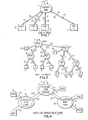
- FIG. 2 there is shown a simple hierarchy of nodes where several peripheral nodes 18, 20, 22 are connected to a central node 1. All the nodes are identical. Failure of the central node 1 does not affect the peripheral nodes. It only interrupts communication between them. Likewise, failure of a peripheral node does not affect the other nodes.
- the distributed star topology provides freedom in the selection of transmission links. Twisted pair, coax or optical fibers can be used. Note that this architecture has the flexibility to offer a low-cost network to low-speed users as well as providing extremely high bit rates supported by optical fibers, for instance. Also, network throughput is not limited by link distance. Any distance can be handled provided signal attenuation is compensated by repeaters when necessary. Note that in this inverted tree network a node may terminate lower-ranked nodes or ports. Ports 40, 42 in addition to 23, 25, 27, 29 can be selectively terminated in nodes of any hierarchical rank.
- the network access protocol for each port is to transmit packets at will. If the transmitted packet is not received back at the sender within a delay T, the packet was unsuccessful and the sending port can retransmit the packet at any time.
- the delay T constitutes the roundtrip propagation delay to the star node. Restated, each port can transmit packets at will and the only provision that has to be treated is the nondelivery of the packet.
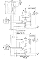
- FIG. 3 there is shown a block diagram of a standard node exhibiting the arbitration and locking facility with respect to inbound lines 33 and a broadcast facility with respect to outbound lines 31.
- each up-link 33 terminates in a signal conditioning circuits 41 for amplification and pulse reshaping.
- Each up-link may be driven by a counterpart port such as port 40 or node such as nodes 5.
- the up-link is terminated in a counterpart pulse reshaper such that the up-link for port 40 terminates in pulse shaper 101, while that for node 5 terminates in pulse shaper 102.
- each signal from a counterpart port or node is simultaneously applied to a corresponding control logic element (45, 47, 49) and a gate (51, 53, 55); i.e., signals from a pulse shaper 101 are placed on path 331 to node 107 where they may be concurrently applied to control logic 45 and as one of two inputs to gate 51.
- Each of the gates 51, 53, 55 is managed by the control logic and used to decide whether the packet transmitted by a port driving the control logic should capture the down-link.
- the down-links 31 are not switched but are coupled by line driver circuits 43 only. .
- Each control logic element has two stages.
- the first stage is a demand detect circuit (63, 65, 67) which monitors an up-link 33. Its function is to decide whether or not a packet is present on an up-link, as manifest on the counterpart path (331, 332, 33n). If a signal is present, a request line RQ (46, 48, 50) is raised and applied to a next stage denominated access control logic (57, 59, 61).
- Each access control logic element is interconnected by way of an access control bus 77.
- the outputs (71, 73, 75) of each counterpart access logic (57, 59, 61) regulates the gate (51, 53, 55) as a second input.
- each gate is dot OR'ed at a common junction 72 where it is outputed from the node over path 33 1 through amplifier 68 either to a hierarchically superior node (father node) over path 233 or looped back to be broadcast over down-link drivers 43 over a loop 3, amplifier 69 and common path 31'.
- a signal from a superior node is received over path 231 and applied directly to amplifier 69, path 31' to line drivers 43.
- the access control logic function 57 performs the channel capture function when the request line RQ 46 goes high, the access control logic checks if the down-link 31 is in use. If it is not, gate 51 for that up-link is opened and all other access control circuits 59, 61, are inhibited from capturing the down-link. Subsequently, when request line RQ 46 goes low, access control logic 57 will release control of the down-link. Significantly, packets can arrive on other up-links 33 while the down-link 31 is busy. These packets will simply be ignored.
- An advantage of this invention arises when a channel is released while other up-links are carrying packets. If a channel is allowed to be captured by one of the up-links 33, the packet transmitted will be truncated at the front since the signals were previously ignored during the prior busy period. Self-evidently, truncated messages cannot be correlated with their origins. This problem may be avoided by making channel capture a function of any new packet arrival on an up-link.
- the preferred embodiment does not instantaneously inhibit all other up-links as soon as a down-link is captured. This arises from the fact that signals take a finite time to be gated and propagated. For this reason, if two packets arrive at substantially the same time, they may both be allowed to use the down-links. This will result in a collision.
- a collision window is defined to be the period of time between the capture of a channel by one up-link until the time when all other up-links are inhibited.
- the collision window should typically last no more than twenty nanoseconds. Due to the narrowness of the collision window, the probability of collision should be extremely small. Indeed it can be treated as noise on the line.
- each node contains logic to detect collisions when they do occur and momentarily shut off all up-links without blocking off any new requests. Utilizing this logic, collisions can be detected and stopped within a few integral multiples of the collision window duration. Another consequence of the narrow collision window is that the propagation delay difference between points in the network would spread out the arrival times of retransmitted packets to any given node such that they will not collide indefinitely.
- a port 5 transmits signals to its node 18.
- Node 18 relays this signal to the central node 1.
- Node 1 transmits the signal back to all peripheral nodes 18, which in turn relay the signal back to all ports. In this way all ports, including the one from which a message originates, receive the message.
- the broadcast channel is used for this transmission medium.
- Ports recognize packets sent to them by inspecting a destination address. If this address matches with the port's address, the packet is accepted by the port. All other packets are ignored. Protocols for effectuating these tasks at the ports are not the subject of this invention. Reference may be made to Sproull, et al, "High Level Protocols", and Pouzin, et al, "A tutorial on Protocols", published respectively in the Proc. IEEE, Vol. 66, No. ll, November 1978, at pages 1371-85 and 1346-70. The following description is directed to the method and means by which the control logic within the nodes guarantees that only one port at a time can capture the shared broadcast channel for packet transmission purposes.
- FIG. 5 there is shown the access control logic portion of a node for regulating shared access of inbound lines.
- Figure 5 shows, among other aspects, the coupling between the individual control lines of bus 77 to each access control element 57 and 59.
- the control bus is electrically biased by control bias circuit 70 attached to predetermined voltage level V.
- the bus itself includes three control lines, 81, 83, and 85, respectively representing collision reset (CR), active users (AU) and channel idle (CI) conditions.
- the signal levels on the lines 81, 83, 85 of the control bus 77 are raised or lowered by such events as link enablement detected over path 87, 89 or the state of flip-flop 95.
- FIG. 6 binary signaling will be used.
- incoming signals are passed through amplifier 103 in pulse reshaper 101.
- amplifier 103 may use automatic gain control in combination with a low-pass filter 104 in a feedback path.
- Such self-adjusting amplification compensates the signal for link attenuation.
- the amplified signal wave form is then reshaped by trigger circuit 105.
- the transmission system has two modes, namely, that of a data mode and an idle mode.
- the data mode defines the interval within which data is transmitted-with any one of a number of DC free run-length limited codes, such as double frequency modulation code, (Manchester code).
- the idle mode is the interval during which links are assumed to be up without carrying data.
- two systems are set forth which differ during the idle mode. In the first system, an encoded pattern of ones is transmitted. In the second, no signal is impressed upon the path during the idle mode.
- node logic emphasizing an idle signal source and wrap-around logic for the system in which all ones are transmitted during idle mode.
- all links 33 from the connected ports 40, 42, 23, 25, etc. to the peripheral nodes carry continuous ones transmitted in one of the above- named time varying code forms.
- the RQ's 46, 48 are low and CI line 85 in the access control logic 57, 59 is high as per FIG. 9.
- An oscillator 131 inside each node then impresses a predetermined sequence of ones onto the link 233 to the root node 1. These ones are propagated to all inferior nodes by way of the wrap-around through the root node.
- the peripheral nodes relay this signal back to all ports.
- a continuous ones signal transmitted with the above codes, will appear on all links 31, 33 entering and leaving the nodes as long as no messages are transmitted.
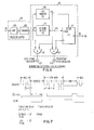
- a port indicates a transition from idle mode to data mode by transmitting a continuous mark for three bits times, as is shown in Figure 7.
- the end of a data mode is signaled by a port through the transmission of a continuous space for three bit periods. Only these two "code violations" are necessary to initiate and terminate message transfer through the network.
- This demand/end detector and line monitoring includes a pair of single-shot multivibrators 109 and 111 to which the reshaped pulses from circuit 101 are applied concurrently at junction 107.
- Single-shot multivibrator 111 detects the start and end of the data mode. Its negated output 113 is applied to the clock input of flip-flop 117. Since the demand and end flags are three-bit times in duration, the timing for single-shot multivibrator 111 is set there between.
- the demand detector 63 also includes lost signal indicator 123 and persistent high indicator 125. Given the absence of a signal at junction 107 and a positive level from single-shot multivibrator 109 at junction 115, then AND gate 119 will be turned on indicating a lost signal. Likewise, the presence of a signal at junction 107 and the absence of a signal at 115 turns AND gate 121 on indicative of a persistent high signal.
- Root node 1 contains the same access control logic 57 as the peripheral nodes. The root node firmly gives access to the broadcast channel 31 by relaying the port's signal back to all peripheral nodes which, in turn, relay them back to all the ports.
- RQ 46 goes low
- CI line 85 goes high
- oscillator 131 output is sent over gated path 135, 137, as well as 233 over junction 145 and amplifier 147.
- the outputs of gated amplifiers 51 and 53 are selectively placed upon junction 72 and are gated through 137 and presented to the up-link 233 over junction 145 and amplifier 147.
- the wrap-around logic 133 provides a down-link path connection through gated path 128, 129, 31' and amplifier 43 to down-link 31.
- the access control circuits are shown only by implication in that they take a RQ input and deliver a control output 71, 73 to a counterpart gate 51, 53.
- the node in Figure 8 is to be operated peripherally, then the downstream output from root node 1 is applied over path 231 and is gated straight through logic 133 to path 31', 43, 31.
- FIG. 9 there is shown a link continuity detector and an arrangement in which the transition from idle to data mode is simply triggered by a mark signal arriving at the node over an up-link 33.
- the incoming signals pass through the pulse reshapers onto the single shot multivibrators 149, 151. These single shots are connected to respective pulse reshapers 101 and 102 over paths 331 and 332.
- a transition for example, on line 331 to a mark level fires single shot 149.
- the time constants of these single shots are greater than two bit times for the di-phase or Manchester codes.
- a return on line 331 to a low level for longer than two bits time permits the single-shot 149 to reset. 3thls signals the end of the data mode.
- the RQ 46 line in Figure 9 is up high only during data mode.
- a root node detects the start of data mode in the same fashion as do the peripheral nodes.
- Figure 11 shows the timing and waveform for the three-level signal.
- a mid-level DC signal is transmitted as shown in this figure.
- a binary signal is transmitted using any DC free transmission code.
- the receive signal is processed according to the logic depicted in Figure 10. More particularly, the signal is amplified by an automatic gain control amplifier in element 103 which compensates using filter means 104 for any deviations from a standard average signal level caused by the transmission link, connector, and transmitter/ detector variations.
- thresholding elements 155 and 157 trigger pulse shaping flip-flop 105 in element 159. Transitions between the idle mode and the data mode are detected by the simple triggering of a loss signal as an output of flip-flop 107 setting single-shot multivibrator 153. Single-shot 153 then raises the RQ 46 input to the access control logic. The absence of a transmission in excess of two bit times signals the transition from data to idle mode and is detected also at junction 107 by single-shot 153.
- FIG 12 there is shown a node modified for ternary signaling compared with the binary signaling architecture set forth in Figure 8.
- the principal difference resides in the elimination of the circuit elements 131, 139, 141, and 143 and coupling CI line 85 to junction line 72 through gated amplifier 135 and to gated amplifier 147 through inverter 179.
- the transmission systems described above include extensive network monitoring functions with a minimum of additional hardware. These fault detection mechanisms in distributed star topology simplify the location and isolation of any failures of links and nodes.
- the transmission systems in which a signal is continuously transmitted during idle mode render either the loss of signal or a persistent high signal easy to detect.
- Single-shot 109 is edge triggered by transitions in the received and reshaped signal at junction 107.
- the time constant of single-shot 109 is preferably set to be two bit times or longer, depending on the desired delay after which the node reacts to an abnormal situation. Lack of transitions in the signal allow the single-shot 109 to reset. This clears flip-flop 117 and the RQ line 46 which then goes low. This response isolates the link and the port from the nodes access control logic 57. All other links remain operational. Relating the output of single-shot 109 to the signal, low or high, permits the detection of either loss of signal or persistent high signal level.
- single-shots 149, 151 also detect a persistent high-signal condition. Absence of transitions in the data signal on line 331 causes single-shot 149 to reset. The RQ line 46 goes low, which isolates the link and the port from the access logic. A persistent high situation at detector 63 will be indicated at the point 125 in Figs. 6, 10, when the data signal is high while the single-shot is reset. Because no signal is transmitted during idle mode, a different strategy may be used to detect link outages. A persistent low signal from a father node may be due either to the network idling or a failure. To discriminate between these conditions an idle message protocal is employed.
- a short packet (containing a series of pulses) is sent to the root node 1. Since transmission of signals requires that some signal be received after a given propagation delay, a failure would be detected if some signal is not received shortly.
- the logic within link continuity detectorvl61 performs this function. Since idle messages are sent only when the network is idling, no real efficiency is lost. Further, the transmission of an idle packet by any one network component inhibits the need for other network components to do the same.
- link detector 161 supervises the links between the peripheral nodes (31, 33) and the root nodes (231, 233).
- the timing circuits in link continuity detector 161 include single-shot 167 set for measuring the idle packet duration D 3 , single-shot 165 for measuring the maximum packet duration and idle interval D 2 , and single-shot 163 defining the maximum round-trip propagation delay.
- the link detector 161 operates in the following manner. When a signal from an up-link 33 is locked through to a further up-link path 33 through junction 72 and amplifier 68, DCI line 85 is raised and, among other functions, initiates the timing of single-shot 163 and 167. The former is triggered by flip-flop 171 and the latter by flip-flop chain 171 and 173. Single-shots 163 and 165 respectively measure maximum rough- trip propagation and idle packet duration. A signal present from root node 1 over path 231 and amplifier 69 turns off single-shots 163 by way of single-shot 169 and flip-flop 171 and turns off single-shot 167 through the additional flip-flop 173 and single-shot 165.
- a link failure is detected when no packet is perceived on the link from the root node within this delay. Packet arrival is detected in the same manner as on-links from ports to peripheral nodes.
- the network distributed star topology is built from identical nodes.
- any transmission medium can be used; that is, twisted pair, coax, optical fibers, microwaves and any mixtures thereof.
- This permits the construction of low cost networks for low data rate users, as well as networks exploiting the extreme bit rates supported by optical fibers.
- extremely simple random access broadcast protocol is invoked permitting ports to transmit at any time. The port only senses whether the packet transmitted reappears at the port receiver. If not, the port retries. In this manner, ports are freed from the carrier sense, collision detection, and randomized retransmission described in the Metcalfe reference.
- Each node in this invention functions only to connect a port demanding transmission to the broadcast channel, if the channel is idle.
- the nodes ignore the demand if the channel is busy. Simultaneous demands are ignored.
- the broadcast channel does not propagate truncated or colliding packets. Its bandwidth is utilized and is independent of network distance, packet length and data rate. Lastly, continuous monitoring of network links and nodes combined with immediate failure recovery and isolation renders the system highly reliable.
- the method comprises establishing a message-initiated path-lock up-link through the network from a demanding port to the root node by way of a first-come first-serve demand access discipline with arbitration at each distinct tree node level; and broadcast transmitting any message over all down-links fanning out from the root node as received over the up-link path connection to the root node.
- the network described is operable in a data and idle mode, and the method further comprises impressing signals indicative of the idle mode upon all up-links not transmitting messages; sensing at the up-links terminating each node any signal change from idle to data modes; and invoking the first-come first-serve demand access discipline at any given node upon sensing idle to data mode transition upon the up-links terminating in the given node.
Abstract
Description
- This invention relates to a method of transmitting data between ports of a communication system comprising a network of interconnected nodes, and to a communication system comprising a network of inter- connected nodes, and to a nodal unit for use as a node in a method or system as aforesaid.
- The invention arises out of the desire to improve data communication and in particular to improve packet switching. As may be recalled, a "packet" is defined by the CCITT as a group of binary digits including formatted data and call control signals which is switched as a composite whole. Relatedly, "packet switching" is taken to mean the transmission of data by means of addressed packets whereby a channel is occupied only during packet transmission. As pointed out both by Martin, "Telecommunications and the Computer", second edition, pages 457-481; 1976, and Davies, et al, "Communication networks for Computers",
Chapter 13; 1973, packet switching is intended primarily for real time machine-to-machine traffic. In this regard, a packet switching network of nodes and links is expected to deliver its packet in a fraction of a second, whereas a message switching system intended primarily for non-real time people-to- people traffic typically delivers its message in a fraction of an hour. - U.S. specification No. 3,914,743 (Fitch et al) discloses a data communication system comprising a control station, terminal stations and a communication network interconnecting the control and terminal stations. The communication network comprises a tree structure comprising sub-stations and duplex or two-way communication channels between the sub-stations. The control and terminal stations are respectively connected to their associated sub-station5by similar communication channels included in the network.
- Data and control words are transmitted down the tree structures from the control station to one of the sub-stations and are broadcast therefrom to all other sub-stations and terminal stations connected thereto. Any sub-station receiving data or control words from a preceeding sub-station in the tree structure broadcasts the received words to any other sub-stations or terminal station connected thereto. Thus, the network conveys data originating from the control station to all of the terminal stations simultaneously. The receiving terminal station is selected by the transmitted control words.
- Data is transmitted up the tree structure from any one of the terminal stations by transmission from the terminal station to its connected sub-station. At the sub-station the data from the or each connected substation is combined e.g. multiplexed and passed to the next sub-station up the tree. Thus each sub-station acts as a concentrator. This is continued until all the data is communicated to the control station.
- In the Fitch system a terminal station cannot communicate with another terminal station and only one terminal station transmits upstream at a time. If two stations were simultaneously to transmit upstreams in the Fitch system, the two would overwrite each other. No means for handling potential simultaneous transmission situations are disclosed in the Fitch specification.
- U.S. specification No. 4,063,220 (Metcalfe et al) discloses a data communication system comprising a multiplicity of terminal stations inter-connected by a communication network including one or more common data channels or highways. Each station has a unique address and the capacity to recognise its own address. A transmitting station broadcasts a data packet, including the destination address, over the entire network and each station connected thereto receives the transmitted data packet. The destination address is recognised by the destination station and the data packet accepted by that station. No acknowledgement signal is provided back to the transmitting station.
- Each terminal station in the Metcalfe system includes collision detection means. A collision is taken to occur when a terminal station starts to transmit data while other data is being passed over the network between two other terminal stations.
- In addition to the normal transmitting and receiving functions, the Metcalfe transceivers (transmitter/receiver) each provide a further control function for blocking transmission of data to avoid interference or collision with data being passed over the network between two other terminal stations. Thus, each transceiver comprises an arrangement, associated with the receiver, for blocking transmission by the transmitter unless the common channel or highway is in a quiescent state i.e. carrying no data. Thus, the Metcalfe systems waits for detection of a quiescent channel state before transmitting.
- However, in case a collision does occur, for example, if two other stations start to communicate between the instant that a station wishing to transmit detects the quiescent state and the instant it actually places data on the channel, the Metcalfe system has collision detection means at each station. The detection means comprise an XOR gate which receives as one input signal the transmitted data, delayed by an appropriate interval and as the other input signal, the data received at the station. The two inputs should be identical and the XOR gates output zero. In the event of a collision the terminal repeats its data transmission cycle, including waiting for a quiescent channel state, after a pseudo-random delay interval determined by reference to a random number generator.
- In any data communication system in which a bus is time shared among ports directly coupling the bus, two spatially separated ports must introduce a finite propagation delay when data is sent from one to the other. This results in a difficulty of ensuring queued access to the bus except by way of a serialized or external status indication to each port. Protocols involving waiting reduce the transmission rate in a high-speed packet transmission system, if waiting is required each time prior to transmission. This is exemplified in the hydraulic analogy of multiple ports accessing a shared pipe in which it would be necessary to drain the pipe prior to the insertion of a new message (water injection from one port destined to other ports). Such a bus/port logic arrangement is described in copending patent application No. 80102983.6.
- It is a first general object of the invention to provide an improved method of transmitting data and accordingly the invention provides a method of transmitting data between terminal ports of a communication system comprising a multiplicity of nodal units each having a plurality of ports through each of which data can be transmitted to and from the nodal unit and a network of duplex channels or data highways inter- connecting the nodal units in an inverted tree hierarchy, said method comprising tranmsitting the data as it is received at a first terminal port of one of the peripheral nodal units through the chain of nodal units and channels linking the one nodal unit with the root nodal unit, by successively establishing in each unit in the chain, progressing from the one unit to the root unit, a data path between the port at which data is received and the port from which data is transmitted through the linking channel to the next successive nodal unit in the chain; inhibiting, after each data path is established, the establishment of any other data path from any other port of the nodal unit to the transmitting port of the nodal unit; and, after receipt by the root nodal unit of at least some of the data, re-transmitting the data downwardly through the multiplicity of chains of nodal units and channels linking the root nodal unit with all the nodal units having terminal ports so that the data is broadcast downwardly through the network to each and every terminal port of the system.
- The invention also provides a method of transmitting messages through an inverted tree network of nodes and full duplex connecting links by ready ones of a plurality of transceiving ports individually coupling the network at selected nodes, each duplex link including an up-link and down-link respectively defining a signal path direction toward or away from the network root node, the method being characterised by establishing a signal path connection from a demanding port to a root node by reiteratively demand accessing of up-links on a mutually exclusive basis at each distinct tree node level by message transmission at will from demanding ports; broadcast transmitting any messages over all down-links fanning out from the root node as received over the up-link path connection; and confirming to the originating port that its message was delivered to the addressee port by receiving the down-link echo of the transmitted message by said originating port.
- The invention further provides a method for any-to-any port transmission of messages through an inverted tree network of nodes and full duplex connecting links by ready ones of a plurality of trasceiving ports attaching the network at selected nodes, each duplex link including an up-link and down-link which respectively define a signal path direction toward or away from the network root node, the method being characterised by establishing a message-initiated path lock up-link through the network from a demand port to the root node by way of a first-come first-serve demand access discipline with arbitration at each distinct tree node level, the establishing of the up-link path lock further including the step of ascertaining the idle or occupied activity status of each terminating up-link and down-link and invoking the demand access dise cipline upon sensing an activity transition from idle to occupied for those up-links terminating in the given node; and broadcast transmitting any message over all down-links fanning out from the root node as received over the up-link path connection to said root node.
- It is a second general object of the invention to provide an improved communication system and accordingly the invention also provides a data communication system comprising a multiplicity of nodal units, each nodal unit having a plurality of ports through each of which data can be transmitted into and out of the nodal unit, and a network of duplex channels or data highways inter-connecting the nodal units in an inverted tree structure, each channel comprising an up-link and a down-link respectively providing a data path towards or away from the root nodal unit of the tree structure, said system being characterised in that each nodal unit comprises means for detecting incoming data on the up-links connected thereto and for providing an onward transmission request signal in respect of any port at which such incoming data is so detected; gated circuit means connecting each port at which incoming data can be so detected with the port of the nodal unit connected by an up-link to another nodal unit or, for the root nodal unit, with the port connected to the down-link therefrom; and control means responsive to the onward transmission request signals for providing gating signals to the gated circuit means such that when one port receiving incoming data is connected to the transmitting port, no other receiving port can be connected thereto until the request signal associated with the one port ceases.
- The invention further provides a data communications system comprising a transmission medium formed from an inverted tree network of nodal units and full duplex connecting links, each duplex link including an up-link and a down-link respectively defining a signal path direction toward or away from the network root nodal unit, each up and down-link being in either an idle or occupied state and a plurality of transceiving units attached to the network at selected nodes, ready ones of the transceiving units transmitting messages at will; characterised in that each nodal unit includes means for ascertaining the activity status either idle or occupied of each terminating up-link and down-link; and means responsive to the first occuring ascertained state transition from idle to occupied among the up-links for completing an exclusive signal path connection to an outbound link only if the up-link is concurrently idle.
- It is a third general object of the invention to provide an improved nodal unit for use in performing a method, as aforesaid, and in a system, as aforesaid. Accordingly the invention also provides a nodal unit for use in a communication system comprising a multiplicity of such units connected in an inverted tree hierarchy by a network of duplex data channels, said unit comprising an up-port for connection by a duplex channel to a higher or same order hierarchial level and a plurality of down-ports for connection by a plurality of duplex channels to a lower hierarchial level or levels and said unit being characterised by comprising a plurality of individually switchable data paths inter-connecting the up and down ports; means, responsive to receipt of data at a down-port from a lower level, for providing a gating request signal requesting gating of the data path associated with the receiving down-port; access control means, common to all the data paths, for generating a gating signal in response to the first-to-be-provided gating request signal, for applying that gating signal to the data path inter-connecting the receiving down-port to the up-port and for inhibiting the generation of any other gating signal at least until the first-to-be-provided gating request signal has been discontinued; and circuit means inter-connecting the up-port and the down-ports so that data received at the up-port from a higher or same order hierarchial level is transmitted to all the down-ports.
- The foregoing general objects are satisfied in an embodiment utilizing a rooted tree topology. In a rooted tree network, all messages flow through the root (central) node from which they are broadcast to all ports in the network, incuding the originator of the message. There is, consequently, only one broadcast channel carrying all traffic between ports. The ports transmit messages at will. All nodes in the inverted tree hierarchy must be "captured" progressing upwardly towards the root node until the root node is captured. The root node broadcasts the message down the tree. Reception of an echo of the transmitted message confirms to the originating port that its message was delivered by the addressee port. Additionally, an end-to-end acknowledgement guarantees error-free reception of the message. Parenthetically, the terms "packet", as previously defined, and "message" will be used synonymously throughout the remainder of the text.
- The method of the invention utilizes a first-come, first-serve demand access discipline with arbitration in order to establish a path lock up-link through the network from a demanding port to a root node and broadcast transmission down-link over all fan-out paths. The invention, avoids collision by locking a path to a port. Furthermore, the first-come first-serve discipline and arbitration occurs at each distinct tree node level, and is implemented in part by XOR gating. In the preferred embodiments, collision can be made to occur only as a race condition between ports among the leading edges of messages. In this regard, a "race condition" is taken to mean the relative arrival time of the beginning of transmission, and in this system is defined by a window of not more than a few nanoseconds in width.
- In a demand access sytem, if a channel is relinquished while messages are being transmitted over other up-links, then seizure of the channel resulting in truncated message broadcasting can occur. This is prevented in this invention by conditioning channel seizure to the detection of a signal indicative of transition from idle to data transfer mode on a given up-link.
- The path lock is dependent only upon the message transmitting activity of a port. It does not require a port to listen prior to transmission as, for example, in Metcalfe. Further, unlike Fitch, the inverted tree topology of this invention does support any-to-any port transmission. Also, unlike Fitch, the presence of path locking avoids unintended seizure of a path or the conversion of a path transmission to noise.
- It should be observed, that the inverted rooted tree network with path locking gives the same degree of service to all messages. In this sense, the network is especially useful where the message flow spreads out over an entire region spanned by the network. Also, the invention improves network reliability. This arises from the fact that wrap-around logic located in the root and intermediate hierarchical nodes permits pathing for all uninterrupted branches. That is, a single node failure will not result in the entire network failing. The failure of any single node will only disconnect a counterpart subtree. In contrast, link failure in a ring network implies that the ring can only recover when it has the capability to reconfigure its topology. This requires redundant links and, therefore, additional link circuits.
- The invention will now be further described with reference to the accompanying drawings, in which:-
- Figure 1 depicts a star network of ports coupling a loop-back node over duplex links.
- Figure 2 shows an inverted tree hierarchy with the loop-back node as the root.
- Figure 3 sets forth a block diagram of a standard node exhibiting the arbitration locking facility with respect to inbound paths and the broadcast facility with respect to outbound paths.
- Figure 4 is the network data flow.
- Figure 5 illustrates the access control logic portion regulating shared access of inbound paths to a node by way of an access control bus.
- Figure 6 depicts an access request and activity monitoring portion for each path terminating in the node.
- Figure 7 is the timing and waveform diagram with respect to the request and monitoring activity of the logic shown in Figure 6.
- Figure 8 exhibits the idle signal and wrap-around logic in the node.
- Figure 9 shows a link continuity detector.
- Figure 10 sets forth an access request activity monitoring for ternary level signals.
- Figure 11 is the timing and waveform diagram with respect to the ternary level signals of the arrangement shown in Figure 10.
- Figure 12 illustrates the node modified for ternary signaling.
- Referring now to Figure 1, there is shown a
node 1 with a number ofports inbound link 33 path locked therethrough and broadcasts on all outgoinglinks 31. - Each attached port can start a message transmission at any time. The control method and means inside each node guarantees that only one message can pass through the network at a time.
- The logic in each node is capable of inhibiting the propagation of all packets from those ports which initiate a transmission, while said node is otherwise active. After some delay equal to the round trip propagation time, if a shut-out port detects that its transmission was unsuccessful then it may reinitiate message transmission. If packets (messages) from two or more ports arrive at a node simultaneously, for example, within a twenty nanosecond interval, then the ports are both shut out. In this way colliding packets do not get access to the broadcast channel. Repetition of this simultaneous initiation is practically impossible because of the minimum interval defined by the time window and by the differences in the local port clocks and propagation delays.
- Referring now to Figure 2, there is shown a simple hierarchy of nodes where several
peripheral nodes central node 1. All the nodes are identical. Failure of thecentral node 1 does not affect the peripheral nodes. It only interrupts communication between them. Likewise, failure of a peripheral node does not affect the other nodes. Advantageously, the distributed star topology provides freedom in the selection of transmission links. Twisted pair, coax or optical fibers can be used. Note that this architecture has the flexibility to offer a low-cost network to low-speed users as well as providing extremely high bit rates supported by optical fibers, for instance. Also, network throughput is not limited by link distance. Any distance can be handled provided signal attenuation is compensated by repeaters when necessary. Note that in this inverted tree network a node may terminate lower-ranked nodes or ports.Ports - As previously mentioned, the network access protocol for each port is to transmit packets at will. If the transmitted packet is not received back at the sender within a delay T, the packet was unsuccessful and the sending port can retransmit the packet at any time. In this discussion the delay T constitutes the roundtrip propagation delay to the star node. Restated, each port can transmit packets at will and the only provision that has to be treated is the nondelivery of the packet.
- Referring now to Figure 3, there is shown a block diagram of a standard node exhibiting the arbitration and locking facility with respect to
inbound lines 33 and a broadcast facility with respect tooutbound lines 31. - In Figure 3, each up-
link 33 terminates in asignal conditioning circuits 41 for amplification and pulse reshaping. Each up-link may be driven by a counterpart port such asport 40 or node such asnodes 5. The up-link is terminated in a counterpart pulse reshaper such that the up-link forport 40 terminates inpulse shaper 101, while that fornode 5 terminates inpulse shaper 102. Subsequent to pulse reshaping, each signal from a counterpart port or node is simultaneously applied to a corresponding control logic element (45, 47, 49) and a gate (51, 53, 55); i.e., signals from apulse shaper 101 are placed onpath 331 tonode 107 where they may be concurrently applied to controllogic 45 and as one of two inputs togate 51. Each of thegates links 31 are not switched but are coupled byline driver circuits 43 only. . - Each control logic element has two stages. The first stage is a demand detect circuit (63, 65, 67) which monitors an up-
link 33. Its function is to decide whether or not a packet is present on an up-link, as manifest on the counterpart path (331, 332, 33n). If a signal is present, a request line RQ (46, 48, 50) is raised and applied to a next stage denominated access control logic (57, 59, 61). Each access control logic element is interconnected by way of anaccess control bus 77. The outputs (71, 73, 75) of each counterpart access logic (57, 59, 61) regulates the gate (51, 53, 55) as a second input. In turn, the output of each gate is dot OR'ed at acommon junction 72 where it is outputed from the node overpath 331 throughamplifier 68 either to a hierarchically superior node (father node) overpath 233 or looped back to be broadcast over down-link drivers 43 over aloop 3,amplifier 69 and common path 31'. Relatedly, a signal from a superior node is received overpath 231 and applied directly toamplifier 69, path 31' toline drivers 43. - The access
control logic function 57 performs the channel capture function when therequest line RQ 46 goes high, the access control logic checks if the down-link 31 is in use. If it is not,gate 51 for that up-link is opened and all otheraccess control circuits request line RQ 46 goes low,access control logic 57 will release control of the down-link. Significantly, packets can arrive on other up-links 33 while the down-link 31 is busy. These packets will simply be ignored. - An advantage of this invention arises when a channel is released while other up-links are carrying packets. If a channel is allowed to be captured by one of the up-
links 33, the packet transmitted will be truncated at the front since the signals were previously ignored during the prior busy period. Self-evidently, truncated messages cannot be correlated with their origins. This problem may be avoided by making channel capture a function of any new packet arrival on an up-link. - As may be surmised, the preferred embodiment does not instantaneously inhibit all other up-links as soon as a down-link is captured. This arises from the fact that signals take a finite time to be gated and propagated. For this reason, if two packets arrive at substantially the same time, they may both be allowed to use the down-links. This will result in a collision. In this regard, a collision window is defined to be the period of time between the capture of a channel by one up-link until the time when all other up-links are inhibited. In the method and means of this invention, the collision window should typically last no more than twenty nanoseconds. Due to the narrowness of the collision window, the probability of collision should be extremely small. Indeed it can be treated as noise on the line.
- As will be subsequently described, each node contains logic to detect collisions when they do occur and momentarily shut off all up-links without blocking off any new requests. Utilizing this logic, collisions can be detected and stopped within a few integral multiples of the collision window duration. Another consequence of the narrow collision window is that the propagation delay difference between points in the network would spread out the arrival times of retransmitted packets to any given node such that they will not collide indefinitely.
- Referring now to Figure 2, and at the same time using the dotted
line connections root node 1 of this tree network operates identically to the single star network described in Figure 1. Each packet transmitted by aport 5 will travel through a number of nodes until it reaches theroot node 1 where it is broadcast to all other ports. All the nodes in the tree are identical. - Referring now to Figure 4, there is shown the network data flow. A
port 5 transmits signals to itsnode 18.Node 18 relays this signal to thecentral node 1.Node 1 transmits the signal back to allperipheral nodes 18, which in turn relay the signal back to all ports. In this way all ports, including the one from which a message originates, receive the message. The broadcast channel is used for this transmission medium. - Ports recognize packets sent to them by inspecting a destination address. If this address matches with the port's address, the packet is accepted by the port. All other packets are ignored. Protocols for effectuating these tasks at the ports are not the subject of this invention. Reference may be made to Sproull, et al, "High Level Protocols", and Pouzin, et al, "A Tutorial on Protocols", published respectively in the Proc. IEEE, Vol. 66, No. ll, November 1978, at pages 1371-85 and 1346-70. The following description is directed to the method and means by which the control logic within the nodes guarantees that only one port at a time can capture the shared broadcast channel for packet transmission purposes.
- Referring now to Figure 5, there is shown the access control logic portion of a node for regulating shared access of inbound lines. Figure 5 shows, among other aspects, the coupling between the individual control lines of
bus 77 to eachaccess control element control bias circuit 70 attached to predetermined voltage level V. The bus itself includes three control lines, 81, 83, and 85, respectively representing collision reset (CR), active users (AU) and channel idle (CI) conditions. The signal levels on thelines control bus 77 are raised or lowered by such events as link enablement detected overpath 87, 89 or the state of flip-flop 95. - When the
request line 46 becomes high and the channel is idle, i.e.line 85 is high and the link enable line 87 is raised. Consequently,gate 91 is enabled, raisingpath 71 high. Simultaneously, channelidle line 85 is then lowered so as to inhibit any new requests and reduce the voltage on the activeuser control line 83. The voltage on theline 83 is constantly monitored to detect if it falls below a certain threshold. When this happens it means that more than one user is active. The low voltage online 83 results in collision resetline 81 being forced low to shut off all users until the collision stops. Since the D flip-flop 95 is rising edge clocked, channel capture is possible only when the packet first arrives. If channel capture is unsuccessful at that time, the subsequent idling of the channel does not allow capture by this partially discarded packet. - Referring now to Figures 3, 6, 7, and 8, the following description will reference a system using either electrical or optical transmission links. In FIG. 6, binary signaling will be used. At each node, incoming signals are passed through
amplifier 103 inpulse reshaper 101. As may be incidentally seen in Figure 10,amplifier 103 may use automatic gain control in combination with a low-pass filter 104 in a feedback path. Such self-adjusting amplification compensates the signal for link attenuation. The amplified signal wave form is then reshaped bytrigger circuit 105. - The transmission system has two modes, namely, that of a data mode and an idle mode. The data mode defines the interval within which data is transmitted-with any one of a number of DC free run-length limited codes, such as double frequency modulation code, (Manchester code). The idle mode is the interval during which links are assumed to be up without carrying data. In this invention, two systems are set forth which differ during the idle mode. In the first system, an encoded pattern of ones is transmitted. In the second, no signal is impressed upon the path during the idle mode.
- Referring now to Figure 8, there is shown node logic emphasizing an idle signal source and wrap-around logic for the system in which all ones are transmitted during idle mode. In the absence of any message, all
links 33 from theconnected ports CI line 85 in theaccess control logic oscillator 131 inside each node then impresses a predetermined sequence of ones onto thelink 233 to theroot node 1. These ones are propagated to all inferior nodes by way of the wrap-around through the root node. The peripheral nodes relay this signal back to all ports. Thus, a continuous ones signal, transmitted with the above codes, will appear on alllinks - A port indicates a transition from idle mode to data mode by transmitting a continuous mark for three bits times, as is shown in Figure 7. The end of a data mode is signaled by a port through the transmission of a continuous space for three bit periods. Only these two "code violations" are necessary to initiate and terminate message transfer through the network.
- Referring now to Figure 6, when taken together with Figure 7, there is shown the access request and activity monitoring portion for each line terminating in a control logic element in a node. This demand/end detector and line monitoring includes a pair of single-
shot multivibrators circuit 101 are applied concurrently atjunction 107. Single-shot multivibrator 111 detects the start and end of the data mode. Its negatedoutput 113 is applied to the clock input of flip-flop 117. Since the demand and end flags are three-bit times in duration, the timing for single-shot multivibrator 111 is set there between. This is a unique sequence as can be seen in the timing diagram of Figure 7 where both the idle pattern and the data pattern requires signal level transitions after two bit times in duration. Note, that theRQ output 46 from flip-flop 117 is raised when single-shot 111 changes state and is lowered only when single-shot 111 again changes state, indicative of its detection of an end-of-message signal of three bit times at the same signal level. Also note, thatRQ 46 is connected to accesscontrol circuit 57. - The
demand detector 63 also includes lostsignal indicator 123 and persistenthigh indicator 125. Given the absence of a signal atjunction 107 and a positive level from single-shot multivibrator 109 atjunction 115, then ANDgate 119 will be turned on indicating a lost signal. Likewise, the presence of a signal atjunction 107 and the absence of a signal at 115 turns ANDgate 121 on indicative of a persistent high signal. - Referring again to Figure 8 when taken together with FIG. 4, when a port initiates a message transmission its RQ line goes high. If the port succeeds in getting access to the
link 233 from theperipheral node 18 and hence to theroot node 1,CI line 85 in theaccess control logic 57, as shown in Figure 5, goes low and disconnects theoscillator 131 from thelink 233 to the father by disablinggate 135. At the same time, the transition online 85 fires a single-shot multivibrator 139 throughinverter gate 141 which overgating path junction 145, andamplifier 147, signals to theroot node 1 overpath 233 that a transition has occurred from the idle mode to the data mode. -
Root node 1 contains the sameaccess control logic 57 as the peripheral nodes. The root node firmly gives access to thebroadcast channel 31 by relaying the port's signal back to all peripheral nodes which, in turn, relay them back to all the ports. At the end of the data mode,RQ 46 goes low,CI line 85 goes high, and theoscillator 131 is again switched onto the outgoing links. In thisregard oscillator 131 output is sent overgated path junction 145 andamplifier 147. - In passing, it should be observed that the outputs of
gated amplifiers junction 72 and are gated through 137 and presented to the up-link 233 overjunction 145 andamplifier 147. In the event that the node operates as a root node, then the wrap-aroundlogic 133 provides a down-link path connection throughgated path amplifier 43 to down-link 31. In Figure 8, the access control circuits are shown only by implication in that they take a RQ input and deliver acontrol output counterpart gate root node 1 is applied overpath 231 and is gated straight throughlogic 133 topath - Referring now to Figure 9, there is shown a link continuity detector and an arrangement in which the transition from idle to data mode is simply triggered by a mark signal arriving at the node over an up-
link 33. The incoming signals pass through the pulse reshapers onto thesingle shot multivibrators paths line 331 to a mark level firessingle shot 149. The time constants of these single shots are greater than two bit times for the di-phase or Manchester codes. A return online 331 to a low level for longer than two bits time permits the single-shot 149 to reset. 3thls signals the end of the data mode. TheRQ 46 line in Figure 9 is up high only during data mode. A root node detects the start of data mode in the same fashion as do the peripheral nodes. - For implementing an inverted tree network of nodes.and interconnecting duplex links with optical fibers it has been found advantageous to utilize three-level ternary signaling. In this regard, reference should be made to Figures 8, 10, 11. Figure 11 shows the timing and waveform for the three-level signal. During idle modes, a mid-level DC signal is transmitted as shown in this figure. However, during data mode, a binary signal is transmitted using any DC free transmission code. The receive signal is processed according to the logic depicted in Figure 10. More particularly, the signal is amplified by an automatic gain control amplifier in
element 103 which compensates using filter means 104 for any deviations from a standard average signal level caused by the transmission link, connector, and transmitter/ detector variations. The output ofthresholding elements flop 105 inelement 159. Transitions between the idle mode and the data mode are detected by the simple triggering of a loss signal as an output of flip-flop 107 setting single-shot multivibrator 153. Single-shot 153 then raises theRQ 46 input to the access control logic. The absence of a transmission in excess of two bit times signals the transition from data to idle mode and is detected also atjunction 107 by single-shot 153. - Referring now to Figure 12, there is shown a node modified for ternary signaling compared with the binary signaling architecture set forth in Figure 8. The principal difference resides in the elimination of the
circuit elements coupling CI line 85 tojunction line 72 throughgated amplifier 135 and togated amplifier 147 throughinverter 179. - The transmission systems described above include extensive network monitoring functions with a minimum of additional hardware. These fault detection mechanisms in distributed star topology simplify the location and isolation of any failures of links and nodes. The transmission systems in which a signal is continuously transmitted during idle mode render either the loss of signal or a persistent high signal easy to detect.
- Referring again to Figure 6, the detection of persistent high-signal level is indicated at
junction 125 and signal loss at 123. Single-shot 109 is edge triggered by transitions in the received and reshaped signal atjunction 107. The time constant of single-shot 109 is preferably set to be two bit times or longer, depending on the desired delay after which the node reacts to an abnormal situation. Lack of transitions in the signal allow the single-shot 109 to reset. This clears flip-flop 117 and theRQ line 46 which then goes low. This response isolates the link and the port from the nodesaccess control logic 57. All other links remain operational. Relating the output of single-shot 109 to the signal, low or high, permits the detection of either loss of signal or persistent high signal level. - Referring again to Figure 10, there is set out the failure detection circuit for the three-level transmission system. Only one single-
shot 153 is used for detecting transitions between idle and data modes as well as link failures. Lack of transitions in the signal waveform lets the signal-shot 153 reset, after which,RQ line 46 goes low. Inspection of thecomparative outputs gates - Referring now to Figure 9, single-
shots line 331 causes single-shot 149 to reset. TheRQ line 46 goes low, which isolates the link and the port from the access logic. A persistent high situation atdetector 63 will be indicated at thepoint 125 in Figs. 6, 10, when the data signal is high while the single-shot is reset. Because no signal is transmitted during idle mode, a different strategy may be used to detect link outages. A persistent low signal from a father node may be due either to the network idling or a failure. To discriminate between these conditions an idle message protocal is employed. Whenever the incoming link from a father node has idled for a given period of time, a short packet (containing a series of pulses) is sent to theroot node 1. Since transmission of signals requires that some signal be received after a given propagation delay, a failure would be detected if some signal is not received shortly. The logic within link continuity detectorvl61 performs this function. Since idle messages are sent only when the network is idling, no real efficiency is lost. Further, the transmission of an idle packet by any one network component inhibits the need for other network components to do the same. - Referring again to Figure 9,
link detector 161 supervises the links between the peripheral nodes (31, 33) and the root nodes (231, 233). The timing circuits inlink continuity detector 161 include single-shot 167 set for measuring the idle packet duration D3, single-shot 165 for measuring the maximum packet duration and idle interval D2, and single-shot 163 defining the maximum round-trip propagation delay. - The
link detector 161 operates in the following manner. When a signal from an up-link 33 is locked through to a further up-link path 33 throughjunction 72 andamplifier 68,DCI line 85 is raised and, among other functions, initiates the timing of single-shot flop 171 and the latter by flip-flop chain shots root node 1 overpath 231 andamplifier 69 turns off single-shots 163 by way of single-shot 169 and flip-flop 171 and turns off single-shot 167 through the additional flip-flop 173 and single-shot 165. - A link failure is detected when no packet is perceived on the link from the root node within this delay. Packet arrival is detected in the same manner as on-links from ports to peripheral nodes.
- Failure of the communication between the root and peripheral nodes, either loss of signal or persistent high-level signal, or root node inability to return packets to peripheral nodes, results in automatic wrap-around of the signal through
element 133, Figure 8. Signals continue to go to the root node and at the same time they are directly transmitted back from the peripheral node to the port. This mechanism keeps peripheral nodes operational when communication with the root node has become impossible. As soon as valid signals are received from the root node, the wrap-around function in the peripheral nodes terminates. - In conclusion, it should be noted that the network distributed star topology is built from identical nodes. In this invention any transmission medium can be used; that is, twisted pair, coax, optical fibers, microwaves and any mixtures thereof. This permits the construction of low cost networks for low data rate users, as well as networks exploiting the extreme bit rates supported by optical fibers. Relatedly, extremely simple random access broadcast protocol is invoked permitting ports to transmit at any time. The port only senses whether the packet transmitted reappears at the port receiver. If not, the port retries. In this manner, ports are freed from the carrier sense, collision detection, and randomized retransmission described in the Metcalfe reference.
- Each node in this invention functions only to connect a port demanding transmission to the broadcast channel, if the channel is idle. The nodes ignore the demand if the channel is busy. Simultaneous demands are ignored. The broadcast channel does not propagate truncated or colliding packets. Its bandwidth is utilized and is independent of network distance, packet length and data rate. Lastly, continuous monitoring of network links and nodes combined with immediate failure recovery and isolation renders the system highly reliable.
- As will be apparent there has been described herein a method for any-to-any port transmission of messages through an inverted tree network of nodes and full duplex connecting links by ready ones of a plurality of transceiving ports individually coupling the network at selected nodes, each duplex link including an up-link and down-link respectively defining a signal path direction toward or away from the network root node. The method comprises establishing a message-initiated path-lock up-link through the network from a demanding port to the root node by way of a first-come first-serve demand access discipline with arbitration at each distinct tree node level; and broadcast transmitting any message over all down-links fanning out from the root node as received over the up-link path connection to the root node. The network described is operable in a data and idle mode, and the method further comprises impressing signals indicative of the idle mode upon all up-links not transmitting messages; sensing at the up-links terminating each node any signal change from idle to data modes; and invoking the first-come first-serve demand access discipline at any given node upon sensing idle to data mode transition upon the up-links terminating in the given node.
Claims (13)
Applications Claiming Priority (2)
| Application Number | Priority Date | Filing Date | Title |
|---|---|---|---|
| US96356 | 1979-11-21 | ||
| US06/096,356 US4347498A (en) | 1979-11-21 | 1979-11-21 | Method and means for demand accessing and broadcast transmission among ports in a distributed star network |
Publications (2)
| Publication Number | Publication Date |
|---|---|
| EP0029502A1 true EP0029502A1 (en) | 1981-06-03 |
| EP0029502B1 EP0029502B1 (en) | 1984-03-07 |
Family
ID=22256988
Family Applications (1)
| Application Number | Title | Priority Date | Filing Date |
|---|---|---|---|
| EP80106266A Expired EP0029502B1 (en) | 1979-11-21 | 1980-10-15 | A method of transmitting data between ports of a communication system comprising a network of interconnected nodes, and a communication system comprising a network of interconnected nodes, and a nodal unit for use as a node in a method or system as aforesaid |
Country Status (5)
| Country | Link |
|---|---|
| US (1) | US4347498A (en) |
| EP (1) | EP0029502B1 (en) |
| JP (2) | JPS5840384B2 (en) |
| CA (1) | CA1141838A (en) |
| DE (1) | DE3066854D1 (en) |
Cited By (9)
| Publication number | Priority date | Publication date | Assignee | Title |
|---|---|---|---|---|
| EP0069438A2 (en) * | 1981-04-01 | 1983-01-12 | Teradata Corporation | A multiprocessor system, a system and method for intercommunicating between processors, a system for effecting data transfer, a system for controlling routing of messages, and an arrangement for ascertaining a global state of readiness of a system |
| EP0070083A2 (en) * | 1981-04-01 | 1983-01-19 | Teradata Corporation | Computing apparatus and method of processing message packets |
| EP0073352A2 (en) * | 1981-08-14 | 1983-03-09 | Oki Electric Industry Company, Limited | A data communication system |
| GB2131252A (en) * | 1982-12-02 | 1984-06-13 | Western Electric Co | System and method for controlling a multiple access data communications system |
| EP0110390A2 (en) * | 1982-12-02 | 1984-06-13 | Western Electric Company, Incorporated | Collision avoidance circuit for packet switched communication system |
| EP0170799A1 (en) * | 1984-06-27 | 1986-02-12 | International Business Machines Corporation | Switching systems |
| EP0173508A2 (en) * | 1984-08-31 | 1986-03-05 | Xerox Corporation | Local area network |
| EP0195595A2 (en) * | 1985-03-21 | 1986-09-24 | AT&T Corp. | Local area network |
| EP0237582A1 (en) * | 1985-09-03 | 1987-09-23 | The University Of Toronto Innovations Foundation | Local area networks |
Families Citing this family (137)
| Publication number | Priority date | Publication date | Assignee | Title |
|---|---|---|---|---|
| FR2470996B1 (en) | 1979-11-30 | 1986-01-31 | Quinquis Jean Paul | IMPROVEMENTS IN MULTIPROCESSOR ELECTRONIC SYSTEMS FOR PROCESSING DIGITAL AND LOGICAL DATA |
| US4488151A (en) * | 1981-12-10 | 1984-12-11 | Burroughs Corporation | Arbiter switch for a concurrent network of processors |
| US4945471A (en) * | 1981-04-01 | 1990-07-31 | Teradata Corporation | Message transmission system for selectively transmitting one of two colliding messages based on contents thereof |
| US4814979A (en) * | 1981-04-01 | 1989-03-21 | Teradata Corporation | Network to transmit prioritized subtask pockets to dedicated processors |
| US4441162A (en) * | 1981-04-22 | 1984-04-03 | Pitney Bowes Inc. | Local network interface with control processor & DMA controller for coupling data processing stations to common serial communications medium |
| US4597075A (en) * | 1981-08-21 | 1986-06-24 | Italtel-Societa Italiana Telecomunicazioni S.P.A. | Modular switching network for telecommunication system |
| US4430651A (en) | 1981-08-27 | 1984-02-07 | Burroughs Corporation | Expandable and contractible local area network system |
| FR2513048A1 (en) * | 1981-09-16 | 1983-03-18 | Seinep Ste Electro Nord Est Pa | METHOD OF TELECOMMUNICATION BY AIRWAY AND DEVICE FOR IMPLEMENTING SAID METHOD |
| US4451827A (en) * | 1981-09-22 | 1984-05-29 | The Johns Hopkins University | Local area communication network |
| US4965825A (en) | 1981-11-03 | 1990-10-23 | The Personalized Mass Media Corporation | Signal processing apparatus and methods |
| USRE47642E1 (en) | 1981-11-03 | 2019-10-08 | Personalized Media Communications LLC | Signal processing apparatus and methods |
| US7831204B1 (en) | 1981-11-03 | 2010-11-09 | Personalized Media Communications, Llc | Signal processing apparatus and methods |
| JPS5916453B2 (en) * | 1981-12-03 | 1984-04-16 | 株式会社リコー | Optical data communication system |
| US4472712A (en) * | 1982-03-05 | 1984-09-18 | At&T Bell Laboratories | Multipoint data communication system with local arbitration |
| US4464658A (en) * | 1982-03-05 | 1984-08-07 | At&T Laboratories | Multipoint data communication system with collision detection |
| US4516239A (en) * | 1982-03-15 | 1985-05-07 | At&T Bell Laboratories | System, apparatus and method for controlling a multiple access data communications system including variable length data packets and fixed length collision-free voice packets |
| US4481626A (en) * | 1982-05-05 | 1984-11-06 | Xerox Corporation | Transceiver multiplexor |
| DE3268099D1 (en) * | 1982-06-15 | 1986-02-06 | Ibm | Method and apparatus for controlling access to a communication network |
| US4475188A (en) * | 1982-09-02 | 1984-10-02 | Burroughs Corp. | Four way arbiter switch for a five port module as a node in an asynchronous speed independent network of concurrent processors |
| US4484325A (en) * | 1982-09-02 | 1984-11-20 | Burroughs Corporation | Four way selector switch for a five port module as a node asynchronous speed independent network of concurrent processors |
| US4482996A (en) * | 1982-09-02 | 1984-11-13 | Burroughs Corporation | Five port module as a node in an asynchronous speed independent network of concurrent processors |
| US4570162A (en) * | 1982-09-13 | 1986-02-11 | The University Of Toronto Innovations Foundation | Local area networks |
| US4755988A (en) * | 1983-05-04 | 1988-07-05 | Cxc Corporation | Data communications switching device having multiple switches operating at plural selectable data rates |
| US4587651A (en) * | 1983-05-04 | 1986-05-06 | Cxc Corporation | Distributed variable bandwidth switch for voice, data, and image communications |
| WO1984004638A1 (en) * | 1983-05-12 | 1984-11-22 | American Telephone & Telegraph | Communication network |
| CA1203876A (en) * | 1983-06-29 | 1986-04-29 | Conrad Lewis | Peripheral control for a digital telephone system |
| US4905219A (en) * | 1983-09-22 | 1990-02-27 | Aetna Life Insurance Company | Three level distributed control for networking I/O devices |
| US4532625A (en) * | 1983-10-17 | 1985-07-30 | The United States Of America As Represented By The Secretary Of The Army | Communications network status information system |
| JPS60116245A (en) * | 1983-11-28 | 1985-06-22 | Seiichi Miyazaki | Tree form data transmission system |
| US4602364A (en) * | 1984-04-23 | 1986-07-22 | Codex Corporation | Local area data communication network |
| US4592048A (en) * | 1984-05-03 | 1986-05-27 | At&T Bell Laboratories | Integrated packet switching and circuit switching system |
| US4596010A (en) * | 1984-05-03 | 1986-06-17 | At&T Bell Laboratories | Distributed packet switching arrangement |
| DE3476503D1 (en) * | 1984-06-01 | 1989-03-02 | Bell Telephone Mfg | Multiple memory loading system |
| AU591057B2 (en) * | 1984-06-01 | 1989-11-30 | Digital Equipment Corporation | Local area network for digital data processing system |
| US4679186A (en) * | 1984-09-26 | 1987-07-07 | American Telephone And Telegraph Company, At&T Bell Laboratories | Alternate self-routing packet switching node having fault detection capabilities |
| US4630254A (en) * | 1984-10-26 | 1986-12-16 | Trw Inc. | Controlled star network |
| US4674085A (en) * | 1985-03-21 | 1987-06-16 | American Telephone And Telegraph Co. | Local area network |
| US4641302A (en) * | 1985-06-24 | 1987-02-03 | Racal Data Communications Inc. | High speed packet switching arrangement |
| US4706080A (en) * | 1985-08-26 | 1987-11-10 | Bell Communications Research, Inc. | Interconnection of broadcast networks |
| US4701756A (en) * | 1985-09-10 | 1987-10-20 | Burr William E | Fault-tolerant hierarchical network |
| US4781427A (en) * | 1985-09-19 | 1988-11-01 | The Mitre Corporation | Active star centered fiber optic local area network |
| US4825435A (en) * | 1985-11-08 | 1989-04-25 | Digital Equipment Corp. | Multiport repeater |
| GB8528892D0 (en) * | 1985-11-23 | 1986-01-02 | Int Computers Ltd | Multi-node data processing system |
| US4925311A (en) * | 1986-02-10 | 1990-05-15 | Teradata Corporation | Dynamically partitionable parallel processors |
| FR2594615B1 (en) * | 1986-02-20 | 1988-06-17 | France Etat | DEVICE FOR DEMULTIPLEXING PACKETS OF A MAC / PACKET BROADCASTING SIGNAL |
| USRE33650E (en) * | 1986-07-30 | 1991-07-30 | University Of Toronto Innovations Foundation | Deterministic access protocol local area network |
| US4773069A (en) * | 1986-07-30 | 1988-09-20 | Boulton P I P | Robust rooted tree network |
| US4901342A (en) * | 1986-08-22 | 1990-02-13 | Jones Reese M | Local area network connecting computer products via long telephone lines |
| US4839887A (en) * | 1986-09-18 | 1989-06-13 | Ricoh Company, Ltd. | Node apparatus for communication network having multi-conjunction architecture |
| US5189414A (en) * | 1986-09-30 | 1993-02-23 | Kabushiki Kaisha Toshiba | Network system for simultaneously coupling pairs of nodes |
| JPS63296534A (en) * | 1987-05-28 | 1988-12-02 | Nec Corp | Directional path establishing system |
| US4833677A (en) * | 1987-06-12 | 1989-05-23 | The United States Of America As Represented By The Secretary Of The Air Force | Easily testable high speed architecture for large RAMS |
| US5463619A (en) * | 1987-08-17 | 1995-10-31 | U.S. Philips Corporation | Local communication bus system comprising a set of interconnected devices, a control bus, and a set of signal interconnections, and a device and a switchbox for use in such system |
| US4983962A (en) * | 1987-09-14 | 1991-01-08 | Hammerstrom Daniel W | Neural-model, computational architecture employing broadcast hierarchy and hypergrid, point-to-point communication |
| US4887076A (en) * | 1987-10-16 | 1989-12-12 | Digital Equipment Corporation | Computer interconnect coupler for clusters of data processing devices |
| US4811337A (en) * | 1988-01-15 | 1989-03-07 | Vitalink Communications Corporation | Distributed load sharing |
| JP2584647B2 (en) * | 1988-01-28 | 1997-02-26 | 株式会社リコー | Node device of communication network |
| US4977455B1 (en) * | 1988-07-15 | 1993-04-13 | System and process for vcr scheduling | |
| US4825504A (en) * | 1988-08-24 | 1989-05-02 | Lee-Rowan Company | End cap |
| US5115495A (en) * | 1988-10-18 | 1992-05-19 | The Mitre Corporation | Communications network system using full-juncture and partial-juncture station status information for alternate-path distance-vector routing |
| US4918617A (en) * | 1988-11-10 | 1990-04-17 | Oregon Graduate Center | Neural-model computational system with multi-directionally overlapping broadcast regions |
| US5027342A (en) * | 1989-05-03 | 1991-06-25 | The University Of Toronto Innovations Foundation | Local area network |
| FR2649574B1 (en) * | 1989-07-04 | 1991-10-18 | Rce Sa | COMMUNICATION NETWORK BETWEEN USER EQUIPMENT |
| GB8923351D0 (en) * | 1989-10-17 | 1989-12-06 | Stc Plc | Multifrequency optical network |
| US5727060A (en) * | 1989-10-30 | 1998-03-10 | Starsight Telecast, Inc. | Television schedule system |
| US7748018B2 (en) * | 1989-10-30 | 2010-06-29 | Starsight Telecast, Inc. | Arranging channel indicators in a television schedule system |
| US5287534A (en) * | 1990-01-04 | 1994-02-15 | Digital Equipment Corporation | Correcting crossover distortion produced when analog signal thresholds are used to remove noise from signal |
| US5226120A (en) * | 1990-05-21 | 1993-07-06 | Synoptics Communications, Inc. | Apparatus and method of monitoring the status of a local area network |
| US5301333A (en) * | 1990-06-14 | 1994-04-05 | Bell Communications Research, Inc. | Tree structured variable priority arbitration implementing a round-robin scheduling policy |
| US6832385B2 (en) | 1990-09-10 | 2004-12-14 | United Video Properties, Inc. | Television schedule system |
| US7210159B2 (en) * | 1994-02-18 | 2007-04-24 | Starsight Telecast, Inc. | System and method for transmitting and utilizing electronic programs guide information |
| ATE220273T1 (en) * | 1990-09-10 | 2002-07-15 | Starsight Telecast Inc | TELEVISION PROGRAM SYSTEM |
| US5619274A (en) * | 1990-09-10 | 1997-04-08 | Starsight Telecast, Inc. | Television schedule information transmission and utilization system and process |
| US5790198A (en) * | 1990-09-10 | 1998-08-04 | Starsight Telecast, Inc. | Television schedule information transmission and utilization system and process |
| US5353412A (en) * | 1990-10-03 | 1994-10-04 | Thinking Machines Corporation | Partition control circuit for separately controlling message sending of nodes of tree-shaped routing network to divide the network into a number of partitions |
| US5223968A (en) * | 1990-12-20 | 1993-06-29 | The United States Of America As Represented By The Secretary Of The Air Force | First come only served communications network |
| US5245609A (en) * | 1991-01-30 | 1993-09-14 | International Business Machines Corporation | Communication network and a method of regulating the transmission of data packets in a communication network |
| US5321813A (en) | 1991-05-01 | 1994-06-14 | Teradata Corporation | Reconfigurable, fault tolerant, multistage interconnect network and protocol |
| JP3160350B2 (en) * | 1991-05-30 | 2001-04-25 | 株式会社リコー | Communication network control method |
| US5241540A (en) * | 1991-07-31 | 1993-08-31 | International Business Machines Corporation | Reverse ordered control information transmission |
| DE4133385A1 (en) * | 1991-10-09 | 1993-04-15 | Philips Patentverwaltung | HIERARCHICAL NETWORK MANAGEMENT SYSTEM |
| US8352400B2 (en) | 1991-12-23 | 2013-01-08 | Hoffberg Steven M | Adaptive pattern recognition based controller apparatus and method and human-factored interface therefore |
| CA2104133A1 (en) * | 1992-08-17 | 1994-02-18 | Tsutomu Tanaka | Data transmission system with packets having occupied, idle, released, and reset states |
| US5305320A (en) * | 1992-10-06 | 1994-04-19 | At&T Bell Laboratories | Peripheral communications network |
| US5416474A (en) * | 1993-04-20 | 1995-05-16 | Utah Scientific, Inc. | Communication network including tie bus with inherent or device between two tie bus conductors |
| US5390181A (en) * | 1993-06-04 | 1995-02-14 | Illinois Institute Of Technology | Method for detecting collisions on and controlling access to a transmission channel |
| US5519709A (en) * | 1994-05-04 | 1996-05-21 | Hewlett-Packard Company | Two priority fair distribution round robin protocol for a network having cascaded hubs |
| US5469439A (en) * | 1994-05-04 | 1995-11-21 | Hewlett Packard Company | Two priority fair distributed round robin protocol for a network having cascaded hubs |
| US8793738B2 (en) | 1994-05-04 | 2014-07-29 | Starsight Telecast Incorporated | Television system with downloadable features |
| US5768250A (en) * | 1994-05-04 | 1998-06-16 | Hewlett-Packard Company | Error recovery in a network having cascaded hubs |
| JPH08161412A (en) * | 1994-12-07 | 1996-06-21 | Oak Net:Kk | Auction information transmitting and processing system |
| US5659542A (en) | 1995-03-03 | 1997-08-19 | Intecom, Inc. | System and method for signalling and call processing for private and hybrid communications systems including multimedia systems |
| US5740549A (en) * | 1995-06-12 | 1998-04-14 | Pointcast, Inc. | Information and advertising distribution system and method |
| US6807558B1 (en) | 1995-06-12 | 2004-10-19 | Pointcast, Inc. | Utilization of information “push” technology |
| JP3698761B2 (en) * | 1995-07-19 | 2005-09-21 | 富士通株式会社 | Information transfer method and information transfer apparatus |
| US20020178051A1 (en) | 1995-07-25 | 2002-11-28 | Thomas G. Scavone | Interactive marketing network and process using electronic certificates |
| US6264560B1 (en) | 1996-01-19 | 2001-07-24 | Sheldon F. Goldberg | Method and system for playing games on a network |
| US5823879A (en) | 1996-01-19 | 1998-10-20 | Sheldon F. Goldberg | Network gaming system |
| JP2959462B2 (en) * | 1996-01-19 | 1999-10-06 | 日本電気株式会社 | Communication channel setting method |
| US9530150B2 (en) | 1996-01-19 | 2016-12-27 | Adcension, Llc | Compensation model for network services |
| US6108311A (en) * | 1996-04-29 | 2000-08-22 | Tellabs Operations, Inc. | Multichannel ring and star networks with limited channel conversion |
| US5940399A (en) * | 1996-06-20 | 1999-08-17 | Mrv Communications, Inc. | Methods of collision control in CSMA local area network |
| US6138162A (en) * | 1997-02-11 | 2000-10-24 | Pointcast, Inc. | Method and apparatus for configuring a client to redirect requests to a caching proxy server based on a category ID with the request |
| US6173311B1 (en) | 1997-02-13 | 2001-01-09 | Pointcast, Inc. | Apparatus, method and article of manufacture for servicing client requests on a network |
| US5937194A (en) * | 1997-03-12 | 1999-08-10 | International Business Machines Corporation | Method of, system for, and article of manufacture for providing a generic reduction object for data parallelism |
| US6237134B1 (en) | 1997-03-12 | 2001-05-22 | International Business Machines Corporation | Method of, system for, and article of manufacture for providing a generic adaptor for converting from a non-future function pointer to a future function object |
| US5991764A (en) * | 1997-03-12 | 1999-11-23 | International Business Machines Corporation | Data structure specifying differing fan-in tree and fan-out tree computation patterns supporting a generic reduction object for data parallelism |
| US5987255A (en) * | 1997-03-12 | 1999-11-16 | International Business Machines Corporation | Method of, system for, and article of manufacture for providing a generic adaptor for converting from a sequential iterator to a pre-thread parallel iterator |
| AU3068499A (en) | 1998-03-03 | 1999-09-20 | Itron Inc. | Method and system for reading intelligent utility meters |
| US20050204388A1 (en) | 1998-06-11 | 2005-09-15 | Knudson Edward B. | Series reminders and series recording from an interactive television program guide |
| JP3469120B2 (en) * | 1998-06-12 | 2003-11-25 | 矢崎総業株式会社 | Communication network and communication device |
| US6442755B1 (en) | 1998-07-07 | 2002-08-27 | United Video Properties, Inc. | Electronic program guide using markup language |
| US20100325668A1 (en) * | 1998-08-11 | 2010-12-23 | Starsight Telecast, Inc. | Television schedule system |
| US6233502B1 (en) * | 1998-10-16 | 2001-05-15 | Xerox Corporation | Fault tolerant connection system for transiently connectable modular elements |
| US7904187B2 (en) | 1999-02-01 | 2011-03-08 | Hoffberg Steven M | Internet appliance system and method |
| US6404441B1 (en) | 1999-07-16 | 2002-06-11 | Jet Software, Inc. | System for creating media presentations of computer software application programs |
| US6418526B1 (en) | 1999-11-15 | 2002-07-09 | Ncr Corporation | Method and apparatus for synchronizing nodes in massively parallel systems |
| US6519697B1 (en) | 1999-11-15 | 2003-02-11 | Ncr Corporation | Method and apparatus for coordinating the configuration of massively parallel systems |
| US6745240B1 (en) | 1999-11-15 | 2004-06-01 | Ncr Corporation | Method and apparatus for configuring massively parallel systems |
| US6412002B1 (en) | 1999-11-15 | 2002-06-25 | Ncr Corporation | Method and apparatus for selecting nodes in configuring massively parallel systems |
| US8363744B2 (en) | 2001-06-10 | 2013-01-29 | Aloft Media, Llc | Method and system for robust, secure, and high-efficiency voice and packet transmission over ad-hoc, mesh, and MIMO communication networks |
| CA2419793C (en) * | 2000-08-15 | 2013-03-12 | Nortel Networks Limited | System, device, and method for managing communication services in an optical communication system |
| US7451072B2 (en) * | 2000-09-29 | 2008-11-11 | Lockheed Martin Corporation | Network simulation system and method |
| US7664840B2 (en) * | 2001-09-13 | 2010-02-16 | Network Foundation Technologies, Llc | Systems for distributing data over a computer network and methods for arranging nodes for distribution of data over a computer network |
| US7525963B2 (en) * | 2003-04-24 | 2009-04-28 | Microsoft Corporation | Bridging subnet broadcasts across subnet boundaries |
| US8806533B1 (en) | 2004-10-08 | 2014-08-12 | United Video Properties, Inc. | System and method for using television information codes |
| US8640166B1 (en) | 2005-05-06 | 2014-01-28 | Rovi Guides, Inc. | Systems and methods for content surfing |
| US8387089B1 (en) | 2005-05-06 | 2013-02-26 | Rovi Guides, Inc. | Systems and methods for providing a scan |
| US20060291408A1 (en) * | 2005-06-27 | 2006-12-28 | Jonathan Huang | Low power operation for network nodes |
| JP2009545921A (en) | 2006-07-31 | 2009-12-24 | ユナイテッド ビデオ プロパティーズ, インコーポレイテッド | System and method for providing a media guidance planner |
| EP1901490A1 (en) * | 2006-09-18 | 2008-03-19 | Eric Lukac-Kuruc | Network architecture |
| US8407737B1 (en) | 2007-07-11 | 2013-03-26 | Rovi Guides, Inc. | Systems and methods for providing a scan transport bar |
| US8392610B2 (en) * | 2008-01-30 | 2013-03-05 | International Business Machines Corporation | Method, apparatus and system to dynamically manage logical path resources |
| US8989561B1 (en) | 2008-05-29 | 2015-03-24 | Rovi Guides, Inc. | Systems and methods for alerting users of the postponed recording of programs |
| US8775245B2 (en) | 2010-02-11 | 2014-07-08 | News America Marketing Properties, Llc | Secure coupon distribution |
| US8982999B2 (en) * | 2012-09-30 | 2015-03-17 | Intel Corporation | Jitter tolerant receiver |
| CN108199258A (en) * | 2014-10-15 | 2018-06-22 | 株式会社藤仓 | Optical transmitter, active optical cable and light transmitting method |
Citations (6)
| Publication number | Priority date | Publication date | Assignee | Title |
|---|---|---|---|---|
| US3914743A (en) * | 1972-11-24 | 1975-10-21 | Bell Telephone Labor Inc | Data system multibranch junction circuit having branch line selection |
| US4016539A (en) * | 1973-09-12 | 1977-04-05 | Nippon Electric Company, Ltd. | Asynchronous arbiter |
| DE2614979A1 (en) * | 1976-04-07 | 1977-10-20 | Bbc Brown Boveri & Cie | Remote control system preventing information loss - uses control centre to acknowledge correct receipt of outstation data |
| US4063220A (en) * | 1975-03-31 | 1977-12-13 | Xerox Corporation | Multipoint data communication system with collision detection |
| GB1531090A (en) * | 1975-12-19 | 1978-11-01 | Ibm | Data communication system |
| US4124776A (en) * | 1976-04-30 | 1978-11-07 | Siemens Aktiengesellschaft | Information system having multiple access and decentralized exchange |
Family Cites Families (4)
| Publication number | Priority date | Publication date | Assignee | Title |
|---|---|---|---|---|
| US3693155A (en) * | 1971-03-23 | 1972-09-19 | Nat Telecommunications System | Communication system |
| US3889064A (en) * | 1974-03-27 | 1975-06-10 | Nasa | Asynchronous, multiplexing, single line transmission and recovery data system |
| US4013959A (en) * | 1976-03-05 | 1977-03-22 | General Electric Company | Transmitter control apparatus |
| US4048441A (en) * | 1976-07-06 | 1977-09-13 | Bell Telephone Laboratories, Incorporated | Error control for digital multipoint circuits |
-
1979
- 1979-11-21 US US06/096,356 patent/US4347498A/en not_active Expired - Lifetime
-
1980
- 1980-09-16 CA CA000360342A patent/CA1141838A/en not_active Expired
- 1980-10-15 DE DE8080106266T patent/DE3066854D1/en not_active Expired
- 1980-10-15 EP EP80106266A patent/EP0029502B1/en not_active Expired
- 1980-11-07 JP JP55156057A patent/JPS5840384B2/en not_active Expired
-
1983
- 1983-04-26 JP JP58072303A patent/JPS5939942B2/en not_active Expired
Patent Citations (6)
| Publication number | Priority date | Publication date | Assignee | Title |
|---|---|---|---|---|
| US3914743A (en) * | 1972-11-24 | 1975-10-21 | Bell Telephone Labor Inc | Data system multibranch junction circuit having branch line selection |
| US4016539A (en) * | 1973-09-12 | 1977-04-05 | Nippon Electric Company, Ltd. | Asynchronous arbiter |
| US4063220A (en) * | 1975-03-31 | 1977-12-13 | Xerox Corporation | Multipoint data communication system with collision detection |
| GB1531090A (en) * | 1975-12-19 | 1978-11-01 | Ibm | Data communication system |
| DE2614979A1 (en) * | 1976-04-07 | 1977-10-20 | Bbc Brown Boveri & Cie | Remote control system preventing information loss - uses control centre to acknowledge correct receipt of outstation data |
| US4124776A (en) * | 1976-04-30 | 1978-11-07 | Siemens Aktiengesellschaft | Information system having multiple access and decentralized exchange |
Cited By (17)
| Publication number | Priority date | Publication date | Assignee | Title |
|---|---|---|---|---|
| EP0070083A2 (en) * | 1981-04-01 | 1983-01-19 | Teradata Corporation | Computing apparatus and method of processing message packets |
| EP0070083A3 (en) * | 1981-04-01 | 1984-08-29 | Teradata Corporation | Computing apparatus, processor and processing systems, message transmission networks and systems, database management systems and a method of processing message packets |
| EP0069438A2 (en) * | 1981-04-01 | 1983-01-12 | Teradata Corporation | A multiprocessor system, a system and method for intercommunicating between processors, a system for effecting data transfer, a system for controlling routing of messages, and an arrangement for ascertaining a global state of readiness of a system |
| EP0069438B1 (en) * | 1981-04-01 | 1988-11-02 | Teradata Corporation | A multiprocessor system, a system and method for intercommunicating between processors, a system for effecting data transfer, a system for controlling routing of messages, and an arrangement for ascertaining a global state of readiness of a system |
| EP0233993A2 (en) * | 1981-04-01 | 1987-09-02 | Teradata Corporation | Message transmission network |
| EP0233993A3 (en) * | 1981-04-01 | 1988-01-13 | Teradata Corporation | Message transmission network |
| EP0073352A2 (en) * | 1981-08-14 | 1983-03-09 | Oki Electric Industry Company, Limited | A data communication system |
| EP0073352A3 (en) * | 1981-08-14 | 1983-04-27 | Oki Electric Industry Company, Limited | A data communication system |
| EP0110390A3 (en) * | 1982-12-02 | 1987-10-14 | Western Electric Company, Incorporated | Collision avoidance circuit for packet switched communication system |
| GB2131252A (en) * | 1982-12-02 | 1984-06-13 | Western Electric Co | System and method for controlling a multiple access data communications system |
| EP0110390A2 (en) * | 1982-12-02 | 1984-06-13 | Western Electric Company, Incorporated | Collision avoidance circuit for packet switched communication system |
| EP0170799A1 (en) * | 1984-06-27 | 1986-02-12 | International Business Machines Corporation | Switching systems |
| EP0173508A2 (en) * | 1984-08-31 | 1986-03-05 | Xerox Corporation | Local area network |
| EP0173508A3 (en) * | 1984-08-31 | 1987-11-25 | Xerox Corporation | Local area network |
| EP0195595A3 (en) * | 1985-03-21 | 1987-10-07 | American Telephone And Telegraph Company | Local area network |
| EP0195595A2 (en) * | 1985-03-21 | 1986-09-24 | AT&T Corp. | Local area network |
| EP0237582A1 (en) * | 1985-09-03 | 1987-09-23 | The University Of Toronto Innovations Foundation | Local area networks |
Also Published As
| Publication number | Publication date |
|---|---|
| JPS5840384B2 (en) | 1983-09-05 |
| CA1141838A (en) | 1983-02-22 |
| JPS5939942B2 (en) | 1984-09-27 |
| DE3066854D1 (en) | 1984-04-12 |
| EP0029502B1 (en) | 1984-03-07 |
| JPS5936459A (en) | 1984-02-28 |
| US4347498A (en) | 1982-08-31 |
| JPS5676656A (en) | 1981-06-24 |
Similar Documents
| Publication | Publication Date | Title |
|---|---|---|
| EP0029502B1 (en) | A method of transmitting data between ports of a communication system comprising a network of interconnected nodes, and a communication system comprising a network of interconnected nodes, and a nodal unit for use as a node in a method or system as aforesaid | |
| US5434861A (en) | Deterministic timed bus access method | |
| US4495617A (en) | Signal generation and synchronizing circuit for a decentralized ring network | |
| EP0422914B1 (en) | Station-to-station full duplex communication in a communications network | |
| EP0022170A2 (en) | Method of attaining communication of data packets on a local shared bus network and local shared bus network | |
| EP0110390B1 (en) | Collision avoidance circuit for packet switched communication system | |
| EP0161836B1 (en) | Data communication network | |
| US5018139A (en) | Communication network between user equipment | |
| JPH0831870B2 (en) | Collision detection method and apparatus for optical passive star local area network using CSMA / CD | |
| JPS5899046A (en) | Star-type communication network | |
| Gower et al. | Congestion control using pacing in a packet radio network | |
| US4498168A (en) | Communication network and method for its use | |
| EP0439646A1 (en) | Optical star network protocol and system with minimised delay between consecutive packets | |
| US5717862A (en) | Method and system for message status reporting in a multi-node network | |
| JPS58119247A (en) | Data communication system | |
| US4815070A (en) | Node apparatus for communication network having multi-conjunction architecture | |
| US4843605A (en) | Node apparatus for communication network having multi-conjunction architecture | |
| KR950003523B1 (en) | Communication network between user equipment | |
| EP0456701B1 (en) | Deterministic timed bus access method and system | |
| SU1501076A1 (en) | Device for interfacing user stations of local network | |
| JP2739239B2 (en) | Node device of communication network | |
| Matloff | Some Utilization Analyses for ALOHA and CSMA Protocols | |
| SU1183977A1 (en) | Interface for linking subscribers with communication channel | |
| KR0184194B1 (en) | Internal process transmission apparatus using btl logic | |
| Sergi et al. | Very high speed fiber optic data distribution network |
Legal Events
| Date | Code | Title | Description |
|---|---|---|---|
| PUAI | Public reference made under article 153(3) epc to a published international application that has entered the european phase |
Free format text: ORIGINAL CODE: 0009012 |
|
| AK | Designated contracting states |
Designated state(s): DE FR GB |
|
| 17P | Request for examination filed |
Effective date: 19810623 |
|
| GRAA | (expected) grant |
Free format text: ORIGINAL CODE: 0009210 |
|
| AK | Designated contracting states |
Designated state(s): DE FR GB |
|
| REF | Corresponds to: |
Ref document number: 3066854 Country of ref document: DE Date of ref document: 19840412 |
|
| ET | Fr: translation filed | ||
| PLBE | No opposition filed within time limit |
Free format text: ORIGINAL CODE: 0009261 |
|
| STAA | Information on the status of an ep patent application or granted ep patent |
Free format text: STATUS: NO OPPOSITION FILED WITHIN TIME LIMIT |
|
| 26N | No opposition filed | ||
| PGFP | Annual fee paid to national office [announced via postgrant information from national office to epo] |
Ref country code: FR Payment date: 19940930 Year of fee payment: 15 |
|
| PGFP | Annual fee paid to national office [announced via postgrant information from national office to epo] |
Ref country code: DE Payment date: 19941026 Year of fee payment: 15 |
|
| PGFP | Annual fee paid to national office [announced via postgrant information from national office to epo] |
Ref country code: GB Payment date: 19950926 Year of fee payment: 16 |
|
| PG25 | Lapsed in a contracting state [announced via postgrant information from national office to epo] |
Ref country code: FR Effective date: 19960628 |
|
| PG25 | Lapsed in a contracting state [announced via postgrant information from national office to epo] |
Ref country code: DE Effective date: 19960702 |
|
| REG | Reference to a national code |
Ref country code: FR Ref legal event code: ST |
|
| PG25 | Lapsed in a contracting state [announced via postgrant information from national office to epo] |
Ref country code: GB Effective date: 19961015 |
|
| GBPC | Gb: european patent ceased through non-payment of renewal fee |
Effective date: 19961015 |