EP0033842A2 - Method for mains feedback of a line commutated direct converter and control circuit therefor - Google Patents
Method for mains feedback of a line commutated direct converter and control circuit therefor Download PDFInfo
- Publication number
- EP0033842A2 EP0033842A2 EP81100123A EP81100123A EP0033842A2 EP 0033842 A2 EP0033842 A2 EP 0033842A2 EP 81100123 A EP81100123 A EP 81100123A EP 81100123 A EP81100123 A EP 81100123A EP 0033842 A2 EP0033842 A2 EP 0033842A2
- Authority
- EP
- European Patent Office
- Prior art keywords
- direct converter
- output
- product
- current
- control
- Prior art date
- Legal status (The legal status is an assumption and is not a legal conclusion. Google has not performed a legal analysis and makes no representation as to the accuracy of the status listed.)
- Granted
Links
Images


Classifications
-
- H—ELECTRICITY
- H02—GENERATION; CONVERSION OR DISTRIBUTION OF ELECTRIC POWER
- H02M—APPARATUS FOR CONVERSION BETWEEN AC AND AC, BETWEEN AC AND DC, OR BETWEEN DC AND DC, AND FOR USE WITH MAINS OR SIMILAR POWER SUPPLY SYSTEMS; CONVERSION OF DC OR AC INPUT POWER INTO SURGE OUTPUT POWER; CONTROL OR REGULATION THEREOF
- H02M1/00—Details of apparatus for conversion
- H02M1/08—Circuits specially adapted for the generation of control voltages for semiconductor devices incorporated in static converters
- H02M1/084—Circuits specially adapted for the generation of control voltages for semiconductor devices incorporated in static converters using a control circuit common to several phases of a multi-phase system
-
- H—ELECTRICITY
- H02—GENERATION; CONVERSION OR DISTRIBUTION OF ELECTRIC POWER
- H02J—CIRCUIT ARRANGEMENTS OR SYSTEMS FOR SUPPLYING OR DISTRIBUTING ELECTRIC POWER; SYSTEMS FOR STORING ELECTRIC ENERGY
- H02J3/00—Circuit arrangements for ac mains or ac distribution networks
- H02J3/18—Arrangements for adjusting, eliminating or compensating reactive power in networks
- H02J3/1821—Arrangements for adjusting, eliminating or compensating reactive power in networks using shunt compensators
- H02J3/1835—Arrangements for adjusting, eliminating or compensating reactive power in networks using shunt compensators with stepless control
- H02J3/1864—Arrangements for adjusting, eliminating or compensating reactive power in networks using shunt compensators with stepless control wherein the stepless control of reactive power is obtained by at least one reactive element connected in series with a semiconductor switch
-
- H—ELECTRICITY
- H02—GENERATION; CONVERSION OR DISTRIBUTION OF ELECTRIC POWER
- H02M—APPARATUS FOR CONVERSION BETWEEN AC AND AC, BETWEEN AC AND DC, OR BETWEEN DC AND DC, AND FOR USE WITH MAINS OR SIMILAR POWER SUPPLY SYSTEMS; CONVERSION OF DC OR AC INPUT POWER INTO SURGE OUTPUT POWER; CONTROL OR REGULATION THEREOF
- H02M7/00—Conversion of ac power input into dc power output; Conversion of dc power input into ac power output
- H02M7/02—Conversion of ac power input into dc power output without possibility of reversal
- H02M7/04—Conversion of ac power input into dc power output without possibility of reversal by static converters
- H02M7/12—Conversion of ac power input into dc power output without possibility of reversal by static converters using discharge tubes with control electrode or semiconductor devices with control electrode
- H02M7/145—Conversion of ac power input into dc power output without possibility of reversal by static converters using discharge tubes with control electrode or semiconductor devices with control electrode using devices of a thyratron or thyristor type requiring extinguishing means
- H02M7/155—Conversion of ac power input into dc power output without possibility of reversal by static converters using discharge tubes with control electrode or semiconductor devices with control electrode using devices of a thyratron or thyristor type requiring extinguishing means using semiconductor devices only
- H02M7/162—Conversion of ac power input into dc power output without possibility of reversal by static converters using discharge tubes with control electrode or semiconductor devices with control electrode using devices of a thyratron or thyristor type requiring extinguishing means using semiconductor devices only in a bridge configuration
- H02M7/1623—Conversion of ac power input into dc power output without possibility of reversal by static converters using discharge tubes with control electrode or semiconductor devices with control electrode using devices of a thyratron or thyristor type requiring extinguishing means using semiconductor devices only in a bridge configuration with control circuit
-
- Y—GENERAL TAGGING OF NEW TECHNOLOGICAL DEVELOPMENTS; GENERAL TAGGING OF CROSS-SECTIONAL TECHNOLOGIES SPANNING OVER SEVERAL SECTIONS OF THE IPC; TECHNICAL SUBJECTS COVERED BY FORMER USPC CROSS-REFERENCE ART COLLECTIONS [XRACs] AND DIGESTS
- Y02—TECHNOLOGIES OR APPLICATIONS FOR MITIGATION OR ADAPTATION AGAINST CLIMATE CHANGE
- Y02E—REDUCTION OF GREENHOUSE GAS [GHG] EMISSIONS, RELATED TO ENERGY GENERATION, TRANSMISSION OR DISTRIBUTION
- Y02E40/00—Technologies for an efficient electrical power generation, transmission or distribution
- Y02E40/10—Flexible AC transmission systems [FACTS]
Definitions
- the invention relates to a method for reducing the network perturbations of a mains-operated direct converter connected to a three-phase network by controlling a controllable reactive power compensator connected to the three-phase network and a control circuit for forming the setpoint for controlling the reactive power compensator according to this method.
- Three-phase networks particularly weak networks, often react to the reactive power consumed by connected converters with considerable voltage fluctuations, which can lead to flicker phenomena at other consumers or to voltage distortions at resonance points of the network impedance.
- a medium reactive power can be compensated by capacitors or filter circuits.
- Inductive or capacitive storage devices with control devices e.g. controlled direct current controllers
- Such reactive power control with the associated measuring devices is, however, relatively complex and, because of the time constants, is generally only poorly suited to compensating for the periodic modulations of the reactive power consumption which generally occur with such converters.
- a direct converter with a three-phase output consisting of 6-pulse partial converters generates side frequencies due to the reactive power modulation mentioned, in addition to the line frequency reactive current, which are shifted 6 times the ratio of the output frequency to the line frequency.
- both the active power and the fundamental oscillation reactive power are modulated, so that there are further side frequencies.
- the corresponding frequency spectrum from side frequencies also occurs for the further harmonics of the mains current which are dependent on the number of pulses in the converter circuit, although the mains feedback effects caused by these harmonics are usually low.
- the invention is based on the object of compensating the fundamental reactive power and / or its modulation without regulating the reactive power and the associated measuring devices. This also eliminates the time constants of the usual reactive power controls, so that the compensation can be carried out more quickly.
- the setpoint for controlling the reactive current to be supplied by the reactive power compensator is formed from the product of the amount of the direct converter output current and a predetermined function of the direct converter control angle ⁇ , regardless of the actual value of the line-side reactive current itself.
- the direct converter control angle can be derived from the direct converter output voltage or from the control voltage of the direct converter, for example With appropriate proportionality between the control voltage and the control angle, the control voltage can be used directly as the control angle or as the function of the control angle that is included in the product.
- the invention is based on the knowledge that it is sufficient to control the compensating reactive current to be fed into the network by specifying a setpoint i B , which is based on theoretical considerations about the fundamental oscillation reactive current and idealizing assumptions from the formula is calculated.
- a control circuit for controlling the direct converter, in which the control voltage U st of the direct converter valves is formed from the actual values of the output current i A or the output voltage U A and a current setpoint i A.
- the input variables for equation (1) are therefore already in the form of corresponding setpoints i A and y (or U st ).
- the formation of the setpoint for the modulation of the reactive power compensator can advantageously be carried out by a control circuit with an amount generator acted upon by the actual value or setpoint of the direct converter output current, a function generator acted on by a variable corresponding to the direct converter control angle ⁇ and one of the output variables of the absolute generator and multiplier applied to the function generator.
- This control circuit thus represents a computing circuit for equation (1) and its output variable can be used as a manipulated variable for the compensation reactive current i B to be supplied, either directly or via a subordinate mean value circuit, which will be explained below.
- the function generator must be preceded by a second function generator, to which the output voltage of the direct converter is connected and whose characteristic curve corresponds to the relationship between the control angle and the output voltage.
- the product mean value i Q1 is the product of at least one Mains frequency half-vibration averaged direct converter output current and the function of the corresponding averaged direct converter control angle.
- the value iQ1 of the product mean value itself is added with a corresponding weighting for the formation of the setpoint i * B to the difference ⁇ i Q1 which has just been calculated and which leads to the complete compensation of the modulation power.
- This weighting can consist, for example, in that for lower values for i Q1 this value is fully applied, but by means of a corresponding threshold value limitation, however, from a certain maximum value i Q1 max, only the value of this maximum basic power reactive oscillation to be compensated is applied.
- the active power In the case of direct converters with a single-phase output, the active power also pulsates at twice the output frequency.
- a compensator as the controllable reactive power compensator, which can also compensate for power pulsations, for example a rotating field-excited slip ring machine that drives a flywheel.
- an arithmetic value i W is advantageously used, which is calculated in proportion to the product i A ⁇ sin ⁇ .
- the target value for the active power modulation compensation current is then the difference between this calculated value i W and a corresponding mean value i W formed.
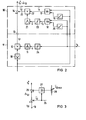
- a direct converter with a single-phase output is arranged on a three-phase network R, S, T and consists of the two antiparallel partial converters I, II.
- the output voltage u A and the output current i A are detected and fed to a control device 3, which determines a control voltage U St according to a predetermined current setpoint i A , which is fed to a control rate 4.
- This tax rate 4 is designed so that there is proportionality between the control voltage U st and the control angle ⁇ .
- a computing circuit 9 which simulates equation (1).
- This control circuit contains an absolute value generator (rectifier) 10 which is acted upon by an electrical variable corresponding to the output current i A.
- the actual value i be used; in the case of a sufficiently fast control device 3, however, as shown in FIG. 1, the corresponding desired value i A can also advantageously be used.
- a function generator 11 is provided which is supplied with the control voltage U st (in this case synonymous with the control angle ⁇ ) and whose output variable corresponds to cos ⁇ .
- the output variables of these two elements 10, 11 are applied to a multiplier 12, at the output 13 of which a theoretically determined variable for the fundamental oscillation reactive current i Q1 can be tapped according to equation (1).
- This value i Q1 can be supplied directly as a setpoint for the reactive current i B to be supplied in the control unit 8.
- the memories 5, 6 are not designed to compensate for the entire network perturbations of the direct converter. Rather, only the modulation power is to be compensated for, while the fundamental vibration reactive power remains uncompensated.
- the difference ⁇ i Q1 between the theoretical value i Q1 for the instantaneous reactive power current and the mean value is therefore used as the setpoint iB i Q1 of the fundamental oscillation reactive current is formed.
- the output 13 is followed by a differential element 14, which is supplied with the value i Q1 from the output 13 and with the opposite sign from the mean value i Q1 tapped at the output 13 via the smoothing element 15.
- This mean value circuit 14, 15 is designed for a large smoothing in order to minimize residual ripple of the mean value i Generate Q1 (time constant over several network periods). However, this requires a long response time when the mean value changes.
- a mean value circuit 16 'shown in FIG. 2 is therefore advantageously used, which is based on the consideration that the quantities i A and u A are temporally sinusoidally changing quantities, so that they are each in a right-angled coordinate system as the one component of an orbiting vector Length (of the amount) i A and u A can be understood.
- the calculation of the mean values i A and u A happens now by vector evaluation using vector analyzers 17, 18, each of which as a component has the input variables i A and u . are connected, while the other, perpendicular components are derived from these input variables by means of integrators 19, 20.
- this input variable can also be used for the arithmetic circuit 9', only the function generator 11 having a function generator 24 corresponding to the function generator 23 Transfer of the input voltage u A into the control angle f is connected upstream.
- the size .DELTA.i Q1 output supplying the mean value circuit 16, respectively. 16 'to add an addition point 26 to which the value for i Q1 tapped off via line 25 at the output of smoothing element 15 or multiplier 22 is correspondingly weighted. This weighting can take place via a threshold value limiter 27, the limiting threshold value of which can be set, for example, via a potentiometer 28.
- the active power also pulsates.
- This active power pulsation can be compensated if the compensator used is also designed for such compensations.
- the modulated active component of the mains current is applied analogously to equation (1)
- i W are used, which are formed in an averaging circuit 32 connected downstream of the multiplier 31 and, analogously to the averaging circuit 16 from FIG. 1, consists of a smoothing element 33 and a connection point 34.
- the arithmetic circuits 9 and 9 ' can also be used for direct converters with a multi-phase output.
- a computing circuit 9 a, 9 b and 9 c is provided for each phase output a, b and c, which in the case of FIG. 1 has the corresponding phase output current i Aa or i Ab or i Ac (or its setpoint i Aa or . i i Ab or Ac) and the control angle a and ⁇ ⁇ ⁇ b or c (or in the case of Figure 2 via a corresponding function converter 24 a and 2 4 b and 24 c, the p Phasenausgangss oltage U Aa bz w .
- each of these arithmetic circuits also contains an absolute value generator 10 a or 10 b or 10 c, an angular function generator 11 a, 11 b or 11 c and a multiplier 12 a or 12 b or 12 c.
- the output variables of the multipliers 12 a, 12 b, 12 c are combined at an addition point 40 to the theoretical value for the fundamental oscillation reactive current i Q1 .
- an average value circuit 16 analogous to FIG. 1 can also be connected downstream of the output 13 here. However, averaging can also be carried out here by vectorial evaluation of the input variables, as shown in FIG.
- To form the mean i A is provided with the vector analyzer 17 'to which the components of the output current vector i A are supplied in a right-angled coordinate system. Since the current vector i A is composed of the three phase currents i Aa ' i Ab and i Ac , the vector analyzer 17' is preceded by a coordinate converter 41.
- the mean ⁇ is also formed analogously to FIG.
- phase output voltage u Aa , u Ab , u Ac is converted via a coordinate converter into the two components of the voltage vector u A with respect to a right-angled coordinate system, in the vector analyzer 18 'the amount of the vector from the two components educated and this in a function generator 23 'into the control angle mean ⁇ being transformed. If instead of the phase output voltages u Aa , ... the corresponding control angles ⁇ a , ... or control voltages U St a, ...
- the control voltages or control angles can be switched by the corresponding inputs of the coordinate converter 22 upstream function converter 43 a , 43 b, 43 c are converted according to the proportionality between U Aa and ⁇ A , U Ab and d ⁇ b and U Ac and ⁇ c .
- the characteristic curves of the function formers 43 a, 43 b and 43 c on the one hand and of the function formers 23 'on the other hand are inverse to one another; these function formers are only shown in broken lines in FIG. 7, since it is shown that a simultaneous omission of these function formers practically does not lead to an error.
Abstract
Description
Die Erfindung betrifft ein Verfahren zur Minderung der Netzrückwirkungen eines an ein Drehstromnetz angeschlossenen netzgeführten Direktumrichters durch Aussteuerung eines an das Drehstromnetz angeschlossenen steuerbaren Blindleistungskompensators sowie eine Steuerschaltung zur Bildung des Sollwertes für die Aussteuerung des Blindleistungskompensators nach diesem Verfahren.The invention relates to a method for reducing the network perturbations of a mains-operated direct converter connected to a three-phase network by controlling a controllable reactive power compensator connected to the three-phase network and a control circuit for forming the setpoint for controlling the reactive power compensator according to this method.
Drehstromnetze, insbesondere schwache Netze, reagieren auf die von angeschlossenen Umrichtern aufgenommene Blindleistung häufig mit erheblichen Spannungsschwankungen, die an anderen Verbrauchern zu Flickererscheinungen oder bei Resonanzstellen der Netzimpedanz zu Spannungsverzerrungen führen können. Durch Kondensatoren oder Filterkreise kann eine mittlere Blindleistung kompensiert werden. Es können ans Netz auch induktive oder kapazitive Speicher mit Steuereinrichtungen (z.B. gesteuerten Gleichstromstellern) angeschlossen werden, die durch einen überlagerten Blindleistungsregelkreis angesteuert werden und in der Lage sind, Blindleistung entsprechend der Umrichter-Blindleistungsaufnahme ins Netz einzuspeisen. Eine derartige Blindleistungsregelung mit den zugehörigen Meßeinrichtungen ist jedoch verhältnismäßig aufwendig und wegen der Zeitkonstanten in der Regel nur schlecht geeignet, auch die periodischen Modulationen der Blindleistungsaufnahme zu kompensieren, die bei derartigen Umrichtern in der Regel auftreten.Three-phase networks, particularly weak networks, often react to the reactive power consumed by connected converters with considerable voltage fluctuations, which can lead to flicker phenomena at other consumers or to voltage distortions at resonance points of the network impedance. A medium reactive power can be compensated by capacitors or filter circuits. Inductive or capacitive storage devices with control devices (e.g. controlled direct current controllers) can also be connected to the network, which are controlled by a superimposed reactive power control circuit and are able to feed reactive power into the network in accordance with the converter reactive power consumption. Such reactive power control with the associated measuring devices is, however, relatively complex and, because of the time constants, is generally only poorly suited to compensating for the periodic modulations of the reactive power consumption which generally occur with such converters.
Es ist üblich, für Leistungsabschätzungen die arithmetischen Mittelwerte des Wirkstromes iW sowie des Blindstromes iQ während einer Halbperiode der Umrichter-Ausgangsfrequenz zu betrachten und daraus die konventionelle Scheinleistung zu bilden, die genauer als Grundschwingungsscheinleistung S1 zu bezeichnen ist. Für die Dimensionierung von elektrischen Einrichtungen ist jedoch die Rechtleistung maßgebend, die vom Effektivwert der modulierten Grundschwingung des Netzstromes während einer Halbperiode der Ausgangsfrequenz bestimmt ist und die stets um einen bestimmten Leistungsbetrag ("Modulationsleistung") größer ist als die Grundschwingungsscheinleistung. Bedingt durch das Umrichtverfahren ist die Blindleistungsaufnahme von Direktumrichtern stets mit einer vielfachen Frequenz der Direktumrichter-Ausgangsfrequenz moduliert. Die Folge ist eine Modulation des Netzstromes mit Oberschwingungs-und Unterschwingungsströmen. So erzeugt z.B. ein aus 6-pulsigen Teilumrichtern aufgebauter Direktumrichter mit Drehstromausgang wegen der genannten Blindleistungsmodulation neben dem netzfrequenten Blindstrom noch Seitenfrequenzen, die gegenüber der Netzfrequenz um das 6-fache Verhältnis von Ausgangsfrequenz zu Netzfrequenz verschoben sind. Bei Umrichtern mit einphasigem Ausgang ist sowohl die Wirkleistung als auch die Grundschwingungsblindleistung moduliert, so daß sich weitere Seitenfrequenzen ergeben. Das entsprechende Frequenzspektrum aus Seitenfrequenzen tritt auch für die weiteren von der Pulszahl der Umrichterschaltung abhängigen Oberschwingungen des Netzstromes auf, wobei jedoch meist die von diesen Oberschwingungen hervorgerufenen Netzrückwirkungen gering sind.It is customary for power estimates to consider the arithmetic mean values of the active current i W and the reactive current i Q during a half period of the converter output frequency and to use them to form the conventional apparent power, which is more precisely to be referred to as the basic vibration apparent power S1. For the dimensioning of electrical devices, however, the legal power is decisive, which is determined by the effective value of the modulated fundamental oscillation of the mains current during a half period of the output frequency and which is always a certain amount of power ("modulation power") greater than the basic vibration apparent power. Due to the conversion process, the reactive power consumption of direct converters is always modulated with a multiple frequency of the direct converter output frequency. The result is a modulation of the mains current with harmonic and undershoot currents. For example, a direct converter with a three-phase output consisting of 6-pulse partial converters generates side frequencies due to the reactive power modulation mentioned, in addition to the line frequency reactive current, which are shifted 6 times the ratio of the output frequency to the line frequency. In converters with a single-phase output, both the active power and the fundamental oscillation reactive power are modulated, so that there are further side frequencies. The corresponding frequency spectrum from side frequencies also occurs for the further harmonics of the mains current which are dependent on the number of pulses in the converter circuit, although the mains feedback effects caused by these harmonics are usually low.
Der Erfindung liegt die Aufgabe zugrunde, die Grundschwingungsblindleistung und/oder deren Modulation ohne eine Regelung der Blindleistung und die zugehörigen Meßeinrichtungen zu kompensieren. Dadurch fallen auch die Zeitkonstanten der üblichen Blindleistungsregelungen weg, so daß die Kompensation schneller vorgenommen werden kann.The invention is based on the object of compensating the fundamental reactive power and / or its modulation without regulating the reactive power and the associated measuring devices. This also eliminates the time constants of the usual reactive power controls, so that the compensation can be carried out more quickly.
Dies wird erreicht durch eine Aussteuerung eines an das Drehstromnetz angeschlossenen steuerbaren Blindleistungskompensators, bei der gemäß der Erfindung der Sollwert für die Steuerung des vom Blindleistungskompensator zu liefernden Blindstromes aus dem Produkt vom Betrag des Direktumrichter-Ausgangsstromes und einer vorgegebenen Funktion des Direktumrichter-Steuerwinkels ψ gebildet wird, und zwar unabhängig vom Ist-Wert des netzseitigen Blindstromes selbst. Der Direktumrichter-Steuerwinkel kann dabei aus der Direktumrichter-Ausgangsspannung oder aus der Steuerspannung des Direktumrichters abgeleitet werden, z.B. kann bei entsprechender Proportionalität zwischen Steuerspannung und Steuerwinkel direkt die Steuerspannung als Steuerwinkel bzw. als die in das Produkt eingehende Funktion des Steuerwinkels verwendet werden.This is achieved by modulating a controllable reactive power compensator connected to the three-phase network, in which, according to the invention, the setpoint for controlling the reactive current to be supplied by the reactive power compensator is formed from the product of the amount of the direct converter output current and a predetermined function of the direct converter control angle ψ , regardless of the actual value of the line-side reactive current itself. The direct converter control angle can be derived from the direct converter output voltage or from the control voltage of the direct converter, for example With appropriate proportionality between the control voltage and the control angle, the control voltage can be used directly as the control angle or as the function of the control angle that is included in the product.
Der Erfindung liegt dabei die Erkenntnis zugrunde, daß es für die Aussteuerung des ins Netz einzuspeisenden, kompensierenden Blindstromes genügt, einen Sollwert iB anzugeben, der aufgrund theoretischer Betrachtungen über den Grundschwingungsblindstrom und idealisierender Annahmen aus der Formel
Für netzgeführte Direktumrichter besteht ein Zusammenhang zwischen der Umrichterausgangsspannung uA, der ideellen Lehrlaufgleichspannung Udi 0 und dem Steuerwinkel ψ, so daß sich ψ aus
In der Regel ist für die Steuerung des Direktumrichters ein Regelkreis vorgesehen, bei dem die Steuerspannung Ust der Direktumrichter-Ventile aus den Istwerten des. Ausgangsstromes iA bzw. der Ausgangsspannung UA und einem Strom-Sollwert iA gebildet wird. Die Eingangsgrößen für die Gleichung (1) liegen also in Form entsprechender Sollwerte iA und y (bzw. Ust) bereits vor. Jedoch kann es vorteilhaft sein, einen der Sollwerte oder beide Sollwerte durch die entsprechenden Istwerte iA und UA unter Zuhilfenahme von Gleichung (2) zu verwenden.As a rule, a control circuit is provided for controlling the direct converter, in which the control voltage U st of the direct converter valves is formed from the actual values of the output current i A or the output voltage U A and a current setpoint i A. The input variables for equation (1) are therefore already in the form of corresponding setpoints i A and y (or U st ). However, it can be advantageous to use one of the target values or both target values by means of the corresponding actual values i A and U A with the aid of equation (2).
. Nach der Erfindung kann die Bildung des Sollwertes für die Aussteuerung des Blindleistungskompensators vorteilhaft durch eine Steuerschaltung mit einem vom Istwert oder Sollwert des Direktumrichter-Ausgangsstromes beaufschlagten Betragsbildner, einem von einer dem Direktumrichter-Steuerwinkel ψ entsprechenden Größe beaufschlagten Funktionsbildner und einem von den Ausgangsgrößen des Betragsbildners und des Funktionsbildners beaufschlagten Multiplizierglied berechnet werden. Diese Steuerschaltung stellt somit eine Rechenschaltung für die Gleichung (1) dar und ihre Ausgangsgröße kann direkt oder über eine nachgeordnete Mittelwertschaltung, die noch erläutert werden wird, als Stellgröße für den zu liefernden Kompensationsblindstrom iB verwendet werden.. According to the invention, the formation of the setpoint for the modulation of the reactive power compensator can advantageously be carried out by a control circuit with an amount generator acted upon by the actual value or setpoint of the direct converter output current, a function generator acted on by a variable corresponding to the direct converter control angle ψ and one of the output variables of the absolute generator and multiplier applied to the function generator. This control circuit thus represents a computing circuit for equation (1) and its output variable can be used as a manipulated variable for the compensation reactive current i B to be supplied, either directly or via a subordinate mean value circuit, which will be explained below.
Sofern anstelle von ψ in Gleichung (1) die Ausgangsspannung uA entsprechend Gleichung (2) verwendet wird, ist dem Funktionsbildner ein zweiter Funktidnsbildner vorzuschalten, dem die Ausgangsspannung des Direktumrichters aufgeschaltet ist und dessen Kennlinie den Zusammenhang zwischen Steuerwinkel und Ausgangsspannung entspricht.If the output voltage u A according to equation (2) is used instead of Gleich in equation (1), the function generator must be preceded by a second function generator, to which the output voltage of the direct converter is connected and whose characteristic curve corresponds to the relationship between the control angle and the output voltage.
Häufig tritt der Fall auf, daß die vom mittleren Blindstrom (gemittelt über eine Periode der Ausgangsfrequenz) hervorgerufene Netzrückwirkung für das Netz selbst und für andere am Netz angeschlossene Verbraucher nicht kritisch ist, oder daß die Grundschwingungsblindleistung nicht in voller Höhe kompensiert zu werden braucht oder aus wirtschaftlichen Gründen kompensiert werden soll, jedoch die von der Modulation der Blindleistung hervorgerufenen Seitenfrequenzen der Rückwirkungsfrequenzen unterdrückt werden sollen. In diesem Fall wird vorteilhaft als Sollwert iB nicht der volle entsprechend Gleichung (1) berechnete Wert des vom Direktumrichter aufgenommenen Blindstromes verwendet, sondern nur dessen Abweichung ΔiQ1 von einem entsprechenden Mittelwert
Obwohl eine volle Kompensation der Blindleistung vor allem bei Umrichtern mit Drehstromausgang häufig nicht wirtschaftlich möglich ist, kann jedoch eine vollkommene Kompensation der Modulationsleistung wünschenswert sein. In diesem Fall wird für die Bildung des Sollwertes i*B zu der soeben berechneten Differenz ΔiQ1, die zur vollkommenen Kompensation der Modulationsleistung führt, der Wert iQ1 des Produkt-Mittelwertes selbst mit einer entsprechenden Gewichtung addiert. Diese Gewichtung kann z.B. darin bestehen, daß für niedere Werte für
Bei Direktumrichtern mit einphasigen Ausgang pulsiert auch die Wirkleistung mit doppelter Ausgangsfrequenz. In diesem Fall ist es vorteilhaft, als steuerbaren Blindleistungskompensator einen Kompensator zu verwenden, der auch Leistungspulsationen kompensieren kann, z.B. eine drehfelderregte Schleifringläufermaschine, die ein Schwungrad antreibt. Zur Steuerung des vom Kompensator zu liefernden Wirkstromes wird dabei vorteilhaft ein Rechenwert iW verwendet, der proportional dem Produkt iA·sin Ψ berechnet wird. Der Sollwert für den Wirkleistungsmodulations-Kompensationsstrom wird dann als Differenz zwischen diesem Rechenwert iW und einem entsprechenden Mittelwert
Diese und weitere,vorteilhafte Ausführungsformen der Erfindung sind in den Ansprüchen näher gekennzeichnet.These and further advantageous embodiments of the invention are characterized in more detail in the claims.
Anhand von mehreren Ausführungsbeispielen und 7 Figuren wird die Erfindung näher erläutert. Es zeigen:
- - Figur 1 eine Anordnung mit einem an ein dreiphasiges Drehstromnetz angeschlossenen Direktumrichter mit einphasigen Ausgang, einer steuerbaren Kompensationseinrichtung und einer aus einer Rechenschaltung und einer Mittelwertschaltung bestehenden Steuerschaltung zur Bildung des Sollwertes für die Aussteuerung des Blindleistungskompensators mit den Eingangsgrößen iA und USt'
- - Figur 2 eine Rechenschaltung und eine Mittelwertschaltung mit den Istwerten iA und uA als Eingangsgrößen,
- -
Figur 3 eine Schaltung zur gewichteten Aufschaltung voni Q1 zur Differenz iQ1, - - Figur 4 und 5 Steuerschaltungen für die Kompensation von Wirkleistungsmodulationen bei Direktumrichtern mit einphasigem Ausgang,
- -
Figur 6 eine Ausführung der Steuerschaltung für den Fall, daß ans Netz ein Direktumrichter mit dreiphasigem Ausgang angeschlossen ist, und - -
Figur 7 eine Variante der Mittelwertschaltung bei einer Steuerschaltung nachFigur 6.
- - Figure 1 shows an arrangement with a direct converter connected to a three-phase three-phase network with a single-phase output, a controllable compensation device and a control circuit consisting of a computing circuit and a mean value circuit for forming the setpoint for the modulation of the reactive power compensator with the input variables i A and U St '
- FIG. 2 shows an arithmetic circuit and an average circuit with the actual values i A and u A as input variables,
- - Figure 3 shows a circuit for the weighted connection of
i Q1 to the difference i Q1 , - FIGS. 4 and 5 control circuits for the compensation of active power modulations in direct converters with a single-phase output,
- - Figure 6 shows an embodiment of the control circuit in the event that a direct converter with a three-phase output is connected to the network, and
- FIG. 7 shows a variant of the mean value switching in a control circuit according to FIG. 6.
Gemäß Figur 1 ist an ein Drehstromnetz R, S, T ein Direktumrichter mit einphasigem Ausgang angeordnet, der aus den beiden antiparallelen Teilstromrichtern I, II besteht. An den Umrichterausgängen 1, 2 wird die Ausgangsspannung uA und der Ausgangsstrom iA erfaßt und einer Regeleinrichtung 3 zugeführt, die entsprechend einem vorgegebenen Stromsollwert iA eine Steuerspannung USt ermittelt, die einem Steuersatz 4 zugeführt wird. Dieser Steuersatz 4 ist so ausgelegt, daß Proportionalität zwischen der Steuerspannung Ust und dem Steuerwinkell Ψ besteht. Von den Ausgangsimpulsen des Steuersatzes 4 werden die Ventile des Stromrichters I mit einem Zündwinkel αI = π/2 -Ψ bzw. bei Vorzeichenumkehr die Ventile des Stromrichters II mit dem Zündwinkel αII = Ψ + π/2 angesteuert.According to FIG. 1, a direct converter with a single-phase output is arranged on a three-phase network R, S, T and consists of the two antiparallel partial converters I, II. At the converter outputs 1, 2, the output voltage u A and the output current i A are detected and fed to a
Zwischen die Netzphasen R, S, T sind Speicher aus Induktivitäten 5 und Kapazitäten 6 angeordnet, die über induktiv belastete Gleichstromsteller 7 zur Kompensation des vom Direktumrichter I, II aufgenommenen Blindstromes in das Netz entladen werden können. Zur Steuerung dieses Blindstromkompensators 5, 6, 7 dient eine Blindstromsteuereinrichtung 8, die die Zündimpulse für die Ventile der Gleichstromsteller 7 liefert.Arranged between the network phases R, S, T are stores of
Zur Bildung des Sollwertes iBt auf den die Blindstromsteuereinrichtung 8 den vom Blindstromkompensator 5, 6, 7 einzuspeisenden Blindstrom steuert, ist eine Rechenschaltung 9 vorgesehen, die die Gleichung (1) nachbildet. Diese Steuerschaltung enthält einen Betragsbildner (Gleichrichter) 10, der von einer dem Ausgangsstrom iA entsprechenden elektrischen Größe beaufschlagt ist. Dazu kann der am Ausgang 1 erfaßte Istwert i. verwendet werden; bei einer hinreichend schnellen Regeleinrichtung 3 kann jedoch, wie in Figur 1 dargestellt ist, vorteilhaft auch der entsprechende Sollwert iA verwendet werden. Ferner ist ein Funktionsgeber 11 vorgesehen, der mit der Steuerspannung Ust (in diesem Fall gleichbedeutend mit dem Steuerwinkel Ψ) beaufschlagt ist und dessen Ausgangsgröße cos Ψ entspricht. Die Ausgangsgrößen dieser beiden Elemente 10, 11 werden einem Multiplizierglied 12 aufgeschaltet, an dessen Ausgang 13 entsprechend Gleichung (1) eine theoretisch bestimmte Größe für den Grundschwingungsblindstrom iQ1 abgegriffen werden kann.In order to form the setpoint i Bt on which the reactive
Dieser Wert iQ1 kann direkt als Sollwert für den zu liefernden Blindstrom iB im Steuersatz 8 zugeführt werden. Beim Ausführungsbeispiel nach Figur 1 sind die Speicher 5, 6 jedoch nicht zur Kompensation der gesamten Netzrückwirkungen des Direktumrichters ausgelegt, vielmehr soll lediglich die Modulationsleistung kompensiert werden, während die Grundschwingungsblindleistung unkompensiert bleibt. Daher wird als Sollwert iB die Differenz ΔiQ1 zwischen dem theoretischen Wert iQ1 für den momentanen Blindleistungsstrom und dem Mittelwert
Vorteilhaft wird daher eine in Figur 2 gezeigte Mittelwertschaltung 16' verwendet, die auf der Überlegung basiert, daß die Größen iA und uA zeitlich sich sinusartig ändernde Größen sind, so daß sie jeweils in einem rechtwinkeligen Koordinatensystem als die eine Komponente eines umlaufenden Vektors der Länge (des Betrages)
Die Berechnung der Mittelwerte
Entsprechend dem in Figur 2 gezeigten Fall, daß als Eingangsgröße für die Mittelwertschaltung 16' die Direktumrichter-Ausgangsspannung uA verwendet wird, kann diese Eingangsgröße auch für die Rechenschaltung 9' verwendet werden, wobei lediglich dem Funktionsbildner 11 ein dem Funktionsbildner 23 entsprechender Funktionsbildner 24 zur Überführung der Eingangsspannung uA in den Steuerwinkel f vorgeschaltet wird.Corresponding to the case shown in FIG. 2 that the direct converter output voltage u A is used as the input variable for the mean value circuit 16 ', this input variable can also be used for the arithmetic circuit 9', only the
Soll nun abweichend von Figur 1 nicht die gesamte mittlere Grundschwingungsblindleistung unkompensiert bleiben, sondern diese mittlere Grundschwingungsblindleistung bis zu einem Maximalwert kompensiert und lediglich diesen Maximalwert übersteigende Blindleistungen unkompensiert bleiben, so ist entsprechend Figur 3 vorgesehen, dem die Größe ΔiQ1 liefernden Ausgang der Mittelwertschaltung 16 ,bzw. 16' eine Additionsstelle 26 nachzuschalten, der der über die Leitung 25 am Ausgang des Glättungsgliedes 15 bzw. Multipliziergliedes 22 abgegriffene Wert für iQ1 entsprechend gewichtet aufgeschaltet wird. Diese Gewichtung kann über einen Schwellwertbegrenzer 27 geschehen, dessen begrenzender Schwellwert z.B. über ein Potentiometer 28 einstellbar ist.Will now not remain deviating from Figure 1, the overall average fundamental wave reactive power uncompensated, but up to a maximum value compensates for this average fundamental reactive power and only this maximum value exceeding reactive powers remain uncompensated, it is provided according to FIG 3, the size .DELTA.i Q1 output supplying the
Wie bereits erwähnt wurde, pulsiert bei einem Direktumrichter mit einphasigem Ausgang, wie er in Figur 1 gezeigt ist, auch die Wirkleistung. Diese Wirkleistungspulsation kann kompensiert werden, wenn der verwendete Kompensator auch für derartige Kompensationen ausgelegt ist. Für die modulierte Wirkkomponente des Netzstromes wird gemäß der Erfindung analog zu Gleichung (1) angesetzt![]()
![]()
wobei bei Verwendung geeigneter Steuersätze wiederum proportional USt und uA proportional sin Ψ zu setzen ist. Zur Nachbildung der Gleichung (3) kann daher wiederum neben dem Umrichterausgangsstrom iA bzw. dessen Sollwert iA von der Spannung uA bzw. über einen vorgeschalteten Winkelfunktionsgeber 30 (Figur 4)von der Steuerspannung USt ausgegangen werden. Um die pulsierende rechnerische Wirkstromkomponente des Netzstromes entsprechend der Gleichung (3) nachzubilden, ist es dann lediglich erforderlich, die Größen iA und uA einem Multiplizierglied 31 zuzuführen. Als Sollwert für die Wirkstromaussteuerung kann nun wiederum die rechnerisch nachgebildete Pulsation ΔiW = iW -
Die Rechenschaltungen 9 bzw. 9' lassen sich auch für Direktumrichter mit mehrphasigem Ausgang verwenden. In Figur 6 ist eine derartige Schaltung für einen dreiphasigen Direktumrichter angegeben. Dabei ist für jeden Phasenausgang a, b und c jeweils eine Rechenschaltung 9 a, 9 b bzw. 9 c vorgesehen, der im Fall von Figur 1 der entsprechende Phasenausgangsstrom iAa bzw. iAb bzw. iAc (oder deren Sollwert iAa bzw. iAb bzw. i Ac) und der Steuerwinkel Ψa bzw. Ψb bzw. Ψc (oder im Fall der Figur 2 über einen entsprechenden Funktionswandler 24 a bzw. 24 b bzw. 24 c die Phasenausgangsspannung UAa bzw. UAb bzw. UAc) zugeführt werden. Jede dieser Rechenschaltungen enthält auch in diesem Fall jeweils einen Betragsbildner 10 a bzw. 10 b bzw. 10 c, einen Winkelfunktionsbildner 11 a, 11 b bzw. 11 c und ein Multiplizierglied 12 a bzw. 12 b bzw. 12 c. Die Ausgangsgrößen der Multiplizierglieder 12 a, 12 b, 12 c werden an einer Additionsstelle 40 zum theoretischen Wert für den Grundschwingungsblindstrom iQ1 zusammengesetzt.The
Soll dieser Wert iQ1 nicht als Sollwert für die Kompensation der gesamten Grundschwingungsblindleistung, sondern nur für die Kompensation der Modulationsleistung verwendet werden, so kann dem Ausgang 13 auch hier eine Mittelwertschaltung 16 analog zu Figur 1 nachgeschaltet sein. Es läßt sich aber auch hier eine Mittelwertbildung durch vektorielle Auswertung der Eingangsgrößen durchführen, wie in Figur 7 gezeigt ist. Zur Bildung des Mittelwertes
Da ferner häufig für die Regelung der Direktumrichter-Aussteuerung bereits Koordinatenwandler 41, 42 und Vektoranalysatoren 17', 18' zur Bildung von iA und uA vorgesehen sind, ergibt sich hiermit die Möglichkeit, ohne eine Blindleistungsregelung mit zugehörigen Meßeinrichtungen die Grundschwingungsblindleistung und ihre Modulation mit geringem Aufwand zu kompensieren.Furthermore, since coordinate
Claims (12)
Applications Claiming Priority (2)
| Application Number | Priority Date | Filing Date | Title |
|---|---|---|---|
| DE19803002373 DE3002373A1 (en) | 1980-01-23 | 1980-01-23 | METHOD FOR REDUCING THE NET REACTIVE EFFECTS OF A NETWORKED DIRECT CONVERTER AND CONTROL SWITCH THEREFOR |
| DE3002373 | 1980-01-23 |
Publications (3)
| Publication Number | Publication Date |
|---|---|
| EP0033842A2 true EP0033842A2 (en) | 1981-08-19 |
| EP0033842A3 EP0033842A3 (en) | 1982-05-12 |
| EP0033842B1 EP0033842B1 (en) | 1984-10-24 |
Family
ID=6092772
Family Applications (1)
| Application Number | Title | Priority Date | Filing Date |
|---|---|---|---|
| EP81100123A Expired EP0033842B1 (en) | 1980-01-23 | 1981-01-09 | Method for mains feedback of a line commutated direct converter and control circuit therefor |
Country Status (4)
| Country | Link |
|---|---|
| EP (1) | EP0033842B1 (en) |
| JP (1) | JPS56110116A (en) |
| DE (2) | DE3002373A1 (en) |
| NO (1) | NO158769C (en) |
Cited By (8)
| Publication number | Priority date | Publication date | Assignee | Title |
|---|---|---|---|---|
| EP0111088A1 (en) * | 1982-11-03 | 1984-06-20 | BBC Brown Boveri AG | Currant rectifier |
| GB2167582A (en) * | 1984-11-23 | 1986-05-29 | Gen Electric Co Plc | Reactive power compensating circuit |
| GB2294165A (en) * | 1994-10-11 | 1996-04-17 | Lumonics Ltd | Power supply for providing a dc supply from a multiphase ac source |
| WO1996024186A1 (en) * | 1995-02-01 | 1996-08-08 | Westinghouse Electric Corporation | Dynamic power and voltage regulator for an ac transmission line |
| WO2003034566A1 (en) * | 2001-10-17 | 2003-04-24 | Hatch Ltd. | Control system and method for voltage stabilization |
| US6603795B2 (en) | 2001-02-08 | 2003-08-05 | Hatch Associates Ltd. | Power control system for AC electric arc furnace |
| US7212562B2 (en) | 2004-09-01 | 2007-05-01 | Hatch Ltd. | System and method for controlling total electrical power across multiple furnaces using electrode positioning |
| DE102012209369A1 (en) * | 2012-06-04 | 2013-12-05 | Siemens Aktiengesellschaft | Control device for eliminating disturbances in the network |
Families Citing this family (5)
| Publication number | Priority date | Publication date | Assignee | Title |
|---|---|---|---|---|
| DE3708468A1 (en) * | 1986-03-17 | 1987-09-24 | Siemens Ag | Method and device for compensating for harmonic loads and/or a reactive load in a supply network |
| JPH0833786B2 (en) * | 1986-07-21 | 1996-03-29 | サンケン電気株式会社 | Reactive power regulator |
| JPH0211466U (en) * | 1988-07-07 | 1990-01-24 | ||
| JPH02135511A (en) * | 1988-11-16 | 1990-05-24 | Toshiba Corp | Reactive power compensating device |
| DE4327894A1 (en) * | 1993-08-19 | 1995-02-23 | Abb Management Ag | Method for stabilizing a power grid against fluctuations in reactive load and reactive power compensation device |
Citations (3)
| Publication number | Priority date | Publication date | Assignee | Title |
|---|---|---|---|---|
| CH502011A (en) * | 1968-03-23 | 1971-01-15 | Licentia Gmbh | Arrangement for stabilizing the voltage of a supply network |
| DE2201800A1 (en) * | 1971-01-18 | 1972-08-03 | Allmaenna Svenska Elek Ska Ab | Arrangement for generating reactive power |
| DE2244757B2 (en) * | 1972-09-08 | 1976-01-29 | Licentia Patent-Verwaltungs-Gmbh, 6000 Frankfurt | PROCESS FOR MAINTAINING THE SPEED OF A INVERTER CONTAINING A VIBRANT CIRCUIT INVERTER |
-
1980
- 1980-01-23 DE DE19803002373 patent/DE3002373A1/en not_active Withdrawn
-
1981
- 1981-01-09 DE DE8181100123T patent/DE3166740D1/en not_active Expired
- 1981-01-09 EP EP81100123A patent/EP0033842B1/en not_active Expired
- 1981-01-21 NO NO810186A patent/NO158769C/en unknown
- 1981-01-22 JP JP857381A patent/JPS56110116A/en active Granted
Patent Citations (3)
| Publication number | Priority date | Publication date | Assignee | Title |
|---|---|---|---|---|
| CH502011A (en) * | 1968-03-23 | 1971-01-15 | Licentia Gmbh | Arrangement for stabilizing the voltage of a supply network |
| DE2201800A1 (en) * | 1971-01-18 | 1972-08-03 | Allmaenna Svenska Elek Ska Ab | Arrangement for generating reactive power |
| DE2244757B2 (en) * | 1972-09-08 | 1976-01-29 | Licentia Patent-Verwaltungs-Gmbh, 6000 Frankfurt | PROCESS FOR MAINTAINING THE SPEED OF A INVERTER CONTAINING A VIBRANT CIRCUIT INVERTER |
Cited By (15)
| Publication number | Priority date | Publication date | Assignee | Title |
|---|---|---|---|---|
| EP0111088A1 (en) * | 1982-11-03 | 1984-06-20 | BBC Brown Boveri AG | Currant rectifier |
| GB2167582A (en) * | 1984-11-23 | 1986-05-29 | Gen Electric Co Plc | Reactive power compensating circuit |
| GB2294165A (en) * | 1994-10-11 | 1996-04-17 | Lumonics Ltd | Power supply for providing a dc supply from a multiphase ac source |
| WO1996024186A1 (en) * | 1995-02-01 | 1996-08-08 | Westinghouse Electric Corporation | Dynamic power and voltage regulator for an ac transmission line |
| US5610501A (en) * | 1995-02-01 | 1997-03-11 | Westinghouse Electric Corporation | Dynamic power and voltage regulator for an ac transmission line |
| US6603795B2 (en) | 2001-02-08 | 2003-08-05 | Hatch Associates Ltd. | Power control system for AC electric arc furnace |
| US6573691B2 (en) | 2001-10-17 | 2003-06-03 | Hatch Associates Ltd. | Control system and method for voltage stabilization in electric power system |
| WO2003034566A1 (en) * | 2001-10-17 | 2003-04-24 | Hatch Ltd. | Control system and method for voltage stabilization |
| EP1863146A1 (en) | 2001-10-17 | 2007-12-05 | Hatch Ltd. | Control system and method for voltage stabilization |
| CN100392938C (en) * | 2001-10-17 | 2008-06-04 | 哈茨有限公司 | Control system and method for voltage stabilization |
| US7212562B2 (en) | 2004-09-01 | 2007-05-01 | Hatch Ltd. | System and method for controlling total electrical power across multiple furnaces using electrode positioning |
| US7212561B2 (en) | 2004-09-01 | 2007-05-01 | Hatch Ltd. | System and method for controlling electrical power across multiple furnaces using variable reactors |
| US7257146B2 (en) | 2004-09-01 | 2007-08-14 | Hatch Ltd. | System and method for controlling power across multiple electrodes in a furnace |
| DE102012209369A1 (en) * | 2012-06-04 | 2013-12-05 | Siemens Aktiengesellschaft | Control device for eliminating disturbances in the network |
| US9356544B2 (en) | 2012-06-04 | 2016-05-31 | Siemens Aktiengesellschaft | Control device for eliminating malfunctions in a network |
Also Published As
| Publication number | Publication date |
|---|---|
| JPS56110116A (en) | 1981-09-01 |
| DE3002373A1 (en) | 1981-07-30 |
| DE3166740D1 (en) | 1984-11-29 |
| JPS6242470B2 (en) | 1987-09-08 |
| NO158769B (en) | 1988-07-18 |
| EP0033842A3 (en) | 1982-05-12 |
| EP0033842B1 (en) | 1984-10-24 |
| NO158769C (en) | 1988-10-26 |
| NO810186L (en) | 1981-07-24 |
Similar Documents
| Publication | Publication Date | Title |
|---|---|---|
| EP0144556B1 (en) | Reactive power compensator for compensating a reactive current component in an ac network | |
| DE2415398C3 (en) | Circuit arrangement with a number of converters, in particular direct converters in star connection | |
| DE2234681A1 (en) | PROCEDURE AND CIRCUIT ARRANGEMENT FOR REDUCING THE TORQUE RIPPLY OF A ROTATING FIELD MACHINE | |
| EP0033842B1 (en) | Method for mains feedback of a line commutated direct converter and control circuit therefor | |
| EP0800265B1 (en) | Process and apparatus for direct torque control of an induction machine | |
| DE69936505T2 (en) | CONTROL DEVICE FOR AN INDUCTION MOTOR | |
| DE3423333A1 (en) | CONTROL CIRCUIT AND METHOD FOR PROTECTING THE CONTROLLED RECTIFIERS OF A RECTIFIER | |
| EP1012946A1 (en) | Method and device for improving the quality of voltage of a secondary supply unit | |
| DE3423334A1 (en) | CONTROL CIRCUIT AND METHOD FOR A STATIC POWERED GENERATOR | |
| DE3319089C2 (en) | ||
| DE102009000600A1 (en) | Systems and methods of a single phase full bridge boost converter | |
| DE3429116C2 (en) | ||
| DE2217023C3 (en) | Feed circuit for a direct current consumer fed by a single or multi-phase alternating current source | |
| EP0570602B1 (en) | Three-phase machine regulation method with high quality dynamical determination of its statorvoltages in the electrical steady state | |
| EP0494137B1 (en) | Process and device for the optimum operation of a pulse converter connected to a power supply | |
| DE19734722C2 (en) | Method and device for improving the power quality of a superimposed network | |
| EP0315871A1 (en) | Process and device for the control of a current rectifier in an asymmetric network | |
| CH616785A5 (en) | Method for controlling the motor current of a converter-supplied three-phase motor | |
| DE686021C (en) | Device for superimposing alternating current power distribution networks with low currents of non-network frequency | |
| DE3203257A1 (en) | DEVICE FOR DETERMINING THE COMMON FREQUENCY OF TWO INDEPENDENTLY VARIABLE ALTERNATIVES, ESPECIALLY IN A TURNTABLE MACHINE | |
| EP0097958B1 (en) | Method and device for suppressing parasite values contained in an output valves system of a control device and in a direct cyclo-converter with three-phase current output | |
| DE19519759C2 (en) | Power converter | |
| DE4327162C1 (en) | Mains reactive power compensation for inverter-fed sync machine | |
| DE3138103C2 (en) | ||
| DE1918561C3 (en) | Power supply system for supplying a consumer with constant voltage direct current |
Legal Events
| Date | Code | Title | Description |
|---|---|---|---|
| PUAI | Public reference made under article 153(3) epc to a published international application that has entered the european phase |
Free format text: ORIGINAL CODE: 0009012 |
|
| AK | Designated contracting states |
Designated state(s): BE CH DE FR GB IT NL SE |
|
| 17P | Request for examination filed |
Effective date: 19811028 |
|
| PUAL | Search report despatched |
Free format text: ORIGINAL CODE: 0009013 |
|
| AK | Designated contracting states |
Designated state(s): BE CH DE FR GB IT NL SE |
|
| RHK1 | Main classification (correction) |
Ipc: H02J 3/18 |
|
| ITF | It: translation for a ep patent filed |
Owner name: STUDIO JAUMANN |
|
| GRAA | (expected) grant |
Free format text: ORIGINAL CODE: 0009210 |
|
| AK | Designated contracting states |
Designated state(s): BE CH DE FR GB IT LI NL SE |
|
| REF | Corresponds to: |
Ref document number: 3166740 Country of ref document: DE Date of ref document: 19841129 |
|
| ET | Fr: translation filed | ||
| PGFP | Annual fee paid to national office [announced via postgrant information from national office to epo] |
Ref country code: DE Payment date: 19850328 Year of fee payment: 5 |
|
| PLBI | Opposition filed |
Free format text: ORIGINAL CODE: 0009260 |
|
| 26 | Opposition filed |
Opponent name: AEG-TELEFUNKEN AKTIENGESELLSCHAFT, BERLIN UND FRAN Effective date: 19850712 |
|
| NLR1 | Nl: opposition has been filed with the epo |
Opponent name: AEG AKTIENGESELLSCHAFT |
|
| PLBN | Opposition rejected |
Free format text: ORIGINAL CODE: 0009273 |
|
| STAA | Information on the status of an ep patent application or granted ep patent |
Free format text: STATUS: OPPOSITION REJECTED |
|
| 27O | Opposition rejected |
Effective date: 19860324 |
|
| NLR2 | Nl: decision of opposition | ||
| PGFP | Annual fee paid to national office [announced via postgrant information from national office to epo] |
Ref country code: GB Payment date: 19890109 Year of fee payment: 9 |
|
| PGFP | Annual fee paid to national office [announced via postgrant information from national office to epo] |
Ref country code: SE Payment date: 19890118 Year of fee payment: 9 |
|
| PGFP | Annual fee paid to national office [announced via postgrant information from national office to epo] |
Ref country code: BE Payment date: 19890125 Year of fee payment: 9 |
|
| PGFP | Annual fee paid to national office [announced via postgrant information from national office to epo] |
Ref country code: FR Payment date: 19890126 Year of fee payment: 9 |
|
| ITTA | It: last paid annual fee | ||
| PG25 | Lapsed in a contracting state [announced via postgrant information from national office to epo] |
Ref country code: LI Effective date: 19890131 Ref country code: CH Effective date: 19890131 |
|
| PGFP | Annual fee paid to national office [announced via postgrant information from national office to epo] |
Ref country code: NL Payment date: 19890131 Year of fee payment: 11 |
|
| REG | Reference to a national code |
Ref country code: CH Ref legal event code: PL |
|
| PG25 | Lapsed in a contracting state [announced via postgrant information from national office to epo] |
Ref country code: DE Effective date: 19891003 |
|
| PG25 | Lapsed in a contracting state [announced via postgrant information from national office to epo] |
Ref country code: GB Effective date: 19900109 |
|
| PG25 | Lapsed in a contracting state [announced via postgrant information from national office to epo] |
Ref country code: SE Effective date: 19900110 |
|
| PG25 | Lapsed in a contracting state [announced via postgrant information from national office to epo] |
Ref country code: BE Effective date: 19900131 |
|
| BERE | Be: lapsed |
Owner name: SIEMENS A.G. BERLIN UND MUNCHEN Effective date: 19900131 |
|
| PG25 | Lapsed in a contracting state [announced via postgrant information from national office to epo] |
Ref country code: NL Effective date: 19900801 |
|
| GBPC | Gb: european patent ceased through non-payment of renewal fee | ||
| NLV4 | Nl: lapsed or anulled due to non-payment of the annual fee | ||
| PG25 | Lapsed in a contracting state [announced via postgrant information from national office to epo] |
Ref country code: FR Effective date: 19900928 |
|
| REG | Reference to a national code |
Ref country code: FR Ref legal event code: ST |
|
| EUG | Se: european patent has lapsed |
Ref document number: 81100123.9 Effective date: 19901106 |