EP0040689A1 - Control and precontrol device for switching on and switching off operations and for condition ranges - Google Patents
Control and precontrol device for switching on and switching off operations and for condition ranges Download PDFInfo
- Publication number
- EP0040689A1 EP0040689A1 EP81102705A EP81102705A EP0040689A1 EP 0040689 A1 EP0040689 A1 EP 0040689A1 EP 81102705 A EP81102705 A EP 81102705A EP 81102705 A EP81102705 A EP 81102705A EP 0040689 A1 EP0040689 A1 EP 0040689A1
- Authority
- EP
- European Patent Office
- Prior art keywords
- arrangement according
- dcu
- control units
- decentralized control
- unit
- Prior art date
- Legal status (The legal status is an assumption and is not a legal conclusion. Google has not performed a legal analysis and makes no representation as to the accuracy of the status listed.)
- Withdrawn
Links
Images

Classifications
-
- G—PHYSICS
- G05—CONTROLLING; REGULATING
- G05B—CONTROL OR REGULATING SYSTEMS IN GENERAL; FUNCTIONAL ELEMENTS OF SUCH SYSTEMS; MONITORING OR TESTING ARRANGEMENTS FOR SUCH SYSTEMS OR ELEMENTS
- G05B19/00—Programme-control systems
- G05B19/02—Programme-control systems electric
- G05B19/04—Programme control other than numerical control, i.e. in sequence controllers or logic controllers
- G05B19/042—Programme control other than numerical control, i.e. in sequence controllers or logic controllers using digital processors
- G05B19/0423—Input/output
-
- G—PHYSICS
- G05—CONTROLLING; REGULATING
- G05D—SYSTEMS FOR CONTROLLING OR REGULATING NON-ELECTRIC VARIABLES
- G05D23/00—Control of temperature
- G05D23/19—Control of temperature characterised by the use of electric means
- G05D23/1917—Control of temperature characterised by the use of electric means using digital means
-
- H—ELECTRICITY
- H02—GENERATION; CONVERSION OR DISTRIBUTION OF ELECTRIC POWER
- H02J—CIRCUIT ARRANGEMENTS OR SYSTEMS FOR SUPPLYING OR DISTRIBUTING ELECTRIC POWER; SYSTEMS FOR STORING ELECTRIC ENERGY
- H02J13/00—Circuit arrangements for providing remote indication of network conditions, e.g. an instantaneous record of the open or closed condition of each circuitbreaker in the network; Circuit arrangements for providing remote control of switching means in a power distribution network, e.g. switching in and out of current consumers by using a pulse code signal carried by the network
- H02J13/00004—Circuit arrangements for providing remote indication of network conditions, e.g. an instantaneous record of the open or closed condition of each circuitbreaker in the network; Circuit arrangements for providing remote control of switching means in a power distribution network, e.g. switching in and out of current consumers by using a pulse code signal carried by the network characterised by the power network being locally controlled
-
- H—ELECTRICITY
- H02—GENERATION; CONVERSION OR DISTRIBUTION OF ELECTRIC POWER
- H02J—CIRCUIT ARRANGEMENTS OR SYSTEMS FOR SUPPLYING OR DISTRIBUTING ELECTRIC POWER; SYSTEMS FOR STORING ELECTRIC ENERGY
- H02J13/00—Circuit arrangements for providing remote indication of network conditions, e.g. an instantaneous record of the open or closed condition of each circuitbreaker in the network; Circuit arrangements for providing remote control of switching means in a power distribution network, e.g. switching in and out of current consumers by using a pulse code signal carried by the network
- H02J13/00006—Circuit arrangements for providing remote indication of network conditions, e.g. an instantaneous record of the open or closed condition of each circuitbreaker in the network; Circuit arrangements for providing remote control of switching means in a power distribution network, e.g. switching in and out of current consumers by using a pulse code signal carried by the network characterised by information or instructions transport means between the monitoring, controlling or managing units and monitored, controlled or operated power network element or electrical equipment
- H02J13/00007—Circuit arrangements for providing remote indication of network conditions, e.g. an instantaneous record of the open or closed condition of each circuitbreaker in the network; Circuit arrangements for providing remote control of switching means in a power distribution network, e.g. switching in and out of current consumers by using a pulse code signal carried by the network characterised by information or instructions transport means between the monitoring, controlling or managing units and monitored, controlled or operated power network element or electrical equipment using the power network as support for the transmission
-
- H—ELECTRICITY
- H02—GENERATION; CONVERSION OR DISTRIBUTION OF ELECTRIC POWER
- H02J—CIRCUIT ARRANGEMENTS OR SYSTEMS FOR SUPPLYING OR DISTRIBUTING ELECTRIC POWER; SYSTEMS FOR STORING ELECTRIC ENERGY
- H02J2310/00—The network for supplying or distributing electric power characterised by its spatial reach or by the load
- H02J2310/10—The network having a local or delimited stationary reach
- H02J2310/12—The local stationary network supplying a household or a building
-
- Y—GENERAL TAGGING OF NEW TECHNOLOGICAL DEVELOPMENTS; GENERAL TAGGING OF CROSS-SECTIONAL TECHNOLOGIES SPANNING OVER SEVERAL SECTIONS OF THE IPC; TECHNICAL SUBJECTS COVERED BY FORMER USPC CROSS-REFERENCE ART COLLECTIONS [XRACs] AND DIGESTS
- Y02—TECHNOLOGIES OR APPLICATIONS FOR MITIGATION OR ADAPTATION AGAINST CLIMATE CHANGE
- Y02B—CLIMATE CHANGE MITIGATION TECHNOLOGIES RELATED TO BUILDINGS, e.g. HOUSING, HOUSE APPLIANCES OR RELATED END-USER APPLICATIONS
- Y02B90/00—Enabling technologies or technologies with a potential or indirect contribution to GHG emissions mitigation
- Y02B90/20—Smart grids as enabling technology in buildings sector
-
- Y—GENERAL TAGGING OF NEW TECHNOLOGICAL DEVELOPMENTS; GENERAL TAGGING OF CROSS-SECTIONAL TECHNOLOGIES SPANNING OVER SEVERAL SECTIONS OF THE IPC; TECHNICAL SUBJECTS COVERED BY FORMER USPC CROSS-REFERENCE ART COLLECTIONS [XRACs] AND DIGESTS
- Y04—INFORMATION OR COMMUNICATION TECHNOLOGIES HAVING AN IMPACT ON OTHER TECHNOLOGY AREAS
- Y04S—SYSTEMS INTEGRATING TECHNOLOGIES RELATED TO POWER NETWORK OPERATION, COMMUNICATION OR INFORMATION TECHNOLOGIES FOR IMPROVING THE ELECTRICAL POWER GENERATION, TRANSMISSION, DISTRIBUTION, MANAGEMENT OR USAGE, i.e. SMART GRIDS
- Y04S20/00—Management or operation of end-user stationary applications or the last stages of power distribution; Controlling, monitoring or operating thereof
-
- Y—GENERAL TAGGING OF NEW TECHNOLOGICAL DEVELOPMENTS; GENERAL TAGGING OF CROSS-SECTIONAL TECHNOLOGIES SPANNING OVER SEVERAL SECTIONS OF THE IPC; TECHNICAL SUBJECTS COVERED BY FORMER USPC CROSS-REFERENCE ART COLLECTIONS [XRACs] AND DIGESTS
- Y04—INFORMATION OR COMMUNICATION TECHNOLOGIES HAVING AN IMPACT ON OTHER TECHNOLOGY AREAS
- Y04S—SYSTEMS INTEGRATING TECHNOLOGIES RELATED TO POWER NETWORK OPERATION, COMMUNICATION OR INFORMATION TECHNOLOGIES FOR IMPROVING THE ELECTRICAL POWER GENERATION, TRANSMISSION, DISTRIBUTION, MANAGEMENT OR USAGE, i.e. SMART GRIDS
- Y04S40/00—Systems for electrical power generation, transmission, distribution or end-user application management characterised by the use of communication or information technologies, or communication or information technology specific aspects supporting them
- Y04S40/12—Systems for electrical power generation, transmission, distribution or end-user application management characterised by the use of communication or information technologies, or communication or information technology specific aspects supporting them characterised by data transport means between the monitoring, controlling or managing units and monitored, controlled or operated electrical equipment
- Y04S40/121—Systems for electrical power generation, transmission, distribution or end-user application management characterised by the use of communication or information technologies, or communication or information technology specific aspects supporting them characterised by data transport means between the monitoring, controlling or managing units and monitored, controlled or operated electrical equipment using the power network as support for the transmission
Definitions
- the invention relates to an arrangement for setting and presetting switch-on and switch-off processes and status areas in different rooms of buildings.
- Such arrangements are light switches in the simplest form, which enable a lamp to be switched on or off in another room via a line.
- the object of the invention is to provide an arrangement which enables the setting and presetting of switch-on and switch-off processes and of state areas in different rooms of buildings from a room which avoids the disadvantages of the arrangements described above, can be produced at low cost is and can be produced without great effort even after completion of the building.
- this arrangement according to the invention therefore, no separate lines have to be laid from the room from which remote control is to take place to the decentralized control units. On the one hand, this saves a lot of material. On the other hand, this arrangement according to the invention is also particularly cost-effective because it can also be retrofitted into any building or simply used.
- Another very significant advantage of the present invention is that the user does not have to determine where he wants his central control and monitoring unit to be. Even if the entire arrangement or system is already installed, he can convert it in a very simple way. Not only when he moves the entire apartment around, but also at any time he has this opportunity. For this purpose, he only has to pull the plug of the central control and monitor unit out of the socket, take this control and monitor unit to another room, for example in the evening in the bedroom, and then put the plug of this unit back into the next socket.
- the invention also has the advantage that it can be used both in an enclosed space and in single and multi-family houses, as well as in office or factory buildings of any size.
- the more decentralized control units for triggering switching or control steps are to be remotely controlled from the central and the farther away these decentralized control units are arranged from the central, the more the advantage of the material savings and the saving on workload achieved by the invention comes into play.
- the decentralized control units can be connected to switches of electrical devices.
- switches of electrical devices can be lamps, but it can also be, for example, a switch A coffee machine, a radio or an oven.
- motors are provided which can be controlled by the decentralized control units. These motors can be connected to actuators.
- This development of the invention enables its application to the remote control of almost any adjustable objects in the house, e.g. of shutters, blinds or the like.
- the devices to be controlled can either be controlled from one end position to the other end position, or, with the help of the actuators, also into the desired intermediate positions.
- the central control and motor unit, and therefore also the decentralized control units expediently have network interfaces. These interfaces serve to separate the low-voltage electronics from the voltage and at the same time to transmit the signals from the electronics to the network and vice versa to transmit the signals from the network to the central control unit or to the decentralized control units.
- the decentralized control units are connected directly to the actuators. This direct connection can be made via a normal line.
- the heating of the building technology is always a particular problem.
- the heating is controlled by a central thermostat in such a way that the heating water or the heating air in the burner is always heated in such a way that the individual rooms of the house can have certain minimum or maximum temperatures.
- this central control will be set to maximum temperature in order to provide the required heating energy in any desired room at short notice if required.
- Mechanical or thermostatic valves are attached to the radiators in the individual rooms, which must be set individually by the user if he wants to heat the room. It should be noted that in the case of purely mechanical valves, the user generally only sets "open” or "closed”, whereas an approximate temperature range could be set for thermostatic valves.
- the decentralized control units are communicatively connected to sensors.
- These sensors can be temperature sensors which are arranged at a distance from the decentralized control units or which are arranged together with a decentralized control unit in a single structural unit.
- a plurality of temperature sensors can also be arranged in a room, all of which communicate with a decentralized control unit in this room.
- this development of the invention is also in no way limited to the application of heating regulation.
- temperature sensors other sensors can also be provided, for example smoke sensors, which trigger an alarm signal at the central control and monitoring unit if the amount of smoke in a room exceeds a certain threshold value.
- smoke sensors which trigger an alarm signal at the central control and monitoring unit if the amount of smoke in a room exceeds a certain threshold value.
- This development of the invention can thus be used simultaneously as a fire alarm, for example.
- This system can also be used as a fire alarm with alarm signals in the control center.
- the sprinkler system can be put into operation exactly in the desired rooms and at the desired locations.
- the central control and monitor unit comprises a microprocessor and an associated logic circuit.
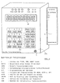
- the central control and monitor unit comprises a keypad for data entry and a visual display.
- This development of the invention enables the input of desired setpoints into the device, the visual display simultaneously enabling control over the correctness of the input made.
- the states measured by the sensors in the various rooms can also be made visible on the field of view. With the aid of this embodiment, the programming of the entire arrangement is also made possible.
- the control and monitor unit can expediently contain an acoustic alarm unit.
- it also contains an electronic clock, which can either be powered by a battery or can have a battery-powered buffer circuit. With the help of this clock, desired states, which are entered in advance via the keypad, can be established at the desired time. If the watch is either powered by a battery or has a buffer circuit, it continues to measure the time even when the central control unit is disconnected from the mains, e.g. because it should be carried to another room.
- the decentralized control units can also each comprise a microprocessor and an associated logic. This makes the entire arrangement applicable for the control and regulation of the entire building technology. In the case of heating alone, this arrangement according to the invention can save 25 to 50% of the energy required otherwise.
- Said actuating devices can be connected to rotary valves, slide valves, dampers and closing or other mechanical devices, e.g. with motors for operating roller shutters or blinds.
- the display of the heating costs per hour at the current heating output can be shown on the display.
- a sensor connected to a decentralized control unit can advantageously be provided for sensing the amount of fuel flowing through the fuel line per unit of time. Because of the flow rate and thus the flow rate per time, the current consumption in monetary value per unit of time can easily be calculated from the price of the fuel per amount and displayed on the central control and monitoring device.
- the invention also allows the respective over longer time intervals, e.g. save fuel quantities used during a week and display this value, if desired multiplied by the price per quantity, on the central control and monitoring device.
- this arrangement is programmable so that it learns independently how heating costs are saved. Starting from the fact that the temperature of the heating water initially has a certain difference to the outside temperature, it can initially be during a period of e.g. 3 days of fuel consumption measured and this value saved. The temperature gradient between the heating water temperature and the temperature outside the building can then be increased, and after 3 days the value of the amount of fuel used can be compared with the value of the amount of fuel that was used in the previous time interval.
- any suitable algorithms can be specified, which can then be carried out automatically by the arrangement according to the invention with the success that the energy consumption is automatically minimized.
- the mixer of the central heating system can also do so with the present invention be regulated so that the energy requirement is minimized.
- a scanner can be provided which continuously polls the states of the various sensors and / or the positions of the various actuating devices. This ensures constant monitoring.
- Non-volatile memories are advantageously provided. These ensure that the programmed and measured values are not lost, but remain saved even if the power supply to the house network fails.
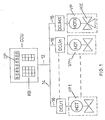
- FIG. 1 shows a central control and monitoring unit CCU, which contains a keypad KB and a visual display DP.
- This central control and monitoring unit CCU is connected via a line 12 to the power grid 14 of the building. This connection is done in the usual way with the help of a line and a plug that is plugged into a power socket.
- This figure also shows n decentralized control units DCU 1 to DCU n, each of which is connected to the power supply system of the building via a line 16.
- Each of these decentralized control units DCU is connected via a line 18 to a motor MOT, which in turn is connected to one of the valves PU 1,... PU n.
- the valves are radiator valves.
- a decentralized control unit DCU (MX) is also provided, which is connected to a motor MOT X, which in turn is connected to a mixing valve MX.
- FIG. 2 various components of the central control and monitoring unit CCU are shown in the shield delimited by dashed lines 20.
- a microcomputer MC is shown in the middle of this field, which essentially consists of a microprocessor MP and a read-only memory (ROM). This microcomputer MC communicates with an electrically changeable read-only memory or read-only memory EAROM.
- An electronic clock CL is also connected to the microprocessor MP.
- a scanner SC which communicates both with a visual display DP and with a keypad KB.
- This scanner can constantly display the DP and the KB via the keypad scan the entered values and send them to the Mikrocom forward computer.
- a modem M is provided in the left area of the field 20.
- the central control and monitoring unit CCU is connected to the mains 12 of the house via this modem M.
- the decentralized control units DCU control electric motors, which can adjust micro valves for heating radiators. All electronics are integrated in the DCU. This electronics includes the address decoder, the temperature sensor and the transmission circuit. For safety reasons, the motor and electronics work with a protective low voltage (below 42 V), which is obtained from the AC network via the network interfaces. The electric motor is able to move the valve not only to the "open” and “closed” end positions, but also to several intermediate positions, i.e. to bring different opening positions.
- the temperature sensor registers the room temperature and reports it to the DCU. This in turn opens or closes, completely or partially, with the microvalve to regulate the set temperature.
- the data transmission takes place via the lines of the power network (110/220 V; 50/60 Hz) by means of frequency-modulated signals.
- the data traffic is set up by the central control and monitoring unit CCU, and the addressed decentralized control unit DCU reports current parameters of your room (e.g. temperature, smoke present, etc.).
- the central control and monitor unit continuously polls all decentralized control units DCU, compares the programmed data with the actual data and controls the decentralized control unit DCU accordingly.
- the decentralized control units are only connected to a socket in the main power network.
- the decentralized control units can either control water valves for hot water central heating or air slides for heating with warm air or air conditioning systems. This does not change their function.
- the decentralized control units DCU can control several of them, one and the same device, but they can also control several external devices at the same time. This option is technically implemented by an "open collector" circuit. Alarm contacts or roller shutter actuation contacts of doors or windows can be connected to these two inputs / outputs. Control system can be expanded to house alarm and locking system without further significant costs. Such addressed window contacts can also be used to save energy. If there is ventilation in a room and the windows are accidentally left open for a long time, the room temperature drops very quickly when the outside temperature is lower. In most heating programs, after such a temperature drop in a room, with a certain time delay due to the measured low temperature, the heating valve is opened and the heating in this room is switched on.
- a further component can be connected to the thermal control arrangement according to the invention.
- This regulates the mixer which regulates the water flow temperature of the heating burner depending on the temperature gradients of the individual rooms in relation to the outside temperature.
- the construction of the mixer MX corresponds to that of the decentralized control unit DCU, however with the difference that a 4-way rotary valve is provided as the valve.
- the temperature sensor controls the water flow temperature.
- the described thermal control system is only one exemplary embodiment of the various possible uses of the arrangement according to the invention.
Abstract
Description
Die Erfindung betrifft eine Anordnung zur Einstellung und zur Voreinstellung von Ein- und Ausschaltvorgängen und von Zustandsbereichen in verschiedenen Räumen von Gebäuden.The invention relates to an arrangement for setting and presetting switch-on and switch-off processes and status areas in different rooms of buildings.
Solche Anordnungen sind in einfachster Form Lichtschalter, welche über eine Leitung die Einschaltung oder Ausschaltung einer Lampe in einem anderen Raum ermöglichen.Such arrangements are light switches in the simplest form, which enable a lamp to be switched on or off in another room via a line.
Bei diesen Anordnungen ist für jede zu schaltende Lampe eine separate zweiadrige oder, falls Erdleiter vorgeschrieben sind, sogar eine dreiadrige Leitung erforderlich. Will man nachträglich für eine Lampe einen Schalter in einem anderen Raum als dem, in welchem die Lampe sich befindet, haben, so gibt es üblicherweise drei Möglichkeiten: Man verwendet ein frei am Boden liegendes Kabel, was zum einen unschön ist und außerdem leicht zu einem Stolperdraht werden kann. Die zweite Möglichkeit besteht darin, eine Aufputzleitung zu verlegen, was allgemein als optisch unschön empfunden wird. Die dritte Möglichkeit ist die Verlegung einer Unterputzleitung, was - selbst bei der Erstellung von Neubauten - nur mit sehr großem Aufwand durchführbar ist.With these arrangements, a separate two-wire or, if earth conductors are prescribed, even a three-wire line is required for each lamp to be switched. If you later want to have a switch for a lamp in a room other than the one in which the lamp is located, there are usually three options: Man uses a cable lying freely on the ground, which is not nice on the one hand and can also easily become a trip wire. The second option is to lay a surface-mounted line, which is generally perceived as visually unattractive. The third option is to lay a flush-mounted pipe, which - even when building new buildings - can only be carried out with great effort.
Will man nicht nur eine, sondern mehrere Lampen in verschiedenen Räumen von einem Raum aus schalten können, so sind im allgemeinen entsprechend viele Leitungen erforderlich, wodurch sich die obigen Nachteile noch entsprechend vervielfältigen.If you want to be able to switch not only one but several lamps in different rooms from one room, a correspondingly large number of lines are generally required, as a result of which the above disadvantages are multiplied accordingly.
Aufgabe der Erfindung ist es, eine Anordnung zu schaffen, welche die Einstellung und die Voreinstellung von Ein- und Ausschaltvorgängen und von Zustandsbereichen in verschiedenen Räumen von Gebäuden' von einem Raum aus ermöglicht, welche die Nachteile der oben geschilderten Anordnungen vermeidet, mit geringem Kostenaufwand herstellbar ist und auch nach Fertigstellung des Gebäudes ohne großen Aufwand herstellbar ist.The object of the invention is to provide an arrangement which enables the setting and presetting of switch-on and switch-off processes and of state areas in different rooms of buildings from a room which avoids the disadvantages of the arrangements described above, can be produced at low cost is and can be produced without great effort even after completion of the building.
Die Aufgabe der Erfindung ist durch das Kennzeichen des Anspruchs 1 gelöst.The object of the invention is solved by the characterizing part of
Mit der Erfindung wird eine erstaunliche Vielzahl von Vorteilen erzielt:
- Zum einen ist der Vorteil zu nennen, daß Leitungen verwendet werden, welche ohnehin in dem Gebäude vorhanden sind, nämlich die Leitungen des Stromnetzes. Dieser Vorteil wird unabhängig davon erzielt, welche Art von Stromleitung im Gebäude vorhanden ist, sowohl bei 110 Volt- als auch bei 220 Volt-Netzen, sowohl bei Gleichstrom- als auch bei Wechselstromnetzen, sowohl bei 50 Hz- als auch bei 60 Hz-Wechselstromnetzen.
- On the one hand, there is the advantage that lines are used which are already present in the building, namely the lines of the power grid. This advantage is achieved regardless of what type of power line is available in the building, both 110 volt and 220 volt networks, both DC and AC, both 50 Hz and 60 Hz AC .
Für die erfindungsgemäße Anordnung müssen somit keine separaten Leitungen von dem Raum, von dem aus die Fernsteuerung erfolgen soll, zu den dezentralen Steuereinheiten verlegt werden. Dadurch wird zum einen viel Material gespart. Zum anderen ist diese erfindungsgemäße Anordnung auch deshalb besonders kostengünstig, weil sie auch nachträglich in beliebige Gebäude eingebaut oder einfach eingesetzt werden kann.For the arrangement according to the invention, therefore, no separate lines have to be laid from the room from which remote control is to take place to the decentralized control units. On the one hand, this saves a lot of material. On the other hand, this arrangement according to the invention is also particularly cost-effective because it can also be retrofitted into any building or simply used.
Ein weiterer, ganz erheblicher Vorteil der vorliegenden Erfindung liegt darin, daß der Benutzer sich nicht festlegen muß, wo er seine zentrale Steuer-und Monitoreinheit haben möchte. Selbst wenn die gesamte Anordnung oder Anlage bereits installiert ist, kann er sie in denkbar einfacher Weise umbauen. Nicht nur wenn er die gesamte Wohnung umräumt, sondern auch zu beliebigen Zeiten hat er diese Möglichkeit. Zu diesem Zweck muß er nur den Stecker der zentralen Steuer- und Monitoreinheit aus der Steckdose ziehen, diese Steuer- und Monitoreinheit in ein anderes Zimmer mitnehmen, zum Beispiel abends in das Schlafzimmer, und dort den Stecker dieser Einheit wieder in die nächste Steckdose stecken.Another very significant advantage of the present invention is that the user does not have to determine where he wants his central control and monitoring unit to be. Even if the entire arrangement or system is already installed, he can convert it in a very simple way. Not only when he moves the entire apartment around, but also at any time he has this opportunity. For this purpose, he only has to pull the plug of the central control and monitor unit out of the socket, take this control and monitor unit to another room, for example in the evening in the bedroom, and then put the plug of this unit back into the next socket.
Aber auch der Umbau der Anordnung in den einzelnen Räumen ist denkbar einfach, weil eine zusätzliche dezentrale Steuereinheit oder eine zu verlegende dezentrale Steuereinheit einfach durch Anschluß an das vorhandene Stromnetz gleichzeitig mit der zentralen Steuer- und Monitoreinheit verbunden wird, ganz gleich in welchem Raum der Wohnung und an welcher Stelle sich dort die zentrale Steuer-und Monitoreinheit befindet.But also the conversion of the arrangement in the individual rooms is very easy, because an additional decentralized control unit or a decentralized control unit to be relocated is simply connected to the central control and monitor unit by connecting to the existing power supply, regardless of the room in the apartment and at which point the central control and monitor unit is located.
Die Erfindung weist weiterhin den Vorteil auf, daß sie sowohl innerhalb eines geschlossenen Raumes als auch in Ein- und Mehrfamilienhäusern als auch in beliebig großen Büro- oder Fabrikgebäuden verwendbar ist. Je mehr dezentrale Steuereinheiten zur Auslösung von Schalt- oder Steuerschritten von der Zentrale aus ferngesteuert werden sollen und je weiter fort von der Zentrale diese dezentralen Steuereinheiten angeordnet sind, umso stärker kommt der durch die Erfindung erzielte Vorteil der Materialersparnis und der Ersparnis an Arbeitsaufwand zum Tragen.The invention also has the advantage that it can be used both in an enclosed space and in single and multi-family houses, as well as in office or factory buildings of any size. The more decentralized control units for triggering switching or control steps are to be remotely controlled from the central and the farther away these decentralized control units are arranged from the central, the more the advantage of the material savings and the saving on workload achieved by the invention comes into play.
Die dezentralen Steuereinheiten können mit Schaltern elektrischer Einrichtungen verbunden sein. Solche Einrichtungen können im einfachsten Fall Lampen sein, es können aber auch z.B. Schalter einer Kaffeemaschine, eines Radios oder eines Backofens sein.The decentralized control units can be connected to switches of electrical devices. In the simplest case, such devices can be lamps, but it can also be, for example, a switch A coffee machine, a radio or an oven.
Nach einer Weiterbildung der Erfindung sind Motoren vorgesehen, welche von den dezentralen Steuereinheiten steuerbar sind. Diese Motoren können mit Stellgliedern verbunden sein. Diese Weiterbildung der Erfindung ermöglicht ihre Anwendung auf die Fernsteuerung nahezu beliebiger einstellbarer Gegenstände des Hauses, z.B. von Rolläden, Jalousien oder dergleichen. Dabei können die zu steuernden Einrichtungen entweder von einer Endstellung in die andere Endstellung gesteuert werden, oder aber, mit Hilfe der Stellglieder, auch in gewünschte Zwischenstellungen.According to a development of the invention, motors are provided which can be controlled by the decentralized control units. These motors can be connected to actuators. This development of the invention enables its application to the remote control of almost any adjustable objects in the house, e.g. of shutters, blinds or the like. The devices to be controlled can either be controlled from one end position to the other end position, or, with the help of the actuators, also into the desired intermediate positions.
Zweckmäßigerweise weisen sowohl die zentrale Steuer-und Motoreinheit, also auch die dezentralen Steuereinheiten Netz-Schnittstellen auf. Diese Schnittstelllen dienen zur Trennung der Niederspannungselektronik von der Stromspannung und gleichzeitig zur Übertragung der Signale von der Elektronik auf das Netz und umgekehrt zur Übertragung der Signale von dem Netz in die zentrale Steuereinheit bzw. in die dezentralen Steuereinheiten.The central control and motor unit, and therefore also the decentralized control units, expediently have network interfaces. These interfaces serve to separate the low-voltage electronics from the voltage and at the same time to transmit the signals from the electronics to the network and vice versa to transmit the signals from the network to the central control unit or to the decentralized control units.
Die dezentralen Steuereinheiten sind nach einer anderen Seite der Erfindung direkt mit den Stellgliedern verbunden. Diese direkte Verbindung kann über eine ganz normale Leitung erfolgen.According to another side of the invention, the decentralized control units are connected directly to the actuators. This direct connection can be made via a normal line.
Ein besonderes Problem in der Haustechnik bildet stets die Heizung desselben. Bei Zentralheizungsaniagen in Ein- oder Mehrfamilienhäusern wird die Heizung über einen zentralen Thermostaten derart gesteuert, daß das Heizungswasser oder die Heizungsluft im Brenner immer derartig erhitzt wird, daß die einzelnen Räume des Hauses gewisse Minimal-oder Maximaltemperaturen aufweisen können. In der Regel wird diese Zentralsteuerung auf Maximaltemperatur eingestellt sein, um bei Bedarf kurzfristig die benötigte Heizenergie in jedem gewünschten Raum zur Verfügung zu stellen. In den einzelnen Räumen sind an den Heizkörpern mechanische oder thermostatische Ventile angebracht, die vom Benutzer einzeln eingestellt werden müssen, wenn er den Raum heizen will. Hierbei ist festzustellen, daß bei rein mechanischen Ventilen der Benutzer in der Regel nur "auf" oder "zu" einstellt, während bei Thermoventilen ein angenäherter Temperaturbereich eingestellt werden könnte. Letzterer kann die Raumtemperatur im Prinzip konstant halten, wenn auch nur verzögert, jedoch auch diese Möglichkeit wird nur von den wenigsten Benutzern tatsächlich ausgenutzt. Erfahrungsgemäß nutzen diese Systeme deshalb nur sehr wenig, weil die Überprüfung und das Herausfinden ihrer zweckmäßigsten Stellung etwas mühsam ist und keine geeigneten Kontrollmöglichkeiten vorgegeben sind. In der Regel sind die Räume in Gebäuden zu kalt oder zu warm, wobei sehr häufig im letzteren Fall die Fenster geöffnet werden, um die Warmtemperatur wieder abzukühlen. Aus diesen Gründen wird sehr viel Primärenergie unnötig verschwendet.The heating of the building technology is always a particular problem. With central heating system conditions in single or multi-family houses, the heating is controlled by a central thermostat in such a way that the heating water or the heating air in the burner is always heated in such a way that the individual rooms of the house can have certain minimum or maximum temperatures. As a rule, this central control will be set to maximum temperature in order to provide the required heating energy in any desired room at short notice if required. Mechanical or thermostatic valves are attached to the radiators in the individual rooms, which must be set individually by the user if he wants to heat the room. It should be noted that in the case of purely mechanical valves, the user generally only sets "open" or "closed", whereas an approximate temperature range could be set for thermostatic valves. The latter can keep the room temperature constant in principle, even if only with a delay, but this option is actually only used by very few users. Experience has shown that these systems use very little because checking and finding their most appropriate position is a bit tedious and there are no suitable control options. As a rule, the rooms in buildings are too cold or too warm, with the windows being opened very frequently in the latter case in order to cool down the warm temperature again. For these reasons, a lot of primary energy is wasted unnecessarily.
Hinzu kommt das Problem, daß bei günstiger Ausnutzung der Heizenergie der Benutzer die Einstellung an jedem Heizkörper in jedem Raum täglich mehrmals vornehmen solte, um den Energieverbrauch den sich im Tagesverlauf ändernden tatsächlichen Heizbedürfnissen anzupassen. Das ist natürlich mit Aufwand verbunden und wird daher nicht durchgeführt. Die Folge ist, daß Heizkörper in Räumen, die nur zeitweise benutzt werden, ständig angestellt bleiben, was wiederum zu erhöhtem Energieverbrauch und damit zu einer Energieverschwendung führt. Es ist einfach eine Tatsache, daß so gut wie kein Raum individuell und entsprechend dem tatsächlichen Bedarf beheizt wird.In addition, there is the problem that if the heating energy is used favorably, the user should make the setting on each radiator in each room several times a day in order to adapt the energy consumption to the actual heating requirements which change over the course of the day. Of course, this is associated with effort and is therefore not carried out. The result is that radiators in rooms that are only used temporarily remain on, which in turn leads to increased energy consumption and thus to energy waste. It is simply a fact that almost no room is heated individually and according to actual needs.
Dieses Problem wird durch eine bevorzugte Weiterbildung gelöst, nach welcher die dezentralen Steuereinheiten kommunizierend mit Fühlern verbunden sind. Diese Fühler können Temperaturfühler sein, welche im Abstand von den dezentralen Steuereinheiten angeordnet sind, oder welche zusammen mit einer dezentralen Steuereinheit in einer einzigen Baueinheit angeordnet sind. Es können auch mehrere Temperaturfühler in einem Raum angeordnet sein, welche alle mit einer dezentralen Steuereinheit in diesem Raum kommunizieren. Mit dieser Weiterbildung dieser Erfindung ist es möglich, von der zentralen Steuer-und Monitoreinheit aus in jedem beliebigen Raum die gewünschte Temperatur einzustellen, wodurch erhebliche Heizkosten eingespart werden können.This problem is solved by a preferred further development, according to which the decentralized control units are communicatively connected to sensors. These sensors can be temperature sensors which are arranged at a distance from the decentralized control units or which are arranged together with a decentralized control unit in a single structural unit. A plurality of temperature sensors can also be arranged in a room, all of which communicate with a decentralized control unit in this room. With this development of this invention, it is possible to set the desired temperature in any room from the central control and monitor unit, thereby saving considerable heating costs.
Aber auch diese Weiterbildung der Erfindung ist keineswegs auf die Anwendung der Heizregulierung beschränkt. Statt Temperaturfühlern können auch andere Fühler vorgesehen sein, z.B. Rauchfühler, welche ein Alarmsignal bei der zentralen Steuer-und Monitoreinheit auslösen, wenn die Rauchmenge in einem Raum einen bestimmten Schwellwert überschreitet. Diese Weiterbildung der Erfindung kann somit z.B. gleichzeitig als Feuermelder verwendet werden. Diese Anlage kann gleichzeitig auch als Feuermelder mit Alarmzeichen in der Zentrale verwendet werden. Somit kann bei Ausbrechen eines Brandes mit Hilfe der zentralen Steuereinrichtung über die dezentralen Steuereinrichtungen die Sprinkleranlage genau in den gewünschten Räumen und an den gewünschten Stellen in Betrieb gesetzt werden.But this development of the invention is also in no way limited to the application of heating regulation. Instead of temperature sensors, other sensors can also be provided, for example smoke sensors, which trigger an alarm signal at the central control and monitoring unit if the amount of smoke in a room exceeds a certain threshold value. This development of the invention can thus be used simultaneously as a fire alarm, for example. This system can also be used as a fire alarm with alarm signals in the control center. Thus, if a fire breaks out with the help of the central control device via the decentralized control devices, the sprinkler system can be put into operation exactly in the desired rooms and at the desired locations.
Es ist möglich, sowohl die dezentralen Steuereinheiten als auch die Fühler und die Stelleinrichtung jeweils innerhalb einer gemeinsamen Baueinheit anzuordnen. Diese Weiterbildung der Erfindung erlaubt es, in den verschiedenen Räumen mit jeweils nur einer Baueinheit auszukommen.It is possible to arrange the decentralized control units as well as the sensors and the actuating device in each case within a common structural unit. This development of the invention makes it possible to manage with only one structural unit in the different rooms.
Die zentrale Steuer- und Monitoreinheit umfaßt nach einer Weiterbildung der Erfindung einen Mikroprozessor und eine zugeordnete Logikschaltung. Diese Weiterbildung der Erfindung ermöglicht eine Anordnung, welche aufgrund der von den verschiedenen Fühlern festgestellten Zuständen selbständig ermittelt, welche Schaltvorgänge oder Schaltschritte vorgenommen werden müssen und welche Stellglieder in welche Position gefahren werden sollten, und welche dann diese Vorgänge auslöst.According to a further development of the invention, the central control and monitor unit comprises a microprocessor and an associated logic circuit. This development of the invention enables an arrangement which, on the basis of the states determined by the various sensors, independently determines which switching operations or switching steps must be carried out and which actuators should be moved into which position, and which then triggers these processes.
Die zentrale Steuer- und Monitoreinheit umfaßt nach einer anderen Weiterbildung der Erfindung ein Tastenfeld zur Dateneingabe und eine Sichtanzeige. Diese Weiterbildung der Erfindung ermöglicht die Eingabe gewünschter Sollwerte in die Einrichtung, wobei die Sichtanzeige gleichzeitig die Kontrolle über die Richtigkeit der vorgenommenen Eingabe ermöglicht. Auf dem Sichtfeld können aber auch die von den Fühlern in den verschiedenen Räumen gemessenen Zustände sichtbar gemacht werden. Mit Hilfe dieser Ausführungsform ist auch die Programmierung der gesamten Anordnung ermöglicht.According to another development of the invention, the central control and monitor unit comprises a keypad for data entry and a visual display. This development of the invention enables the input of desired setpoints into the device, the visual display simultaneously enabling control over the correctness of the input made. The states measured by the sensors in the various rooms can also be made visible on the field of view. With the aid of this embodiment, the programming of the entire arrangement is also made possible.
Zweckmäßigerweise kann die Steuer- und Monitoreinheit eine akustische Alarmeinheit enthalten. Nach einer anderen Weiterbildung der Erfindung enthält sie auch eine elektronische Uhr, welche entweder von einer Batterie gespeist sein oder eine batteriegespeiste Pufferschaltung aufweisen kann. Mit Hilfe dieser Uhr können zu beliebigen Zeiten gewünschte Zustände, die im voraus über das Tastenfeld eingegeben werden, zur gewünschten Zeit hergestellt werden. Wenn die Uhr entweder von einer Batterie gespeist wird oder aber eine Pufferschaltung aufweist, mißt sie auch dann weiterhin die Zeit, wenn die zentrale Steuereinheit vom Netz getrennt ist, z.B. weil sie in einen anderen Raum getragen werden soll.The control and monitor unit can expediently contain an acoustic alarm unit. According to another development of the invention, it also contains an electronic clock, which can either be powered by a battery or can have a battery-powered buffer circuit. With the help of this clock, desired states, which are entered in advance via the keypad, can be established at the desired time. If the watch is either powered by a battery or has a buffer circuit, it continues to measure the time even when the central control unit is disconnected from the mains, e.g. because it should be carried to another room.
Nach einer anderen Weiterbildung können auch die dezentralen Steuereinheiten jeweils einen Mikroprozessor und eine zugeordnete Logik umfassen. Damit wird die gesamte Anordnung für die Steuerung und Regelung der gesamten Haustechnik anwendbar. Allein bei der Heizung können mit dieser erfindungsgemäßen Anordnung 25 bis 50 % des sonst erforderlichen Energiebedarfs eingespart werden.According to another further development, the decentralized control units can also each comprise a microprocessor and an associated logic. This makes the entire arrangement applicable for the control and regulation of the entire building technology. In the case of heating alone, this arrangement according to the invention can save 25 to 50% of the energy required otherwise.
Erhebliche Energieersparung wird auch bei Anwendung der erfindungsgemäßen Anordnung zur Steuerung von Klimaanlagen in den verschiedenen Räumen eines Gebäudes eingespart werden.Significant energy savings will also be saved when using the arrangement according to the invention for controlling air conditioning systems in the different rooms of a building.
Die genannten Stelleinrichtungen können mit Drehschiebern, Schieberventilen, Dämpfern und Schließ-oder anderen mechanischen Einrichtungen verbunden sein, z.B. mit Motoren zur Betätigung von Rolläden oder Jalousien.Said actuating devices can be connected to rotary valves, slide valves, dampers and closing or other mechanical devices, e.g. with motors for operating roller shutters or blinds.
Nach einer anderen Ausführungsform der Erfindung ist die Anzeige der Heizkosten pro Stunde bei der gegenwärtigen Heizleistung auf der Anzeige darstellbar. Zu diesem Zweck kann vorteilhafterweise ein mit einer dezentralen Steuereinheit verbundener Fühler zum Fühlen der pro Zeiteinheit durch die Brennstoffleitung strömende Brennstoffmenge vorgesehen sein. Aufgrund der Durchflußgeschwindigkeit und damit der Durchflußmenge pro Zeit kann über den Preis des Brennstoffs pro Menge leicht der gegenwärtige Verbrauch in Geldwert pro Zeiteinheit ausgerechnet und an der zentralen Steuer- und Monitoreinrichtung angezeigt werden.According to another embodiment of the invention, the display of the heating costs per hour at the current heating output can be shown on the display. For this purpose, a sensor connected to a decentralized control unit can advantageously be provided for sensing the amount of fuel flowing through the fuel line per unit of time. Because of the flow rate and thus the flow rate per time, the current consumption in monetary value per unit of time can easily be calculated from the price of the fuel per amount and displayed on the central control and monitoring device.
Selbstverständlich erlaubt die Erfindung es auch, die jeweils über längere Zeitintervalle, z.B. während einer Woche, verbrauchten Brennstoffmengen zu speichern und diesen Wert, auf Wunsch multipliziert mit dem Preis pro Menge, auf der zentralen Steuer-und Monitoreinrichtung anzuzeigen.Of course, the invention also allows the respective over longer time intervals, e.g. save fuel quantities used during a week and display this value, if desired multiplied by the price per quantity, on the central control and monitoring device.
Ein weiterer ganz wesentlicher Vorteil der Erfindung liegt darin, daß diese Anordnung so programmierbar ist, daß sie selbständig lernt, wie Heizkosten eingespart werden. Ausgehend davon, daß zunächst die Temperatur des Heizwassers eine bestimmte Differenz zur Außentemperatur aufweist, kann zunächst während einer Zeit von z.B. 3 Tagen der Brennstoffverbrauch gemessen und dieser Wert gespeichert werden. Anschliessend kann der Temperaturgradient zwischen Heizwassertemperatur und der Temperatur außerhalb des Gebäudes erhöht werden, und nach 3 Tagen kann der Wert der verbrauchten Brennstoffmenge mit dem Wert der Brennstoffmenge verglichen werden, welche in dem zuvor liegenden Zeitintervall verbraucht wurde. Selbstverständlich können beliebige geeignete Algorithmen vorgegeben werden, welche dann selbsttätig von der erfindungsgemäßen Anordnung durchgeführt werden können mit dem Erfolg, daß der Energieverbrauch automatisch minimiert wird.Another very important advantage of the invention is that this arrangement is programmable so that it learns independently how heating costs are saved. Starting from the fact that the temperature of the heating water initially has a certain difference to the outside temperature, it can initially be during a period of e.g. 3 days of fuel consumption measured and this value saved. The temperature gradient between the heating water temperature and the temperature outside the building can then be increased, and after 3 days the value of the amount of fuel used can be compared with the value of the amount of fuel that was used in the previous time interval. Of course, any suitable algorithms can be specified, which can then be carried out automatically by the arrangement according to the invention with the success that the energy consumption is automatically minimized.
Selbstverständlich kann mit der vorliegenden Erfindung auch der Mischer des Zentralheizungssystems so geregelt werden, daß der Energiebedarf minimiert wird.Of course, the mixer of the central heating system can also do so with the present invention be regulated so that the energy requirement is minimized.
Es kann ein Scanner vorgesehen sein, welcher ständig zyklisch die Zustände der verschiedenen Fühler und/oder der Stellungen der verschiedenen Stelleinrichtungen abfragt. Auf diese Weise wird eine ständige Überwachung gewährleistet.A scanner can be provided which continuously polls the states of the various sensors and / or the positions of the various actuating devices. This ensures constant monitoring.
Vorteilhafterweise sind nicht-flüchtige Speicher vorgesehen. Diese gewährleisten, daß auch bei Ausfall des Stroms des Hausnetzes die einprogrammierten und die bereits gemessenen Werte nicht verloren gehen, sondern gespeichert bleiben.Non-volatile memories are advantageously provided. These ensure that the programmed and measured values are not lost, but remain saved even if the power supply to the house network fails.
Vorteilhafterweise sind Einrichtungen zur Speisung der Elektronik aus dem Stromnetz vorgesehen.Devices for supplying the electronics from the power grid are advantageously provided.
Die Erfindung ist im folgenden anhand eines Ausführungsbeispiels und in Verbindung mit der Zeichnung näher beschrieben. In letzterer zeigen:
- Fig. 1 eine schematische Anordnung gemäß der Erfindung (mit einer zentralen Steuer- und Monitoreinheit) mit dezentralen Steuereinheiten und mit Stellgliedern,
- Fig. 2 eine weitere schematische Schaltungsanordnung gemäß der Erfindung (in welcher verschiedene Komponenten der zentralen Steuer- und Monitoreinheit dargestellt sind),
- Fig. 3 eine perspektivische Ansicht der zentralen Steuer- und Monitoreinheit mit Legende.
- 1 shows a schematic arrangement according to the invention (with a central control and monitor unit) with decentralized control units and with actuators,
- Fig. 2 shows a further schematic circuit arrangement according to the invention (in which various components of the central control and monitor are shown),
- Fig. 3 is a perspective view of the central control and monitor unit with legend.
In Figur 1 ist eine zentrale Steuer- und Monitoreinheit CCU dargestellt, welche ein Tastenfeld KB und eine Sichtanzeige DP enthält. Diese zentrale Steuer- und Monitoreinheit CCU ist über eine Leitung 12 mit dem Stromnetz 14 des Gebäudes verbunden. Diese Verbindung geschieht in üblicher Weise mit Hilfe einer Leitung und eines Steckers, der in eine Netzdose eingesteckt ist.FIG. 1 shows a central control and monitoring unit CCU, which contains a keypad KB and a visual display DP. This central control and monitoring unit CCU is connected via a
In dieser Figur sind ferner n dezentrale Steuereinheiten DCU 1 bis DCU n dargestellt, welche jeweils über eine Leitung 16 mit dem Stromnetz des Gebäudes verbunden sind. Jede dieser dezentralen Steuereinheiten DCU ist über eine Leitung 18 mit einem Motor MOT verbunden, welcher seinerseits jeweils mit einem der Ventile PU 1, ... PU n verbunden ist. Bei diesem Ausführungsbeispiel sind die Ventile Heizkörperventile.This figure also shows n decentralized
Wie in dem rechten Teil der Figur sichtbar ist, ist ferner eine dezentrale Steuereinheit DCU (MX) vorgesehen, welche mit einem Motor MOT X verbunden ist, der seinerseits mit einem Mischventil MX verbunden ist.As can be seen in the right part of the figure, a decentralized control unit DCU (MX) is also provided, which is connected to a motor MOT X, which in turn is connected to a mixing valve MX.
Wie man an dieser einfachen Prinzipskizze bereits erkennt, sind zur Installation der gesamten Anordnung lediglich Leitungsverbindungen von den Steuereinheiten zur jeweils nächsten Steckdose erforderlich. Die dezentralen Steuereinheiten DCU schalten Motoren, welche die verschiedenen Ventile öffnen und schließen. Für die Verbindung von den dezentralen Steuereinheiten zu dem jeweils zugeordneten Motor sind im Ausführungsbeispiel ebenfalls feste Leitungen vorgesehen. Es sind aber auch drahtlose Verbindungen möglich.How to do this simple sketch recognizes, all that is required to install the entire arrangement is line connections from the control units to the next socket. The decentralized control units DCU switch motors that open and close the various valves. Fixed lines are also provided in the exemplary embodiment for the connection from the decentralized control units to the respectively assigned motor. However, wireless connections are also possible.
In Figur 2 sind in dem durch gestrichelte Linien 20 eingegrenzten Schild verschiedene Komponenten der zentralen Steuer- und Monitoreinheit CCU dargestellt.In FIG. 2, various components of the central control and monitoring unit CCU are shown in the shield delimited by dashed lines 20.
Im mittleren Bereich dieses Feldes ist ein Mikrocomputer MC dargestellt, welcher im wesentlichen aus einem Mikroprozessor MP und einem Nur-Lese-Speicher (ROM) besteht. Dieser Mikrocomputer MC kommuniziert mit einem elektrisch änderbaren Nur-Lese-Speicher oder Festwertspeicher EAROM.A microcomputer MC is shown in the middle of this field, which essentially consists of a microprocessor MP and a read-only memory (ROM). This microcomputer MC communicates with an electrically changeable read-only memory or read-only memory EAROM.
Mit dem Mikroprozessor MP ist ferner eine elektronische Uhr CL verbunden.An electronic clock CL is also connected to the microprocessor MP.
In dem rechten Bereich dieses Feldes 20 sieht man einen Abtaster SC, welcher sowohl mit einer Sichtanzeige DP als auch mit einem Tastenfeld KB kommuniziert. Dieser Scanner kann ständig die Sichtanzeige DP und die über das Tastenfeld KB
eingegebenen Werte abtasten und an den Mikrocomputer weiterleiten.In the right area of this field 20 one can see a scanner SC, which communicates both with a visual display DP and with a keypad KB. This scanner can constantly display the DP and the KB via the keypad
scan the entered values and send them to the Mikrocom forward computer.
Ferner ist in dem linken Bereich des Feldes 20 ein Modem M vorgesehen. Über dieses Modem M ist die zentrale Steuer- und Monitoreinheit CCU mit dem Stromnetz 12 des Hauses verbunden.Furthermore, a modem M is provided in the left area of the field 20. The central control and monitoring unit CCU is connected to the
In der unteren Hälfte dieser Figur 2 sieht man wiederum verschiedene dezentrale Steuereinheiten DCU, welche jeweils ein Modem M enthalten. Verbunden mit diesen DCU's sind Stellmotoren, welche in verschiedenen Stellungen anhalten können. Im Ausführungsbeispiel werden diese Motoren zum Einstellen von Heizkörperventilen VP verbunden.In the lower half of this FIG. 2 you can see various decentralized control units DCU, each of which contains a modem M. Connected to these DCUs are servomotors, which can stop in different positions. In the exemplary embodiment, these motors are connected to set radiator valves VP.
Die dezentralen Steuereinheiten DCU steuern Elektromotoren, welche Mikroventile für Heizradiatoren verstellen können. In der DCU ist jeweils die gesamte Elektronik integriert. Diese Elektronik beinhaltet den Adreßdekoder, den Temperaturfühler und die Übertragungsschaltung. Aus Sicherheitsgründen arbeiten der Motor und die Elektronik mit einer Schutzkleinspannung (unter 42 V), die über die Netz-Schnittstellen aus dem Wechselstromnetz gewonnen wird. Der Elektromotor ist in der Lage, das Ventil nicht nur in die Endstellungen "auf" und "zu", sondern auch in mehrere Zwischenstellungen, d.h. verschiedene Öffnungsstellungen, zu bringen.The decentralized control units DCU control electric motors, which can adjust micro valves for heating radiators. All electronics are integrated in the DCU. This electronics includes the address decoder, the temperature sensor and the transmission circuit. For safety reasons, the motor and electronics work with a protective low voltage (below 42 V), which is obtained from the AC network via the network interfaces. The electric motor is able to move the valve not only to the "open" and "closed" end positions, but also to several intermediate positions, i.e. to bring different opening positions.
Der Temperaturfühler registriert die Raumtemperatur und meldet sie an die DCU. Diese wiederum öffnet oder schließt, vollständig oder teilweise, mit dem Elektromotor das Mikroventil, um die eingestellte Temperatur auszuregeln.The temperature sensor registers the room temperature and reports it to the DCU. This in turn opens or closes, completely or partially, with the microvalve to regulate the set temperature.
Die Datenübertragung erfolgt über die Leitungen des Stromnetzes (110/220 V; 50/60 Hz) mittels frequenzmodulierter Signale. Der Datenverkehr wird von der zentralen Steuer- und Monitoreinheit CCU aufgebaut, und die angesprochene dezentrale Steuereinheit DCU meldet aktuelle Parameter ihres Raumes (z.B. Temperatur, Rauch vorhanden usw.). Die zentrale Steuer- und Monitoreinheit fragt permanent alle dezentralen Steuereinheiten DCU zyklisch ab, vergleicht die programmierten Daten mit den Ist-Daten und steuert die dezentrale Steuereinheit DCU entsprechend neu an. Die dezentralen Steuereinheiten werden ebenfalls wie die zentrale Steuer- und Monitoreinheit nur an eine Steckdose des Hauptstromnetzes angeschlossen. Die dezentralen Steuereinheiten können in Verbindung mit dem Ventilstellglied (VP) entweder Wasserventile für Warmwasserzentralheizungen oder Luftschieber für Heizungen mit Warmluft oder Klimaanlagen ansteuern. Ihre Funktion ändert sich hierdurch nicht.The data transmission takes place via the lines of the power network (110/220 V; 50/60 Hz) by means of frequency-modulated signals. The data traffic is set up by the central control and monitoring unit CCU, and the addressed decentralized control unit DCU reports current parameters of your room (e.g. temperature, smoke present, etc.). The central control and monitor unit continuously polls all decentralized control units DCU, compares the programmed data with the actual data and controls the decentralized control unit DCU accordingly. Like the central control and monitor unit, the decentralized control units are only connected to a socket in the main power network. In combination with the valve actuator (VP), the decentralized control units can either control water valves for hot water central heating or air slides for heating with warm air or air conditioning systems. This does not change their function.
Die dezentralen Steuereinheiten DCU können, jeweils mehrere von ihnen, ein und dasselbe Gerät steuern, sie können aber auch mehrere äußere Geräte gleichzeitig steuern. Diese Option wird technisch durch eine "open collector"-Schaltung realisiert. An diese beiden Ein-/Ausgänge können somit Alarmkontakte oder Rolladenbetätigungskontakte von Türen oder Fenstern angeschlossen werden, wodurch das Thermo-Control-System ohne weitere erhebliche Kosten zum Hausalarm und Schließsystem ausgebaut werden kann. Solche angesprochenen Fensterkontakte können aber auch zur Energieeinsparung verwendet werden. Wenn in einem Raum gelüftet wird und die Fenster versehentlich längere Zeit offengelassen werden, fällt, wenn die Außentemperatur niedriger ist, die Raumtemperatur sehr schnell ab. Bei den meisten Heizungsprogrammen wird, nach einem solchen Temperaturabfall in einem Raum, mit einer gewissen Zeitverzögerung, wegen der gemessenen niedrigen Temperatur, das Heizventil geöffnet und damit die Heizung in diesem Raum eingeschaltet werden. Wenn ein Fenster versehentlich längere Zeit offengelassen wird, hätte dies den Erfolg, daß, wegen der falschen Bedienung, gerade mit einem Energiesparsystem unnötig viel Heizöl verbrannt wird. Dies kann dadurch verhindert werden, daß beim Öffnen des Fensters durch Meldung von den Fensterkontakten an die dezentrale Steuereinheit DCU ein Signal abgegeben wird, aufgrunddessen das Heizkörperventil in diesem Raum geschlossen wird, unabhängig von der Raumtemperatur.The decentralized control units DCU can control several of them, one and the same device, but they can also control several external devices at the same time. This option is technically implemented by an "open collector" circuit. Alarm contacts or roller shutter actuation contacts of doors or windows can be connected to these two inputs / outputs. Control system can be expanded to house alarm and locking system without further significant costs. Such addressed window contacts can also be used to save energy. If there is ventilation in a room and the windows are accidentally left open for a long time, the room temperature drops very quickly when the outside temperature is lower. In most heating programs, after such a temperature drop in a room, with a certain time delay due to the measured low temperature, the heating valve is opened and the heating in this room is switched on. If a window is accidentally left open for a long time, the result would be that, due to incorrect operation, an energy-saving system, in particular, burns unnecessarily a lot of heating oil. This can be prevented by a signal from the window contacts being sent to the decentralized control unit DCU when the window is opened, as a result of which the radiator valve in this room is closed, regardless of the room temperature.
Als Option kann bei der erfindungsgemäßen Thermo-Control-Anordnung eine weitere Komponente angeschlossen werden. Diese regelt den Mischer, der die Wasservorlauftemperatur des Heizungsbrenners in Abhängigkeit von den Temperaturgradienten der einzelnen Räume bezogen auf die Außentemperatur regelt. Der Aufbau des Mischers MX entspricht dem der dezentralen Steuereinheit DCU, jedoch mit dem Unterschied, daß als Ventil ein 4-Wege-Drehventil vorgesehen ist. Der Temperaturfühler kontrolliert die Wasservorlauftemperatur. Bei Einsatz dieser Komponente wird eine weitere Energieeinsparung erzielt, da hiermit die benötigte Primärenergie zur Erhitzung des Heizungswassers wesentlich besser dosiert werden kann, weil der Temperaturgradient entsprechend dem Programm berücksichtigt wird.As an option, a further component can be connected to the thermal control arrangement according to the invention. This regulates the mixer, which regulates the water flow temperature of the heating burner depending on the temperature gradients of the individual rooms in relation to the outside temperature. The construction of the mixer MX corresponds to that of the decentralized control unit DCU, however with the difference that a 4-way rotary valve is provided as the valve. The temperature sensor controls the water flow temperature. When using this component, further energy savings are achieved since the primary energy required to heat the heating water can be metered much better because the temperature gradient is taken into account in accordance with the program.
Die wichtigsten Merkmale dieses Ausführungsbeispiels, welches ein Thermo-Control-System betrifft, sind zusammengefaßt in die folgenden:
- Die wichtigsten Merkmale dieses Ausführungsbeispiels, die zentrale Steuer- und Monitoreinheit CCU, wird im Hauptwohnraum, z.B. an der Wand, installiert;
- die Stelleinrichtungen VP werden in jedem Raum an jedem Heizkörper installiert;
- am Heizungsbrenner wird, falls es erwünscht ist, ein Mischer installiert;
- der Benutzer kann mit der zentralen Steuer-und Monitoreinrichtung CCU die Temperatur jedes Raumes vorprogrammieren und kontrollieren, ohne daß er in die verschiedenen Räume oder
- gar zu den einzelnen Heizkörpern gehen müßte; die Temperatur kann automatisch oder zeitabhängig oder durch Direkteingabe angehoben oder abgesenkt werden;
- es können bis zu 15 Räume kontrolliert werden, und, bei Einsatz eines zusätzlichen Moduls, bis zu 256 Räume;
- durch automatische Kontrolle und Programme werden 25 bis 50 % der Primärenergie eingespart; die Bedienung des Systems ist sehr leicht und bequem;
- das System kann kostengünstig in alten und in neuen Häusern installiert werden;
- es ist keine spezielle Verdrahtung für die Installation erforderlich, vielmehr wird das in jedem Haus vorhandene Stromnetz zur Steuerung benutzt;
- aufgrund der Möglichkeit, durch einen Erweiterungsbaustein das System auf 256 Räume zu erweitern, ist es auch für größere Wohnhäuser,
- Bürogebäude oder Hotels günstig anwendbar; und mit einem Erweiterungsbaustein in den dezentralen Steuereinheiten DCU kann das System zu einem Haus-Alarm- und Schließsystem erweitert werden.
- The most important features of this exemplary embodiment, the central control and monitoring unit CCU, are installed in the main living room, for example on the wall;
- VP actuators are installed on every radiator in every room;
- If desired, a mixer is installed on the heating burner;
- With the central control and monitoring device CCU, the user can pre-program and control the temperature of each room without having to go to the different rooms or
- should even go to the individual radiators; the temperature can be increased or decreased automatically or depending on the time or by direct input;
- up to 15 rooms can be controlled and, if an additional module is used, up to 256 rooms;
- automatic control and programs save 25 to 50% of primary energy; the operation of the system is very easy and convenient;
- the system can be installed inexpensively in old and new houses;
- no special wiring is required for the installation, rather the power supply available in every house is used for control;
- due to the possibility of expanding the system to 256 rooms using an expansion module, it is also suitable for larger residential buildings,
- Office buildings or hotels can be used cheaply; and with an expansion module in the decentralized control units DCU, the system can be expanded to a house alarm and locking system.
Das beschriebene Thermo-Control-System ist lediglich ein Ausführungsbeispiel der vielfältigen Anwendungsmöglichkeiten der erfindungsgemäßen Anordnung.The described thermal control system is only one exemplary embodiment of the various possible uses of the arrangement according to the invention.
Die Beschränkung auf dieses Ausführungsbeispiel erfolgte lediglich, um den Rahmen der vorliegenden Anmeldung nicht zu sprengen. Es wird jedoch ausdrücklich darauf hingewiesen, daß es noch eine Vielzahl von Anwendungsmöglichkeiten der vorliegenden Erfindung gibt, von denen auch in der vorhergehenden Beschreibung lediglich ein Bruchteil, und dieser nur beispielhaft, angesprochen wurde.The limitation to this exemplary embodiment was made only in order not to go beyond the scope of the present application. However, it is expressly pointed out that there are still a multitude of possible uses of the present invention, of which only a fraction, and this was only mentioned as an example, in the preceding description.
Claims (25)
Applications Claiming Priority (2)
| Application Number | Priority Date | Filing Date | Title |
|---|---|---|---|
| DE3020099 | 1980-05-27 | ||
| DE19803020099 DE3020099A1 (en) | 1980-05-27 | 1980-05-27 | ARRANGEMENT FOR SETTING AND PRE-SETTING ON AND OFF SWITCHING PROCEDURES AND STATE AREAS |
Publications (1)
| Publication Number | Publication Date |
|---|---|
| EP0040689A1 true EP0040689A1 (en) | 1981-12-02 |
Family
ID=6103351
Family Applications (1)
| Application Number | Title | Priority Date | Filing Date |
|---|---|---|---|
| EP81102705A Withdrawn EP0040689A1 (en) | 1980-05-27 | 1981-04-09 | Control and precontrol device for switching on and switching off operations and for condition ranges |
Country Status (2)
| Country | Link |
|---|---|
| EP (1) | EP0040689A1 (en) |
| DE (1) | DE3020099A1 (en) |
Cited By (9)
| Publication number | Priority date | Publication date | Assignee | Title |
|---|---|---|---|---|
| FR2521320A1 (en) * | 1982-02-09 | 1983-08-12 | Garret Roger | DEVICE AND METHOD FOR PROGRAMMING REGULATION AND SELF-CONTROL IN PARTICULAR FOR HEATING |
| FR2536877A1 (en) * | 1982-11-29 | 1984-06-01 | Encinas Victor | Method and device for programming, regulating and controlling economy in the operation of a heating installation |
| WO1985000064A1 (en) * | 1983-06-17 | 1985-01-03 | Johnson Service Company | Zone condition controller and method of using same |
| GB2174560A (en) * | 1985-04-26 | 1986-11-05 | David William Farley | Electrical supply system |
| FR2587512A1 (en) * | 1985-09-19 | 1987-03-20 | Kleist Cornelis | Monitoring and regulation system for devices using energy |
| WO1987002539A1 (en) * | 1985-10-09 | 1987-04-23 | Kivelae Erkki | Control and switching apparatus for electric heating |
| EP0223663A1 (en) * | 1985-10-15 | 1987-05-27 | Electricite De France | Selective control system for controlling a plurality of peripheral units by a central control device |
| WO1999043068A1 (en) * | 1998-02-20 | 1999-08-26 | Merloni Elettrodomestici S.P.A. | System, device and method for monitoring a plurality of electric users, particularly household appliances |
| AT412691B (en) * | 1999-09-17 | 2005-05-25 | Braun Werner | SYSTEM FOR CONTROLLING SPATIALLY DISTRIBUTED ELECTRICAL CONSUMERS IN BUILDINGS |
Families Citing this family (2)
| Publication number | Priority date | Publication date | Assignee | Title |
|---|---|---|---|---|
| DE3234150C2 (en) * | 1982-09-15 | 1984-09-13 | Samson Ag, 6000 Frankfurt | Device for transmitting data in a collective heating system |
| DE9312599U1 (en) * | 1993-08-23 | 1993-10-21 | Licentia Gmbh | Controller for a heating system |
Citations (4)
| Publication number | Priority date | Publication date | Assignee | Title |
|---|---|---|---|---|
| DE2047725A1 (en) * | 1969-10-08 | 1971-04-22 | Honeywell Inc | System for central control and monitoring |
| DE2819032A1 (en) * | 1978-04-29 | 1979-11-08 | Walther Bueromasch Gmbh | Electronically controlled room temp. thermostat arrangement - has microprocessor controlling temp. switches with keyboard matrix input |
| DE2832942A1 (en) * | 1978-07-27 | 1980-02-07 | Bbc Brown Boveri & Cie | Domestic data and signal transmission system - has input and equipment units between which data is transmitted over mains wiring |
| EP0019344A1 (en) * | 1979-05-17 | 1980-11-26 | Bretec Benelux B.V. | Method and device for controlling the temperature inside an enclosed space |
-
1980
- 1980-05-27 DE DE19803020099 patent/DE3020099A1/en not_active Withdrawn
-
1981
- 1981-04-09 EP EP81102705A patent/EP0040689A1/en not_active Withdrawn
Patent Citations (4)
| Publication number | Priority date | Publication date | Assignee | Title |
|---|---|---|---|---|
| DE2047725A1 (en) * | 1969-10-08 | 1971-04-22 | Honeywell Inc | System for central control and monitoring |
| DE2819032A1 (en) * | 1978-04-29 | 1979-11-08 | Walther Bueromasch Gmbh | Electronically controlled room temp. thermostat arrangement - has microprocessor controlling temp. switches with keyboard matrix input |
| DE2832942A1 (en) * | 1978-07-27 | 1980-02-07 | Bbc Brown Boveri & Cie | Domestic data and signal transmission system - has input and equipment units between which data is transmitted over mains wiring |
| EP0019344A1 (en) * | 1979-05-17 | 1980-11-26 | Bretec Benelux B.V. | Method and device for controlling the temperature inside an enclosed space |
Cited By (12)
| Publication number | Priority date | Publication date | Assignee | Title |
|---|---|---|---|---|
| FR2521320A1 (en) * | 1982-02-09 | 1983-08-12 | Garret Roger | DEVICE AND METHOD FOR PROGRAMMING REGULATION AND SELF-CONTROL IN PARTICULAR FOR HEATING |
| FR2536877A1 (en) * | 1982-11-29 | 1984-06-01 | Encinas Victor | Method and device for programming, regulating and controlling economy in the operation of a heating installation |
| WO1985000064A1 (en) * | 1983-06-17 | 1985-01-03 | Johnson Service Company | Zone condition controller and method of using same |
| GB2149941A (en) * | 1983-06-17 | 1985-06-19 | Johnson Service Co | Zone condition controller and method of using same |
| GB2174560A (en) * | 1985-04-26 | 1986-11-05 | David William Farley | Electrical supply system |
| GB2174560B (en) * | 1985-04-26 | 1989-06-28 | David William Farley | Electrical supply system for a central heating system |
| FR2587512A1 (en) * | 1985-09-19 | 1987-03-20 | Kleist Cornelis | Monitoring and regulation system for devices using energy |
| WO1987002539A1 (en) * | 1985-10-09 | 1987-04-23 | Kivelae Erkki | Control and switching apparatus for electric heating |
| US4908498A (en) * | 1985-10-09 | 1990-03-13 | Kivelae Erkki | Control for delivery of power to heating elements |
| EP0223663A1 (en) * | 1985-10-15 | 1987-05-27 | Electricite De France | Selective control system for controlling a plurality of peripheral units by a central control device |
| WO1999043068A1 (en) * | 1998-02-20 | 1999-08-26 | Merloni Elettrodomestici S.P.A. | System, device and method for monitoring a plurality of electric users, particularly household appliances |
| AT412691B (en) * | 1999-09-17 | 2005-05-25 | Braun Werner | SYSTEM FOR CONTROLLING SPATIALLY DISTRIBUTED ELECTRICAL CONSUMERS IN BUILDINGS |
Also Published As
| Publication number | Publication date |
|---|---|
| DE3020099A1 (en) | 1981-12-03 |
Similar Documents
| Publication | Publication Date | Title |
|---|---|---|
| DE4237845A1 (en) | ||
| EP0208256B1 (en) | Space temperature regulation device | |
| EP0040689A1 (en) | Control and precontrol device for switching on and switching off operations and for condition ranges | |
| DE3335226A1 (en) | Electronic radiator control | |
| DE102014102275B4 (en) | Method for regulating a heating and / or air conditioning system and heating and / or air conditioning system for this purpose | |
| DE102007037694A1 (en) | Remote control for an air conditioner | |
| DE2636195A1 (en) | SYSTEM FOR HEATING A BUILDING | |
| EP0617238B1 (en) | Heating device and its control | |
| EP0982642B1 (en) | Process for the control of electrical installations in buildings and a control device for the control of electrical installations in buildings | |
| DE3615253C2 (en) | ||
| DE102011015659A1 (en) | System for controlling thermostatic valve of heating body in room of building, has transducer device for controlling valve based on control signals, where control signals are transmitted from transmitter device to transducer device | |
| EP0805311A2 (en) | Control device for heating installation | |
| DE3147085A1 (en) | Device for energy saving, in particular in heated or air-conditioned rooms | |
| DE60023079T2 (en) | Control device for circulation system for heat carrier fluid | |
| EP0600119B1 (en) | Switch device for technical domestic installation | |
| EP3062026B1 (en) | Temperature control system | |
| DE3510388A1 (en) | Method and device for controlling the air throughput quantities in a central ventilation and heating installation | |
| CH705430B1 (en) | Building automation. | |
| DE3222213A1 (en) | Device for temperature control of individual rooms of a building | |
| EP0670534A1 (en) | Controlling device for several apparatuses | |
| EP2858053A2 (en) | Control system for electric storage heaters, an interface apparatus for the same and method of regulating electric storage heaters | |
| EP0273064B1 (en) | Electrical control and regulation apparatus for a plant delivering heat energy to spatially distributed radiators, water heaters or the like | |
| DE3042970A1 (en) | Thermostat valve for central heating radiator - has heating resistor supplied by centralised control unit to provide heat at room temp. | |
| WO1999030214A1 (en) | Programmable electronic device with a graphic program display system, especially for controlling, regulating and/or monitoring installations in buildings | |
| DE2948637A1 (en) | HEATING CONTROL DEVICE |
Legal Events
| Date | Code | Title | Description |
|---|---|---|---|
| PUAI | Public reference made under article 153(3) epc to a published international application that has entered the european phase |
Free format text: ORIGINAL CODE: 0009012 |
|
| AK | Designated contracting states |
Designated state(s): AT DE FR GB IT SE |
|
| STAA | Information on the status of an ep patent application or granted ep patent |
Free format text: STATUS: THE APPLICATION IS DEEMED TO BE WITHDRAWN |
|
| 18D | Application deemed to be withdrawn |
Effective date: 19821108 |
|
| RIN1 | Information on inventor provided before grant (corrected) |
Inventor name: TEICHMANN, MICHAEL F., DIPL.-ING. |