EP0053955A1 - Anchoring device for prestressed cables with a great number of cords - Google Patents
Anchoring device for prestressed cables with a great number of cords Download PDFInfo
- Publication number
- EP0053955A1 EP0053955A1 EP81401709A EP81401709A EP0053955A1 EP 0053955 A1 EP0053955 A1 EP 0053955A1 EP 81401709 A EP81401709 A EP 81401709A EP 81401709 A EP81401709 A EP 81401709A EP 0053955 A1 EP0053955 A1 EP 0053955A1
- Authority
- EP
- European Patent Office
- Prior art keywords
- plates
- strands
- anchors
- plate
- anchoring
- Prior art date
- Legal status (The legal status is an assumption and is not a legal conclusion. Google has not performed a legal analysis and makes no representation as to the accuracy of the status listed.)
- Granted
Links
Images
Classifications
-
- E—FIXED CONSTRUCTIONS
- E04—BUILDING
- E04C—STRUCTURAL ELEMENTS; BUILDING MATERIALS
- E04C5/00—Reinforcing elements, e.g. for concrete; Auxiliary elements therefor
- E04C5/08—Members specially adapted to be used in prestressed constructions
- E04C5/12—Anchoring devices
- E04C5/122—Anchoring devices the tensile members are anchored by wedge-action
-
- E—FIXED CONSTRUCTIONS
- E01—CONSTRUCTION OF ROADS, RAILWAYS, OR BRIDGES
- E01D—CONSTRUCTION OF BRIDGES, ELEVATED ROADWAYS OR VIADUCTS; ASSEMBLY OF BRIDGES
- E01D19/00—Structural or constructional details of bridges
- E01D19/14—Towers; Anchors ; Connection of cables to bridge parts; Saddle supports
-
- F—MECHANICAL ENGINEERING; LIGHTING; HEATING; WEAPONS; BLASTING
- F16—ENGINEERING ELEMENTS AND UNITS; GENERAL MEASURES FOR PRODUCING AND MAINTAINING EFFECTIVE FUNCTIONING OF MACHINES OR INSTALLATIONS; THERMAL INSULATION IN GENERAL
- F16G—BELTS, CABLES, OR ROPES, PREDOMINANTLY USED FOR DRIVING PURPOSES; CHAINS; FITTINGS PREDOMINANTLY USED THEREFOR
- F16G11/00—Means for fastening cables or ropes to one another or to other objects; Caps or sleeves for fixing on cables or ropes
- F16G11/04—Means for fastening cables or ropes to one another or to other objects; Caps or sleeves for fixing on cables or ropes with wedging action, e.g. friction clamps
- F16G11/044—Means for fastening cables or ropes to one another or to other objects; Caps or sleeves for fixing on cables or ropes with wedging action, e.g. friction clamps friction clamps deforming the cable, wire, rope or cord
- F16G11/048—Means for fastening cables or ropes to one another or to other objects; Caps or sleeves for fixing on cables or ropes with wedging action, e.g. friction clamps friction clamps deforming the cable, wire, rope or cord by moving a surface into the cable
Definitions
- the present invention relates to an anchoring device for a prestressing cable comprising a large number of strands, that is to say individual wires or strands each formed from a plurality of wires.
- Such cables are used to provide very large prestressing forces or even to constitute stay support stays, lines or cables for suspension bridges.
- each of the strands are individually anchored in the anchoring device.
- the keying of each strand can be used in a flared orifice through which it passes, or else the strand can be sealed in such an orifice or provided with a nut or a turned head.
- the present invention overcomes this drawback by reducing the deviation imposed on the strands at the end of such a cable to allow their anchoring.
- An anchoring device for a prestressing cable comprising a large number of strands is, according to the invention, characterized in that it comprises at least two flat blocks, hereinafter called plates, superimposed, between which the orifices d 'anchor, the strands anchored in the outermost plates of the anchor passing through the plates located inwards in boreholes.
- passage holes can be cylindrical and distributed between the anchoring holes, which allows these holes to be brought closer while keeping between them an amount of material sufficient to provide the necessary resistance, material which is only weakly weakened by passage drilling located between these orifices.
- Figure 1 is a schematic section of an anchoring device according to the invention, section passing through the anchors of three strands located at three different levels.
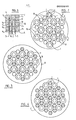
- Figures 2, 3 and 4 show in plan the three plates of an anchoring device for a cable with thirty seven strands.
- FIG. 1 three plates A, B, C are superimposed for anchoring the strands of a cable of which only the strands 1, 2 and 3 are shown.
- the strand 1 engaged in the drilling a 1 of the plate A is anchored in the orifice d 1 located on the upper face of this plate
- the strand 2 crosses the wells a 2 and b 2 to be anchored in the orifice e 2 to the upper face of the plate B.
- the strand 3 passes through the holes a 31 b 3 and c 3 to be anchored in the orifice f 3 on the upper face of the plate C.
- the thirty-seven-strand cable consists of a central strand I, a first layer II of six strands, a second layer III of twelve strands, and finally a peripheral layer IV of ten- eight strands.
- the plate A In the plate A is anchored the central strand I, six strands of layer III and six of layer IV, or thirteen strands.
- plate B In plate B are anchored three strands of layer II, three strands of layer III and six of layer IV, ie twelve strands.
- plate C three strands of layer II, three of layer III and six of layer IV are also anchored.
- the plates B and C are identical but, in service, offset by 60 ° around their common axis. It will also be noted that between the anchors arranged at the three vertices of an equilateral triangle is located, in the center thereof, a passage borehole.
- each anchoring hole ( Figure 2) a strand 1 can be maintained by three keys h which surround it, the assembly of which, in known manner, forms a truncated cone engaged in the conical anchoring orifice.
- the plate A being in place, the thirteen strands are anchored therein in the orifices d which are provided therein, then the plate B is put in place and, after tensioning, the twelve strands which pass through the orifices e are anchored therein and finally the same is done for the plate C in order to anchor the last twelve strands in the holes f.
- the superimposed anchor plates can be spaced by wedges, integral with the blocks or independent, allowing access to the gap between plates.
- This provision gives in particular the possibility, in the case of anchoring by keys, to act on these to push them into the orifices in order to block the strands after tensioning, or conversely to retain the keys to prevent them from accompanying each of the strands if one wishes to relax these. It thus becomes possible, instead of operating by stage, to carry out the tension or the simultaneous tensioning of all the strands of the same cable.
- the anchoring orifices of the plates are aligned, which makes it possible to act more easily by the edge of the plates when, moreover, they are of the same diameter and, for example circular and threaded at their periphery, are engaged in a sleeve forming a nut.
- the plates can be, in particular in the case of very large cables, divided into a certain number of elements in the form of sectors capable of being juxtaposed.
- the individual anchoring devices of the strands may not be housed in orifices formed in the thickness of the plates, but rest on these and then serve as a support for the plates or blocks located towards the 'outside.
- the anchoring device according to the invention can be used not only definitively in a structure but also as temporary anchoring, for example in tensioning devices, such as jacks.
- the invention applies to all stretched cables formed from multiple strands used in construction and public works techniques.
Abstract
Description
La présente invention concerne un dispositif d'ancrage pour un câble de précontrainte comprenant un grand nombre de brins, c'est-à-dire de fils individuels ou de torons formés chacun d'une pluralité de fils.The present invention relates to an anchoring device for a prestressing cable comprising a large number of strands, that is to say individual wires or strands each formed from a plurality of wires.
De tels câbles sont utilisés pour fournir de très importants efforts de précontrainte ou encore pour constituer des haubans de support d'ouvrage, des suspentes ou des câbles de ponts suspendus.Such cables are used to provide very large prestressing forces or even to constitute stay support stays, lines or cables for suspension bridges.
On sait que, pour pouvoir imposer à chacun des brins une tension déterminée et contrôler celle-ci, les brins sont ancrés individuellement dans le dispositif d'ancrage. A cette fin on peut utiliser le clavetage de chaque brin dans un orifice évasé qu'il traverse, ou bien on peut sceller le brin dans un tel orifice ou le munir d'un écrou ou d'une tête refoulée.It is known that, in order to be able to impose on each of the strands a determined tension and to control it, the strands are individually anchored in the anchoring device. To this end, the keying of each strand can be used in a flared orifice through which it passes, or else the strand can be sealed in such an orifice or provided with a nut or a turned head.
Lorsque les dits orifices d'ancrage sont pratiqués dans un même bloc, notamment une même plaque métallique, leur juxtaposition, et l'épaisseur de métal qu'il convient de ménager, pour la résistance de l'ensemble, entre deux orifices voisins, conduisent à des surfaces considérables. Comme il est nécessaire d'épanouir les brins à l'extrémité du câble, pour pouvoir les ancrer dans ces orifices écartés les uns des autres, la déviation ainsi imposée aux brins, spécialement à la périphérie du câble, peut, en raison de la déformation qui leur est ainsi imposée, entraîner leur affaiblissement et accroître leurs risques de rupture.When the said anchoring holes are formed in the same block, in particular the same metal plate, their juxtaposition, and the thickness of metal which it is advisable to spare, for the resistance of the assembly, between two neighboring holes, lead to considerable areas. As it is necessary to open the strands at the end of the cable, in order to be able to anchor them in these orifices separated from one another, the deviation thus imposed on the strands, especially at the periphery of the cable, may, due to the deformation imposed on them, weaken them and increase their risk of rupture.
La présente invention remédie à cet inconvénient en réduisant la déviation imposée aux brins à l'extrémité d'un tel câble pour permettre leur ancrage.The present invention overcomes this drawback by reducing the deviation imposed on the strands at the end of such a cable to allow their anchoring.
Un dispositif d'ancrage pour câble de précontrainte comprenant un grand nombre de brins est, selon l'invention, caractérisé en ce qu'il comprend au moins deux blocs plats, appelés plaques dans la suite, superposés, entre lesquels sont répartis les orifices d'ancrage, les brins ancrés dans les plaques les plus extérieures de l'ancrage traversant les plaques situées vers l'intérieur dans des forages.An anchoring device for a prestressing cable comprising a large number of strands is, according to the invention, characterized in that it comprises at least two flat blocks, hereinafter called plates, superimposed, between which the orifices d 'anchor, the strands anchored in the outermost plates of the anchor passing through the plates located inwards in boreholes.
Ainsi les forages de passage peuvent être cylindriques et répartis entre les orifices d'ancrage, ce qui permet de rapprocher ces orifices en conservant entre ceux-ci une quantité de matière suffisante pour fournir la résistance nécessaire, matière qui n'est que peu affaiblie par le forage de passage situé entre ces orifices.Thus the passage holes can be cylindrical and distributed between the anchoring holes, which allows these holes to be brought closer while keeping between them an amount of material sufficient to provide the necessary resistance, material which is only weakly weakened by passage drilling located between these orifices.
Les dessins annexés permettent de bien comprendre comment l'invention peut être mise en oeuvre.The accompanying drawings make it possible to understand clearly how the invention can be implemented.
La figure 1 est une coupe schématique d'un dispositif d'ancrage selon l'invention, coupe passant par les ancrages de trois brins situés à trois niveaux différents.Figure 1 is a schematic section of an anchoring device according to the invention, section passing through the anchors of three strands located at three different levels.
Les figures 2, 3 et 4 montrent en plan les trois plaques d'un dispositif d'ancrage destiné à un câble à trente sept brins.Figures 2, 3 and 4 show in plan the three plates of an anchoring device for a cable with thirty seven strands.
Sur la figure 1 trois plaques A, B, C sont superposées pour l'ancrage des brins d'un câble dont seuls les brins 1, 2 et 3 sont figurés. Le brin 1 engagé dans le forage a1 de la plaque A est ancré dans l'orifice d1 situé à la face supérieure de cette plaque, le brin 2 traverse les forages a2 et b2 pour être ancré dans l'orifice e2 à la face supérieure de la plaque B. Enfin le brin 3 passe par les forages a31 b3 et c3 pour être ancré dans l'orifice f3 à la face supérieure de la plaque C.In FIG. 1, three plates A, B, C are superimposed for anchoring the strands of a cable of which only the strands 1, 2 and 3 are shown. The strand 1 engaged in the drilling a 1 of the plate A is anchored in the orifice d 1 located on the upper face of this plate, the strand 2 crosses the wells a 2 and b 2 to be anchored in the orifice e 2 to the upper face of the plate B. Finally, the strand 3 passes through the holes a 31 b 3 and c 3 to be anchored in the orifice f 3 on the upper face of the plate C.
On peut se contenter de ménager dans les plaques des forages indispensables au passage de chaque brin. On peut aussi, pour un même brin, munir les plaques de forages de plus ou moins grand diamètre ou de section différente du cercle pour permettre une action de blocage ou de libération des moyens d'ancrage de ce brin dans les orifices de plaques intérieures. On peut aussi prolonger un forage de la plaque intérieure tel que a par les forages alignés b1 et cl. Ainsi toutes les plaques peuvent être initialement identiques et munies ensuite d'évasement correspondant aux orifices d'ancrage. On peut enfin, sur la face inférieure des plaques en contact avec des plaques situées au-dessous, ménager des élargissements g (figure 1) de façon que l'ancrage engagé dans l'orifice e2, en l'espèce, s'il dépasse le niveau de la plaque B, ne puisse gêner le repos de celle-ci sur la plaque A.One can be satisfied with leaving holes in the plates essential for the passage of each strand. It is also possible, for the same strand, to provide the drilling plates of greater or lesser diameter or of different cross-section of the circle to allow an action of blocking or releasing the means for anchoring this strand in the orifices of internal plates. It is also possible to extend a drilling of the inner plate such as a by the aligned bores b 1 and c l . Thus all the plates can be initially identical and then provided with flaring corresponding to the anchoring holes. It is finally possible, on the underside of the plates in contact with plates situated below, to make enlargements g (FIG. 1) so that the anchor engaged in the orifice e 2 , in this case, if exceeds the level of plate B, cannot interfere with its rest on plate A.
Dans la réalisation montrée par les figures 2, 3 et 4 le câble à trente sept brins est constitué par un brin central I, une première couche II de six brins, une seconde couche III de douze brins, enfin une couche périphérique IV de dix-huit brins.In the embodiment shown in FIGS. 2, 3 and 4, the thirty-seven-strand cable consists of a central strand I, a first layer II of six strands, a second layer III of twelve strands, and finally a peripheral layer IV of ten- eight strands.
Dans la plaque A est ancré le brin central I, six brins de la couche III et six de la couche IV, soit treize brins. Dans la plaque B sont ancrés trois brins de la couche II, trois brins de la couche III et six de la couche IV, soit douze brins. Dans la plaque C enfin, sont aussi ancrés trois brins de la couche II, trois de la couche III et six de la couche IV. Autrement dit, les plaques B et C sont identiques mais, en service, décalées de 60° autour de leur axe commun. On remarquera en outre qu'entre les ancrages disposés aux trois sommets d'un triangle équilatéral est situé, au centre de celui-ci, un forage de passage.In the plate A is anchored the central strand I, six strands of layer III and six of layer IV, or thirteen strands. In plate B are anchored three strands of layer II, three strands of layer III and six of layer IV, ie twelve strands. Finally, in plate C, three strands of layer II, three of layer III and six of layer IV are also anchored. In other words, the plates B and C are identical but, in service, offset by 60 ° around their common axis. It will also be noted that between the anchors arranged at the three vertices of an equilateral triangle is located, in the center thereof, a passage borehole.
Dans chaque orifice d'ancrage (figure 2) un brin 1 peut être maintenu par trois clavettes h qui l'entourent, dont l'ensemble, de manière connue, forme un tronc de cône engagé dans l'orifice conique d'ancrage.In each anchoring hole (Figure 2) a strand 1 can be maintained by three keys h which surround it, the assembly of which, in known manner, forms a truncated cone engaged in the conical anchoring orifice.
Sur les figures 3 et 4, pour la clarté, les forages situés au delà des ancrages ont été hachurés; ils pourraient ne pas exister. Si tous les forages sont conservés, la fabrication des plaques est facilitée; de plus, lorsque le câble doit pouvoir être remplacé par relâchement de la tension de tous les brins, il peut être avantageux de faire traverser, à tous les brins, l'ensemble des plaques afin qu'ils dépassent tous le dispositif d'ancrage.In Figures 3 and 4, for clarity, the boreholes located beyond the anchors have been hatched; they might not exist. If all the boreholes are preserved, the fabrication of the plates is facilitated; in addition, when the cable must be able to be replaced by loosening the tension of all the strands, it may be advantageous to make all the strands pass through all of the plates so that they all exceed the anchoring device.
La plaque A étant en place, on y ancre les treize brins dans les orifices d qui y sont prévus, puis on met en place la plaque B et, après mise en tension, on y ancre les douze brins qui traversent les orifices e et enfin on procède de même pour la plaque C afin d'ancrer les douze derniers brins dans les orifices f.The plate A being in place, the thirteen strands are anchored therein in the orifices d which are provided therein, then the plate B is put in place and, after tensioning, the twelve strands which pass through the orifices e are anchored therein and finally the same is done for the plate C in order to anchor the last twelve strands in the holes f.
On peut aussi, dans le cas d'ancrage par mors constitués de plusieurs clavettes, mettre en place les trois plaques en disposant les mors dans leurs logements, autour de chaque câble, et procéder ensuite à une mise en tension du câble en tirant sur l'ensemble des brins. L'ancrage s'effectue alors par autoblocage des clavettes lors du relâchement de l'action du vérin.One can also, in the case of anchoring by jaws made up of several keys, set up the three plates by arranging the jaws in their housings, around each cable, and then proceed to a tensioning of the cable by pulling on the 'set of strands. Anchoring is then carried out by self-locking of the keys when the action of the jack is released.
On peut aussi agir sur les clavettes des plaques intérieures à travers les forages, tels bl et c (voir figure 1) en particulier si ces forages ont une section en trèfle ou bien sont de diamètre suffisant pour permettre le passage d'une tige de refoulement des clavettes.One can also act on the keys of the interior plates through the holes, such b l and c (see Figure 1) in particular if these holes have a trefoil section or are of sufficient diameter to allow the passage of a rod of pushing back the keys.
Les plaques d'ancrage superposées peuvent être espacées par des cales, solidaires des blocs ou indépendantes, permettant d'accéder à l'intervalle entre plaques. Cette disposition donne notamment la possibilité, dans le cas d'ancrage par clavettes, d'agir sur celles-ci pour les enfoncer dans les orifices afin de bloquer les brins après mise en tension, ou inversement de retenir les clavettes pour les empêcher d'accompagner chacun des brins si l'on désire détendre ceux-ci. Il devient ainsi possible, au lieu d'opérer par étage, d'effectuer la tension ou la détension simultanée de tous les brins d'un même câble. On remarquera que ces opérations sont facilitées par le fait que les orifices d'ancrage des plaques sont alignés, ce qui permet d'agir plus facilement par le bord des plaques lorsqu'en outre celles-ci sont de même diamètre et, par exemple circulaires et filetées à leur périphérie, sont engagées dans une douille formant écrou. Pour des commodités d'emploi, les plaques peuvent être, en particulier dans le cas de câbles très importants, fractionnées en un certain nombre d'éléments en forme de secteurs capables d'être juxtaposés.The superimposed anchor plates can be spaced by wedges, integral with the blocks or independent, allowing access to the gap between plates. This provision gives in particular the possibility, in the case of anchoring by keys, to act on these to push them into the orifices in order to block the strands after tensioning, or conversely to retain the keys to prevent them from accompanying each of the strands if one wishes to relax these. It thus becomes possible, instead of operating by stage, to carry out the tension or the simultaneous tensioning of all the strands of the same cable. It will be noted that these operations are facilitated by the fact that the anchoring orifices of the plates are aligned, which makes it possible to act more easily by the edge of the plates when, moreover, they are of the same diameter and, for example circular and threaded at their periphery, are engaged in a sleeve forming a nut. For convenience of use, the plates can be, in particular in the case of very large cables, divided into a certain number of elements in the form of sectors capable of being juxtaposed.
Dans une autre forme de réalisation, les dispositifs d'ancrage individuel des brins peuvent ne pas être logés dans des orifices ménagés dans l'épaisseur des plaques, mais reposer sur ceux-ci et servir alors d'appui aux plaques ou blocs situés vers l'extérieur. Le dispositif d'ancrage selon l'invention peut être utilisé non seulement à titre définitif dans un ouvrage mais aussi comme ancrage provisoire, par exemple dans des appareils de mise en tension, tels que des vérins.In another embodiment, the individual anchoring devices of the strands may not be housed in orifices formed in the thickness of the plates, but rest on these and then serve as a support for the plates or blocks located towards the 'outside. The anchoring device according to the invention can be used not only definitively in a structure but also as temporary anchoring, for example in tensioning devices, such as jacks.
On remarquera qu'il est possible, lorsque ces ancrages similaires sont utilisés aux deux extrémités d'un même câble, de donner une même longueur à tous les brins, ce qui simplifie la préparation et le montage. En effet, à une des deux extrémités du câble, les brins ancrés dans la plaque extérieure seront ancrés, à l'autre extrémité, dans la plaque intérieure et vice-versa; les brins ancrés à un bout dans une plaque d'un rang déterminé vers l'intérieur sont alors ancrés, à l'autre extrémité, dans une plaque de même rang, mais cette fois à partir de l'extérieur; étant évidemment entendu, comme dans l'exemple décrit, que les brins sont répartis, à chaque extrémité, en nombre pratiquement égaux pour leur ancrage entre les plaques accolées.Note that it is possible, when these similar anchors are used at both ends of the same cable, to give the same length to all the strands, which simplifies preparation and assembly. Indeed, at one of the two ends of the cable, the strands anchored in the outer plate will be anchored, at the other end, in the inner plate and vice versa; the strands anchored at one end in a plate of a determined row towards the inside are then anchored, at the other end, in a plate of the same rank, but this time from the outside; it being obviously understood, as in the example described, that the strands are distributed, at each end, in practically equal numbers for their anchoring between the adjoining plates.
L'invention s'applique à tous les câbles tendus formés de brins multiples utilisés dans les techniques de la construction et des travaux publics.The invention applies to all stretched cables formed from multiple strands used in construction and public works techniques.
Claims (12)
Priority Applications (1)
| Application Number | Priority Date | Filing Date | Title |
|---|---|---|---|
| AT81401709T ATE11071T1 (en) | 1980-12-04 | 1981-10-27 | ANCHORING DEVICE FOR PRE-STRESSED CABLES WITH A LARGE NUMBER OF STREAKS. |
Applications Claiming Priority (2)
| Application Number | Priority Date | Filing Date | Title |
|---|---|---|---|
| FR8025757 | 1980-12-04 | ||
| FR8025757A FR2495720B1 (en) | 1980-12-04 | 1980-12-04 | ANCHORING DEVICE FOR PRE-STRESS CABLE COMPRISING A LARGE NUMBER OF STRANDS |
Publications (3)
| Publication Number | Publication Date |
|---|---|
| EP0053955A1 true EP0053955A1 (en) | 1982-06-16 |
| EP0053955B1 EP0053955B1 (en) | 1985-01-02 |
| EP0053955B2 EP0053955B2 (en) | 1990-06-20 |
Family
ID=9248661
Family Applications (1)
| Application Number | Title | Priority Date | Filing Date |
|---|---|---|---|
| EP81401709A Expired - Lifetime EP0053955B2 (en) | 1980-12-04 | 1981-10-27 | Anchoring device for prestressed cables with a great number of cords |
Country Status (10)
| Country | Link |
|---|---|
| EP (1) | EP0053955B2 (en) |
| JP (1) | JPS60482B2 (en) |
| AT (1) | ATE11071T1 (en) |
| BR (1) | BR8107674A (en) |
| CA (1) | CA1163456A (en) |
| DE (1) | DE3168080D1 (en) |
| DK (1) | DK154723C (en) |
| ES (1) | ES270020Y (en) |
| FR (1) | FR2495720B1 (en) |
| NO (1) | NO152572C (en) |
Cited By (4)
| Publication number | Priority date | Publication date | Assignee | Title |
|---|---|---|---|---|
| FR2644819A1 (en) * | 1989-03-27 | 1990-09-28 | Kajima Corp | METHOD FOR ATTACHING THE HEAD OF AN ANCHOR DEVICE |
| US5289626A (en) * | 1989-03-27 | 1994-03-01 | Kajima Corporation | Foundation anchor and method for securing same to a foundation |
| US6416143B1 (en) | 1999-06-09 | 2002-07-09 | Spacesaver Corporation | Mobile storage system |
| US20150300452A1 (en) * | 2014-04-22 | 2015-10-22 | Richard V. Campbell | Advanced Stranded Cable Termination Methods and Designs |
Families Citing this family (2)
| Publication number | Priority date | Publication date | Assignee | Title |
|---|---|---|---|---|
| DE3838069C2 (en) * | 1988-11-10 | 1995-12-14 | Hochtief Ag Hoch Tiefbauten | Transportable reinforcement unit that can be concreted in for prestressing reinforced concrete structures |
| CN107724236B (en) * | 2017-10-24 | 2022-05-03 | 长江水利委员会长江科学院 | Suspension bridge tunnel anchor combined anchorage and construction method |
Citations (3)
| Publication number | Priority date | Publication date | Assignee | Title |
|---|---|---|---|---|
| GB794561A (en) * | 1953-10-15 | 1958-05-07 | Ernst Braunbock | Improvements in or relating to prestressed concrete |
| US3658296A (en) * | 1970-09-24 | 1972-04-25 | Lawrence R Yegge | System for post-tensioning and anchoring prestressing tendons |
| CH534786A (en) * | 1971-10-21 | 1973-03-15 | Brandestini Antonio | Device for tensioning and anchoring wires or strands |
-
1980
- 1980-12-04 FR FR8025757A patent/FR2495720B1/en not_active Expired
-
1981
- 1981-10-27 DE DE8181401709T patent/DE3168080D1/en not_active Expired
- 1981-10-27 AT AT81401709T patent/ATE11071T1/en not_active IP Right Cessation
- 1981-10-27 EP EP81401709A patent/EP0053955B2/en not_active Expired - Lifetime
- 1981-11-15 BR BR8107674A patent/BR8107674A/en unknown
- 1981-11-27 ES ES1981270020U patent/ES270020Y/en not_active Expired
- 1981-12-01 NO NO814103A patent/NO152572C/en unknown
- 1981-12-02 CA CA000391365A patent/CA1163456A/en not_active Expired
- 1981-12-03 DK DK536181A patent/DK154723C/en not_active IP Right Cessation
- 1981-12-03 JP JP56195099A patent/JPS60482B2/en not_active Expired
Patent Citations (3)
| Publication number | Priority date | Publication date | Assignee | Title |
|---|---|---|---|---|
| GB794561A (en) * | 1953-10-15 | 1958-05-07 | Ernst Braunbock | Improvements in or relating to prestressed concrete |
| US3658296A (en) * | 1970-09-24 | 1972-04-25 | Lawrence R Yegge | System for post-tensioning and anchoring prestressing tendons |
| CH534786A (en) * | 1971-10-21 | 1973-03-15 | Brandestini Antonio | Device for tensioning and anchoring wires or strands |
Cited By (5)
| Publication number | Priority date | Publication date | Assignee | Title |
|---|---|---|---|---|
| FR2644819A1 (en) * | 1989-03-27 | 1990-09-28 | Kajima Corp | METHOD FOR ATTACHING THE HEAD OF AN ANCHOR DEVICE |
| US5289626A (en) * | 1989-03-27 | 1994-03-01 | Kajima Corporation | Foundation anchor and method for securing same to a foundation |
| US6416143B1 (en) | 1999-06-09 | 2002-07-09 | Spacesaver Corporation | Mobile storage system |
| US20150300452A1 (en) * | 2014-04-22 | 2015-10-22 | Richard V. Campbell | Advanced Stranded Cable Termination Methods and Designs |
| US10578191B2 (en) * | 2014-04-22 | 2020-03-03 | Bright Technologies, Llc | Advanced stranded cable termination methods and designs |
Also Published As
| Publication number | Publication date |
|---|---|
| EP0053955B2 (en) | 1990-06-20 |
| DK154723B (en) | 1988-12-12 |
| DK154723C (en) | 1989-06-05 |
| NO152572B (en) | 1985-07-08 |
| NO152572C (en) | 1985-10-16 |
| ES270020Y (en) | 1984-02-01 |
| CA1163456A (en) | 1984-03-13 |
| ATE11071T1 (en) | 1985-01-15 |
| JPS57123302A (en) | 1982-07-31 |
| DK536181A (en) | 1982-06-05 |
| BR8107674A (en) | 1982-08-24 |
| FR2495720A1 (en) | 1982-06-11 |
| DE3168080D1 (en) | 1985-02-14 |
| ES270020U (en) | 1983-07-16 |
| EP0053955B1 (en) | 1985-01-02 |
| FR2495720B1 (en) | 1985-09-27 |
| JPS60482B2 (en) | 1985-01-08 |
| NO814103L (en) | 1982-06-07 |
Similar Documents
| Publication | Publication Date | Title |
|---|---|---|
| EP1131512B1 (en) | Anchoring device for fixing a structural cable to a building element | |
| EP1144760B1 (en) | Fixing device and method between a structural element and a suspension cable | |
| EP0716325B1 (en) | Splicebox for a fibre optical cable | |
| EP0053955B1 (en) | Anchoring device for prestressed cables with a great number of cords | |
| EP0639741A1 (en) | Heat exchanger with holding means of anti-vibration bars inserted between the bundle tubes | |
| CA2127563A1 (en) | Hoisting cable | |
| EP2007947A1 (en) | Strand guide device | |
| CA2340010C (en) | Single-piece part for making a cable anchoring jaw, and method for making such a jaw | |
| FR2589457A1 (en) | AXIAL SHORTENING WINDING COIL | |
| EP1065317B1 (en) | Cable suspension for a suspension bridge | |
| EP0465303B1 (en) | Improvements in cable-stayed bridges, especially in their cables and pillars | |
| EP0565429B1 (en) | Means for anchoring to the ground an object like a road-sign or street furniture | |
| EP4116499A1 (en) | Modular foundation made of concrete | |
| EP0123622A2 (en) | Anchoring device for a prestressing cable | |
| CA2290851C (en) | Actuator with a piezoelectric or electrostrictive laser-medium | |
| EP0046703A2 (en) | Automatic means for connecting two lapped bridge elements, and bridge element comprising the same | |
| EP0030492B1 (en) | Process and device for aligning two cylindrical sections to be assembled abuttingly | |
| FR2741097A1 (en) | Pre=stressed cable anchoring system, esp. for flat cables, used e.g. in concrete road bridges, etc. | |
| WO1999067549A1 (en) | Anchoring jaw and strand anchoring device | |
| FR3070048B1 (en) | DEVICE FOR SUPPORTING THE SPLICING OF A METAL CABLE, ESPECIALLY FOR MECHANICAL RESTRAINT CABLES | |
| CH696037A5 (en) | Cables connecting device for constructing structure, has force transmission unit with electrical insulation unit disposed between force transmission ring and sleeve such that strands of cables are insulated electrically from each other | |
| WO1998034137A1 (en) | Mechanical splice for crimping optical fibre | |
| FR3121456A1 (en) | METHOD FOR REMOVING A REINFORCEMENT FROM A STRUCTURAL CABLE AND ASSOCIATED SYSTEM | |
| FR2614915A1 (en) | Improvements to devices for connecting prestressing cables together | |
| FR2567946A1 (en) | Improvements to methods and devices for locally deflecting the prestressing reinforcement |
Legal Events
| Date | Code | Title | Description |
|---|---|---|---|
| PUAI | Public reference made under article 153(3) epc to a published international application that has entered the european phase |
Free format text: ORIGINAL CODE: 0009012 |
|
| AK | Designated contracting states |
Designated state(s): AT BE CH DE GB IT LU NL SE |
|
| 17P | Request for examination filed |
Effective date: 19820601 |
|
| ITF | It: translation for a ep patent filed |
Owner name: STUDIO TORTA SOCIETA' SEMPLICE |
|
| GRAA | (expected) grant |
Free format text: ORIGINAL CODE: 0009210 |
|
| AK | Designated contracting states |
Designated state(s): AT BE CH DE GB IT LI LU NL SE |
|
| PG25 | Lapsed in a contracting state [announced via postgrant information from national office to epo] |
Ref country code: SE Effective date: 19850102 |
|
| REF | Corresponds to: |
Ref document number: 11071 Country of ref document: AT Date of ref document: 19850115 Kind code of ref document: T |
|
| REF | Corresponds to: |
Ref document number: 3168080 Country of ref document: DE Date of ref document: 19850214 |
|
| PLBI | Opposition filed |
Free format text: ORIGINAL CODE: 0009260 |
|
| PG25 | Lapsed in a contracting state [announced via postgrant information from national office to epo] |
Ref country code: LU Free format text: LAPSE BECAUSE OF NON-PAYMENT OF DUE FEES Effective date: 19851031 |
|
| 26 | Opposition filed |
Opponent name: SUSPA SPANNBETON GMBH Effective date: 19851002 |
|
| NLR1 | Nl: opposition has been filed with the epo |
Opponent name: SUSPA SPANNBETON GMBH |
|
| PUAH | Patent maintained in amended form |
Free format text: ORIGINAL CODE: 0009272 |
|
| STAA | Information on the status of an ep patent application or granted ep patent |
Free format text: STATUS: PATENT MAINTAINED AS AMENDED |
|
| 27A | Patent maintained in amended form |
Effective date: 19900620 |
|
| AK | Designated contracting states |
Kind code of ref document: B2 Designated state(s): AT BE CH DE GB IT LU NL SE |
|
| NLR2 | Nl: decision of opposition | ||
| ITF | It: translation for a ep patent filed |
Owner name: STUDIO TORTA SOCIETA' SEMPLICE |
|
| NLR3 | Nl: receipt of modified translations in the netherlands language after an opposition procedure | ||
| ITTA | It: last paid annual fee | ||
| PGFP | Annual fee paid to national office [announced via postgrant information from national office to epo] |
Ref country code: BE Payment date: 19930920 Year of fee payment: 13 |
|
| PGFP | Annual fee paid to national office [announced via postgrant information from national office to epo] |
Ref country code: NL Payment date: 19931031 Year of fee payment: 13 Ref country code: AT Payment date: 19931031 Year of fee payment: 13 |
|
| PG25 | Lapsed in a contracting state [announced via postgrant information from national office to epo] |
Ref country code: AT Effective date: 19941027 |
|
| PG25 | Lapsed in a contracting state [announced via postgrant information from national office to epo] |
Ref country code: BE Effective date: 19941031 |
|
| BERE | Be: lapsed |
Owner name: FREYSSINET INTERNATIONAL (STUP) Effective date: 19941031 |
|
| PG25 | Lapsed in a contracting state [announced via postgrant information from national office to epo] |
Ref country code: NL Effective date: 19950501 |
|
| NLV4 | Nl: lapsed or anulled due to non-payment of the annual fee | ||
| PGFP | Annual fee paid to national office [announced via postgrant information from national office to epo] |
Ref country code: GB Payment date: 19971022 Year of fee payment: 17 |
|
| PGFP | Annual fee paid to national office [announced via postgrant information from national office to epo] |
Ref country code: DE Payment date: 19971023 Year of fee payment: 17 |
|
| PGFP | Annual fee paid to national office [announced via postgrant information from national office to epo] |
Ref country code: CH Payment date: 19971028 Year of fee payment: 17 |
|
| PG25 | Lapsed in a contracting state [announced via postgrant information from national office to epo] |
Ref country code: GB Free format text: LAPSE BECAUSE OF NON-PAYMENT OF DUE FEES Effective date: 19981027 |
|
| PG25 | Lapsed in a contracting state [announced via postgrant information from national office to epo] |
Ref country code: LI Free format text: LAPSE BECAUSE OF NON-PAYMENT OF DUE FEES Effective date: 19981031 Ref country code: CH Free format text: LAPSE BECAUSE OF NON-PAYMENT OF DUE FEES Effective date: 19981031 |
|
| REG | Reference to a national code |
Ref country code: CH Ref legal event code: PL |
|
| GBPC | Gb: european patent ceased through non-payment of renewal fee |
Effective date: 19981027 |
|
| PG25 | Lapsed in a contracting state [announced via postgrant information from national office to epo] |
Ref country code: DE Free format text: LAPSE BECAUSE OF NON-PAYMENT OF DUE FEES Effective date: 19990803 |