EP0056579A1 - Verfahren zur Herstellung eines Fahrzeugreifens, insbesondere für Zweiradfahrzeuge wie Fahrräder oder Rollstühle - Google Patents
Verfahren zur Herstellung eines Fahrzeugreifens, insbesondere für Zweiradfahrzeuge wie Fahrräder oder Rollstühle Download PDFInfo
- Publication number
- EP0056579A1 EP0056579A1 EP82100043A EP82100043A EP0056579A1 EP 0056579 A1 EP0056579 A1 EP 0056579A1 EP 82100043 A EP82100043 A EP 82100043A EP 82100043 A EP82100043 A EP 82100043A EP 0056579 A1 EP0056579 A1 EP 0056579A1
- Authority
- EP
- European Patent Office
- Prior art keywords
- tire
- tread
- tires
- foot
- rim
- Prior art date
- Legal status (The legal status is an assumption and is not a legal conclusion. Google has not performed a legal analysis and makes no representation as to the accuracy of the status listed.)
- Granted
Links
Images

Classifications
-
- B—PERFORMING OPERATIONS; TRANSPORTING
- B29—WORKING OF PLASTICS; WORKING OF SUBSTANCES IN A PLASTIC STATE IN GENERAL
- B29D—PRODUCING PARTICULAR ARTICLES FROM PLASTICS OR FROM SUBSTANCES IN A PLASTIC STATE
- B29D30/00—Producing pneumatic or solid tyres or parts thereof
- B29D30/02—Solid tyres ; Moulds therefor
-
- B—PERFORMING OPERATIONS; TRANSPORTING
- B60—VEHICLES IN GENERAL
- B60C—VEHICLE TYRES; TYRE INFLATION; TYRE CHANGING; CONNECTING VALVES TO INFLATABLE ELASTIC BODIES IN GENERAL; DEVICES OR ARRANGEMENTS RELATED TO TYRES
- B60C7/00—Non-inflatable or solid tyres
- B60C7/10—Non-inflatable or solid tyres characterised by means for increasing resiliency
- B60C7/12—Non-inflatable or solid tyres characterised by means for increasing resiliency using enclosed chambers, e.g. gas-filled
-
- B—PERFORMING OPERATIONS; TRANSPORTING
- B60—VEHICLES IN GENERAL
- B60C—VEHICLE TYRES; TYRE INFLATION; TYRE CHANGING; CONNECTING VALVES TO INFLATABLE ELASTIC BODIES IN GENERAL; DEVICES OR ARRANGEMENTS RELATED TO TYRES
- B60C7/00—Non-inflatable or solid tyres
- B60C7/24—Non-inflatable or solid tyres characterised by means for securing tyres on rim or wheel body
-
- Y—GENERAL TAGGING OF NEW TECHNOLOGICAL DEVELOPMENTS; GENERAL TAGGING OF CROSS-SECTIONAL TECHNOLOGIES SPANNING OVER SEVERAL SECTIONS OF THE IPC; TECHNICAL SUBJECTS COVERED BY FORMER USPC CROSS-REFERENCE ART COLLECTIONS [XRACs] AND DIGESTS
- Y10—TECHNICAL SUBJECTS COVERED BY FORMER USPC
- Y10T—TECHNICAL SUBJECTS COVERED BY FORMER US CLASSIFICATION
- Y10T152/00—Resilient tires and wheels
- Y10T152/10—Tires, resilient
- Y10T152/10279—Cushion
- Y10T152/10378—Casing enclosed core
- Y10T152/10387—Separate core
- Y10T152/10396—Removable
- Y10T152/1045—Integral structure
Definitions
- the invention relates to puncture-proof vehicle tires, primarily for slow-moving vehicles, in particular for two-wheeled vehicles such as bicycles or wheelchairs.
- the tires which consist essentially of a uniform material, have a tread that is thickened in relation to the side walls, a circumferential cavity between the tread and the tire foot and a circumferential plastic reinforcement in the tire foot.
- the main element of the usual pneumatic tires for vehicles is the carcass.
- this is a hollow body in the form of a torus made of vulcanized rubber, which contains reinforcing elements (textile cord) that can be subjected to tensile stress.
- the hollow body is filled with air under excess pressure. Its side walls are under tensile stress.
- the weight of the vehicle counteracts this tension and partially cancels it. If such a tire leaks and loses its internal pressure, then the compressive stress generated by the vehicle weight prevails. The tire loses its shape and is unusable in practice.
- the object of the invention is to provide a light tire predominantly for slow-moving vehicles, in particular two-wheeled vehicles, which does not lose its load-bearing capacity even with minor damage (e.g. needle puncture) and nevertheless has good suspension properties. It is also desirable to use a uniform material in order to be able to use modern mass production processes (extrusion of the cross section with subsequent cutting and composition). It is also an object of the invention to ensure the press fit of the tires on the rim by means of suitable measures.
- the tires are constructed from a continuous tire flow, the side walls and the tread, which consist of one another and consist of uniform material, with a circumferential cavity between the tread and tire flow and the tire foot containing a circumferential reinforcement made of plastic, the tires are securely pressed onto the rim.
- the tread is strongly convex radially outwards, its thickness increasing towards the zenith, so that the moment of inertia of the tread is at least 6 times greater than that of the side walls.
- the tread of the tires can be smooth or provided with profiles, preferably they have profiles running in the running direction over the entire circumference of the tire.
- the circumferential cavity between the tread and the foot of the tire which significantly influences the suspension behavior of the tire, can in principle have any suitable shape.
- the shape of the hollow space chosen so that it corresponds approximately to the outer shape of the tires.
- the cavity is particularly preferably approximately elliptical, bell-shaped or wedge-shaped (cf. FIGS. 1-3).
- the tires are indented in the tire foot at the transition of the side walls, so that the side walls are supported by the rim flange.
- the shape of the tire foot itself is adapted to the rim contour. This, together with the all-round plastic reinforcement in the tire base, ensures that the tires are securely pressed onto the rim.
- the plastic reinforcement generally has a band-shaped, approximately rectangular cross-section (see FIGS. 1 and 2).
- the plastic reinforcement is preferably oriented parallel to the bevelled rim and can then e.g. have an angular cross section (see FIG. 3).
- the tires are expediently first produced with a suitable recess in the tire foot, into which the plastic reinforcement is then introduced.
- the tires are produced particularly advantageously and economically by extrusion of corresponding tread bodies and subsequent vulcanization.
- the vulcanization can take place continuously, for example by ultra-high frequency.
- the extruded and vulcanized treads are cut to the length required for the desired tire circumference and their end faces are firmly joined together. It is therefore not necessary to have a special, expensive form of vulcanization available for every tire diameter.
- a profile can be embossed into the tread of the extruded longitudinal profiles before vulcanization, which may improve the grip of the tire.
- the prefabricated tire is pushed over the rim flange.
- Tire mounting is easy because the circumferential preload only needs to be 0.5 to 1%.
- the plastic reinforcement is preferably introduced into the recess in the tire foot only after the tire has been manufactured and mounted on the rim.
- a liquid, reactive plastic mixture is pressed into the recess and cured via injection channels in the rim.
- Plastic mixtures with reaction times of about 10 seconds are preferred. After curing, there is a perfect positive connection for the transmission of the drive and side forces, so that the forces of the vehicle are safely transmitted to the resilient side walls and via the tread to the ground.
- the tires have good concentricity and high lateral stability. Even at higher speeds, centrifugal forces are unable to detach the tires from the rim.
- the tires are insensitive to cut and nail damage because there is no compressed air as a suspension element that can escape. They are particularly suitable for medical elevators or two-wheel vehicles.
- Another object of the invention is thus a method for the production of vehicle tires, characterized in that a tread body corresponding to the desired tire cross section is produced by extrusion, which has a recess in the tire foot for receiving the plastic reinforcement, the extruded profile is vulcanized and is mounted on the rim and then a reactive plastic mixture is introduced into the recess in the tire foot and cured.
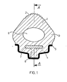
- Fig. 1 an extruded tire on the rim is shown in cross section.
- the one at the zenith The maximum thickness of the tread (1) with profiles (2) passes continuously into the side wall (3), which is followed by the circumferential tire foot (4), which is matched to the rim contour (5).
- the elliptical cavity (6) serves to ensure the spring comfort of the tire.
- the recess (7) is filled with a quick-curing plastic mixture via the two injection channels (8).
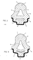
- Figure 2 shows a cross section through a tire with tread (1), profiles (2), tire foot (4) with recess (7), rim (5) and injection channel (8).
- the outer contour line (9) here runs in an arc to the rim flange. Accordingly, the cavity (6) between the tread (1) and the tire foot (4) is bell-shaped, so that the tire has a predetermined deflection characteristic.
- Figure 3 shows a cross section through a similar tire as in Figure 2 with tread (1), profiles (2), side wall (3) with contour line (9), tire foot (4), rim (5) and injection channel (8).
- the recess (7) in the tire foot (4) runs parallel to the rim slope and therefore has the shape of an angle. Accordingly, the cavity (6) is wedge-shaped.
- Figure 4 shows a longitudinal section through the tire of Figure 1 along A - A with tread (1), cavity (6), recess (7) and the injection channels (8) opening therein.
- the tires of the invention can be made from any natural or synthetic rubber, the vulcanizate values of which have a Shore A hardness of 45-80 and a tension value of 3.0 to 9.0 MPa at 300% elongation. Natural rubber, styrene-butadiene rubber, polybutadiene and ethylene / propylene terpolymer rubber are particularly suitable.
- the weight of the tire is comparable to that of normal pneumatic tires.
- the tires can be made with the following rubber compound, for example.
- any reactive, hardenable plastic mixture can be used for the plastic reinforcement in the tire base.
- the reinforcement preferably consists of a polyurethane. It can e.g. with the following two recipes.
- NCO prepolymers based on adipic acid esters BBG and C 4 polyethers (molecular weight between 1000 and 5000) and aromatic isocyanates, in the first case reacted with aromatic or aliphatic di- or polyfunctional amines.
Abstract
Description
- Die Erfindung betriff pannensichere Fahrzeugreifen, vorwiegend für langsamfahrende Fahrzeuge, insbesondere für Zweiradfahrzeuge wie Fahrräder oder Rollstühle. Die im wesentlichen aus einheitlichem Material bestehenden Reifen besitzen eine gegenüber den Seitenwänden verdickte Lauffläche, einen umlaufenden Hohlraum zwischen Lauffläche und Reifenfuß und eine umlaufende Kunststoffverstärkung im Reifenfuß.
- Das tragende Element der üblichen Luftreifen für Fahrzeuge ist die Karkasse. Dies ist im Prinzip ein Hohlkörper in Form eines Torus aus vulkanisiertem Kautschuk, der auf Zug beanspruchbare Verstärkungselemente (Textilcord) enthält. Der Hohlkörper ist mi Luft unter Überdruck gefüllt. Seine Seitenwände stehen unter Zugspannungen. Das Gewicht des Fahrzeuges wirkt dieser Zugspannung entgegen und hebt sie teilweise auf. Wird ein solcher Reifen undicht und verliert seinen Innendruck, dann überwiegt die durch das Fahrzeuggewicht erzeugte Druckspannung. Der Reifen verliert seine Form und ist in der Praxis unbrauchbar.
- Massive Reifen, in denen keine Druckluft als Federelement enthalten ist (Vollgummireifen), haben diesen Nachteil.nicht. Dafür ist ihre Masse sehr groß. Es bildet sich beim Abrollen ein hoher Rollwiderstand, der bei höheren Geschwindigkeiten zu einem Hitzestau führt.
- Aus der DE-OS 2 460 051 sind pannensichere Zweiradreifen mit durchgehendem Reifenfuß bekannt, bei denen z.B. sinusförmige Aushöhlungen an den Seitenwänden angebracht sind, um die Masse des Reifen zu reduzieren. Durch die Aushöhlungen ergibt sich ein segmentartiger Aufbau der Reifen bzw. die Ausbildung von Verstärkungsteilen zwischen Lauffläche und Reifenfuß, wodurch die notwendigen Federungseigenschaften gewährleistet sind. In der Regel werden solche Reifen durch einfache Vorspannung auf der Felge montiert, da bei einem durchgehenden Reifenfuß das Einbringen von üblichen Stahlverstärkungen nicht möglich ist. Versuche mit solchen Reifen haben allerdings gezeigt, daß diese nicht in allen Fällen für Zweiräder oder Rollstühle geeignet sind. Bei Zweirädern können sich solche Reifen bei einer Kurvenfahrt oder durch Zentrifugalkraft und bei Rollstühlen beim Drehen auf der Stelle von der Felge lösen.
- Darüber hinaus werden alle heutigen Reifenformen einschließlich normaler Luftreifen in üblichen Vulkanisierformen hergestellt, d.h. man benötigt für jede einzelne Reifendimension eine spezielle Vulkanisierform. Außerdem ist bei den bekannten pannensicheren Zweiradreifen das Gewicht i.a. wesentlich höher als das eines normalen Luftreifens.
- Aufgabe der Erfindung ist es, einen leichten Reifen vorwiegend für langsamfahrend Fahrzeuge, insbesondere Zweiradfahrzeuge anzugeben, der nicht schon bei kleineren Beschädigungen (z.B. Nadeleinstich) seine Tragfähigkeit verliert und trotzdem gute Federungseigenschaften besitzt. Weiter ist die Verwendung eines einheitlichen Materials anzustreben, um moderne Massenfertigungsverfahren (Extrudieren des Querschnitts mit anschließender Ablängung und Zusammensetzung) einsetzen zu können. Es ist weiterhin Aufgabe der Erfindung, den Preßsitz der Reifen auf der Felge durch geeignete Maßnahmen zu gewährleisten.
- Die Aufgabe wird dadurch gelöst, daß die Reifen aus einem durchgehenden Reifenfluß, den Seitenwänden und der Lauffläche aufgebaut sind, die ineinander übergehend aus einheitlichem Material bestehen, wobei sich zwischen Lauffläche und Reifenfluß ein umlaufender Hohlraum befindet und der Reifenfuß eine umlaufende Verstärkung aus Kunststoff enthält, durch ein sicherer Preßsitz der Reifen auf der Felge erreicht wird. Die Lauffläche ist radial nach außen stark konvex gewölbt, wobei ihre Dicke zum Zenit hin zunimmt, so daß das Trägheitsmoment der Lauffläche mindestens 6 mal größer als das der Seitenwände ist.
- Gegenstand der Erfindung sind somit Fahrzeugreifen, bestehend aus ineinander übergehendem Reifenfuß, Seitenwänden und Lauffläche, dadurch gekennzeichnet, daß
- a) die Reifen einen umlaufenden Hohlraum zwischen Reifenfuß und Lauffläche enthalten,
- b) die Lauffläche bis zu ihrem Zenit hin in der Dicke zunimmt, so daß das Trägheitsmoment der Lauffläche mindestens 6 mal größer als das der Seitenwände ist und
- c) der Reifenfuß eine umlaufende Verstärkung aus Kunststoff enthält.
- Für den Fachmann ist es überraschend, daß es möglich ist, solche Reifen ohne Verstärkungsmaterial (Reifencord, Drahtkerne) herzustellen, die auf Druckluft als Federelement verzichten und trotzdem in Gewicht, Federverhalten, Rollwiderstand und festem Felgensitz gleiche Eigenschaften wie Normalreifen aufweisen.
- Die Lauffläche der Reifen kann glatt oder mit Profilen versehen sein, vorzugsweise besitzt sie in Laufrichtung über den gesamten Reifenumfang verlaufende Profile.
- Der umlaufende Hohlraum zwischen Lauffläche und Reifenfuß, der das Federungsverhalten des Reifens wesentlich mitbestimmt, kann im Prinzip jede beliebige dafür geeignete Form aufweisen. Vorzugsweise wird die Form des Hohlraumes so gewählt, daß sie ungefähr der äußeren Form der Reifen entspricht. Besonders bevorzugt ist der Hohlraum annhähernd ellipsenförmig, glockenförmig oder keilförmig ausgebildet (vgl. Figur 1 - 3).
- Die Reifen sind beim Übergang der Seitenwände in den Reifenfuß eingebuchtet, so daß die Seitenwände durch das Felgenhorn abgestützt sind. Der Reifenfuß selbst ist in seiner Form der Felgenkontur angepaßt. Dadurch wird zusammen mit der umlaufenden Kunststoffverstärkung im Reifenfuß ein sicherer Preßsitz der Reifen auf der Felge erreicht. Die Kunststoffverstärkung hat i.a. einen bandförmigen, annähernd rechteckigen Querschnitt (vgl. Figur 1 und 2). Vorzugsweise ist die Kunststoffverstärkung parallel zur Felgenschräge orientiert und kann dann z.B. einen winkelförmigen Querschnitt haben (vgl. Figur 3).
- Zweckmäßigerweise werden die Reifen zunächst mit einer geeigneten Aussparung im Reifenfuß hergestellt, in die dann die Kunststoffverstärkung eingebracht wird. Besonders vorteilhaft und wirtschaftlich stellt man die Reifen durch Extrusion entsprechender Profilkörper und anschließender Vulkanisation her. Die Vulkanisation kann kontinuierlich, z.B. durch Ultrahochfrequenz erfolgen. Die extrudierten und vulkanisierten Profile werden auf die den gewünschten Reifenumfang entsprechende Länge zugeschnitten und ihre Stirnseiten auf Stoß fest miteinander verbunden. Es ist also nicht notwendig für jeden Reifendurchmesser eine besondere teure Vulkanisationsform bereitzuhalten. In die Lauffläche der extrudierten Längsprofile kann vor der Vulkanisation durch Querwalzen ein Profil geprägt werden, welches unter Umständen die Griffigkeit des Reifen verbessert.
- Die Fertigung gegenüber den bisher üblichen Luftreifen wird vereinfacht, da wegen des einheitlichen Werkstoffes der Reifen nicht lagenweise aufgebaut werden muß. Die wirtschaftliche Ersparnis ist also groß.
- Der vorgefertigte Reifen wird über das Felgenhorn geschoben. Das Aufziehen des Reifens ist einfach, da die Vorspannung in Umfangsrichtung nur 0,5 bis 1 % betragen muß.
- Die Kunststoffverstärkung wird vorzugsweise erst nach Herstellung und Aufziehen des Reifens auf die Felge in die Aussparung im Reifenfuß eingebracht. Dazu wird über Anspritzkanäle in der Felge ein flüssiges reaktionsfähiges Kunststoffgemisch in die Aussparung eingedrückt und ausgehärtet. Bevorzugt sind Kunststoffgemische mit Reaktionszeiten von etwa 10 Sekunden. Nach der Aushärtung liegt ein einwandfreier Formschluß zur Übertragung der Antriebs- und Seitenkräfte vor, so daß die Kräfte des Fahrzeugs sicher auf die federnden Seitenwände und über die Lauffläche auf den Untergrund übertragen werden.
- Die Reifen besitzen gute Rundlaufeigenschaften und eine hohe Seitenstabilität. Auch bei höherer Geschwindigkeit auftretende Zentrifugalkräfte sind nicht in der Lage, die Reifen von der Felge zu lösen. Die Reifen sind unempfindlich gegen Schnitt- und Nagelbeschädigungen da keine Druckluft als Federungselement vorhanden ist, die entweichen kann. Sie sind besonders für Krankenfahrstühle oder Zweiradfahrzeuge geeignet.
- Ein weiterer Gegenstand der Erfindung ist somit ein Verfahren zur Herstellung von Fahrzeugreifen, dadurch gekennzeichnet, daß durch Extrusion ein dem gewünschten Reifenquerschnitt entsprechender Profilkörper hergestellt wird, der im Reifenfuß eine Aussparung zur Aufnahme der Kunststoffverstärkung besitzt, das extrudierte Profil vulkanisiert und auf die Felge aufgezogen wird und anschließend in die Aussparung im Reifenfuß eine reaktionsfähige Kunststoffmischung eingebracht und ausgehärtet wird.
- Verschiedene Ausführungsformen der erfindungsgemäßen Reifen sind in Fig. 1 - 4 dargestellt. Es zeigen:
- Fig. 1 einen Querschnitt durch einen bevorzugten Reifen, Fig. 2 und 3 Querschnitte durch zwei weitere Ausführungsformen und Fig. 4 einen Längsschnitt durch einen bevorzugten Reifen entlang der Linie A - A in Fig. 1.
- In Fig. 1 ist ein extrudierter Reifen auf der Felge im Querschnitt dargestellt. Die im Zenit vorhandene maximale Dicke der Lauffläche (1) mit Profilen (2) geht unter stetiger Verjüngerung in die Seitenwand (3) über, an die sich der umlaufende Reifenfuß (4), der auf die Felgenkontur (5) abgestimmt ist, anschließt. Der ellipsenförmige Hohlraum (6) dient dazu, den Federkomfort des Reifen zu gewährleisten. Im Reifenfuß befindet sich eine umlaufende Aussparung (7), die an 2 Stellen des Umfangs mit 2 Einspritzkanälen (8) verbunden ist. Die Aussparung (7) wird über die beiden Einspritzkanäle (8) mit einer schnellhärtenden Kunststoffmischung gefüllt.
- Figur 2 zeigt einen Querschnitt durch einen Reifen mit Lauffläche (1), Profilen (2), Reifenfuß (4) mit Aussparung (7), Felge (5) und Anspritzkanal (8). Zur Abstützung der Seitenwand (3) verläuft hier deren äußere Konturlinie (9) bogenförmig zum Felgenhorn. Dementsprechend ist der Hohlraum (6) zwischen Lauffläche (1) und Reifenfuß (4) glockenförmig ausgebildet, so daß der Reifen eine vorgegebene Einfederungskennlinie besitzt.
- Figur 3 zeigt einen Querschnitt durch einen ähnlichen Reifen wie in Figur 2 mit Lauffläche (1), Profilen (2), Seitenwand (3) mit Konturlinie (9), Reifenfuß (4), Felge (5) und Anspritzkanal (8).
- Die Aussparung (7) im Reifenfuß (4) verläuft hier jedoch parallel zur Felgenschräge und hat daher die Form eines Winkels. Dementsprechend ist der Hohlraum (6) keilförmig ausgebildet.
- Figur 4 zeigt einen Längsschnitt durch den Reifen der Figur 1 entlang A - A mit Lauffläche (1), Hohlraum (6), Aussparung (7) und die darin mündenden Anspritzkanäle (8) .
- Die Reifen der Erfindung können aus jedem beliebigen Natur- oder Synthesekautschuk hergestellt werden, dessen Vulkanisatwerte eine Shore-A-Härte von 45 - 80 und einen Spannungswert von 3,0 bis 9,0 MPa bei 300 % Dehnung aufweisen. Besonders geeignet sind Naturkautschuk, Styrolbutadienkatuschuk, Polybutadien und Ethylen/Propylen-Terpolymerisat-Kautschuk. Das Gewicht des Reifens ist dem des normalen Luftreifens vergleichbar. Die Reifen können z.B. mit der nachfolgenden Kautschukmischung hergestellt werden.

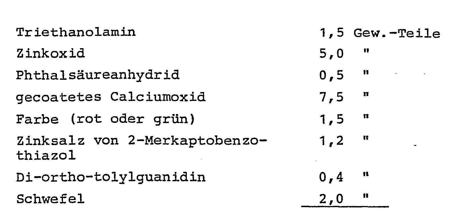

- Für die Kunststoffverstärkung im Reifenfuß kann im Prinzip jede reaktionsfähige, härtbare Kunststoffmischung verwendet werden. Vorzugsweise besteht die Verstärkung aus einem Polyurethan. Sie kann z.B. mit den beiden folgenden Rezepturen hergestellt werden.
-

-

-

-

- Es handelt sich in beiden Fällen um NCO-Prepolymere auf der Basis von Adipinsäureestern, BBG- und C4-Polyethern (Molgewicht zwischen 1000 und 5000) und aromatischen Isocyanaten, im ersten Fall mit aromatischen oder aliphatischen di- oder mehrfunktionellen Aminen umgesetzt.
Claims (5)
Applications Claiming Priority (2)
| Application Number | Priority Date | Filing Date | Title |
|---|---|---|---|
| DE19813101408 DE3101408A1 (de) | 1981-01-17 | 1981-01-17 | Fahrzeugreifen |
| DE3101408 | 1981-01-17 |
Publications (2)
| Publication Number | Publication Date |
|---|---|
| EP0056579A1 true EP0056579A1 (de) | 1982-07-28 |
| EP0056579B1 EP0056579B1 (de) | 1985-03-27 |
Family
ID=6122833
Family Applications (1)
| Application Number | Title | Priority Date | Filing Date |
|---|---|---|---|
| EP82100043A Expired EP0056579B1 (de) | 1981-01-17 | 1982-01-07 | Verfahren zur Herstellung eines Fahrzeugreifens, insbesondere für Zweiradfahrzeuge wie Fahrräder oder Rollstühle |
Country Status (5)
| Country | Link |
|---|---|
| US (1) | US4493355A (de) |
| EP (1) | EP0056579B1 (de) |
| JP (1) | JPS57140206A (de) |
| DE (2) | DE3101408A1 (de) |
| IN (1) | IN157948B (de) |
Cited By (4)
| Publication number | Priority date | Publication date | Assignee | Title |
|---|---|---|---|---|
| EP0310780A1 (de) * | 1987-09-26 | 1989-04-12 | TENTE-ROLLEN GmbH & Co. | Laufrad, insbesondere für Rollen |
| EP0403177A2 (de) * | 1989-06-08 | 1990-12-19 | The University Of Virginia Alumni Patents Foundation | Vollgummireifen für Fahrzeuge oder Karren, die wenig Unterhalt benötigen |
| WO1999055541A1 (en) * | 1998-04-23 | 1999-11-04 | Ciro Nogueira | Non-pneumatic tyre for industrial and off-the-road use and method for manufacturing it |
| US20170282648A1 (en) * | 2016-04-01 | 2017-10-05 | Fredrick Taylor | Semi-pneumatic tire |
Families Citing this family (15)
| Publication number | Priority date | Publication date | Assignee | Title |
|---|---|---|---|---|
| US4872063A (en) * | 1988-03-17 | 1989-10-03 | Optum Corporation | Method to increase scanning resolution using a synthetic aperture |
| GB8827337D0 (en) * | 1988-11-23 | 1988-12-29 | Medical Res Council | Nucleoside analogues |
| US6303060B1 (en) | 1997-10-20 | 2001-10-16 | Pacific Circle Technologies, Inc. | Method of making non-deflatable tire and wheel assembly |
| HUP9902483A3 (en) | 1999-01-05 | 2003-10-28 | New Tech Tire Llc New York | Tyre |
| US6896020B1 (en) * | 2000-06-30 | 2005-05-24 | Tbdc, Llc | Tire inflated with a plurality of balls |
| DE20104394U1 (de) * | 2001-03-06 | 2001-06-13 | Ralf Bohle Gmbh & Co Kg | Rollstuhlreifen |
| US20030024622A1 (en) * | 2001-05-04 | 2003-02-06 | Chrobak Dennis S. | Anisotropic homogeneous elastomeric closed torus tire design & method of manufacture |
| EP1820669B1 (de) * | 2006-02-15 | 2011-05-04 | C.R.F. Società Consortile per Azioni | Fahrzeugrad, insbesondere für Zweiräder |
| US7506878B2 (en) * | 2006-05-08 | 2009-03-24 | William Kurt Feick | Self-leveling tire |
| FR2997653B1 (fr) * | 2012-11-07 | 2017-12-08 | Otico | Pneumatique semi-creux a profil ameliore et organe roulant equipe de tels pneumatiques |
| CN103057356A (zh) * | 2013-01-25 | 2013-04-24 | 厦门连科工业有限公司 | 低速扁平免充气轮胎 |
| US9815331B2 (en) * | 2014-02-11 | 2017-11-14 | Xiamen Lenco Co., Ltd. | Combined tyre |
| US20160303910A1 (en) * | 2015-04-17 | 2016-10-20 | Xiamen Lenco Co.,Ltd. | Combined Tyre |
| US20180056731A1 (en) * | 2016-08-29 | 2018-03-01 | Tire Spine, LLC | Run flat tire and method of making same |
| FR3056879B1 (fr) * | 2016-09-30 | 2019-06-14 | Otico | Element pneumatique d'outil agricole comprenant une embase rigide |
Citations (7)
| Publication number | Priority date | Publication date | Assignee | Title |
|---|---|---|---|---|
| FR1361817A (fr) * | 1963-07-09 | 1964-05-22 | Perfectionnement aux bandages de roues et analogues | |
| GB1429676A (en) * | 1972-03-31 | 1976-03-24 | Pirelli | Pneumatic tyres and wheel rim assemblies and pneumatic tyres therefor |
| US3948303A (en) * | 1974-01-28 | 1976-04-06 | Patrick Ernest G | Replaceable resilient tire |
| US4033395A (en) * | 1975-03-06 | 1977-07-05 | Berg Winfred M | Continuous plastic tire body and tire |
| GB1524472A (en) * | 1975-05-06 | 1978-09-13 | Goodyear Tire & Rubber | Unitary non-inflatable moulded tyre |
| EP0010224A1 (de) * | 1978-10-18 | 1980-04-30 | Bayer Ag | Reifen für langsam fahrende Fahrzeuge |
| EP0017223A1 (de) * | 1979-04-09 | 1980-10-15 | The Firestone Tire & Rubber Company | Vollreifen für Fahrräder |
Family Cites Families (4)
| Publication number | Priority date | Publication date | Assignee | Title |
|---|---|---|---|---|
| US1466133A (en) * | 1921-09-13 | 1923-08-28 | Carl G Lundstrom | Resilient tire |
| US2345068A (en) * | 1940-08-29 | 1944-03-28 | Gen Tire & Rubber Co | Vehicle tire |
| JPS5559003A (en) * | 1978-10-27 | 1980-05-02 | Fuji Shoji Kk | Round tire |
| JPS5643010A (en) * | 1979-09-12 | 1981-04-21 | Honda Motor Co Ltd | Pneumatic tire |
-
1981
- 1981-01-17 DE DE19813101408 patent/DE3101408A1/de not_active Withdrawn
-
1982
- 1982-01-07 DE DE8282100043T patent/DE3262729D1/de not_active Expired
- 1982-01-07 EP EP82100043A patent/EP0056579B1/de not_active Expired
- 1982-01-11 US US06/338,356 patent/US4493355A/en not_active Expired - Fee Related
- 1982-01-14 JP JP57003548A patent/JPS57140206A/ja active Pending
- 1982-05-25 IN IN395/DEL/82A patent/IN157948B/en unknown
Patent Citations (7)
| Publication number | Priority date | Publication date | Assignee | Title |
|---|---|---|---|---|
| FR1361817A (fr) * | 1963-07-09 | 1964-05-22 | Perfectionnement aux bandages de roues et analogues | |
| GB1429676A (en) * | 1972-03-31 | 1976-03-24 | Pirelli | Pneumatic tyres and wheel rim assemblies and pneumatic tyres therefor |
| US3948303A (en) * | 1974-01-28 | 1976-04-06 | Patrick Ernest G | Replaceable resilient tire |
| US4033395A (en) * | 1975-03-06 | 1977-07-05 | Berg Winfred M | Continuous plastic tire body and tire |
| GB1524472A (en) * | 1975-05-06 | 1978-09-13 | Goodyear Tire & Rubber | Unitary non-inflatable moulded tyre |
| EP0010224A1 (de) * | 1978-10-18 | 1980-04-30 | Bayer Ag | Reifen für langsam fahrende Fahrzeuge |
| EP0017223A1 (de) * | 1979-04-09 | 1980-10-15 | The Firestone Tire & Rubber Company | Vollreifen für Fahrräder |
Cited By (5)
| Publication number | Priority date | Publication date | Assignee | Title |
|---|---|---|---|---|
| EP0310780A1 (de) * | 1987-09-26 | 1989-04-12 | TENTE-ROLLEN GmbH & Co. | Laufrad, insbesondere für Rollen |
| EP0403177A2 (de) * | 1989-06-08 | 1990-12-19 | The University Of Virginia Alumni Patents Foundation | Vollgummireifen für Fahrzeuge oder Karren, die wenig Unterhalt benötigen |
| EP0403177A3 (de) * | 1989-06-08 | 1991-06-12 | The University Of Virginia Alumni Patents Foundation | Vollgummireifen für Fahrzeuge oder Karren, die wenig Unterhalt benötigen |
| WO1999055541A1 (en) * | 1998-04-23 | 1999-11-04 | Ciro Nogueira | Non-pneumatic tyre for industrial and off-the-road use and method for manufacturing it |
| US20170282648A1 (en) * | 2016-04-01 | 2017-10-05 | Fredrick Taylor | Semi-pneumatic tire |
Also Published As
| Publication number | Publication date |
|---|---|
| JPS57140206A (en) | 1982-08-30 |
| DE3101408A1 (de) | 1982-09-02 |
| DE3262729D1 (en) | 1985-05-02 |
| US4493355A (en) | 1985-01-15 |
| IN157948B (de) | 1986-07-26 |
| EP0056579B1 (de) | 1985-03-27 |
Similar Documents
| Publication | Publication Date | Title |
|---|---|---|
| EP0056579A1 (de) | Verfahren zur Herstellung eines Fahrzeugreifens, insbesondere für Zweiradfahrzeuge wie Fahrräder oder Rollstühle | |
| DE19707090A1 (de) | Luftbereiftes Fahrzeugrad | |
| DE2237062A1 (de) | Luftreifen fuer fahrzeugraeder | |
| DE2545844A1 (de) | Verfahren zum vulkanisieren elastomerer gegenstaende | |
| DE2627951A1 (de) | Expandierbare blase fuer eine reifenaufbaumaschine fuer die einstufige oder zweistufige herstellung, insbesondere von radialschichtenreifen | |
| DE3102614A1 (de) | Radialreifen-karkasse und verfahren zu ihrer herstellung | |
| EP0328873B1 (de) | Luftbereiftes Fahrzeugrad | |
| EP1740398B1 (de) | Fahrzeugluftreifen mit mehrteiligem kernprofil und verfahren zu dessen herstellung | |
| EP3475070B1 (de) | Verfahren zur herstellung eines vollgummireifens und nach dem verfahren hergestellter vollgummireifen | |
| DE3311856A1 (de) | Innenschlauch fuer luftreifen sowie vorrichtung zu seiner herstellung | |
| EP0192112A2 (de) | Luftreifen mit Notlaufeigenschaften | |
| EP0076412B1 (de) | Fahrzeugreifen | |
| EP0010224A1 (de) | Reifen für langsam fahrende Fahrzeuge | |
| DE4209687A1 (de) | Reifen für ein Fahrzeug, insbesondere für ein Kraftfahrzeug sowie Verfahren zu dessen Herstellung | |
| EP0561762A1 (de) | Felgenband | |
| EP0071900A2 (de) | Gummifederreifen | |
| DE2228610A1 (de) | Verfahren und form zur herstellung gegossener luftreifen | |
| DE2821093A1 (de) | Fahrzeugluftreifen | |
| DE2208341C2 (de) | Verfahren zur Herstellung eines Luftreifens | |
| DE1480936A1 (de) | Guertelreifen | |
| EP3554930A1 (de) | Raupenkette, insbesondere gummiraupenkette | |
| DE2821041A1 (de) | Radialreifen mit verstaerkungsband | |
| DE3601316A1 (de) | Radreifeneinheit | |
| DE2151250A1 (de) | Sicherheitseinsatz fuer reifen | |
| DE4439011C1 (de) | Fahrzeugluftreifen |
Legal Events
| Date | Code | Title | Description |
|---|---|---|---|
| PUAI | Public reference made under article 153(3) epc to a published international application that has entered the european phase |
Free format text: ORIGINAL CODE: 0009012 |
|
| 17P | Request for examination filed |
Effective date: 19820107 |
|
| AK | Designated contracting states |
Designated state(s): BE DE FR GB IT NL |
|
| ITF | It: translation for a ep patent filed |
Owner name: ING. C. GREGORJ S.P.A. |
|
| GRAA | (expected) grant |
Free format text: ORIGINAL CODE: 0009210 |
|
| AK | Designated contracting states |
Designated state(s): BE DE FR GB IT NL |
|
| REF | Corresponds to: |
Ref document number: 3262729 Country of ref document: DE Date of ref document: 19850502 |
|
| ET | Fr: translation filed | ||
| PLBE | No opposition filed within time limit |
Free format text: ORIGINAL CODE: 0009261 |
|
| STAA | Information on the status of an ep patent application or granted ep patent |
Free format text: STATUS: NO OPPOSITION FILED WITHIN TIME LIMIT |
|
| 26N | No opposition filed | ||
| PGFP | Annual fee paid to national office [announced via postgrant information from national office to epo] |
Ref country code: NL Payment date: 19890131 Year of fee payment: 10 |
|
| PGFP | Annual fee paid to national office [announced via postgrant information from national office to epo] |
Ref country code: DE Payment date: 19891222 Year of fee payment: 9 |
|
| PGFP | Annual fee paid to national office [announced via postgrant information from national office to epo] |
Ref country code: FR Payment date: 19891227 Year of fee payment: 9 |
|
| ITTA | It: last paid annual fee | ||
| PGFP | Annual fee paid to national office [announced via postgrant information from national office to epo] |
Ref country code: GB Payment date: 19900131 Year of fee payment: 9 Ref country code: BE Payment date: 19900131 Year of fee payment: 9 |
|
| PG25 | Lapsed in a contracting state [announced via postgrant information from national office to epo] |
Ref country code: GB Effective date: 19910107 |
|
| PG25 | Lapsed in a contracting state [announced via postgrant information from national office to epo] |
Ref country code: BE Effective date: 19910131 |
|
| PG25 | Lapsed in a contracting state [announced via postgrant information from national office to epo] |
Ref country code: NL Effective date: 19910801 |
|
| GBPC | Gb: european patent ceased through non-payment of renewal fee | ||
| NLV4 | Nl: lapsed or anulled due to non-payment of the annual fee | ||
| PG25 | Lapsed in a contracting state [announced via postgrant information from national office to epo] |
Ref country code: FR Effective date: 19910930 |
|
| PG25 | Lapsed in a contracting state [announced via postgrant information from national office to epo] |
Ref country code: DE Effective date: 19911001 |
|
| REG | Reference to a national code |
Ref country code: FR Ref legal event code: ST |