EP0056963B2 - Polyester fiber dyeable under normal pressure and process for the production thereof - Google Patents
Polyester fiber dyeable under normal pressure and process for the production thereof Download PDFInfo
- Publication number
- EP0056963B2 EP0056963B2 EP82100289A EP82100289A EP0056963B2 EP 0056963 B2 EP0056963 B2 EP 0056963B2 EP 82100289 A EP82100289 A EP 82100289A EP 82100289 A EP82100289 A EP 82100289A EP 0056963 B2 EP0056963 B2 EP 0056963B2
- Authority
- EP
- European Patent Office
- Prior art keywords
- fiber
- spinning
- refractive index
- filaments
- temperature
- Prior art date
- Legal status (The legal status is an assumption and is not a legal conclusion. Google has not performed a legal analysis and makes no representation as to the accuracy of the status listed.)
- Expired
Links
Images


Classifications
-
- D—TEXTILES; PAPER
- D01—NATURAL OR MAN-MADE THREADS OR FIBRES; SPINNING
- D01D—MECHANICAL METHODS OR APPARATUS IN THE MANUFACTURE OF ARTIFICIAL FILAMENTS, THREADS, FIBRES, BRISTLES OR RIBBONS
- D01D5/00—Formation of filaments, threads, or the like
-
- D—TEXTILES; PAPER
- D01—NATURAL OR MAN-MADE THREADS OR FIBRES; SPINNING
- D01D—MECHANICAL METHODS OR APPARATUS IN THE MANUFACTURE OF ARTIFICIAL FILAMENTS, THREADS, FIBRES, BRISTLES OR RIBBONS
- D01D5/00—Formation of filaments, threads, or the like
- D01D5/08—Melt spinning methods
- D01D5/098—Melt spinning methods with simultaneous stretching
-
- D—TEXTILES; PAPER
- D01—NATURAL OR MAN-MADE THREADS OR FIBRES; SPINNING
- D01D—MECHANICAL METHODS OR APPARATUS IN THE MANUFACTURE OF ARTIFICIAL FILAMENTS, THREADS, FIBRES, BRISTLES OR RIBBONS
- D01D5/00—Formation of filaments, threads, or the like
- D01D5/08—Melt spinning methods
- D01D5/084—Heating filaments, threads or the like, leaving the spinnerettes
-
- D—TEXTILES; PAPER
- D01—NATURAL OR MAN-MADE THREADS OR FIBRES; SPINNING
- D01F—CHEMICAL FEATURES IN THE MANUFACTURE OF ARTIFICIAL FILAMENTS, THREADS, FIBRES, BRISTLES OR RIBBONS; APPARATUS SPECIALLY ADAPTED FOR THE MANUFACTURE OF CARBON FILAMENTS
- D01F6/00—Monocomponent artificial filaments or the like of synthetic polymers; Manufacture thereof
- D01F6/58—Monocomponent artificial filaments or the like of synthetic polymers; Manufacture thereof from homopolycondensation products
- D01F6/62—Monocomponent artificial filaments or the like of synthetic polymers; Manufacture thereof from homopolycondensation products from polyesters
Definitions
- the present invention relates to improved polyester fibers. More particularly, the invention relates to polyester fibers capable of being dyed under normal pressure and still having sufficient properties for practical use, and to a spinning process for preparing improved polyester fibers possessing improved stability involving spinning an extruded filament at high speed.
- Polyester fiber especially polyester fiber consisting essentially of polyethylene terephthalate, has many excellent properties such as strength and dimensional stability and many varied uses.
- polyethylene terephthalate fibers are poor in dyeability, and it is therefore necessary to dye them under the conditions of high temperature, e.g., about 130°C, and high pressure. Consequently, the production of such fibers suffers from the disadvantages that a special apparatus is required for dyeing.
- a copolymer of polyester with a compound having a metal sulfonate group or polyether has been considered a polyethylene terephthalate having improved dyeability.
- the dye fastness and some of the excellent properties possessed by polyethylene terephthalate inherently deteriorate in such modified polyesters, however, and it is difficult to polymerize and spin them. Consequently the improvement resulting from such chemical modification detrimentally affects inherent properties of the fiber, as well as improving dyeability, since the improvement is achieved by introducing a third component that can act as a receptacle for dyeing the polymer.
- Japanese Patent Publication (unexamined) 64113/1979 discloses a felt yarn and tow prepared by spinning at a relatively high speed of about 4,000 m/min. characterized by denier per filament, intrinsic viscosity [n], relative dyeing velocity of dispersed dye, modulus, modulus after boiled water treatment, amorphous modulus, shrinkage in boiled water, modulus at shrinking, and shrinkage.
- the Japanese Patent Publication discloses only polyster filament or tow having suitable properties making it suitable as a substitute for cellulose acetate fiber, however, i.e., it has a lower modulus and higher elongation than conventional polyester fibers. Furthermore, there is no description of dye fastness in the Japanese Patent Publication.
- United States Patent 4,134,882 discloses a polyester fiber dyeable under normal pressure and having a long period of about 300 A or more and a difference of birefringence index between that of an inner layer of fiber and that of an outer layer of fiber of less than about 10 x 10- 3 .
- a polyethylene terephthalate fiber according to the above patent is prepared by extruding polyethylene terephthalate through a specific spinnerett having capillary dimensions designed so as to produce high shear and withdrawing the extruded fiber at a speed of 5,400 to 7,200 m/min.
- the polyethylene terephthalate fiber described in the patent is dyed under normal pressure, however, it takes a long time to attain a balance dye absorption.
- the fiber does not satisfy the condition of T max (a peak temperature at peak of dynamic mechanical loss tangent measured with a frequency of 110 Hz) required for attaining a deep dye absorption under dyeing at normal pressure.
- T max of the fiber prepared according to the process described in example 28 of the above patent is 112°C, a higher value than those of the fibers of the present invention.
- the improvement in dyeability of the fiber prepared by the above patent is limited, because the dyeability (indicated by RDDR) decreases with an increasing withdrawal speed as exemplified by the examples.
- Japanese Patent Publication (unexamined) 107511/1980 discloses a process for preparing a polyethylene terephthalate fiber having a section average birefringence (An) of 90 X 10-' or more and a double structure at a section of the fiber, i.e., there is some difference in birefringence at a section of fiber between an outer layer of fiber and inner layer thereof.
- Japanese Patent Publication (unexamined) 107511/ 1980 also points out that the fiber has mechanical properties similar to that of conventional polyethylene terephthalate fiber, viz. natural crimp and good absorption of dye. Such natural crimp, however, is insufficient for practical use and, moreover, causes lower process efficiency upon subsequent processing and a lower quality of knitted and woven fabric.
- Japnese Patent Publication (unexamined) 107511/1980 not only discloses and teaches a specific structure of fiber, but also a dyeability under normal pressure, and an effect related to dye fastness.
- the fiber of the present invention which is capable of being dyed under normal pressure, cannot be prepared by the process described in the Japanese Patent Publication.
- a fiber having properties adequate for practical use can be prepared by a spinning process comprising extruding a melt of polyester and spinning at high speed in Japanese Patent Publication (examined) 3104/1960, Japanese Patent Publication (unexamined) 107511/1980, and Seni Gakkai-shi 33 T208 to T214 (1977).
- the fiber prepared by spinning at about 5,000 m/min. or more is very similar to a conventional stretched fiber. It has been clear from studies that spinning at high speed, especially 5,000 m/min. or more, causes breaking of the filament and fiber during the spinning process and lowers spinning stability, i.e., lowers operating efficiency. This tendency increases with lower filament denier and an increase in the number of filaments.
- polyester fiber had a filament denier of 0.56 dtex to 5,6 dtex and a number of filaments of 10 or more, for example, it was very difficult to spin at 6,000 m/min. or more.
- conditions of spinning such as viscosity of polymer; spinning temperature, spinning draw-ratio, and condition of cooling air in order to improve spinning stability at high speed spinning. We found that it was impossible to increase spinning stability by varying these conditions.
- Japanese Patent Publication (examined) 13156/1960 discloses a process for controlling orientation of filaments by providing a heating zone substantially contacting a nozzle. Although this process permits improvement of properties such as strength and elongation, spinning stability, especially spinning stability at high speed spinning, remains a problem.
- Japanese Patent Publication (unexamined) 151611/1979 discloses a process comprising subjecting a filament extruded from a nozzle to suction or a vacuum with an aspirator and then winding with a winding device.
- the purpose of the Japanese Patent Publication is to avoid raising the tension of a filament during spinning, which is caused by air resistance.
- a process for accumulating filaments on a conveyor net also has been known as a spun-bond process.
- an aspirator is employed instead of a godet roll or winder.
- An object of the present invention is to provide a polyester fiber consisting essentially of polyethylene terephthalate, capable of being dyed under normal pressure.
- the polyester fiber of the present invention consists essentially of polyethylene terephthalate capable of being dyed under normal pressure and having an initial modulus of more than 44 cN/dtex, a peak temperature (T max) at peak of dynamic mechanical loss tangent (tan 5) measured with a frequency of 110 Hz of 85 0 C to 110°C a peak value of the dynamic mechanical loss tangent ((tan 5) max) of 0.115 to 0.135, and a local average refractive index distributed symmetrically around the center of the cross of the fiber.
- a process for producing the fiber of the invention comprises extruding a melt of polyester, passing the extruded filaments through a heating zone provided at the surface of the nozzle and having a length of at least 5 cm and a temperature of 150°C to the melting point of the polyester, applying a vacuum with an aspirator located below the heating zone, and then winding at a speed of at least 5,000 m/min.
- polyester fiber having a specific amorphous structure could overcome the disadvantages of conventional fibers. And only a polyester fiber having a specific amorphous structure has an excellent dyeability, especially a dyeability under normal pressure, and an excellent dye fastness in addition to the suitable inherent properties of polyester fibers.
- spinning stability at high speed spinning could be improved by a specific process comprising subjecting extruded filaments to a vacuum or suction with an aspirator provided below the nozzle and spinning at specific speed.
- the fiber prepared By spinning at the specific spinning speed, the fiber prepared can have a novel microstructure and can be dyed under normal pressure. By using an aspirator, the fiber has adequate properties for practical use and good dyeability. Moreover, it has been found that when the filaments pass through a heating zone provided at the surface of the nozzle having a specific length and a specific temperature before being subjected to a vacuum, the efficiency and stability of spinning at high speed spinning increase remarkably.
- Polyesters polymerized by known processes can be employed in the present invention.
- a polyester consisting essentially of polyethylene terephthalate is employed.
- Known additives for polyesters such as a delustering agent, a stabilizer, and an antistatic agent can be added to the polyester.
- the intrinsic viscosity of the polyester used in the present invention is not limited in scope because of the fiber to be formed. In view of the desired stability of spinning and properties of the fiber, the intrinsic viscosity of the polyester preferably is in the range of 0.48 to 1.0.
- a copolymer of a polyester with a small amount of comonomer may be employed within the scope of the present invention.
- a polyester fiber of the present invention is characterized by a peak temperature (T max) at peak of dynamic mechanical loss tangent (tan 5) measured with a frequency of 110 Hz of 85 to 110°C and a peak value of dynamic mechanical loss tangent ((tan 5) max) of 0.115 to 0.135.
- T max peak temperature
- (tan 5) max) peak value of dynamic mechanical loss tangent
- a conventional polyester fiber has a T max of 120°C or more, and generally its (tan 5) max increases when the T max decreases. Consequently, a polyester fiber having the combination of dyeability, dye fastness, and heat stability has never previously been known.
- the initial modulus at 30°C preferably is in the range of 44 cN/dtex to 88 cN/dtex in order to achieve the inherent properties of polyester.
- the birefringence index ( ⁇ n) in the present invention is preferably 30x 10 -3 or more.
- the initial modulus at 30°C in the present invention is represented by a dynamic elasticity at 30°C (E'30).
- the fiber has sufficient strength and is also improved in uniformity of dye, strength, and elongation and does not have a natural crimp.
- a local average refractive index distributed symmetrically around the center of the cross section of a fiber means that the minimum value of the average refractive index, (n // min), is more than (n //(0) -10 ⁇ 10 -3 ), that (n // min) exists in the range of r/R from -0.15 to 0.15, and that the difference between n //(0.8) and n //(-0.8 ) is less than 10x 10- 3.
- Values of n //(0) , (n // min), n //(0.8) , n //(-0.8) , ⁇ (0.8-0), and An hereinbefore mentioned are measured by methods using an interference microscope discussed below (see Fig. 5).
- Crystallinity (Xc), apparent crystallite size at the (010) face (ACS), and crystal orientation at the (010) face (Co) are all related to mechanical properties of the fiber.
- the Xc is preferably in the range of 70% to 85%, more preferably 75% to 85%
- the ACS is preferably in the range of 5 nm to 7,5 nm more preferably 5,5 to 7,5 nm
- the Co is preferably in the range of 90% to 98%, more preferably 94% to 98%, so that the fiber of the present invention has suitable properties for a polyester fiber such as a strength of 2,6 cN/dtex or more, an elongation of 20% to 60%, and an initial modulus of 44 cN/dtex to 88 cN/ detex.
- the orientation angle (H) is preferably 94% or more.
- the Xc, ACS, and Co of the present invention are measured by X-ray diffraction discussed below.
- the average birefringence ( ⁇ n) of the present invention is preferably 30x 10- 3 or more so that the fiber has an initial modulus at 30°C of 44 cN/dtex to 88 cN/dtex.
- the An is preferably 110 ⁇ 10 -3 or less, more preferably 85 ⁇ 10 -3 or less.
- the initial modulus when dynamic mechanical loss tangent at 220°C (tan 5 220) is small, the initial modulus does not decrease with elevating temperature. Especially when the tan 5 220 is 0.025 or less, the decrease of initial modulus becomes remarkably small.
- the fiber of the present invention is prepared by a high speed spinning process of at least 5,000 m/min, for example at 7,000 m/min. or more, preferably 7,300 m/min. or more.
- a fiber having desirable properties is preferably prepared with good efficiency and stability of spinning at high speed spinning when cooling and solidification and dimensional transformation of polymer extruded from a nozzle are controlled by regulating conditions such as polymer viscosity, spinning temperature, conditions of the atmosphere below the nozzle, the method for cooling filaments, and the speed of spinning.
- the spinning speed is defined as that of the first godet roll or winding speed in the case of godetless process by which a cooled and solidified filament is wound after an entangling process and a lubrication treatment, if necessary.
- a high speed spinning process can be conducted stably at 5,000 m/min. or more. More preferably, a process of spinning at 7,000 m/min. or more can prepare the polyester fiber of the present invention capable of being dyed under normal pressure.
- Polyesters that can be employed in the process of the present invention are polyesters consisting essentially of polyethylene terephthalate.
- the polymers are prepared by known polymerization processes.
- a polyethylene terephthalate which is polymerized with a small amount of comonomer may also be employed.
- an extruded filament passes through a heating zone maintained at a temperature of 150°C to the melting point of the polyester, preferably 150°C to a temperature below 15°C from the melting point of the polyester, and having a length of at least 5 cm from the surface of the nozzle.
- the heating zone can be formed, for example, by providing circular heating apparatus having a suitable inside diameter depending on the arrangement of fine holes on the surface of the nozzle.
- Known heaters can be employed in the circular heating apparatus, but an electric heater is preferred in terms of efficiency.
- the heating zone can be supplied with a heated fluid in an area of 5 cm or more below the surface of the nozzle, or it can be a cylindrical tube attached to the surface of the nozzle, which in turn heats the fluid within the tube.
- the length of the heating zone must be at least 5 cm. When it is less than 5 cm, spinning cannot be carried out stably under high speed winding.
- the upper limit of the length of the heating zone is not particularly critical. A length of 100 cm or less is preferred, however, in terms of cost of equipment and performance.
- the most preferred length of the heating zone is, however, depending on spinning conditions such as a spinning temperature and denier of filament, 20 cm to 100 cm.
- the atmosphere in the heating zone can be air, nitrogen, steam, etc. Generally air is preferred.
- the temperature of the atmosphere must be 150°C to the melting point of polyester. When the temperature of the heating zone is less than 150°C, the annealing effect is insufficient and stable spinning cannot be carried out under high speed spinning. When the temperature of the heating zone is more than the melting point of the polyester, the filaments stick together and vibrate and therefore the spinning stability decreases.
- the temperature of 150°C to a temperature below 15°C from the melting point of the polyester is preferred.
- the temperature of the heating zone of the present invention means the temperature in the neighborhood of the filaments in the heating zone. The heating zone enhances the operability of a commercial process and high spinning stability and efficiency.
- an important element is that the filaments are subjected to a vacuum or suction applied by an aspirator.
- an aspirator of the present invention apparatus that can generate a stream in a direction parallel to the running filament can be employed.
- the aspirator described in Japanese Patent Publication (unexamined) 151611/1979 can be employed.
- One embodiment of an asipirator that can be used in the present invention is shown in Fig. 2.
- the filaments introduced through hole 9 are pulled by suction from the compressed fluid introduced through hole 10.
- the distance between the heating zone and the aspirator is determined by spinning conditions such as the amount of polymer extruded, the number of filaments, the temperaure of the heating zone, and the spinning speed. When it is too short, the filaments stick together at the aspirator. On the other hand, when it is too long, a high pressure and a high flux are required to obtain sufficient effect from the aspirator. Therefore, the distance between the heating zone and the aspirator is preferably 5 cm to 60 cm, more preferably 10 cm to 40 cm.
- Various fluids can be supplied to the aspirator, e.g., air, nitrogen, and steam, but generally air is preferred.
- the pressure and flux of the fluid are determined by the denier of the filament, the number of filaments, and the spinning speed. It is preferred, however, to give the filaments a velocity of more than one tenth of the spinning speed.
- the velocity that filaments are given by the aspirator is calculated from the denier of filaments passed through the aspirator and the amount of polymer extruded.
- the temperature of the fluid is preferably room temperature or higher. Fluid having an extremely low temperature probably results in inferior properties and also detrimentally affects cost.
- the fluid of the aspirator is supplied from the circumferential direction of the filament and in a direction parallel to the running filament.
- the filament leaving the aspirator is wound at a speed of at least 5,000 m/min., preferably less than 12,000 m/min., more preferably 6,000 m/min. to 10,000 m/min., and still more preferably 7,300 m/min. to 10,000 m/min.
- the spinning speed is less than 5000 m/min.
- the properties of the fiber such as strength, elongation, initial modulus, shrinkage, etc.
- An especiailly excellent fiber having no natural crimp and good dyeability under normal pressure is prepared at a spinnig speed of 7,000 m/min. or more.
- the spinning speed is over 12,000 m/min., a suitable fiber is not prepared, because filaments break easily even though other conditions are within preferred ranges.
- a conventional cooling device using cooled air can be employed between the heating zone and the aspirator, or after the aspirator in the present invention.
- the aspirator also can serve as a cooling device when a cooling device is not provided.
- a known lubrication treatment as described in Japanese Patent Publication (examined) 21925/1966
- a known entangling treatment as described in U.S. Patent 2,985,995
- the winder that can be used in the present invention can be, for example, a high speed winder described in Seni Gakkai-shi 33 No. 5, T209.
- the fiber of the present invention can be used as a filament itself. Furthermore, the fiber can be subjected to false twisting or texturizing by fluid. The fiber also can be knitted or woven alone or mixed with other fibers. The staple fiber that is made from the fiber of the present invention can be used as a spun yarn or a mixed yarn.
- the fiber of the present invention has excellent dye fastness as well as excellent dyeability under normal pressure at 100°C.
- the fiber of the present invention has a specific microstructure so that even when the fiber is heated in a process for manufacturing fabrics, the structure barely changes.
- the fiber of the present invention may be highly efficiently processed during subsequent processing. Furthermore, since the knitted and woven fabric prepared from the fiber of the present invention has high quality, the fiber of the present invention is useful for cloth.
- polyester fiber has adequate properties for practical use such as strength, elongation, Young's modulus, shrinkage, etc.
- the phase angle corresponds to the difference of the angle between the constant sinusoidal (sine wave) stress applied to a sample at a frequency and a strain sinusoidally generated in the sample.
- the dynamic mechanical loss tangent (tan 6) and the dynamic elasticity (E') can be measured by using the apparatus for measuring dynamic elasticity manufactured by Toyo Baldwin, Rheo-Vibron DDV-Ilc, at a frequency of 110 Hz, in dry air and at a temperature increasing at the rate of 10°C/min.
- tan 5 T max
- peak value of tan 6 ((tan 5) max) are given from the tan ⁇ temperature curve.
- Typical embodiments of a tan ⁇ temperature curve and an E'-temperature curve are illustrated in Fig. 3, wherein (A) represents a fiber of the present invention, (B) represents a conventional stretched fiber, (C) represents an unstretched fiber, and (D) represents a partially oriented fiber.
- the distribution of the average refractive index, observed from the side face of the fiber can be determined.
- the method can be applied to fibers having a circular cross section.
- the refractive index of fibers is characterized by a refractive index to polarized light vibrating in the direction parallel to the fiber axis (n // ) and a refractive index to polarized light vibrating in the direction perpendicular to the fiber axis (n ⁇ ).
- the fiber to be tested is immersed in a medium inert to fibers having a refractive index (n) giving a deviation of the interference fringe in the range of 0.2 to 2.0 times the wavelength by using optionally flat slide glass and cover glass.
- the fiber should be disposed so that the fiber axis is perpendicular to the optical axis of the interference microscope and the interference fringe.
- the pattern of the interference fringe is photographed and enlarged at 1,500 magnifications for analysis.
- the optical path difference R is represented by the formula: wherein n is the refractive index of the medium, n // (or n 1 ) is the refractive index between S'-S" at the fiber, t is the thickness between S'-S", A is the wavelength of the radiation used, D is the distance (corresponding to 1A) between parallel interference fringes of the background, and d is the deviation of the interference fringe by the fiber.
- the distribution of the refractive index n // (or n 1 ) of the fiber at the respective positions can be determined.
- r is the distance from the center of the fiber to the respective position
- X is 1 as the position of the periphery of the fiber, but X is a value of 0 to 1 at the other position of the fiber.
- ACS can be determined by measuring the X-ray diffraction intensity in the equatorial direction by the reflection method.
- the measurement is carried out by using an X-ray generator (RU-200PL manufactured by Rigaku Denki), a goniometer (SG-9R manufactured by Rigaku Denki) and a scintillation counter.
- the fiber sample is set in a sample holder composed of aluminum so that the fiber axis is perpendicular to the plane of the 28 axis of the diffraction meter. The thickness of the sample is adjusted to 0.5 mm.
- the X-ray generator is operated at 30 kV and 80 mA.
- the diffraction intensity is recorded from 7° to 35° of 28 at a scanning speed of 1°/min., a chart speed of 10 m/min., a time constant of 1 second with a divergent slit of 1/2°, a receiving slit of 0.3 mm, and a scattering slit of 1/2°.
- the full scale deflection of the recorder is set so that the entire diffraction curve remains on the scale and the maximum intensity value exceeds 50% of the full scale.
- polyethylene terephthalate fiber has three major reflections on the quatorial line in the range of from 17° to 26° of 28 (at faces of (100), (010), and (110)).
- ACS is determined according to the equation of Scherrer described in L. E. Alexander, X-ray diffraction, Chapter 7, published by Kagaku Dojin Schuppan.
- a base line is established by drawing a straight line between 7° and 35° of 28 on the diffraction intensity curve.
- a vertical straight line is dropped from the diffraction peak, and the mid-point between the peak and the base line is marked.
- a horizontal line passing through the mid-point is drawn on the diffraction intensity curve. If the two major reflections are sufficiently separated from each other, this line intersects shoulders of the two peaks of the curve, but if they are not sufficiently separated, the line intersects one shoulder alone. The width of the peak is measured. If the line intersects one shoulder alone, the distance between the intersecting point and the mid-point is measured and doubled. If the line intersects two shoulders, the distance between the two shoulders is measured.
- the measured value is converted to a line breadth in radians and the line breadth is corrected to the formula: wherein B is the observed value width, and b is the broadening constant in radians, which is determined by the half value width of the reflection peak of a silicon single crystal at the face (111) thereof.
- the apparent crystallite size is given by the formula: wherein K is taken as one, ⁇ is the X-ray wavelength (0.15418 mm), (3 is the corrected line width, and 8 is the Bragg angle (half of 2 ⁇ ).
- a base line is established by drawing a straight line between 7° and 35° of 26 on the diffraction intensity curve, which is derived by the same method used to measure ACS. As shown in Fig. 6, the crystalline portion and the amorphous portion are separated by drawing a straight line along the tail of the lower angle and the tail of the higher angle from the peak point positioned near the angle of 20°.
- Xc is given by an area analysis method according to the formula: E. Crystalline orientation (Co)
- the degree of crystalline orientation is measured by using an X-ray generator (for example RU-200PL manufactured by Rigaku Denk), a fiber measuring device (FS-3 manufactured by Rigaku Denki), a goniometer (SG-9 manufactured by Rigaku Denki), a scintillation counter, and a pulse height analyzer.
- an X-ray generator for example RU-200PL manufactured by Rigaku Denk
- a fiber measuring device for example RU-200PL manufactured by Rigaku Denk
- FS-3 fiber measuring device
- SG-9 manufactured by Rigaku Denki
- scintillation counter for example a scintillation counter
- a polyethylene terephthalate fiber has three major reflections on the equatorial line, the reflection at the (010) face is used in the measurement of Co.
- the 28 value of the reflection of the (010) face used is determined from the curve of the diffraction intensity in the equatorial direction.
- the X-ray generator is operated at 30 kV and 80 mA.
- the fiber sample is attached to the fiber measuring device so that filaments are parallel to one another.
- the sample thickness is 0.5 mm.
- the goniometer is set at the 28 value determined by the diffraction intensity curve in the equatorial direction. Scanning is conducted in the range of from -30° to +30° in the azimuthal direction according to a method of transmission, and at the diffraction intensity is recorded by the scintillation counter. Furthermore, the diffraction intensity at -180° and the diffraction intensity at +180° are recorded. At this measurement, the scanning speed is 4°/min., the chart speed is 10 mm/min., the time constant is 1 second, the collimeter is characterized by 2 mm ⁇ , and the receiving slit has a length. of 19 mm and a width of 3.5 mm.
- the Co value is determined from the obtained diffraction intensity curve in the azimuthal direction according to the following procedures.
- An average value of the diffraction intensity value obtained at ⁇ 180° is evaluated, and a horizontal line (a base line) is drawn to pass through the point of the average value.
- a perpendicular line is drawn to the base line from the peak, and the mid-point of the perpendicular line is determined and a horizontal line passing through the mid-point is drawn.
- the distance between two intersecting points of the horizontal line and the diffraction intensity curve is measured and the measured value is converted to an orientation angle H(°) in degrees (°).
- the degree of crystalline orientation (Co) is given by the formula:
- the dyeability is evaluated by a balanced dye absorption.
- a sample is dyed with a disperse dye (Resolin Blue FBL, Tradename of Bayer) a a dye concentration of 3% owf and a bath ratio of 1 to 50 at 100°C.
- Further dispersing agent (Disper TL) of 1 g/I was added to the dyeing solution, and then acetic acid was added to condition pH of the solution to 6.
- Dye absorption (%) is calculated as follows:
- the sample is a knitted fabric prepared by simple feeding which is scoured with Scourrol FC of 2 g/I at 60°C for 20 minutes, dried, and conditioned 65% RH at 20°C.
- the sample is dyed by the same method as that used in the evaluation of dyeability described above except the concentration of dye is 1% owf and dyeing time is 90 minutes. Further, the sample is reduced and washed with hydrosulfate of 1 g/l, sodium hydroxide of 1 g/l, and a surface active agent (Sunmol RC-700) of 1 g/I at a bath ratio of 1 to 50 at 80°C for 20 minutes.
- the samples are evaluated according to JIS-L-1044 on the light fastness, JIS-L-0849 on the friction fastness, and JIS-L-0850 on the hot pressing fastness.
- the judgment of these evaluations is given by 5 grades, from 1 for the lowest to 5 for the highest, and determined by examination with the naked eye.
- Initial Modulus is the value of the dynamic elasticity (E') at 30°C, except that of Example 14.
- Tenacity and elongation are measured using a tensile testing machine, Tensilon UTM-11-20 manufactured by Toyo Baldwin, at an initial length of 5 cm and a tensile velocity of 20 mm/min.
- Shrinkage with boiling water is given by the formula: wherein L 0 is the length of a sample under the load of 1 g/I, and L is the length of the sample under the initial load of 1 g/l after the treatment in the boiling water without the load for 30 minutes.
- the filaments extruded were cooled and solidified with a steam of air at 22°C supplied from the direction of the circumference of the fiber in the parallel direction of the running filament and then, after adding a finishing agent, the filaments were spun at a speed of 3,000 m/min. to 9,000 m/min. Finally, the fiber of 38.9 dtex/7f was prepared.
- Examples 1 to 3 in Table 1 represent the present invention; Examples 4 to 7 are comparative examples.
- Polyethylene terephthalate having an intrinsic viscosity [ ⁇ ] of 0.63 was extruded from a nozzle having 36 fine holes 0.35 mm ⁇ .
- the filaments extruded were cooled and solidified with a stream of air at 22°C supplied from one direction perpendicular to the filaments, and then the filaments were spun at 1,500 m/ min.
- the fiber of 283.3 dtex/36f prepared was stretched at a stretching temperature of 160°C. Finally the stretched fiber of 83.3 dtex/36f was prepared.
- Table 1 It can be appreciated from Table 1 that the fibers of the present invention prepared in Examples 1 to 3 have adequate mechanical properties, heat stability, dyeability under normal pressure and dye fastness. On the other hand, the fibers of Comparative Examples 4 to 8 possess inadequate properties.
- Polyethylene terephthalate having [ ⁇ ] of 0.65 was extruded from a nozzle having 24 fine holes 0.25 mmq) at a spinning temperature of 290°C by using the apparatus shown in Figure 1.
- the extruded filaments were passed through a heating cylinder provided at the surface of the nozzle having fine holes, then were subjected to suction and cooled by an aspirator provided at 20 cm from the end of the heating cylinder, further were cooled and solidified by running in air at room temperature, and then, after adding a finishing agent, were wound at predetermined speed. Finally, the fiber of 55,6 dtex/24f was prepared.
- the air temperature in the heating cylinder was 200°C.
- the air was supplied to the aspirator at a temperature of 30°C and a pressure of 4,9 x 10 4 N/m 2 and the amount thereof was 8 Nm 3 /hr.
- Table 2 The microstructure and properties of the fiber for practical use are shown in Table 2. It is clear from the table that the fibers of the present invention satisfy all properties of dyeability, mechanical properties, and heat stability.
- the extruded filaments were passed through a heating cylinder, which was provided at a surface of the nozzle having fine holes, having an inside diameter of 15 cm and a length of 20 cm, and further were subjected to suction by an aspirator provided at 20 cm from the end of the heating cylinder using air at room temperature, and a fluid pressure of 9.8 ⁇ 10 4 N/m 2 supplied in an amount of 12 Nm 3 /hr.
- the velocity of the filaments exhausted from the aspirator was about 2,000 m/min. calculated based on the denier of the filaments.
- Polyethylene terephthalate employed in Example 12 was extruded from a nozzle having 36 fine holes 0.25 mm ⁇ at a spinning temperature of 290°C and spun at a spinning speed of 7,000 m/min.
- the fiber of 83,3 dtex/36f was prepared.
- a heating cylinder having an inside diameter of 15 cm was provided at the surface of a nozzle having fine holes and an aspirator was also provided below the heating cylinder.
- the filaments were subjected to lubrication and crimping treatment before winding.
- the temperature of the atmosphere inside the heating cylinder was 200°C.
- Table 4 The results are shown in Table 4 when the length of the heating cylinder and the distance between the heating cylinder and the aspirator were changed.
- Table 4 shows that all examples except Comparative Example No. 12 have good or excellent spinning stability and dyeability, and sufficient strength and elongation for practical use.
- Polyethylene terephthalate having an inherent viscosity [n] of 0.65 was extruded from a nozzle having 24 fine holes 0.25 mm ⁇ at 290°C.
- the extruded filaments were passed through the heating cylinder, which was provided at the surface of the nozzle having fine holes, having an inside diameter of 15 cm and a length of 20 cm, then were subjected to suction and cooled by the aspirator which was provided at 20 cm below the heating cylinder, then were cooled and solidified by running in air at room temperature, and then were wound at a specified speed after a lubrication treatment. Finally the fiber of 55,6 dtex/24f was prepared.
- the temperature of air inside the heating cylinder was 200°C.
- the air was supplied to the aspirator at an air pressure of 4,9x10 4 N/m 2 and a temperature of 30°C in an amount of 8 Nm 3 /hr.
- spinning stability was excellent at a spinning speed of 4,000 m/min. to 9,000 m/min.
- the properties of the fiber prepared are shown in Table 5.
- the properties of conventional stretched fiber of 55,6 dtex/ 24f prepared at a spinning speed of 1,500 m/min., a stretching ratio of 3.0, and a stretching temperature of 60°C are also shown in the table.
- No. 1 is a comparative example outside the present invention
- Nos. 3 to 6 are preferred examples
- Nos. 4 to 6 are most preferred examples
- No. 7 is a comparative example of conventional stretched fiber. It can be understood from the table that the fibers prepared by the process of the present invention have excellent properties for practical use and excellent diability.
- microstructure of fibers Nos. 1 to 6 prepared by Example 14 were observed and are shown in Table 6.
Description
- The present invention relates to improved polyester fibers. More particularly, the invention relates to polyester fibers capable of being dyed under normal pressure and still having sufficient properties for practical use, and to a spinning process for preparing improved polyester fibers possessing improved stability involving spinning an extruded filament at high speed.
- Polyester fiber, especially polyester fiber consisting essentially of polyethylene terephthalate, has many excellent properties such as strength and dimensional stability and many varied uses. On the other hand, polyethylene terephthalate fibers are poor in dyeability, and it is therefore necessary to dye them under the conditions of high temperature, e.g., about 130°C, and high pressure. Consequently, the production of such fibers suffers from the disadvantages that a special apparatus is required for dyeing. Moreover, use of such fibers in admixture with fibers such as wool and acrylic fibers, whose physical properties deteriorate upon dyeing under high pressure and high temperature, is limited.
- Various improvements in dyeability of polyester fiber under normal pressure have been proposed. A process in which carriers are employed in dyeing, for example, is known. The process has the disadvantages, however, that specific carriers are required and a subsequent treatment with dyeing liquid is difficult.
- A copolymer of polyester with a compound having a metal sulfonate group or polyether has been considered a polyethylene terephthalate having improved dyeability. The dye fastness and some of the excellent properties possessed by polyethylene terephthalate inherently deteriorate in such modified polyesters, however, and it is difficult to polymerize and spin them. Consequently the improvement resulting from such chemical modification detrimentally affects inherent properties of the fiber, as well as improving dyeability, since the improvement is achieved by introducing a third component that can act as a receptacle for dyeing the polymer.
- An improvement in dyeability by other than chemical modification also has been proposed. Japanese Patent Publication (unexamined) 64113/1979, for example, discloses a felt yarn and tow prepared by spinning at a relatively high speed of about 4,000 m/min. characterized by denier per filament, intrinsic viscosity [n], relative dyeing velocity of dispersed dye, modulus, modulus after boiled water treatment, amorphous modulus, shrinkage in boiled water, modulus at shrinking, and shrinkage. The Japanese Patent Publication discloses only polyster filament or tow having suitable properties making it suitable as a substitute for cellulose acetate fiber, however, i.e., it has a lower modulus and higher elongation than conventional polyester fibers. Furthermore, there is no description of dye fastness in the Japanese Patent Publication.
- United States Patent 4,134,882 discloses a polyester fiber dyeable under normal pressure and having a long period of about 300 A or more and a difference of birefringence index between that of an inner layer of fiber and that of an outer layer of fiber of less than about 10 x 10-3. A polyethylene terephthalate fiber according to the above patent is prepared by extruding polyethylene terephthalate through a specific spinnerett having capillary dimensions designed so as to produce high shear and withdrawing the extruded fiber at a speed of 5,400 to 7,200 m/min. When the polyethylene terephthalate fiber described in the patent is dyed under normal pressure, however, it takes a long time to attain a balance dye absorption. The fiber does not satisfy the condition of T max (a peak temperature at peak of dynamic mechanical loss tangent measured with a frequency of 110 Hz) required for attaining a deep dye absorption under dyeing at normal pressure. T max of the fiber prepared according to the process described in example 28 of the above patent is 112°C, a higher value than those of the fibers of the present invention. Moreover, the improvement in dyeability of the fiber prepared by the above patent is limited, because the dyeability (indicated by RDDR) decreases with an increasing withdrawal speed as exemplified by the examples.
- Japanese Patent Publication (unexamined) 107511/1980 discloses a process for preparing a polyethylene terephthalate fiber having a section average birefringence (An) of 90X10-' or more and a double structure at a section of the fiber, i.e., there is some difference in birefringence at a section of fiber between an outer layer of fiber and inner layer thereof. Japanese Patent Publication (unexamined) 107511/ 1980 also points out that the fiber has mechanical properties similar to that of conventional polyethylene terephthalate fiber, viz. natural crimp and good absorption of dye. Such natural crimp, however, is insufficient for practical use and, moreover, causes lower process efficiency upon subsequent processing and a lower quality of knitted and woven fabric. Japnese Patent Publication (unexamined) 107511/1980 not only discloses and teaches a specific structure of fiber, but also a dyeability under normal pressure, and an effect related to dye fastness. Thus, the fiber of the present invention, which is capable of being dyed under normal pressure, cannot be prepared by the process described in the Japanese Patent Publication.
- It has been disclosed that a fiber having properties adequate for practical use can be prepared by a spinning process comprising extruding a melt of polyester and spinning at high speed in Japanese Patent Publication (examined) 3104/1960, Japanese Patent Publication (unexamined) 107511/1980, and Seni Gakkai-shi 33 T208 to T214 (1977). With respect to the disclosure of polyethylene terephthalate fiber in these publications, the fiber prepared by spinning at about 5,000 m/min. or more is very similar to a conventional stretched fiber. It has been clear from studies that spinning at high speed, especially 5,000 m/min. or more, causes breaking of the filament and fiber during the spinning process and lowers spinning stability, i.e., lowers operating efficiency. This tendency increases with lower filament denier and an increase in the number of filaments.
- When a polyester fiber had a filament denier of 0.56 dtex to 5,6 dtex and a number of filaments of 10 or more, for example, it was very difficult to spin at 6,000 m/min. or more. We have studied conditions of spinning such as viscosity of polymer; spinning temperature, spinning draw-ratio, and condition of cooling air in order to improve spinning stability at high speed spinning. We found that it was impossible to increase spinning stability by varying these conditions.
- On the other hand, Japanese Patent Publication (examined) 13156/1960 discloses a process for controlling orientation of filaments by providing a heating zone substantially contacting a nozzle. Although this process permits improvement of properties such as strength and elongation, spinning stability, especially spinning stability at high speed spinning, remains a problem.
- Japanese Patent Publication (unexamined) 151611/1979 discloses a process comprising subjecting a filament extruded from a nozzle to suction or a vacuum with an aspirator and then winding with a winding device. The purpose of the Japanese Patent Publication is to avoid raising the tension of a filament during spinning, which is caused by air resistance. A process for accumulating filaments on a conveyor net also has been known as a spun-bond process. In the process, an aspirator is employed instead of a godet roll or winder. These two processes do not teach an improvement in stability of spinning and prevention of breaking of fibers and filaments.
- An object of the present invention is to provide a polyester fiber consisting essentially of polyethylene terephthalate, capable of being dyed under normal pressure.
- Additional objects and advantages of the invention will be set forth in the description that follows, and in part will be obvious from the description, or may be learned by practice of the invention. The objects and advantages of the invention may be realized and attained by means of the instrumentalities and combinations particularly pointed out in the appended claims.
- To achieve the foregoing objects and in accordance with the purpose of the invention, as embodied and broadly described herein, the polyester fiber of the present invention consists essentially of polyethylene terephthalate capable of being dyed under normal pressure and having an initial modulus of more than 44 cN/dtex, a peak temperature (T max) at peak of dynamic mechanical loss tangent (tan 5) measured with a frequency of 110 Hz of 850C to 110°C a peak value of the dynamic mechanical loss tangent ((tan 5) max) of 0.115 to 0.135, and a local average refractive index distributed symmetrically around the center of the cross of the fiber.
- Further to achieve the foregoing objects and in accordance with the purpose of the invention, as embodied and broadly described herein, a process for producing the fiber of the invention comprises extruding a melt of polyester, passing the extruded filaments through a heating zone provided at the surface of the nozzle and having a length of at least 5 cm and a temperature of 150°C to the melting point of the polyester, applying a vacuum with an aspirator located below the heating zone, and then winding at a speed of at least 5,000 m/min.
- The accompanying drawings, which are incorporated in and constitute a part of this specification, illustrate the invention and, together with the description, serve to explain the principles of the invention.
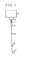
- Figure 1 is a diagram illustrating one embodiment of an apparatus employed in the process in which the numbered elements are as follows: 1, extruded filaments; 2, a spinhead with a nozzle; 3, a heating cylinder; 4, aspirator; 5, a device for a lubricating treatment; 6, a device for entangling; 7, a godet roll or winder.
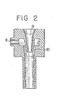
- Figure 2 is a vertical section of one embodiment of the aspirator of the present invention, in which the numbered elements are as follows: 8, a hole for supplying compressed fluid; 9, a hole for introducing filaments; 10, a hole for introducing fluid.
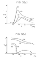
- Figures 3(a) and 3(b) are graphs illustrating a dynamic mechanical loss tangent (tan 5)-temperature (T) curve and a dynamic elasticity (E')-temperature (T) curve, respectively.
- Figure 4 is one embodiment of a pattern of interference fringe that was used to measure a distribution of refractive index (n// or n1) in the direction of a radius of a cross section of a fiber, in which (c) is a cross section of a fiber and (e) is a pattern of an interference fringe in which the numbered elements are as follows: 11, a fiber; 12, an interference fringe by a medium; 13, an interference fringe by a fiber.
- Figure 5 is a graph illustrating embodiments of distributions of refractive indices (n//) in the direction of radii of fibers of the present invention (g) and conventional fibers (f).
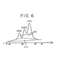
- Figure 6 is a graph of one embodiment illustrating a curve of X-ray diffraction intensity of polyethylene terephthalate fiber, in which, (h) represents a crystalline portion and (i) represents an amorphous portion.
- Reference will now be made in detail to the presently preferred embodiments of the invention, examples of which are illustrated in the accompanying drawings.
- As a result of a study on the microstructure of polyester fiber, it has been found that only a polyester fiber having a specific amorphous structure could overcome the disadvantages of conventional fibers. And only a polyester fiber having a specific amorphous structure has an excellent dyeability, especially a dyeability under normal pressure, and an excellent dye fastness in addition to the suitable inherent properties of polyester fibers.
- Furthermore, it has been found that spinning stability at high speed spinning could be improved by a specific process comprising subjecting extruded filaments to a vacuum or suction with an aspirator provided below the nozzle and spinning at specific speed.
- By spinning at the specific spinning speed, the fiber prepared can have a novel microstructure and can be dyed under normal pressure. By using an aspirator, the fiber has adequate properties for practical use and good dyeability. Moreover, it has been found that when the filaments pass through a heating zone provided at the surface of the nozzle having a specific length and a specific temperature before being subjected to a vacuum, the efficiency and stability of spinning at high speed spinning increase remarkably.
- Polyesters polymerized by known processes can be employed in the present invention. A polyester consisting essentially of polyethylene terephthalate is employed. Known additives for polyesters such as a delustering agent, a stabilizer, and an antistatic agent can be added to the polyester. The intrinsic viscosity of the polyester used in the present invention is not limited in scope because of the fiber to be formed. In view of the desired stability of spinning and properties of the fiber, the intrinsic viscosity of the polyester preferably is in the range of 0.48 to 1.0. A copolymer of a polyester with a small amount of comonomer may be employed within the scope of the present invention.
- A polyester fiber of the present invention is characterized by a peak temperature (T max) at peak of dynamic mechanical loss tangent (tan 5) measured with a frequency of 110 Hz of 85 to 110°C and a peak value of dynamic mechanical loss tangent ((tan 5) max) of 0.115 to 0.135. When the T max is more than 110°C, dyeability decreases and the fiber cannot be dyed under normal pressure. When the T max is less than 85°C, the fiber does not have adequate mechanical properties for practical use. On the other hand, when the (tan 5) max is more than 0.135, heat stability, dimensional stability, and dye fastness of the fiber decrease. When the (tan δ) max is less than 0.115, dyeability of fiber decreases and the fiber cannot be dyed under normal pressure. A conventional polyester fiber has a T max of 120°C or more, and generally its (tan 5) max increases when the T max decreases. Consequently, a polyester fiber having the combination of dyeability, dye fastness, and heat stability has never previously been known.
- In the present invention, the initial modulus at 30°C preferably is in the range of 44 cN/dtex to 88 cN/dtex in order to achieve the inherent properties of polyester. For the same reason, the birefringence index (Δn) in the present invention is preferably 30x 10-3 or more. The initial modulus at 30°C in the present invention is represented by a dynamic elasticity at 30°C (E'30). When the average refractive index (n//(0)) at the center of a fiber by polarized light having an electric field vector in the direction of the axis of a fiber is in a preferred range of 1.65 to 1.70, the fiber has a suitable elongation (20% to 60%) and dyeability. Such a fiber is desirable for use in forming cloth.
- Furthermore, when the difference of average refractive index (Δ//(0.8―0)) between average refractive index (n//(0)) at the center and refractive index at a position 0.8 times from the center of the cross section of a fiber (n//(0.8)) is within the preferred range of 10×10-3 to 80×10-3, more preferably 10×10-3 to 40×10-3, and the local average refractive index is distributed symmetrically around the center of the cross section of the fiber, the fiber has sufficient strength and is also improved in uniformity of dye, strength, and elongation and does not have a natural crimp.
- Consequently, subsequent processing can be conducted at high process efficiency, and the quality of knitted and woven fabric formed from the fiber is high.
- A local average refractive index distributed symmetrically around the center of the cross section of a fiber means that the minimum value of the average refractive index, (n// min), is more than (n//(0)-10×10-3), that (n// min) exists in the range of r/R from -0.15 to 0.15, and that the difference between n//(0.8) and n//(-0.8) is less than 10x 10-3. Values of n//(0), (n// min), n//(0.8), n//(-0.8), Δ (0.8-0), and An hereinbefore mentioned are measured by methods using an interference microscope discussed below (see Fig. 5).
- Crystallinity (Xc), apparent crystallite size at the (010) face (ACS), and crystal orientation at the (010) face (Co) are all related to mechanical properties of the fiber. In the present invention, the Xc is preferably in the range of 70% to 85%, more preferably 75% to 85%, the ACS is preferably in the range of 5 nm to 7,5 nm more preferably 5,5 to 7,5 nm, and the Co is preferably in the range of 90% to 98%, more preferably 94% to 98%, so that the fiber of the present invention has suitable properties for a polyester fiber such as a strength of 2,6 cN/dtex or more, an elongation of 20% to 60%, and an initial modulus of 44 cN/dtex to 88 cN/ detex. The orientation angle (H) is preferably 94% or more. The Xc, ACS, and Co of the present invention are measured by X-ray diffraction discussed below.
- The average birefringence (Δn) of the present invention is preferably 30x 10-3 or more so that the fiber has an initial modulus at 30°C of 44 cN/dtex to 88 cN/dtex. For purposes of heat stability, dyeability, and dye fastness, the An is preferably 110×10-3 or less, more preferably 85×10-3 or less. When the An is 110×10-3 or less, the rate of decrease of dynamic elasticity (E') at betweeen 150°C and 220°C, represented as E'220/ E'150: E'220, (E') at 220°C; E'150, (E') at 150°C, becomes 0.75 or more, i.e., the structure of the fiber is stabilized against heat, and dye fastness increases. Furthermore when the An is 85×10-3 or less, dyeability under normal pressure is greatly improved.
- In the present invention, when dynamic mechanical loss tangent at 220°C (tan 5 220) is small, the initial modulus does not decrease with elevating temperature. Especially when the tan 5 220 is 0.025 or less, the decrease of initial modulus becomes remarkably small.
- The fiber of the present invention is prepared by a high speed spinning process of at least 5,000 m/min, for example at 7,000 m/min. or more, preferably 7,300 m/min. or more. In the present invention, a fiber having desirable properties is preferably prepared with good efficiency and stability of spinning at high speed spinning when cooling and solidification and dimensional transformation of polymer extruded from a nozzle are controlled by regulating conditions such as polymer viscosity, spinning temperature, conditions of the atmosphere below the nozzle, the method for cooling filaments, and the speed of spinning. It is important to control the cooling and solidification of extruded filaments, especially since sudden cooling and solidification of extruded filaments and cooling and solidification by use of cooling air having a low temperature in a single direction crossing at a right angle to the filament, are not preferable to achieve good spinning efficiency and desirable properties. Sudden cooling and solidification at a low temperature of 0°C or less should be avoided because such cooling and solidification cause an unsymmetrical distribution of local refractive index at a cross section of the fiber and natural crimp.
- The spinning speed is defined as that of the first godet roll or winding speed in the case of godetless process by which a cooled and solidified filament is wound after an entangling process and a lubrication treatment, if necessary. According to the process of the present invention, a high speed spinning process can be conducted stably at 5,000 m/min. or more. More preferably, a process of spinning at 7,000 m/min. or more can prepare the polyester fiber of the present invention capable of being dyed under normal pressure.
- Polyesters that can be employed in the process of the present invention are polyesters consisting essentially of polyethylene terephthalate. The polymers are prepared by known polymerization processes. A polyethylene terephthalate which is polymerized with a small amount of comonomer may also be employed.
- It is preferred that an extruded filament passes through a heating zone maintained at a temperature of 150°C to the melting point of the polyester, preferably 150°C to a temperature below 15°C from the melting point of the polyester, and having a length of at least 5 cm from the surface of the nozzle.
- The heating zone can be formed, for example, by providing circular heating apparatus having a suitable inside diameter depending on the arrangement of fine holes on the surface of the nozzle. Known heaters can be employed in the circular heating apparatus, but an electric heater is preferred in terms of efficiency. Instead, the heating zone can be supplied with a heated fluid in an area of 5 cm or more below the surface of the nozzle, or it can be a cylindrical tube attached to the surface of the nozzle, which in turn heats the fluid within the tube. The length of the heating zone must be at least 5 cm. When it is less than 5 cm, spinning cannot be carried out stably under high speed winding. The upper limit of the length of the heating zone is not particularly critical. A length of 100 cm or less is preferred, however, in terms of cost of equipment and performance.
- The most preferred length of the heating zone is, however, depending on spinning conditions such as a spinning temperature and denier of filament, 20 cm to 100 cm. The atmosphere in the heating zone can be air, nitrogen, steam, etc. Generally air is preferred. The temperature of the atmosphere must be 150°C to the melting point of polyester. When the temperature of the heating zone is less than 150°C, the annealing effect is insufficient and stable spinning cannot be carried out under high speed spinning. When the temperature of the heating zone is more than the melting point of the polyester, the filaments stick together and vibrate and therefore the spinning stability decreases. The temperature of 150°C to a temperature below 15°C from the melting point of the polyester is preferred. The temperature of the heating zone of the present invention means the temperature in the neighborhood of the filaments in the heating zone. The heating zone enhances the operability of a commercial process and high spinning stability and efficiency.
- An important element is that the filaments are subjected to a vacuum or suction applied by an aspirator. As the aspirator of the present invention, apparatus that can generate a stream in a direction parallel to the running filament can be employed.
- For example, the aspirator described in Japanese Patent Publication (unexamined) 151611/1979 can be employed. One embodiment of an asipirator that can be used in the present invention is shown in Fig. 2. The filaments introduced through
hole 9 are pulled by suction from the compressed fluid introduced throughhole 10. The distance between the heating zone and the aspirator is determined by spinning conditions such as the amount of polymer extruded, the number of filaments, the temperaure of the heating zone, and the spinning speed. When it is too short, the filaments stick together at the aspirator. On the other hand, when it is too long, a high pressure and a high flux are required to obtain sufficient effect from the aspirator. Therefore, the distance between the heating zone and the aspirator is preferably 5 cm to 60 cm, more preferably 10 cm to 40 cm. - Various fluids can be supplied to the aspirator, e.g., air, nitrogen, and steam, but generally air is preferred. The pressure and flux of the fluid are determined by the denier of the filament, the number of filaments, and the spinning speed. It is preferred, however, to give the filaments a velocity of more than one tenth of the spinning speed. The velocity that filaments are given by the aspirator is calculated from the denier of filaments passed through the aspirator and the amount of polymer extruded.
- The temperature of the fluid is preferably room temperature or higher. Fluid having an extremely low temperature probably results in inferior properties and also detrimentally affects cost.
- The fluid of the aspirator is supplied from the circumferential direction of the filament and in a direction parallel to the running filament. Use of both the heating zone and the aspirator in the process of the present invention achieves high spinning efficiency and stability at high speed spinning.
- In the next step the filament leaving the aspirator is wound at a speed of at least 5,000 m/min., preferably less than 12,000 m/min., more preferably 6,000 m/min. to 10,000 m/min., and still more preferably 7,300 m/min. to 10,000 m/min.
- When the spinning speed is less than 5000 m/min., the properties of the fiber such as strength, elongation, initial modulus, shrinkage, etc., are inadequate for practical use. An especiailly excellent fiber having no natural crimp and good dyeability under normal pressure is prepared at a spinnig speed of 7,000 m/min. or more. On the other hand, when the spinning speed is over 12,000 m/min., a suitable fiber is not prepared, because filaments break easily even though other conditions are within preferred ranges.
- If necessary, a conventional cooling device using cooled air can be employed between the heating zone and the aspirator, or after the aspirator in the present invention. The aspirator also can serve as a cooling device when a cooling device is not provided.
- When the filaments are spun a known lubrication treatment (as described in Japanese Patent Publication (examined) 21925/1966), and if necessary a known entangling treatment (as described in U.S. Patent 2,985,995) can be carried out at a suitable location between the aspirator and the winder. The winder that can be used in the present invention can be, for example, a high speed winder described in Seni Gakkai-shi 33 No. 5, T209.
- The fiber of the present invention can be used as a filament itself. Furthermore, the fiber can be subjected to false twisting or texturizing by fluid. The fiber also can be knitted or woven alone or mixed with other fibers. The staple fiber that is made from the fiber of the present invention can be used as a spun yarn or a mixed yarn.
- Furthermore, the fiber of the present invention has excellent dye fastness as well as excellent dyeability under normal pressure at 100°C. The fiber of the present invention has a specific microstructure so that even when the fiber is heated in a process for manufacturing fabrics, the structure barely changes.
- The fiber of the present invention may be highly efficiently processed during subsequent processing. Furthermore, since the knitted and woven fabric prepared from the fiber of the present invention has high quality, the fiber of the present invention is useful for cloth.
- The process makes it possible to conduct stable spinning at high speed spinning of at least 5,000 m/min. to 12,000 m/min., which was extremely difficult to do previously. According to the present invention, polyester fiber has adequate properties for practical use such as strength, elongation, Young's modulus, shrinkage, etc.
- Dynamic mechanical loss tangent (tan δ) represents the fraction of the input energy lost per cycle in a dynamic tensile experiments. It is defined by tan δ=E"/E', where 5 is the phase angle between the maximum in strain and the maximum in stress, and E' is the storage modulus, and E" is the loss modulus.
- The phase angle corresponds to the difference of the angle between the constant sinusoidal (sine wave) stress applied to a sample at a frequency and a strain sinusoidally generated in the sample.
- The dynamic mechanical loss tangent (tan 6) and the dynamic elasticity (E') can be measured by using the apparatus for measuring dynamic elasticity manufactured by Toyo Baldwin, Rheo-Vibron DDV-Ilc, at a frequency of 110 Hz, in dry air and at a temperature increasing at the rate of 10°C/min.
- The peak temperature of tan 5 (T max) and the peak value of tan 6 ((tan 5) max) are given from the tan δ―temperature curve. Typical embodiments of a tan δ―temperature curve and an E'-temperature curve are illustrated in Fig. 3, wherein (A) represents a fiber of the present invention, (B) represents a conventional stretched fiber, (C) represents an unstretched fiber, and (D) represents a partially oriented fiber.
- According to the interference fringe method using a transmission quantitative type inferference microscope (for example, an interference microscope "Interphako" manufactured by Carl-Zeiss Jena Co., East Germany), the distribution of the average refractive index, observed from the side face of the fiber, can be determined. The method can be applied to fibers having a circular cross section.
- The refractive index of fibers is characterized by a refractive index to polarized light vibrating in the direction parallel to the fiber axis (n//) and a refractive index to polarized light vibrating in the direction perpendicular to the fiber axis (n┴).
- Refractive indices (n// and nl) obtained by using green radiation (wavelength À=546 mµ) are employed. The fiber to be tested is immersed in a medium inert to fibers having a refractive index (n) giving a deviation of the interference fringe in the range of 0.2 to 2.0 times the wavelength by using optionally flat slide glass and cover glass.
- The refractive index (n) of the medium is a value measured at 20°C by an Abbe refractometer using green radiation (wavelength À=546 mu).
- Several filaments are immersed in the medium so that the filaments are not in contact with one another. The fiber should be disposed so that the fiber axis is perpendicular to the optical axis of the interference microscope and the interference fringe. The pattern of the interference fringe is photographed and enlarged at 1,500 magnifications for analysis.
- Referring to Fig. 4, the optical path difference R is represented by the formula:

- From optical path differences at respective positions in the range of the center of the fiber (Ro) to the periphery of the fiber (R), the distribution of the refractive index n// (or n1) of the fiber at the respective positions can be determined. When r is the distance from the center of the fiber to the respective position, the refractive index at the center of the fiber, i.e., X=r/R=0 is defined as the average refractive index (n//(0) or n┴(0)). X is 1 as the position of the periphery of the fiber, but X is a value of 0 to 1 at the other position of the fiber.
- For example, n//(0.8) (or n┴(0.8)) represents the refractive index at the position of X=0.8. From the average refractive indices n//(0) and n┴(0), the average birefringence index (Δn) is represented as Δn=n//(0)-n┴(0). The distributions of n// of the conventional stretched fiber (f) and n// of the present of the present invention (g) is shown at Fig-. 5, wherein the horizontal axis represents the distance from the center of the fiber, i.e., X=r/R, and the vertical axis represents nil. X=0 is the center of the X=1 or X=-1 fiber; is the position at the periphery of the fiber.
- ACS can be determined by measuring the X-ray diffraction intensity in the equatorial direction by the reflection method. The measurement is carried out by using an X-ray generator (RU-200PL manufactured by Rigaku Denki), a goniometer (SG-9R manufactured by Rigaku Denki) and a scintillation counter. Cu-K a (wavelength λ=0.15 418 nm) monochromatized by a nickel filter is used for the measurement. The fiber sample is set in a sample holder composed of aluminum so that the fiber axis is perpendicular to the plane of the 28 axis of the diffraction meter. The thickness of the sample is adjusted to 0.5 mm.
- The X-ray generator is operated at 30 kV and 80 mA. The diffraction intensity is recorded from 7° to 35° of 28 at a scanning speed of 1°/min., a chart speed of 10 m/min., a time constant of 1 second with a divergent slit of 1/2°, a receiving slit of 0.3 mm, and a scattering slit of 1/2°. The full scale deflection of the recorder is set so that the entire diffraction curve remains on the scale and the maximum intensity value exceeds 50% of the full scale.
- Generally, polyethylene terephthalate fiber has three major reflections on the quatorial line in the range of from 17° to 26° of 28 (at faces of (100), (010), and (110)).
- For example, ACS is determined according to the equation of Scherrer described in L. E. Alexander, X-ray diffraction,
Chapter 7, published by Kagaku Dojin Schuppan. - A base line is established by drawing a straight line between 7° and 35° of 28 on the diffraction intensity curve. A vertical straight line is dropped from the diffraction peak, and the mid-point between the peak and the base line is marked. A horizontal line passing through the mid-point is drawn on the diffraction intensity curve. If the two major reflections are sufficiently separated from each other, this line intersects shoulders of the two peaks of the curve, but if they are not sufficiently separated, the line intersects one shoulder alone. The width of the peak is measured. If the line intersects one shoulder alone, the distance between the intersecting point and the mid-point is measured and doubled. If the line intersects two shoulders, the distance between the two shoulders is measured. The measured value is converted to a line breadth in radians and the line breadth is corrected to the formula:

- The apparent crystallite size is given by the formula:

- A base line is established by drawing a straight line between 7° and 35° of 26 on the diffraction intensity curve, which is derived by the same method used to measure ACS. As shown in Fig. 6, the crystalline portion and the amorphous portion are separated by drawing a straight line along the tail of the lower angle and the tail of the higher angle from the peak point positioned near the angle of 20°. Xc is given by an area analysis method according to the formula:

- The degree of crystalline orientation is measured by using an X-ray generator (for example RU-200PL manufactured by Rigaku Denk), a fiber measuring device (FS-3 manufactured by Rigaku Denki), a goniometer (SG-9 manufactured by Rigaku Denki), a scintillation counter, and a pulse height analyzer.
- Cu-Ka (λ=0.15418 nm) monochromatized by a nickel filter is used for the measurement. Generally, although a polyethylene terephthalate fiber has three major reflections on the equatorial line, the reflection at the (010) face is used in the measurement of Co. The 28 value of the reflection of the (010) face used is determined from the curve of the diffraction intensity in the equatorial direction.
- The X-ray generator is operated at 30 kV and 80 mA. The fiber sample is attached to the fiber measuring device so that filaments are parallel to one another.
- Preferably the sample thickness is 0.5 mm. The goniometer is set at the 28 value determined by the diffraction intensity curve in the equatorial direction. Scanning is conducted in the range of from -30° to +30° in the azimuthal direction according to a method of transmission, and at the diffraction intensity is recorded by the scintillation counter. Furthermore, the diffraction intensity at -180° and the diffraction intensity at +180° are recorded. At this measurement, the scanning speed is 4°/min., the chart speed is 10 mm/min., the time constant is 1 second, the collimeter is characterized by 2 mmφ, and the receiving slit has a length. of 19 mm and a width of 3.5 mm.
- The Co value is determined from the obtained diffraction intensity curve in the azimuthal direction according to the following procedures. An average value of the diffraction intensity value obtained at ±180° is evaluated, and a horizontal line (a base line) is drawn to pass through the point of the average value. A perpendicular line is drawn to the base line from the peak, and the mid-point of the perpendicular line is determined and a horizontal line passing through the mid-point is drawn. The distance between two intersecting points of the horizontal line and the diffraction intensity curve is measured and the measured value is converted to an orientation angle H(°) in degrees (°). The degree of crystalline orientation (Co) is given by the formula:

- The dyeability is evaluated by a balanced dye absorption. A sample is dyed with a disperse dye (Resolin Blue FBL, Tradename of Bayer) a a dye concentration of 3% owf and a bath ratio of 1 to 50 at 100°C. Further dispersing agent (Disper TL) of 1 g/I was added to the dyeing solution, and then acetic acid was added to condition pH of the solution to 6. Dye absorption (%) is calculated as follows:
- After two hours of dyeing, part of the dyeing solution was collected and the amount of dye remaining in the dyeing solution was measured by absorbance. Then the amount of dye absorbed is obtained by subtracting the remaining amount of dye from the amount of dye employed in dyeing. The dye absorption is calculated by dividing this absorbed amount of dye by the amount of dye employed and multiplying the result by 100.
- The sample is a knitted fabric prepared by simple feeding which is scoured with Scourrol FC of 2 g/I at 60°C for 20 minutes, dried, and conditioned 65% RH at 20°C.
- The sample is dyed by the same method as that used in the evaluation of dyeability described above except the concentration of dye is 1% owf and dyeing time is 90 minutes. Further, the sample is reduced and washed with hydrosulfate of 1 g/l, sodium hydroxide of 1 g/l, and a surface active agent (Sunmol RC-700) of 1 g/I at a bath ratio of 1 to 50 at 80°C for 20 minutes.
- The samples are evaluated according to JIS-L-1044 on the light fastness, JIS-L-0849 on the friction fastness, and JIS-L-0850 on the hot pressing fastness. The judgment of these evaluations is given by 5 grades, from 1 for the lowest to 5 for the highest, and determined by examination with the naked eye.
- Initial Modulus is the value of the dynamic elasticity (E') at 30°C, except that of Example 14.
- Initial Modulus of Example 14 is measured by the same method as that of "Tenacity and Elongation".
- Tenacity and elongation are measured using a tensile testing machine, Tensilon UTM-11-20 manufactured by Toyo Baldwin, at an initial length of 5 cm and a tensile velocity of 20 mm/min.
- Shrinkage with boiling water is given by the formula:

- The present invention is described in detail by the following examples.
- Polyethylene terephthalate having an intrinsic viscosity [η] of 0.63, which is measured in a mixed solution of 1:2 volume ratio of phenol and tetrachloroethane, was extruded from a nozzle having 7 fine holes 0.35 mmφ at a spinning temperature of 300°C. The filaments extruded were cooled and solidified with a steam of air at 22°C supplied from the direction of the circumference of the fiber in the parallel direction of the running filament and then, after adding a finishing agent, the filaments were spun at a speed of 3,000 m/min. to 9,000 m/min. Finally, the fiber of 38.9 dtex/7f was prepared.
- The features of microstructure and properties of the fiber are shown in Table 1. Examples 1 to 3 in Table 1 represent the present invention; Examples 4 to 7 are comparative examples.
- Polyethylene terephthalate having an intrinsic viscosity [η] of 0.63 was extruded from a nozzle having 36 fine holes 0.35 mmψ. The filaments extruded were cooled and solidified with a stream of air at 22°C supplied from one direction perpendicular to the filaments, and then the filaments were spun at 1,500 m/ min. The fiber of 283.3 dtex/36f prepared was stretched at a stretching temperature of 160°C. Finally the stretched fiber of 83.3 dtex/36f was prepared. The features of microstructure and properties of the stretched fiber are shown in Table 1. It can be appreciated from Table 1 that the fibers of the present invention prepared in Examples 1 to 3 have adequate mechanical properties, heat stability, dyeability under normal pressure and dye fastness. On the other hand, the fibers of Comparative Examples 4 to 8 possess inadequate properties.
- Polyethylene terephthalate having [η] of 0.65 was extruded from a nozzle having 24 fine holes 0.25 mmq) at a spinning temperature of 290°C by using the apparatus shown in Figure 1. The extruded filaments were passed through a heating cylinder provided at the surface of the nozzle having fine holes, then were subjected to suction and cooled by an aspirator provided at 20 cm from the end of the heating cylinder, further were cooled and solidified by running in air at room temperature, and then, after adding a finishing agent, were wound at predetermined speed. Finally, the fiber of 55,6 dtex/24f was prepared.
- The air temperature in the heating cylinder was 200°C. The air was supplied to the aspirator at a temperature of 30°C and a pressure of 4,9 x 10⁴ N/m2 and the amount thereof was 8 Nm3/hr. The microstructure and properties of the fiber for practical use are shown in Table 2. It is clear from the table that the fibers of the present invention satisfy all properties of dyeability, mechanical properties, and heat stability.


- Polyethylene terephthalate having an inherent viscosity [n] of 0.63, a glass transition temperature of 70°C and a melting point of 255°C was extruded from a nozzle having 36 fine holes 0.25 mmφ at a spinning temperature of 290°C.
- The extruded filaments were passed through a heating cylinder, which was provided at a surface of the nozzle having fine holes, having an inside diameter of 15 cm and a length of 20 cm, and further were subjected to suction by an aspirator provided at 20 cm from the end of the heating cylinder using air at room temperature, and a fluid pressure of 9.8×10⁴ N/m2 supplied in an amount of 12 Nm3/hr. The velocity of the filaments exhausted from the aspirator was about 2,000 m/min. calculated based on the denier of the filaments.
- Then the filaments were spun at a spinning speed of 7,000 m/min. The results are shown in Table 3, when the temperature of fluid in the heating cylinder was changed. As a reference, the results of a process using only a heating cylinder without an aspirator (No. 7) is shown in the table. As shown in the table, the process of the present invention (Nos. 2,3,4) can be carried out with good spinning stability, and the fibers prepared by the process have adequate properties for practical use and high dye absorption. On the other hand, it was very difficult to carry out the processes of the comparative examples because much fiber filament breaking occurred.
- Normal stretched fiber of 77,8 dtex/24f prepared at a spinning speed of 1,500 m/min. and a stretching ratio of 3.2 times had a strength of 4,5 cN/dtex an alongation of 22%, and a dye absorption of 42%.

- Polyethylene terephthalate employed in Example 12 was extruded from a nozzle having 36 fine holes 0.25 mmφ at a spinning temperature of 290°C and spun at a spinning speed of 7,000 m/min. The fiber of 83,3 dtex/36f was prepared. In the process a heating cylinder having an inside diameter of 15 cm was provided at the surface of a nozzle having fine holes and an aspirator was also provided below the heating cylinder. The filaments were subjected to lubrication and crimping treatment before winding. The temperature of the atmosphere inside the heating cylinder was 200°C. The results are shown in Table 4 when the length of the heating cylinder and the distance between the heating cylinder and the aspirator were changed.
- Table 4 shows that all examples except Comparative Example No. 12 have good or excellent spinning stability and dyeability, and sufficient strength and elongation for practical use.

- Polyethylene terephthalate having an inherent viscosity [n] of 0.65 was extruded from a nozzle having 24 fine holes 0.25 mmφ at 290°C. The extruded filaments were passed through the heating cylinder, which was provided at the surface of the nozzle having fine holes, having an inside diameter of 15 cm and a length of 20 cm, then were subjected to suction and cooled by the aspirator which was provided at 20 cm below the heating cylinder, then were cooled and solidified by running in air at room temperature, and then were wound at a specified speed after a lubrication treatment. Finally the fiber of 55,6 dtex/24f was prepared.
- The temperature of air inside the heating cylinder was 200°C. The air was supplied to the aspirator at an air pressure of 4,9x10⁴ N/m2 and a temperature of 30°C in an amount of 8 Nm3/hr. As a result, spinning stability was excellent at a spinning speed of 4,000 m/min. to 9,000 m/min. The properties of the fiber prepared are shown in Table 5. As a reference, the properties of conventional stretched fiber of 55,6 dtex/ 24f prepared at a spinning speed of 1,500 m/min., a stretching ratio of 3.0, and a stretching temperature of 60°C are also shown in the table. In the table, No. 1 is a comparative example outside the present invention, Nos. 3 to 6 are preferred examples, Nos. 4 to 6 are most preferred examples, and No. 7 is a comparative example of conventional stretched fiber. It can be understood from the table that the fibers prepared by the process of the present invention have excellent properties for practical use and excellent diability.

- The microstructure of fibers Nos. 1 to 6 prepared by Example 14 were observed and are shown in Table 6.

Claims (6)
Applications Claiming Priority (4)
| Application Number | Priority Date | Filing Date | Title |
|---|---|---|---|
| JP5131/81 | 1981-01-19 | ||
| JP513181A JPS57121613A (en) | 1981-01-19 | 1981-01-19 | Polyester fiber dyeable at normal pressure |
| JP56016902A JPS6047928B2 (en) | 1981-02-09 | 1981-02-09 | Method for manufacturing polyester fiber |
| JP16902/81 | 1981-02-09 |
Publications (4)
| Publication Number | Publication Date |
|---|---|
| EP0056963A2 EP0056963A2 (en) | 1982-08-04 |
| EP0056963A3 EP0056963A3 (en) | 1982-10-06 |
| EP0056963B1 EP0056963B1 (en) | 1985-04-17 |
| EP0056963B2 true EP0056963B2 (en) | 1991-01-02 |
Family
ID=26339036
Family Applications (1)
| Application Number | Title | Priority Date | Filing Date |
|---|---|---|---|
| EP82100289A Expired EP0056963B2 (en) | 1981-01-19 | 1982-01-16 | Polyester fiber dyeable under normal pressure and process for the production thereof |
Country Status (4)
| Country | Link |
|---|---|
| US (2) | US4415726A (en) |
| EP (1) | EP0056963B2 (en) |
| KR (1) | KR860000205B1 (en) |
| DE (1) | DE3263054D1 (en) |
Families Citing this family (35)
| Publication number | Priority date | Publication date | Assignee | Title |
|---|---|---|---|---|
| EP0059418B1 (en) * | 1981-02-26 | 1985-01-09 | Asahi Kasei Kogyo Kabushiki Kaisha | Uniformly dyeable nylon 66 fiber and process for the production thereof |
| DE3370976D1 (en) * | 1982-05-28 | 1987-05-21 | Asahi Chemical Ind | Easily dyeable polyethylene terephtalate fibre and process for preparing the same |
| JPS5926521A (en) * | 1982-07-09 | 1984-02-10 | Toray Ind Inc | Modified polyester fiber and preparation thereof |
| USRE32741E (en) * | 1982-07-09 | 1988-08-30 | Toray Industries, Inc. | Polyester fiber and method for the production thereof |
| DE3381318D1 (en) * | 1982-11-18 | 1990-04-19 | Asahi Chemical Ind | EASILY COLORABLE COPOLYESTER FIBER AND METHOD FOR PRODUCING THE SAME. |
| DE3586136T3 (en) * | 1984-03-17 | 2001-08-16 | Asahi Chemical Ind | Heat-resistant, high-tensile, non-woven fabric. |
| JPS60219224A (en) * | 1984-04-16 | 1985-11-01 | Teijin Ltd | Polyester and its production |
| DE3523127A1 (en) * | 1984-08-21 | 1986-03-06 | Akzo Gmbh, 5600 Wuppertal | POLYESTER THREADS DYED BY THE SPACE DYEING PROCESS |
| DE3431831A1 (en) * | 1984-08-30 | 1986-03-13 | Hoechst Ag, 6230 Frankfurt | HIGH-STRENGTH POLYESTER YARN AND METHOD FOR THE PRODUCTION THEREOF |
| IN167096B (en) * | 1985-04-04 | 1990-09-01 | Akzo Nv | |
| DE3750193T2 (en) * | 1986-04-09 | 1994-12-01 | Asahi Chemical Ind | Spooling machine for synthetic threads, cross-wound spool made of synthetic threads and method for winding such spools. |
| US5034182A (en) * | 1986-04-30 | 1991-07-23 | E. I. Du Pont De Nemours And Company | Melt spinning process for polymeric filaments |
| US5141700A (en) * | 1986-04-30 | 1992-08-25 | E. I. Du Pont De Nemours And Company | Melt spinning process for polyamide industrial filaments |
| US4687610A (en) * | 1986-04-30 | 1987-08-18 | E. I. Du Pont De Neumours And Company | Low crystallinity polyester yarn produced at ultra high spinning speeds |
| US4691003A (en) * | 1986-04-30 | 1987-09-01 | E. I. Du Pont De Nemours And Company | Uniform polymeric filaments |
| US4869958A (en) * | 1987-03-17 | 1989-09-26 | Unitika Ltd. | Polyester fiber and process for producing the same |
| US5281476A (en) * | 1988-05-30 | 1994-01-25 | Asahi Kasei Kogyo Kabushiki Kaisha | Crimped multifilament and method for manufacturing the same |
| DE58906504D1 (en) * | 1988-08-24 | 1994-02-03 | Schweizerische Viscose | DEVICE FOR MELT SPINNING WITH HIGH DRAW-OFF SPEEDS AND FILAMENT MADE BY MEANS OF THE DEVICE. |
| DE69127118T2 (en) * | 1990-04-06 | 1997-12-11 | Asahi Chemical Ind | Polyester fiber and process for its manufacture |
| ATE131224T1 (en) * | 1991-09-06 | 1995-12-15 | Akzo Nobel Nv | DEVICE FOR RAPID SPINNING OF MULTIFILENT THREADS AND THE USE THEREOF. |
| DE4234790C2 (en) * | 1991-10-24 | 2000-06-21 | Barmag Barmer Maschf | Spinning device for melt spinning synthetic threads |
| US5688458A (en) * | 1992-03-18 | 1997-11-18 | Maschinenfabrik Rieter Ag | Method and device to manufacture synthetic endless filaments |
| DE4220915A1 (en) * | 1992-06-25 | 1994-01-05 | Zimmer Ag | Cooling filaments in high speed melt spinning - with cooling air supplied by entrainment in perforated first section of cooling chimney |
| DE4223198A1 (en) * | 1992-07-15 | 1994-01-20 | Zimmer Ag | Synthetic filament prodn. - using high speed extrusion to create airflow in cooling chamber with increased vacuum below |
| BR9400682A (en) * | 1993-03-05 | 1994-10-18 | Akzo Nv | Apparatus for the fusing spinning of multifilament yarns and their application |
| US5976431A (en) * | 1993-12-03 | 1999-11-02 | Ronald Mears | Melt spinning process to produce filaments |
| JP2699319B2 (en) * | 1993-12-16 | 1998-01-19 | 東洋紡績株式会社 | High strength polyethylene fiber |
| DE19705113C2 (en) * | 1997-02-12 | 1999-04-29 | Freudenberg Carl Fa | Stretching device and method for producing stretched plastic filaments |
| US6312805B1 (en) | 2000-02-11 | 2001-11-06 | E.I. Du Pont De Nemours And Company | Cationic dyeability modifier for use with polyester and polyamide |
| TWI237710B (en) * | 2001-07-03 | 2005-08-11 | Honeywell Int Inc | High-strength thin sheath fibers |
| US6902803B2 (en) * | 2003-10-06 | 2005-06-07 | Performance Fibers, Inc. | Dimensionally stable yarns |
| KR101231095B1 (en) * | 2008-03-31 | 2013-02-07 | 코오롱인더스트리 주식회사 | Drawn poly(ethyleneterephthalate) fiber, tire-cord and tire comprising the same |
| EP2257663B1 (en) | 2008-03-31 | 2012-10-24 | Kolon Industries Inc. | Drawn polyethylene terephthalate (pet) fiber, pet tire cord, and tire comprising thereof |
| WO2011052420A1 (en) * | 2009-10-28 | 2011-05-05 | 東レ株式会社 | Biaxially oriented polyester film |
| CN111501114B (en) * | 2020-05-15 | 2021-08-10 | 唐山开滦化工科技有限公司 | Preparation method of phenolic fiber |
Family Cites Families (13)
| Publication number | Priority date | Publication date | Assignee | Title |
|---|---|---|---|---|
| US2296202A (en) * | 1940-03-19 | 1942-09-15 | Du Pont | Process of making artificial wool |
| BE512775A (en) * | 1952-06-18 | |||
| US2957747A (en) * | 1958-07-22 | 1960-10-25 | Du Pont | Process for producing crimpable polyamide filaments |
| DE1660489A1 (en) * | 1966-12-17 | 1971-04-15 | Metallgesellschaft Ag | Process for the production of continuous threads of high strength from thermoplastics |
| US3634580A (en) * | 1968-02-07 | 1972-01-11 | Teijin Ltd | Process for preparing fibers of the polyester series having different dyeability |
| JPS528418B2 (en) * | 1973-12-13 | 1977-03-09 | ||
| US4134882A (en) * | 1976-06-11 | 1979-01-16 | E. I. Du Pont De Nemours And Company | Poly(ethylene terephthalate)filaments |
| JPS5352722A (en) * | 1976-10-26 | 1978-05-13 | Teijin Ltd | Polyester fibers |
| JPS5352721A (en) * | 1976-10-26 | 1978-05-13 | Teijin Ltd | Polyester filament yarns or staple fibers |
| FR2400573A1 (en) * | 1977-08-17 | 1979-03-16 | Monsanto Co | HIGH PRODUCTIVITY SPINNING PROCESS |
| ZA784658B (en) * | 1977-08-19 | 1979-08-29 | Ici Ltd | Process for the manufacture of polyester yarns |
| US4156071A (en) * | 1977-09-12 | 1979-05-22 | E. I. Du Pont De Nemours And Company | Poly(ethylene terephthalate) flat yarns and tows |
| US4296058A (en) * | 1978-10-23 | 1981-10-20 | Celanese Corporation | Process for enhancing the uniformity of dye uptake of false twist texturized polyethylene terephthalate fibrous materials |
-
1982
- 1982-01-16 DE DE8282100289T patent/DE3263054D1/en not_active Expired
- 1982-01-16 EP EP82100289A patent/EP0056963B2/en not_active Expired
- 1982-01-16 KR KR8200170A patent/KR860000205B1/en active
- 1982-01-19 US US06/340,895 patent/US4415726A/en not_active Expired - Lifetime
-
1983
- 1983-08-29 US US06/527,499 patent/US4496505A/en not_active Expired - Lifetime
Also Published As
| Publication number | Publication date |
|---|---|
| DE3263054D1 (en) | 1985-05-23 |
| US4496505A (en) | 1985-01-29 |
| KR860000205B1 (en) | 1986-03-03 |
| US4415726A (en) | 1983-11-15 |
| EP0056963A2 (en) | 1982-08-04 |
| EP0056963B1 (en) | 1985-04-17 |
| KR830009274A (en) | 1983-12-19 |
| EP0056963A3 (en) | 1982-10-06 |
Similar Documents
| Publication | Publication Date | Title |
|---|---|---|
| EP0056963B2 (en) | Polyester fiber dyeable under normal pressure and process for the production thereof | |
| US4134882A (en) | Poly(ethylene terephthalate)filaments | |
| US4195051A (en) | Process for preparing new polyester filaments | |
| US4156071A (en) | Poly(ethylene terephthalate) flat yarns and tows | |
| US4301102A (en) | Self-crimping polyamide fibers | |
| US4093147A (en) | Flat nylon 66 yarn having a soft hand, and process for making same | |
| EP0061770B1 (en) | Polyester fiber dyeable under normal pressure and process for the production thereof | |
| US5981006A (en) | High speed process for making fully-oriented nylon yarns and yarns made thereby | |
| EP0059418B1 (en) | Uniformly dyeable nylon 66 fiber and process for the production thereof | |
| AU637153B2 (en) | Low shrinkage, high tenacity poly(epsilon-caproamide)yarn and process for making same | |
| JPS648086B2 (en) | ||
| US4343860A (en) | Self-crimping polyamide fibers | |
| JPH0135086B2 (en) | ||
| CA1107023A (en) | Poly(ethylene terephthalate) flat yarns, tows and staple fibre | |
| US4228120A (en) | Process for nylon 66 yarn having a soft hand | |
| US4539805A (en) | Process and apparatus for producing easily dyeable polyester false-twisted yarns | |
| Murase et al. | Melt spinning | |
| JPS6047928B2 (en) | Method for manufacturing polyester fiber | |
| EP0087124B1 (en) | Process and apparatus for producing easily dyeable polyester false-twisted yarns | |
| JPS6136101B2 (en) | ||
| KR860000201B1 (en) | Polyester fiber manufacture method | |
| JPS646282B2 (en) | ||
| JPH0135085B2 (en) | ||
| KR830000998B1 (en) | Method for producing spirally crimped thick dye polyester filament | |
| JP2996490B2 (en) | Yarn for polyester knitted fabric |
Legal Events
| Date | Code | Title | Description |
|---|---|---|---|
| PUAI | Public reference made under article 153(3) epc to a published international application that has entered the european phase |
Free format text: ORIGINAL CODE: 0009012 |
|
| AK | Designated contracting states |
Designated state(s): AT BE CH DE FR GB IT LU NL SE |
|
| PUAL | Search report despatched |
Free format text: ORIGINAL CODE: 0009013 |
|
| AK | Designated contracting states |
Designated state(s): AT BE CH DE FR GB IT LU NL SE |
|
| 17P | Request for examination filed |
Effective date: 19830317 |
|
| ITF | It: translation for a ep patent filed |
Owner name: SOCIETA' ITALIANA BREVETTI S.P.A. |
|
| GRAA | (expected) grant |
Free format text: ORIGINAL CODE: 0009210 |
|
| AK | Designated contracting states |
Designated state(s): CH DE FR GB IT LI NL |
|
| REF | Corresponds to: |
Ref document number: 3263054 Country of ref document: DE Date of ref document: 19850523 |
|
| ET | Fr: translation filed | ||
| PLBI | Opposition filed |
Free format text: ORIGINAL CODE: 0009260 |
|
| PLBI | Opposition filed |
Free format text: ORIGINAL CODE: 0009260 |
|
| 26 | Opposition filed |
Opponent name: FIRMA CARL FREUDENBERG Effective date: 19851220 |
|
| NLR1 | Nl: opposition has been filed with the epo |
Opponent name: RHONE-POULENC FIBRES S.A. Opponent name: HOECHST AKTIENGESELLSCHAFT Opponent name: FIRMA CARL FREUDENBERG |
|
| 26 | Opposition filed |
Opponent name: RHONE- POULENC FIBRES S.A. Effective date: 19860110 Opponent name: HOECHST AKTIENGESELLSCHAFT, FRANKFURT Effective date: 19860116 |
|
| PLAB | Opposition data, opponent's data or that of the opponent's representative modified |
Free format text: ORIGINAL CODE: 0009299OPPO |
|
| R26 | Opposition filed (corrected) |
Opponent name: FIRMA CARL FREUDENBERG * 860116 HOECHST AKTIENGESE Effective date: 19851220 |
|
| PUAH | Patent maintained in amended form |
Free format text: ORIGINAL CODE: 0009272 |
|
| STAA | Information on the status of an ep patent application or granted ep patent |
Free format text: STATUS: PATENT MAINTAINED AS AMENDED |
|
| 27A | Patent maintained in amended form |
Effective date: 19910102 |
|
| AK | Designated contracting states |
Kind code of ref document: B2 Designated state(s): CH DE FR GB IT LI NL |
|
| ITF | It: translation for a ep patent filed |
Owner name: SOCIETA' ITALIANA BREVETTI S.P.A. |
|
| ITTA | It: last paid annual fee | ||
| NLR2 | Nl: decision of opposition | ||
| ET3 | Fr: translation filed ** decision concerning opposition | ||
| NLR3 | Nl: receipt of modified translations in the netherlands language after an opposition procedure | ||
| APAC | Appeal dossier modified |
Free format text: ORIGINAL CODE: EPIDOS NOAPO |
|
| APAC | Appeal dossier modified |
Free format text: ORIGINAL CODE: EPIDOS NOAPO |
|
| PGFP | Annual fee paid to national office [announced via postgrant information from national office to epo] |
Ref country code: DE Payment date: 20010108 Year of fee payment: 20 |
|
| PGFP | Annual fee paid to national office [announced via postgrant information from national office to epo] |
Ref country code: GB Payment date: 20010110 Year of fee payment: 20 |
|
| PGFP | Annual fee paid to national office [announced via postgrant information from national office to epo] |
Ref country code: CH Payment date: 20010112 Year of fee payment: 20 |
|
| PGFP | Annual fee paid to national office [announced via postgrant information from national office to epo] |
Ref country code: FR Payment date: 20010125 Year of fee payment: 20 |
|
| PGFP | Annual fee paid to national office [announced via postgrant information from national office to epo] |
Ref country code: NL Payment date: 20010131 Year of fee payment: 20 |
|
| REG | Reference to a national code |
Ref country code: GB Ref legal event code: IF02 |
|
| PG25 | Lapsed in a contracting state [announced via postgrant information from national office to epo] |
Ref country code: LI Free format text: LAPSE BECAUSE OF EXPIRATION OF PROTECTION Effective date: 20020115 Ref country code: GB Free format text: LAPSE BECAUSE OF EXPIRATION OF PROTECTION Effective date: 20020115 Ref country code: CH Free format text: LAPSE BECAUSE OF EXPIRATION OF PROTECTION Effective date: 20020115 |
|
| PG25 | Lapsed in a contracting state [announced via postgrant information from national office to epo] |
Ref country code: NL Free format text: LAPSE BECAUSE OF EXPIRATION OF PROTECTION Effective date: 20020116 |
|
| REG | Reference to a national code |
Ref country code: GB Ref legal event code: PE20 Effective date: 20020115 |
|
| REG | Reference to a national code |
Ref country code: CH Ref legal event code: PL |
|
| NLV7 | Nl: ceased due to reaching the maximum lifetime of a patent |
Effective date: 20020116 |
|
| APAH | Appeal reference modified |
Free format text: ORIGINAL CODE: EPIDOSCREFNO |