EP0062870B1 - Distribution network communication system - Google Patents
Distribution network communication system Download PDFInfo
- Publication number
- EP0062870B1 EP0062870B1 EP82102878A EP82102878A EP0062870B1 EP 0062870 B1 EP0062870 B1 EP 0062870B1 EP 82102878 A EP82102878 A EP 82102878A EP 82102878 A EP82102878 A EP 82102878A EP 0062870 B1 EP0062870 B1 EP 0062870B1
- Authority
- EP
- European Patent Office
- Prior art keywords
- code
- role
- route
- signal
- repeater
- Prior art date
- Legal status (The legal status is an assumption and is not a legal conclusion. Google has not performed a legal analysis and makes no representation as to the accuracy of the status listed.)
- Expired
Links
Images

Classifications
-
- H—ELECTRICITY
- H02—GENERATION; CONVERSION OR DISTRIBUTION OF ELECTRIC POWER
- H02J—CIRCUIT ARRANGEMENTS OR SYSTEMS FOR SUPPLYING OR DISTRIBUTING ELECTRIC POWER; SYSTEMS FOR STORING ELECTRIC ENERGY
- H02J13/00—Circuit arrangements for providing remote indication of network conditions, e.g. an instantaneous record of the open or closed condition of each circuitbreaker in the network; Circuit arrangements for providing remote control of switching means in a power distribution network, e.g. switching in and out of current consumers by using a pulse code signal carried by the network
- H02J13/00006—Circuit arrangements for providing remote indication of network conditions, e.g. an instantaneous record of the open or closed condition of each circuitbreaker in the network; Circuit arrangements for providing remote control of switching means in a power distribution network, e.g. switching in and out of current consumers by using a pulse code signal carried by the network characterised by information or instructions transport means between the monitoring, controlling or managing units and monitored, controlled or operated power network element or electrical equipment
- H02J13/00016—Circuit arrangements for providing remote indication of network conditions, e.g. an instantaneous record of the open or closed condition of each circuitbreaker in the network; Circuit arrangements for providing remote control of switching means in a power distribution network, e.g. switching in and out of current consumers by using a pulse code signal carried by the network characterised by information or instructions transport means between the monitoring, controlling or managing units and monitored, controlled or operated power network element or electrical equipment using a wired telecommunication network or a data transmission bus
- H02J13/00018—Circuit arrangements for providing remote indication of network conditions, e.g. an instantaneous record of the open or closed condition of each circuitbreaker in the network; Circuit arrangements for providing remote control of switching means in a power distribution network, e.g. switching in and out of current consumers by using a pulse code signal carried by the network characterised by information or instructions transport means between the monitoring, controlling or managing units and monitored, controlled or operated power network element or electrical equipment using a wired telecommunication network or a data transmission bus using phone lines
-
- H—ELECTRICITY
- H02—GENERATION; CONVERSION OR DISTRIBUTION OF ELECTRIC POWER
- H02J—CIRCUIT ARRANGEMENTS OR SYSTEMS FOR SUPPLYING OR DISTRIBUTING ELECTRIC POWER; SYSTEMS FOR STORING ELECTRIC ENERGY
- H02J13/00—Circuit arrangements for providing remote indication of network conditions, e.g. an instantaneous record of the open or closed condition of each circuitbreaker in the network; Circuit arrangements for providing remote control of switching means in a power distribution network, e.g. switching in and out of current consumers by using a pulse code signal carried by the network
- H02J13/00006—Circuit arrangements for providing remote indication of network conditions, e.g. an instantaneous record of the open or closed condition of each circuitbreaker in the network; Circuit arrangements for providing remote control of switching means in a power distribution network, e.g. switching in and out of current consumers by using a pulse code signal carried by the network characterised by information or instructions transport means between the monitoring, controlling or managing units and monitored, controlled or operated power network element or electrical equipment
- H02J13/00028—Circuit arrangements for providing remote indication of network conditions, e.g. an instantaneous record of the open or closed condition of each circuitbreaker in the network; Circuit arrangements for providing remote control of switching means in a power distribution network, e.g. switching in and out of current consumers by using a pulse code signal carried by the network characterised by information or instructions transport means between the monitoring, controlling or managing units and monitored, controlled or operated power network element or electrical equipment involving the use of Internet protocols
-
- H—ELECTRICITY
- H02—GENERATION; CONVERSION OR DISTRIBUTION OF ELECTRIC POWER
- H02J—CIRCUIT ARRANGEMENTS OR SYSTEMS FOR SUPPLYING OR DISTRIBUTING ELECTRIC POWER; SYSTEMS FOR STORING ELECTRIC ENERGY
- H02J13/00—Circuit arrangements for providing remote indication of network conditions, e.g. an instantaneous record of the open or closed condition of each circuitbreaker in the network; Circuit arrangements for providing remote control of switching means in a power distribution network, e.g. switching in and out of current consumers by using a pulse code signal carried by the network
- H02J13/00032—Systems characterised by the controlled or operated power network elements or equipment, the power network elements or equipment not otherwise provided for
- H02J13/00034—Systems characterised by the controlled or operated power network elements or equipment, the power network elements or equipment not otherwise provided for the elements or equipment being or involving an electric power substation
-
- H—ELECTRICITY
- H04—ELECTRIC COMMUNICATION TECHNIQUE
- H04B—TRANSMISSION
- H04B3/00—Line transmission systems
- H04B3/54—Systems for transmission via power distribution lines
- H04B3/542—Systems for transmission via power distribution lines the information being in digital form
-
- H—ELECTRICITY
- H04—ELECTRIC COMMUNICATION TECHNIQUE
- H04B—TRANSMISSION
- H04B2203/00—Indexing scheme relating to line transmission systems
- H04B2203/54—Aspects of powerline communications not already covered by H04B3/54 and its subgroups
- H04B2203/5429—Applications for powerline communications
- H04B2203/5437—Wired telephone
-
- H—ELECTRICITY
- H04—ELECTRIC COMMUNICATION TECHNIQUE
- H04B—TRANSMISSION
- H04B2203/00—Indexing scheme relating to line transmission systems
- H04B2203/54—Aspects of powerline communications not already covered by H04B3/54 and its subgroups
- H04B2203/5462—Systems for power line communications
- H04B2203/5479—Systems for power line communications using repeaters
-
- H—ELECTRICITY
- H04—ELECTRIC COMMUNICATION TECHNIQUE
- H04B—TRANSMISSION
- H04B2203/00—Indexing scheme relating to line transmission systems
- H04B2203/54—Aspects of powerline communications not already covered by H04B3/54 and its subgroups
- H04B2203/5462—Systems for power line communications
- H04B2203/5483—Systems for power line communications using coupling circuits
-
- Y—GENERAL TAGGING OF NEW TECHNOLOGICAL DEVELOPMENTS; GENERAL TAGGING OF CROSS-SECTIONAL TECHNOLOGIES SPANNING OVER SEVERAL SECTIONS OF THE IPC; TECHNICAL SUBJECTS COVERED BY FORMER USPC CROSS-REFERENCE ART COLLECTIONS [XRACs] AND DIGESTS
- Y02—TECHNOLOGIES OR APPLICATIONS FOR MITIGATION OR ADAPTATION AGAINST CLIMATE CHANGE
- Y02E—REDUCTION OF GREENHOUSE GAS [GHG] EMISSIONS, RELATED TO ENERGY GENERATION, TRANSMISSION OR DISTRIBUTION
- Y02E60/00—Enabling technologies; Technologies with a potential or indirect contribution to GHG emissions mitigation
-
- Y—GENERAL TAGGING OF NEW TECHNOLOGICAL DEVELOPMENTS; GENERAL TAGGING OF CROSS-SECTIONAL TECHNOLOGIES SPANNING OVER SEVERAL SECTIONS OF THE IPC; TECHNICAL SUBJECTS COVERED BY FORMER USPC CROSS-REFERENCE ART COLLECTIONS [XRACs] AND DIGESTS
- Y04—INFORMATION OR COMMUNICATION TECHNOLOGIES HAVING AN IMPACT ON OTHER TECHNOLOGY AREAS
- Y04S—SYSTEMS INTEGRATING TECHNOLOGIES RELATED TO POWER NETWORK OPERATION, COMMUNICATION OR INFORMATION TECHNOLOGIES FOR IMPROVING THE ELECTRICAL POWER GENERATION, TRANSMISSION, DISTRIBUTION, MANAGEMENT OR USAGE, i.e. SMART GRIDS
- Y04S40/00—Systems for electrical power generation, transmission, distribution or end-user application management characterised by the use of communication or information technologies, or communication or information technology specific aspects supporting them
- Y04S40/12—Systems for electrical power generation, transmission, distribution or end-user application management characterised by the use of communication or information technologies, or communication or information technology specific aspects supporting them characterised by data transport means between the monitoring, controlling or managing units and monitored, controlled or operated electrical equipment
- Y04S40/121—Systems for electrical power generation, transmission, distribution or end-user application management characterised by the use of communication or information technologies, or communication or information technology specific aspects supporting them characterised by data transport means between the monitoring, controlling or managing units and monitored, controlled or operated electrical equipment using the power network as support for the transmission
-
- Y—GENERAL TAGGING OF NEW TECHNOLOGICAL DEVELOPMENTS; GENERAL TAGGING OF CROSS-SECTIONAL TECHNOLOGIES SPANNING OVER SEVERAL SECTIONS OF THE IPC; TECHNICAL SUBJECTS COVERED BY FORMER USPC CROSS-REFERENCE ART COLLECTIONS [XRACs] AND DIGESTS
- Y04—INFORMATION OR COMMUNICATION TECHNOLOGIES HAVING AN IMPACT ON OTHER TECHNOLOGY AREAS
- Y04S—SYSTEMS INTEGRATING TECHNOLOGIES RELATED TO POWER NETWORK OPERATION, COMMUNICATION OR INFORMATION TECHNOLOGIES FOR IMPROVING THE ELECTRICAL POWER GENERATION, TRANSMISSION, DISTRIBUTION, MANAGEMENT OR USAGE, i.e. SMART GRIDS
- Y04S40/00—Systems for electrical power generation, transmission, distribution or end-user application management characterised by the use of communication or information technologies, or communication or information technology specific aspects supporting them
- Y04S40/12—Systems for electrical power generation, transmission, distribution or end-user application management characterised by the use of communication or information technologies, or communication or information technology specific aspects supporting them characterised by data transport means between the monitoring, controlling or managing units and monitored, controlled or operated electrical equipment
- Y04S40/124—Systems for electrical power generation, transmission, distribution or end-user application management characterised by the use of communication or information technologies, or communication or information technology specific aspects supporting them characterised by data transport means between the monitoring, controlling or managing units and monitored, controlled or operated electrical equipment using wired telecommunication networks or data transmission busses
Definitions
- This invention relates to network communication systems generally and, more specifically, to distribution network power line communication systems having bidirectionally addressable repeaters for providing bidirectional signal transmissions between a central station and remote devices.
- GB-A-1535834; and US-A-3,942,168; and US-A-3,911,415, all assigned to the assignee of the present invention, disclose some form of communication system via the distribution network of an electrical utility.
- US-A-3,911,415 discloses a power line communication system having signal reconditioning and frequency translating signal repeaters coupled to the conductors of a distribution network. Remote home terminals of different geographical zones are addressable at different frequencies to simplify address coding and isolation of potentially interfering carrier signals.
- GB-A-1535834 describes a power line communication system which transmits carrier communication signals through addressable repeaters defining communication zones including remote terminals in corresponding geographical zones or subregions.
- the uniquely addressed repeaters modify segments of the transmitted signal which represent their own address as repeated transmissions are propagated between a central control terminal and uniquely addressed remote terminals. Time delays in the repeater retransmissions avoid interfering signal reception and assure the maintenance of a single repeater in operation during each repeating cycle. Timed waiting is provided by the repeaters for response from the remote terminals.
- the remote terminal logic is activated without requiring the repeater code.
- the repeater receivers are always on except during retransmission.
- signal repeaters are disposed in signal communication with distribution network power line conductors at each distribution transformer site.
- the repeater in addition to amplifying a signal, provides a bypass circuit for the interrogation and response signals around the associated distribution transformers which present a significant attenuation at the frequencies of the communication signals, especially in the direction from the primary to the secondary winding.
- the repeaters also include means for delaying a received signal, with the delay time interval selected such that the amplified signal is not applied to the power line at the same time the repeater is to receive another signal.
- Each repeater includes two channels, each comprised of a receiver, logic and transmitter sections for handling the bidirectional flow of interrogation and response signals between the central communication terminal and the remote communication terminals at the customer sites.
- US-A-4,250,489 which is assigned to the same assignee as the present invention, discloses a power line carrier communication system having a branch or a pyramid configuration.
- Bidirectional addressable repeaters include an address recognition and a receive and transmit control logic circuits operated in a timed sequence of operations upon activation by an interrogation message transmitted from a central control terminal via one or more of the repeaters to a predetermined remote location.
- the branch organization of the repeaters includes groups of repeaters connected to the power line conductors of a distribution network so that each group defines a zone of repeaters. Each repeater zone is associated with remote terminals in geographical areas at progressively further distances from the central control terminal which defines the base or apex of the pyramiding branch configuration of the repeaters.
- a first, or zone A repeater group forms the primary branch paths each extending to a separate group of intermediate branch paths including as many groups of second, or zone B repeaters, as there are primary branch paths. Further branch paths are formed including third, or zone C repeater groups, similarly extending from each of the separate intermediate branch paths. The latter branch paths are the furthest terminal branch paths in one preferred embodiment.
- Remote communication terminals are coupled in signal communication with the power line conductors for receiving and transmitting signals between an adjacent repeater in any of the zones depending on the correspondingly similar geographic locations of the remote terminals and repeaters with respect to the power lines.
- an interrogation message originating at a central control terminal includes repeater address information having groups of repeater addresses in a predetermined segment of data bits in the message format. Each group is associated with a repeater zone and the binary coding of each group is associated with a separate repeater group.
- a reduced number of data bits is required and simplified address recognition logic is possible since large numbers of repeaters can have identical repeater addresses but are distinguishable because of their being in a different repeater address group and because of the different repeater address of the preceding repeater address group. False repeater activation is further prevented by each repeater's modification of its own repeater address segment of the retransmitted interrogation message to a predetermined null code such as all zero bits.
- a major disadvantage of the prior art power distribution communication systems is that the electric utilities' power distribution systems must be reconfigured so as to fit the required geometry of the communication system. In other words, communication zones, geographical zones, or the like, must be defined so that the electric utilities' power distribution systems will resemble the pyramid-like structure or the matrix-like structure required by the prior art communication systems. This is often a time consuming and expensive task given the fact that power distribution systems .have been expanding over several decades without any regard to the needs of a power distribution communication system.
- the chief object of the present invention is to improve the communication system known from the prior art, especially US-A-3,944,723, so that reconfiguring of the electric utilities' power distribution system so as to fit the required geometry of the communication system (as mentioned before) is no longer necessary, thereby giving the communication system great flexibility and providing the user of the communication system considerable savings of time and man-power.
- the communication system according to this invention for an electric power distribution network provides a significant improvement over the prior art, especially over pyramid-type communication systems which is primarily a result of the fact that the present system is not fixed in configuration as in the prior art, but instead is dynamically configurable to the existing power distribution network.
- each repeater can be remotely reallocated to perform a variety of functions within the communication system in order to dynamically reconfigure it for outages in the system.
- the present disclosure reveals a communication system used in conjunction with a power distribution network used by a utility to deliver electrical power to its customers, although the concepts disclosed need not be limited to this type of distribution network.
- Each customer location is equipped with a remote terminal which contains a role code identifying the remote terminal as an end device as well as a plurality of address codes.
- a central station produces an outgoing communication signal.
- a communication link couples the central station to the power distribution network.
- a plurality of signal repeaters are used, where needed, to receive, amplify and retransmit the outgoing communication signal.
- the signal repeaters also contaon a preprogrammed, unique address code which allows each repeater to be addressed as an end device.
- the outgoing communication signal produced by the central station is intended for at least one end device, be it a signal repeater or a remote terminal.
- the outgoing communication signal includes a route code identifying a signal path from the central station to the end device the user wishes to communicate with, a role code identifying the first device in the identified route, an address code and a message code.
- Each of the signal repeaters contains a plurality of stored route codes and role codes which are remotely modifiable.
- the repeater Upon receipt of an outgoing communication signal by a signal repeater, which is not the intended end device, the repeater compares the received route and role codes to the- stored route and role codes. If there is a match, the signal repeater removes its role code from the outgoing communication signal and inserts the role code of the next device in the identified route.
- the modified outgoing communication signal is retransmitted and the signal repeater is prepared, when appropriate, to receive an incoming signal.
- the modified outgoing communication signal is similarly modified and retransmitted by the other signal repeaters (if any) in the identified route until the message code is received by the end device.
- Each remote terminal includes means responsive to the message code for performing various functions such as load shedding, time ' keeping, meter reading, etc., when the remote terminal is the intended end device.
- the remote terminal produces an incoming communication signal intended for the central control station.
- the incoming communication signal includes a role code identifying the next device in the identified route and a response code containing the desired information. No route code is necessary since the signal repeaters in the identified route have been prepared by the outgoing communication signal.
- each signal repeater When addressed as an end device, each signal repeater is downloaded with route and role codes by an outgoing communication signal. Downloading is the process by which the remotely modifiable route and role codes stored within the signal repeater are modified so as to allow the repeater to perform a new role in an established route or to perform a new role in a new route.
- the ability to download the signal repeaters allows the communication system to be easily adapted to the existing distribution network and is considered to be an important feature of the present invention.
- FIG. 1 a communication system 10 constructed according to the teachings of the present invention is shown.
- the communication system 10 is intended to be used in conjunction with a utility's power distribution network, although the concepts need not be limited thereto.
- An automated distribution system central station 12 is the first device in the communication system 10.
- the central station 12 contains a central station computer 14 which provides a central control point for both data collection and maintenance of the information required to control the communication system 10.
- Communication signals generated by the central station computer 14 are considered to be outgoing while communication signals received by the central station computer are considered to be incoming.
- the central station computer 14 is responsible for generating the outgoing communication signals which contain coded information necessary for the proper operation of the communication system 10.
- the communication signals produced by the central station computer 14 are delivered to a first substation (not shown), or other signal injection point, through a first modem 16 and a first dedicated phone line 17. Similarly, the communication signals are delivered to a second substation 21 through a second modem 19 and a second dedicated phone line 20 and to an Nth substation (not shown), or other signal injection point, through an Nth modem 23 and an Nth dedicated phone line 24.
- the communication equipment located at the second substation 21 is representative of the equipment located at the other signal injection points.
- the communication equipment located at the second substation 21 includes a carrier control unit 26, a signal coupling unit 28, and a capacitor 30.
- the carrier control unit acts primarily as a protocol translator, accepting information in a serial character mode from the phone line 20 and translating it into the larger serial word structures that are used on the power line carrier. In the reverse mode, it takes the - incoming information returned by the power line carrier and places it back on the phone line 20, with a modified protocol, for return to the central station 12.
- the signal coupling unit 28 and the capacitor 30 comprise a primary coupling assembly for coupling the carrier control unit 26 to a primary distribution feeder 32.
- each carrier control unit 26 may be coupled to up to eight primary distribution feeders through eight individual primary coupling assemblies.
- the second modem 19, the second dedicated phone line 20, and the communication equipment located at the second substation 21 provide a communication link for coupling the central station computer 14 to the primary distribution feed 32.
- a capacitor bank 33 and a capacitor blocking unit 34 are connected between the primary distribution feeder 32 and ground.
- the capacitor blocking unit 34 serves as a high impedance for the energy of the carrier communication signal thereby preventing the carrier communication energy from being shorted to ground.
- the remainder of figure 1 illustrates the electric utility's power distribution network shown generally by reference numeral 36.
- the power distribution network 36 is comprised of the primary distribution feed 32, a plurality of secondary distribution feeders, a plurality of signal repeaters and a plurality of customer locations represented by load management terminals (LMT).
- LMT load management terminals
- the central station computer 14 In order for the central station computer 14 to communicate with individual LMT's, it is necessary to define a route from the central station computer 14 to the desired LMT. If the LMT is not located within the communication range of the carrier control unit, one or more repeaters must be included in the route. When one or more repeaters are included in the route it is necessary to inform each repeater of the role it is to perform within the predetermined route. Accordingly, the communication signal produced by the central station computer 14 must contain route and role information and each repeater must be capable of recognizing its role within each route in which it participates.
- the outgoing communication signal contains, in addition to other information, a five bit route code and a three bit role code.
- the five bit route code contained within the communication signal is fixed and does not vary as the communication signal propagates through the power distribution network 36. However, the role code does change as the communication signal propagates through the power distribution network 36 since each device in the route must perform a unique role within that route.
- a five bit route code allows for the assignment of 32 unique route codes.
- a three bit role code allows for eight unique role codes. With eight available roles within each route, a route may contain up to seven repeaters and at least one end device.
- route and role codes are totally arbitrary and provides for maximum flexibility when configuring the communication system 10 to the existing configuration of the power distribution network 36. Even though the assignment of route codes and role codes is arbitrary, certain rules must be followed.
- each repeater within that route must be assigned the same route code.
- Each repeater contains a plurality of stored route codes, which are remotely modifiable, and may participate in as many routes as can be stored in available memory locations.
- For each route code stored by a repeater a set of remotely modifiable in-detect bits and out-detect bits is also stored. The in-detect bits and out-detect bits are used by the repeater to determine its role within each route of which it is a member.
- a repeater When a repeater receives an outgoing communication signal, it compares the remotely modifiable route codes and associated out-detect bits to the received route code and role code, respectively. When a match is found the repeater removes its out-detect bits, or role code, from the received communication signal and substitutes its in-detect bits, or new role code. Therefore, for the repeaters within a given route to operate sequentially, the out-detect bits of the first repeater must match the received role code of the outgoing communication signal.
- the in-detect bits inserted into the outgoing communication signal by the first repeater must match the out detect bits of the second repeater in the route.
- the in-detect bits inserted by the second repeater into the modified outgoing communication signal must match the out-detect bits of the third repeater within the route. In this .manner, information propagates through a predetermined route.
- the two basic rules for assigning route and role codes are that each device within a route must have the same route number, and the in-detect bits of one device must match the out-detect bits of the device following it within the given route.
- load management terminals number 1, 2 and 3 are within the communication range of the carrier control unit located at the second substation.
- the signal path from the central station computer 14 to the LMT's is assigned an arbitrary route code of 31 (11111 binary).
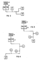
- the LMT's are assigned an arbitrary role code of 7 (111 binary). That portion of Figure 1 which comprises route 31 (11111) is shown in Figure 2.
- the outgoing communication signal produced by the ADS central station 12 shown in Figure 2 ' includes the route code 31 (11111) and the role code 7 (111).
- the role code identifies the first device in the identified route. In this example, the first device in route 31 (11111) is also the last device. Therefore, a communication signal including a role code of 7 (111) is intended for an end device.
- the route code 31 (11111) has no particular significance in this route since the first device is also the last device and is primarily response to the role code 7 (111).
- the LMT's 1, 2 and 3 are programmed with the role code 7 (111) so as to be capable of identifying communication signals intended for them. In a real power distribution network, hundreds of LMT's will be responsive to the role code (111). The LMT's are therefore additionally capable of being addressed individually or in groups as will be discussed hereinbelow.
- a signal path from the central station computer 14 to LMT 4 requires the use of a first repeater R1 and a second repeater R2.
- This signal path is assigned an arbitrary route code of 3 (00011) binary and is shown in Figure 3.
- the outgoing communication signal produced by the central station 12 must contain the route code 3 (00011) and a three digit role code which matches the out-detect bits of the first repeater R1.
- the first repeater R1 Upon receipt of the communication signal, the first repeater R1 will remove its out-detect bits from the communication signal and insert its in-detect bits which define a new role code.
- the in-detect bits inserted in the communication signal by the first repeater R1 must match the out-detect bits of the repeater R2 for the route 3 (00011). Since the next device in the route 3 (00011) after the second repeater R2 is an end device, the role code inserted in the communication signal by the second repeater R2 is 7 (111). The reader will recall that the role code 7 (111) was chosen, in conjunction with route 31 (11111), to represent an end device. For ease of manufacturing and programming, all end devices are therefore programmed to recognize the role code 7 (111).
- the repeaters R1 and R2 must each be down-loaded (which is discussed in detail hereinbelow) with a set of in-detect bits and out-detect bits for the route 3 (00011
- the in-detect bits and out-detect bits may be arbitrarily chosen so long as the in-detect bits of the first repeater R1 match the out-detect bits of the second repeater R2, and the final out-detect bits are 7 (111
- Table I indicates the information down- loaded into the repeaters R1 and R2.
- the signal produced by the central station computer 14 contains the following coded information,
- the signal retransmitted by repeater R1 contains the following coded information
- the signal retransmitted by repeater R2 contains the following coded information
- the role code varies as the communication signal is transmitted through the route, while the route code remains constant. Since one role code is used to designate the role of end devices, up to seven repeaters may be assigned to one route. Because all of the repeaters capable of being assigned to route 3 (00011) have not been used in route 3 (00011), the route 3 (00011) may be used to designate another route provided that different in-detect and out-detect bits are assigned to the individual repeaters. Each repeater may perform one role in as many routes as the repeater has available memory locations. This is illustrated by the following example.
- Figure 4 that portion of Figure 1 which comprises the signal path from the central station 12 to LMT 5 is shown.
- the repeaters R1 and R2 which are members of route 3 (00011), are also members of the route from the central station 12 to LMT 5.
- the assignment of an arbitrary route code, in-detect bits and out-detect bits results in the information illustrated in Table II being downloaded into repeaters R1, R2 and R3.
- the outgoing communication signal contains the following information:
- the outgoing communication signal contains the following information:
- communication between the central station computer 14 and any user location may be effected by identifying the repeaters, if any, necessary for retransmission of the communication signal, assigning those repeaters a route number, assigning each repeater a role within the route, and downloading the information to each repeater.
- the communication system disclosed herein provides great flexibility in allowing the communication system to be adapted to the existing structure and configuration of the power distribution network.
- Each repeater is preprogrammed with a unique address thereby allowing each repeater to be addressed as an end device.
- the repeater can be downloaded with the necessary route and role codes.
- the central station 12 produces an outgoing communication signal including any necessary route and role codes, the repeater's unique address and the new route codes, in-detect bits and out-detect bits.
- the new route to LMT 6 includes repeaters R1, R2, R3 and R6.
- Each of these repeaters will be individually addressed as an end device and will be down- loaded so as to recognize the new route code and the role which it is to perform as a member of this new route. This allows the communication system disclosed herein to perform its intended function in spite of the dynamic characteristics of the power distribution network thus providing a significant advantage not found in prior art systems.
- each repeater provides an added dimension to the present communication system in that the central station computer 14 can interrogate each repeater to ascertain the stored route codes, in-detect bits and out-detect bits. This information is coded in the response code of an incoming communication signal. With this information the signal paths from the central station 12 to various remote devices can be reconstructed. This ability to "feel" your way through the communication system is valuable in the event that data banks containing routing information are inadvertently lost or destroyed or if emergency rerouting is necessary before the required data banks can be called up and searched.
- Each repeater is also capable of being armed by outgoing communication signals so as to expect - the receipt of an incoming communication signal.
- the incoming communication signal may be produced by an LMT or a repeater in response to a received outgoing communication signal. Since the repeaters in the applicable route have been armed so as to expect an incoming communication signal, the incoming communication signal need only contain, in addition to the response code containing the desired information, the necessary role code. This reverse propagation is achieved by having each armed repeater temporarily reverse the in-detect and out-detect bits for the applicable route.
- the repeaters may also be armed by an outgoing communication signal so as to be prepared for the receipt and retransmission of supplemental outgoing communication signals.
- the communication signal In addition to the coded information carrying the desired message and the route and role codes, it is desirable for the communication signal to contain coded information so as to address individual LMT's or groups of LMT's.
- This coded information is in the form of a unique address which allows the central station 12 to communicate with an individual LMT or in the form of a block or universal address which allows the ADS central station 12 to communicate with groups of LMT's.
- Each LMT is preprogrammed with a unique address and at least one block address.
- each of the repeaters and LMT's is equipped with the necessary hardware needed to recognize the type of communication signal and to take appropriate action in response thereto.
- each repeater includes a receiver, logic control circuit, an amplifier and a transmitter.
- the logic control circuit performs the necessary comparisons, error checks and modifications of the communication signal as well as the arming of the repeater so as to waitfor additional communication signals, when appropriate.
- the logic control circuit also determines when the repeater is being addressed as an end device and manipulates the received data so as to store the downloaded information or direct the production of an incoming communication signal.
- Each LMT includes a receiver, logic control circuit and a transmitter.
- the LMT serves as an interface between the customer location and the power distribution system, and as such includes switches for load control functions and circuits for transferring data to and from the LMT and other devices at the customer location.
- the logic control circuit performs the necessary comparisons and error checks on the received communication signal.
- the logic control circuit is responsible for coordinating the response to the received signal. Responses may include receiving an outgoing communication signal including a message code from the central station, sending an incoming communication signal including a response code to the central station, sending or receiving data with other devices at the customer location, load shedding or the like.
Description
- This invention relates to network communication systems generally and, more specifically, to distribution network power line communication systems having bidirectionally addressable repeaters for providing bidirectional signal transmissions between a central station and remote devices.
- Considerable effort has been devoted in recent years to develop power distribution network carrier communication systems due to the increased desirability of performing certain automated functions, such as the automatic reading of utility meters, selective load control, performing load continuity checks, and the like. However, using the power distribution network as a communication link presents several unique problems not encountered in transmission through paths exclusively intended for communication signals nor in existing high voltage transmission line communication systems. The distribution line, along with the large number of distribution transformers attached thereto, is designed for the transmission of sixty hertz electrical power. The distribution line presents poor and erratically varying high frequency impedance characteristics which rapidly attenuate the communication signals. Additionally, the introduction of electrical noise and signal interference substantially reduced reliability.
- GB-A-1535834; and US-A-3,942,168; and US-A-3,911,415, all assigned to the assignee of the present invention, disclose some form of communication system via the distribution network of an electrical utility. US-A-3,911,415 discloses a power line communication system having signal reconditioning and frequency translating signal repeaters coupled to the conductors of a distribution network. Remote home terminals of different geographical zones are addressable at different frequencies to simplify address coding and isolation of potentially interfering carrier signals.
- GB-A-1535834 describes a power line communication system which transmits carrier communication signals through addressable repeaters defining communication zones including remote terminals in corresponding geographical zones or subregions. The uniquely addressed repeaters modify segments of the transmitted signal which represent their own address as repeated transmissions are propagated between a central control terminal and uniquely addressed remote terminals. Time delays in the repeater retransmissions avoid interfering signal reception and assure the maintenance of a single repeater in operation during each repeating cycle. Timed waiting is provided by the repeaters for response from the remote terminals. The remote terminal logic is activated without requiring the repeater code. The repeater receivers are always on except during retransmission.
- In the carrier communication system disclosed in US-A-3,942,168, signal repeaters are disposed in signal communication with distribution network power line conductors at each distribution transformer site. In this system, the repeater, in addition to amplifying a signal, provides a bypass circuit for the interrogation and response signals around the associated distribution transformers which present a significant attenuation at the frequencies of the communication signals, especially in the direction from the primary to the secondary winding. The repeaters also include means for delaying a received signal, with the delay time interval selected such that the amplified signal is not applied to the power line at the same time the repeater is to receive another signal. Each repeater includes two channels, each comprised of a receiver, logic and transmitter sections for handling the bidirectional flow of interrogation and response signals between the central communication terminal and the remote communication terminals at the customer sites.
- US-A-4,250,489 which is assigned to the same assignee as the present invention, discloses a power line carrier communication system having a branch or a pyramid configuration. Bidirectional addressable repeaters include an address recognition and a receive and transmit control logic circuits operated in a timed sequence of operations upon activation by an interrogation message transmitted from a central control terminal via one or more of the repeaters to a predetermined remote location. The branch organization of the repeaters includes groups of repeaters connected to the power line conductors of a distribution network so that each group defines a zone of repeaters. Each repeater zone is associated with remote terminals in geographical areas at progressively further distances from the central control terminal which defines the base or apex of the pyramiding branch configuration of the repeaters.
- A first, or zone A repeater group, forms the primary branch paths each extending to a separate group of intermediate branch paths including as many groups of second, or zone B repeaters, as there are primary branch paths. Further branch paths are formed including third, or zone C repeater groups, similarly extending from each of the separate intermediate branch paths. The latter branch paths are the furthest terminal branch paths in one preferred embodiment. Remote communication terminals are coupled in signal communication with the power line conductors for receiving and transmitting signals between an adjacent repeater in any of the zones depending on the correspondingly similar geographic locations of the remote terminals and repeaters with respect to the power lines.
- In this prior art communication system, an interrogation message originating at a central control terminal includes repeater address information having groups of repeater addresses in a predetermined segment of data bits in the message format. Each group is associated with a repeater zone and the binary coding of each group is associated with a separate repeater group. Thus, a reduced number of data bits is required and simplified address recognition logic is possible since large numbers of repeaters can have identical repeater addresses but are distinguishable because of their being in a different repeater address group and because of the different repeater address of the preceding repeater address group. False repeater activation is further prevented by each repeater's modification of its own repeater address segment of the retransmitted interrogation message to a predetermined null code such as all zero bits.
- Another reference disclosing a distribution system with a pyramid-type structure which relies on the selection of a particular terminal station for data collection purposes is found in US-A-3,944,723. A three-part code is transmitted from the central office in which each part of the code may be a combination of two frequencies out of a total of twelve frequencies for any paths selected. Still another reference which relies upon a fixed routing concept for a packet transmission system is described by G. L. Fultz and L. Kleinrock in "International Conference on Communications" from the Computer Science Department, U. of California in Los Angeles (Dept. of Defense DAHC-15-69-C-0285).
- A major disadvantage of the prior art power distribution communication systems is that the electric utilities' power distribution systems must be reconfigured so as to fit the required geometry of the communication system. In other words, communication zones, geographical zones, or the like, must be defined so that the electric utilities' power distribution systems will resemble the pyramid-like structure or the matrix-like structure required by the prior art communication systems. This is often a time consuming and expensive task given the fact that power distribution systems .have been expanding over several decades without any regard to the needs of a power distribution communication system.
- Another major disadvantage of the prior art power distribution communication systems stems from the fact that the distribution network is a very dynamic system, both physically as well as electrically. The system is physically dynamic due to accidents caused by bad weather, vandalism, etc, additions to the system, and other types of construction. The system is electrically dynamic since the utility has the capability, through the closing and opening of switch sets, to completely re-route the flow of electrical power. Thus, a power distribution system which has been reconfigured so as to fit the required geometry of a prior art communication system may require often and extensive revision so as to maintain the required geometry due to the dynamic nature of the system.
- The chief object of the present invention is to improve the communication system known from the prior art, especially US-A-3,944,723, so that reconfiguring of the electric utilities' power distribution system so as to fit the required geometry of the communication system (as mentioned before) is no longer necessary, thereby giving the communication system great flexibility and providing the user of the communication system considerable savings of time and man-power.
- The features of the characterizing part of
Claim 1 solve this object. The communication system according to this invention for an electric power distribution network, therefor, provides a significant improvement over the prior art, especially over pyramid-type communication systems which is primarily a result of the fact that the present system is not fixed in configuration as in the prior art, but instead is dynamically configurable to the existing power distribution network. This permits that an individual repeater may function as a member of a plurality of message routes under control of the central computer station such as when a section of the distribution network fails due to storm damage, and the messages can accordingly be rerouted to a specific end terminal location by changing the route and role codes of various repeaters to cause a message to propagate over a newly defined alternate route to the end terminal device. - The subclaims teach further embodiments of the invention, whereby especially
claim 2 is significant in that each repeater can be remotely reallocated to perform a variety of functions within the communication system in order to dynamically reconfigure it for outages in the system. - The invention will become more readily apparent from the following exemplary description, taken in connection with the accompanying drawings, in which:
- Figure 1 illustrates a distribution network communication system constructed according to the teachings of the present invention and implemented on a power distribution network;
- Figure 2 illustrates that portion of Figure 1 which comprises the signal path from the automated distribution system central station to the load management terminals within the second substation's communication range;
- Figure 3 illustrates that portion of Figure 1 which comprises the signal path from the automated distribution system central station to load
management terminal number 4; and - Figure 4 illustrates that portion of Figure 1 which comprises the signal path from the automatic distribution system central station to load
management terminal number 5. - The present disclosure reveals a communication system used in conjunction with a power distribution network used by a utility to deliver electrical power to its customers, although the concepts disclosed need not be limited to this type of distribution network. Each customer location is equipped with a remote terminal which contains a role code identifying the remote terminal as an end device as well as a plurality of address codes. A central station produces an outgoing communication signal. A communication link couples the central station to the power distribution network. A plurality of signal repeaters are used, where needed, to receive, amplify and retransmit the outgoing communication signal. The signal repeaters also contaon a preprogrammed, unique address code which allows each repeater to be addressed as an end device. The outgoing communication signal produced by the central station is intended for at least one end device, be it a signal repeater or a remote terminal.
- The outgoing communication signal includes a route code identifying a signal path from the central station to the end device the user wishes to communicate with, a role code identifying the first device in the identified route, an address code and a message code. Each of the signal repeaters contains a plurality of stored route codes and role codes which are remotely modifiable. Upon receipt of an outgoing communication signal by a signal repeater, which is not the intended end device, the repeater compares the received route and role codes to the- stored route and role codes. If there is a match, the signal repeater removes its role code from the outgoing communication signal and inserts the role code of the next device in the identified route. The modified outgoing communication signal is retransmitted and the signal repeater is prepared, when appropriate, to receive an incoming signal. The modified outgoing communication signal is similarly modified and retransmitted by the other signal repeaters (if any) in the identified route until the message code is received by the end device.
- Each remote terminal includes means responsive to the message code for performing various functions such as load shedding, time ' keeping, meter reading, etc., when the remote terminal is the intended end device. When appropriate, the remote terminal produces an incoming communication signal intended for the central control station. The incoming communication signal includes a role code identifying the next device in the identified route and a response code containing the desired information. No route code is necessary since the signal repeaters in the identified route have been prepared by the outgoing communication signal.
- When addressed as an end device, each signal repeater is downloaded with route and role codes by an outgoing communication signal. Downloading is the process by which the remotely modifiable route and role codes stored within the signal repeater are modified so as to allow the repeater to perform a new role in an established route or to perform a new role in a new route. The ability to download the signal repeaters allows the communication system to be easily adapted to the existing distribution network and is considered to be an important feature of the present invention.
- In Figure 1 a
communication system 10 constructed according to the teachings of the present invention is shown. Thecommunication system 10 is intended to be used in conjunction with a utility's power distribution network, although the concepts need not be limited thereto. An automated distribution systemcentral station 12 is the first device in thecommunication system 10. Thecentral station 12 contains acentral station computer 14 which provides a central control point for both data collection and maintenance of the information required to control thecommunication system 10. Communication signals generated by thecentral station computer 14 are considered to be outgoing while communication signals received by the central station computer are considered to be incoming. Thecentral station computer 14 is responsible for generating the outgoing communication signals which contain coded information necessary for the proper operation of thecommunication system 10. The communication signals produced by thecentral station computer 14 are delivered to a first substation (not shown), or other signal injection point, through afirst modem 16 and a first dedicated phone line 17. Similarly, the communication signals are delivered to asecond substation 21 through asecond modem 19 and a seconddedicated phone line 20 and to an Nth substation (not shown), or other signal injection point, through anNth modem 23 and an Nthdedicated phone line 24. - The communication equipment located at the
second substation 21 is representative of the equipment located at the other signal injection points. The communication equipment located at thesecond substation 21 includes acarrier control unit 26, a signal coupling unit 28, and acapacitor 30. The carrier control unit acts primarily as a protocol translator, accepting information in a serial character mode from thephone line 20 and translating it into the larger serial word structures that are used on the power line carrier. In the reverse mode, it takes the - incoming information returned by the power line carrier and places it back on thephone line 20, with a modified protocol, for return to thecentral station 12. The signal coupling unit 28 and thecapacitor 30 comprise a primary coupling assembly for coupling thecarrier control unit 26 to aprimary distribution feeder 32. In one embodiment, eachcarrier control unit 26 may be coupled to up to eight primary distribution feeders through eight individual primary coupling assemblies. Thesecond modem 19, the seconddedicated phone line 20, and the communication equipment located at thesecond substation 21 provide a communication link for coupling thecentral station computer 14 to theprimary distribution feed 32. - A
capacitor bank 33 and acapacitor blocking unit 34 are connected between theprimary distribution feeder 32 and ground. Thecapacitor blocking unit 34 serves as a high impedance for the energy of the carrier communication signal thereby preventing the carrier communication energy from being shorted to ground. The remainder of figure 1 illustrates the electric utility's power distribution network shown generally byreference numeral 36. Thepower distribution network 36 is comprised of theprimary distribution feed 32, a plurality of secondary distribution feeders, a plurality of signal repeaters and a plurality of customer locations represented by load management terminals (LMT). The reader should recognize that thepower distribution network 36 shown in Figure 1 is greatly simplified and in reality the customer locations serviced by each repeater will number in the hundreds. Also, customer locations may contain any type of remote equipment and need not be limited to LMT's. - In order for the
central station computer 14 to communicate with individual LMT's, it is necessary to define a route from thecentral station computer 14 to the desired LMT. If the LMT is not located within the communication range of the carrier control unit, one or more repeaters must be included in the route. When one or more repeaters are included in the route it is necessary to inform each repeater of the role it is to perform within the predetermined route. Accordingly, the communication signal produced by thecentral station computer 14 must contain route and role information and each repeater must be capable of recognizing its role within each route in which it participates. - In one embodiment, the outgoing communication signal contains, in addition to other information, a five bit route code and a three bit role code. The five bit route code contained within the communication signal is fixed and does not vary as the communication signal propagates through the
power distribution network 36. However, the role code does change as the communication signal propagates through thepower distribution network 36 since each device in the route must perform a unique role within that route. A five bit route code allows for the assignment of 32 unique route codes. A three bit role code allows for eight unique role codes. With eight available roles within each route, a route may contain up to seven repeaters and at least one end device. - The actual assignment of route and role codes is totally arbitrary and provides for maximum flexibility when configuring the
communication system 10 to the existing configuration of thepower distribution network 36. Even though the assignment of route codes and role codes is arbitrary, certain rules must be followed. When a route is established from thecentral station computer 14 to an LMT, each repeater within that route must be assigned the same route code. Each repeater contains a plurality of stored route codes, which are remotely modifiable, and may participate in as many routes as can be stored in available memory locations. For each route code stored by a repeater a set of remotely modifiable in-detect bits and out-detect bits is also stored. The in-detect bits and out-detect bits are used by the repeater to determine its role within each route of which it is a member. - When a repeater receives an outgoing communication signal, it compares the remotely modifiable route codes and associated out-detect bits to the received route code and role code, respectively. When a match is found the repeater removes its out-detect bits, or role code, from the received communication signal and substitutes its in-detect bits, or new role code. Therefore, for the repeaters within a given route to operate sequentially, the out-detect bits of the first repeater must match the received role code of the outgoing communication signal. The in-detect bits inserted into the outgoing communication signal by the first repeater must match the out detect bits of the second repeater in the route. Similarly, the in-detect bits inserted by the second repeater into the modified outgoing communication signal must match the out-detect bits of the third repeater within the route. In this .manner, information propagates through a predetermined route.
- In summary, the two basic rules for assigning route and role codes are that each device within a route must have the same route number, and the in-detect bits of one device must match the out-detect bits of the device following it within the given route. Several examples using these rules will aid in the understanding of the present invention and will illustrate the ease with which the
communication system 10 can be configured to the existing structure of thepower distribution network 36. - In Figure 1, load
management terminals number central station computer 14 to the LMT's is assigned an arbitrary route code of 31 (11111 binary). The LMT's are assigned an arbitrary role code of 7 (111 binary). That portion of Figure 1 which comprises route 31 (11111) is shown in Figure 2. The outgoing communication signal produced by the ADScentral station 12 shown in Figure 2'includes the route code 31 (11111) and the role code 7 (111). The role code identifies the first device in the identified route. In this example, the first device in route 31 (11111) is also the last device. Therefore, a communication signal including a role code of 7 (111) is intended for an end device. The route code 31 (11111) has no particular significance in this route since the first device is also the last device and is primarily response to the role code 7 (111 The LMT's 1, 2 and 3 are programmed with the role code 7 (111) so as to be capable of identifying communication signals intended for them. In a real power distribution network, hundreds of LMT's will be responsive to the role code (111). The LMT's are therefore additionally capable of being addressed individually or in groups as will be discussed hereinbelow. - Returning to Figure 1, a signal path from the
central station computer 14 toLMT 4 requires the use of a first repeater R1 and a second repeater R2. This signal path is assigned an arbitrary route code of 3 (00011) binary and is shown in Figure 3. The outgoing communication signal produced by thecentral station 12 must contain the route code 3 (00011) and a three digit role code which matches the out-detect bits of the first repeater R1. Upon receipt of the communication signal, the first repeater R1 will remove its out-detect bits from the communication signal and insert its in-detect bits which define a new role code. For the second repeater R2 to perform its proper role in the route 3 (00011), the in-detect bits inserted in the communication signal by the first repeater R1 must match the out-detect bits of the repeater R2 for the route 3 (00011). Since the next device in the route 3 (00011) after the second repeater R2 is an end device, the role code inserted in the communication signal by the second repeater R2 is 7 (111). The reader will recall that the role code 7 (111) was chosen, in conjunction with route 31 (11111), to represent an end device. For ease of manufacturing and programming, all end devices are therefore programmed to recognize the role code 7 (111). Finally, for the communication signal produced by thecentral station 12 to be properly relayed to theLMT 4, the repeaters R1 and R2 must each be down-loaded (which is discussed in detail hereinbelow) with a set of in-detect bits and out-detect bits for the route 3 (00011 The in-detect bits and out-detect bits may be arbitrarily chosen so long as the in-detect bits of the first repeater R1 match the out-detect bits of the second repeater R2, and the final out-detect bits are 7 (111 - Table I, below, indicates the information down- loaded into the repeaters R1 and R2.

- The signal produced by the
central station computer 14 contains the following coded information, - where the first three bits 010 identify repeater R1's role and the remaining five bits 00011
identify route 3. The signal retransmitted by repeater R1 contains the following coded information, - where the first three bits 001 identify repeater R2's role and the remaining five bits 00011
identify route 3. The signal retransmitted by repeater R2 contains the following coded information, - where the first three bits 111 identify the last, or end device, and the remaining five bits 00011
identify route 3. - As can be seen from the above discussion, the role code varies as the communication signal is transmitted through the route, while the route code remains constant. Since one role code is used to designate the role of end devices, up to seven repeaters may be assigned to one route. Because all of the repeaters capable of being assigned to route 3 (00011) have not been used in route 3 (00011), the route 3 (00011) may be used to designate another route provided that different in-detect and out-detect bits are assigned to the individual repeaters. Each repeater may perform one role in as many routes as the repeater has available memory locations. This is illustrated by the following example.
- Turning to Figure 4, that portion of Figure 1 which comprises the signal path from the
central station 12 toLMT 5 is shown. As can be seen in Figure 4, the repeaters R1 and R2, which are members of route 3 (00011), are also members of the route from thecentral station 12 toLMT 5. The assignment of an arbitrary route code, in-detect bits and out-detect bits results in the information illustrated in Table II being downloaded into repeaters R1, R2 and R3.
- The outgoing communication signal contains the following information:
- 01101000 when transmitted by the
central station 12, - 01001000 when transmitted by repeater R1,
- 10101000 when transmitted by repeater R2, and
- 11101000 when transmitted by repeater R3.
- Returning to Figure 1, a similar analysis can be made to create a route from the
central station 12 toLMT 6. Table III summarizes the information downloaded into repeaters R4 and R5.
- The outgoing communication signal contains the following information:
- 01110001 when transmitted by the
central station 12, - 01010001 when transmitted by repeater R4, and
- 11110001 when transmitted by
repeater 5. - In summary, communication between the
central station computer 14 and any user location may be effected by identifying the repeaters, if any, necessary for retransmission of the communication signal, assigning those repeaters a route number, assigning each repeater a role within the route, and downloading the information to each repeater. The communication system disclosed herein provides great flexibility in allowing the communication system to be adapted to the existing structure and configuration of the power distribution network. - Each repeater is preprogrammed with a unique address thereby allowing each repeater to be addressed as an end device. When addressed as an end device the repeater can be downloaded with the necessary route and role codes. In order to download a repeater the
central station 12 produces an outgoing communication signal including any necessary route and role codes, the repeater's unique address and the new route codes, in-detect bits and out-detect bits. For example, in Figure 1, should one of the repeaters R4 or R5 malfunction, or if the power distribution network develops a fault along route 17 (10001), an new route toLMT 6 can be created. The new route toLMT 6 includes repeaters R1, R2, R3 and R6. Each of these repeaters will be individually addressed as an end device and will be down- loaded so as to recognize the new route code and the role which it is to perform as a member of this new route. This allows the communication system disclosed herein to perform its intended function in spite of the dynamic characteristics of the power distribution network thus providing a significant advantage not found in prior art systems. - The ability of each repeater to be uniquely addressed as an end device provides an added dimension to the present communication system in that the
central station computer 14 can interrogate each repeater to ascertain the stored route codes, in-detect bits and out-detect bits. This information is coded in the response code of an incoming communication signal. With this information the signal paths from thecentral station 12 to various remote devices can be reconstructed. This ability to "feel" your way through the communication system is valuable in the event that data banks containing routing information are inadvertently lost or destroyed or if emergency rerouting is necessary before the required data banks can be called up and searched. - Each repeater is also capable of being armed by outgoing communication signals so as to expect - the receipt of an incoming communication signal. The incoming communication signal may be produced by an LMT or a repeater in response to a received outgoing communication signal. Since the repeaters in the applicable route have been armed so as to expect an incoming communication signal, the incoming communication signal need only contain, in addition to the response code containing the desired information, the necessary role code. This reverse propagation is achieved by having each armed repeater temporarily reverse the in-detect and out-detect bits for the applicable route. The repeaters may also be armed by an outgoing communication signal so as to be prepared for the receipt and retransmission of supplemental outgoing communication signals.
- In addition to the coded information carrying the desired message and the route and role codes, it is desirable for the communication signal to contain coded information so as to address individual LMT's or groups of LMT's. This coded information is in the form of a unique address which allows the
central station 12 to communicate with an individual LMT or in the form of a block or universal address which allows the ADScentral station 12 to communicate with groups of LMT's. Each LMT is preprogrammed with a unique address and at least one block address. - Each of the repeaters and LMT's is equipped with the necessary hardware needed to recognize the type of communication signal and to take appropriate action in response thereto. Specifically, each repeater includes a receiver, logic control circuit, an amplifier and a transmitter. The logic control circuit performs the necessary comparisons, error checks and modifications of the communication signal as well as the arming of the repeater so as to waitfor additional communication signals, when appropriate. The logic control circuit also determines when the repeater is being addressed as an end device and manipulates the received data so as to store the downloaded information or direct the production of an incoming communication signal.
- Each LMT includes a receiver, logic control circuit and a transmitter. The LMT serves as an interface between the customer location and the power distribution system, and as such includes switches for load control functions and circuits for transferring data to and from the LMT and other devices at the customer location. The logic control circuit performs the necessary comparisons and error checks on the received communication signal. The logic control circuit is responsible for coordinating the response to the received signal. Responses may include receiving an outgoing communication signal including a message code from the central station, sending an incoming communication signal including a response code to the central station, sending or receiving data with other devices at the customer location, load shedding or the like.
- The foregoing discussion of the present communication system is made in conjunction with an electric utility's power distribution network. This particular application is intended as an illustration and not a limitation. Those skilled in the art will recognize the flexibility of the communication system disclosed herein and its adaptability to other distribution networks such as a cable television system.
Claims (9)
Applications Claiming Priority (2)
| Application Number | Priority Date | Filing Date | Title |
|---|---|---|---|
| US252682 | 1981-04-09 | ||
| US06/252,682 US4427968A (en) | 1981-04-09 | 1981-04-09 | Distribution network communication system with flexible message routes |
Publications (2)
| Publication Number | Publication Date |
|---|---|
| EP0062870A1 EP0062870A1 (en) | 1982-10-20 |
| EP0062870B1 true EP0062870B1 (en) | 1986-07-23 |
Family
ID=22957062
Family Applications (1)
| Application Number | Title | Priority Date | Filing Date |
|---|---|---|---|
| EP82102878A Expired EP0062870B1 (en) | 1981-04-09 | 1982-04-03 | Distribution network communication system |
Country Status (10)
| Country | Link |
|---|---|
| US (1) | US4427968A (en) |
| EP (1) | EP0062870B1 (en) |
| JP (1) | JPS57178437A (en) |
| KR (1) | KR880002161B1 (en) |
| AU (1) | AU554755B2 (en) |
| BR (1) | BR8202001A (en) |
| CA (1) | CA1177929A (en) |
| DE (1) | DE3272086D1 (en) |
| FI (1) | FI821238L (en) |
| ZA (1) | ZA822315B (en) |
Families Citing this family (67)
| Publication number | Priority date | Publication date | Assignee | Title |
|---|---|---|---|---|
| CA1194957A (en) * | 1981-09-14 | 1985-10-08 | Hitoshi Fukagawa | Data transmission system utilizing power line |
| US4965825A (en) | 1981-11-03 | 1990-10-23 | The Personalized Mass Media Corporation | Signal processing apparatus and methods |
| USRE47642E1 (en) | 1981-11-03 | 2019-10-08 | Personalized Media Communications LLC | Signal processing apparatus and methods |
| US7831204B1 (en) | 1981-11-03 | 2010-11-09 | Personalized Media Communications, Llc | Signal processing apparatus and methods |
| EP0091142A3 (en) * | 1982-04-07 | 1984-03-28 | Motorola Israel Limited | Signal processing unit |
| US4675668A (en) * | 1982-12-30 | 1987-06-23 | Sharp Kabushiki Kaisha | Data transmission system over building wiring |
| US4589075A (en) * | 1983-02-23 | 1986-05-13 | Buennagel James A | Remote load data acquisition and control system for a power network |
| JPS60103832A (en) * | 1983-11-11 | 1985-06-08 | Fujitsu Ltd | Radio relay system |
| US4668934A (en) * | 1984-10-22 | 1987-05-26 | Westinghouse Electric Corp. | Receiver apparatus for three-phase power line carrier communications |
| EP0200842B1 (en) * | 1985-04-30 | 1992-10-14 | International Business Machines Corporation | Modem controlling a modem network |
| GB8511758D0 (en) * | 1985-05-09 | 1985-06-19 | Emi Ltd | Data communications systems |
| US4656593A (en) * | 1985-05-20 | 1987-04-07 | Westinghouse Electric Corp. | Multi-function load controller for carrier load control subsystem |
| US4692761A (en) * | 1985-06-21 | 1987-09-08 | Robinton Products, Inc. | Adaptive communication network and method |
| US4638298A (en) * | 1985-07-16 | 1987-01-20 | Telautograph Corporation | Communication system having message repeating terminals |
| JPS6258744A (en) * | 1985-09-09 | 1987-03-14 | Fujitsu Ltd | Polling system |
| US4766414A (en) * | 1986-06-17 | 1988-08-23 | Westinghouse Electric Corp. | Power line communication interference preventing circuit |
| US4912461A (en) * | 1986-11-05 | 1990-03-27 | Cellular Control Systems Corporation | Apparatus and network for transferring packets of electronic signals and associated method |
| JPH0634537B2 (en) * | 1987-01-12 | 1994-05-02 | 富士通株式会社 | Inter-device communication control method |
| JPH073979B2 (en) * | 1987-09-14 | 1995-01-18 | 三菱電機株式会社 | Distant supervisory control system |
| AU621581B2 (en) * | 1987-11-10 | 1992-03-19 | Echelon Corporation | Protocol for network having a plurality of intelligent cells |
| JPH03505642A (en) * | 1987-11-10 | 1991-12-05 | エシャロン・コーポレーション | Device and method for detecting and controlling via network |
| US4969146A (en) * | 1987-11-10 | 1990-11-06 | Echelon Systems Corporation | Protocol for network having a plurality of intelligent cells |
| KR920009402B1 (en) * | 1987-12-15 | 1992-10-16 | 미쓰비시덴기 가부시끼가이샤 | Communication device |
| WO1989012345A1 (en) * | 1988-06-08 | 1989-12-14 | The South East Queensland Electricity Board | Controller and a network controller system |
| AU615556B2 (en) * | 1988-06-08 | 1991-10-03 | South East Queensland Electricity Corporation | Controller and a network controller system |
| JP2865682B2 (en) * | 1988-12-23 | 1999-03-08 | 株式会社日立製作所 | Information processing system and information processing method |
| FR2645674B1 (en) * | 1989-04-07 | 1993-10-01 | Sncf | INSTALLATION OF REMOTE CONTROL AND REMOTE CONTROL OF THE OPENING OR CLOSING STATE OF A CONTACT AMONG A PLURALITY OF CONTACTS |
| US5032833A (en) * | 1989-04-27 | 1991-07-16 | Schlumberger Industries, Inc. | Adaptive network routing for power line communications |
| US4977353A (en) * | 1989-08-31 | 1990-12-11 | Minitronics Pty Limited | Communication system for single point emergency lighting |
| US5553094A (en) | 1990-02-15 | 1996-09-03 | Iris Systems, Inc. | Radio communication network for remote data generating stations |
| EP0445448B1 (en) * | 1990-03-06 | 1995-05-17 | Mitsubishi Denki Kabushiki Kaisha | Control and supervisory system for power distribution equipment |
| US5225994A (en) * | 1990-03-06 | 1993-07-06 | Mitsubishi Denki Kabushiki Kaisha | Control and supervisory system for power distribution equipment |
| FR2677190B1 (en) * | 1991-06-03 | 1993-09-03 | Merlin Gerin | TELETRANSMISSION DEVICE WITH IN LINE CARRIERS FOR CONTROLLED CONTROL OF AN ELECTRICAL NETWORK, PARTICULARLY AT MEDIUM VOLTAGE. |
| CA2076171C (en) * | 1991-09-26 | 1998-08-18 | Brooks W. Taylor | Computer controlled lighting system with intelligent data distribution networks |
| DE4207784C2 (en) * | 1992-03-11 | 1993-12-23 | Martin Nimbach | Freely programmable installation network |
| IT1257167B (en) * | 1992-10-27 | 1996-01-05 | METHOD FOR IMPROVING THE MANAGEMENT OF DISTRIBUTION NETWORKS, IN PARTICULAR OF GAS, WATER, ELECTRICITY, HEAT. | |
| US5406249A (en) * | 1993-03-09 | 1995-04-11 | Metricom, Inc. | Method and structure for coupling power-line carrier current signals using common-mode coupling |
| DE4400765C2 (en) * | 1994-01-13 | 2002-11-14 | Cm Elektronik Gmbh | Device for data transmission over the power supply network |
| US5835005A (en) * | 1994-07-13 | 1998-11-10 | Omron Corporation | Power-line data transmission method and system utilizing relay stations |
| GB9416688D0 (en) * | 1994-08-18 | 1994-10-12 | Remote Metering Systems Ltd | Mains signalling systems |
| US5818821A (en) * | 1994-12-30 | 1998-10-06 | Intelogis, Inc. | Universal lan power line carrier repeater system and method |
| JP3349861B2 (en) * | 1995-03-17 | 2002-11-25 | 富士通株式会社 | Wireless LAN system |
| FR2734118B1 (en) * | 1995-05-12 | 1997-07-11 | Duranton Rene | DEVICE FOR REMOTE CONTROL AND MONITORING OF A DISCHARGE LAMP |
| US5848054A (en) * | 1996-02-07 | 1998-12-08 | Lutron Electronics Co. Inc. | Repeater for transmission system for controlling and determining the status of electrical devices from remote locations |
| US5978371A (en) * | 1997-03-31 | 1999-11-02 | Abb Power T&D Company Inc. | Communications module base repeater |
| US5986574A (en) | 1997-10-16 | 1999-11-16 | Peco Energy Company | System and method for communication between remote locations |
| US20020120569A1 (en) * | 1997-10-16 | 2002-08-29 | Day Mark E. | System and method for communication between remote locations |
| WO1999045510A2 (en) | 1998-03-03 | 1999-09-10 | Itron, Inc. | Method and system for reading intelligent utility meters |
| US6480510B1 (en) | 1998-07-28 | 2002-11-12 | Serconet Ltd. | Local area network of serial intelligent cells |
| US6320501B1 (en) | 1999-05-25 | 2001-11-20 | Pittway Corporation | Multiple sensor system for alarm determination with device-to-device communications |
| WO2001078307A2 (en) | 2000-04-10 | 2001-10-18 | Zensys A/S | Rf home automation system comprising nodes with dual functionality |
| US6842459B1 (en) | 2000-04-19 | 2005-01-11 | Serconet Ltd. | Network combining wired and non-wired segments |
| FR2808149B1 (en) * | 2000-04-19 | 2003-01-31 | Electricite De France | METHOD AND DEVICE FOR ENABLING CONTROL OF AN ELECTRIC APPARATUS CONNECTED TO A NETWORK |
| US6879806B2 (en) | 2001-06-01 | 2005-04-12 | Zensys A/S | System and a method for building routing tables and for routing signals in an automation system |
| DE10128258A1 (en) * | 2001-06-12 | 2002-12-19 | Luxmate Controls Gmbh Dornbirn | Power line control system for street lights repeats signals if preset transmit receive cycle |
| US6995685B2 (en) * | 2001-09-25 | 2006-02-07 | Landis+Gyr, Inc. | Utility meter power arrangements and methods |
| ITMI20012726A1 (en) * | 2001-12-20 | 2003-06-20 | Enel Distribuzione Spa | SYSTEM OF REMOTE CONSUMPTION OF CONSUMPTION AND REMOTE MANAGEMENT OF USERS ALSO DISTRIBUTED OF A DOMESTIC TYPE |
| JP2003244039A (en) * | 2002-02-20 | 2003-08-29 | Alps Electric Co Ltd | Switchboard and wired communication network system using the switchboard |
| US20050090936A1 (en) * | 2003-10-24 | 2005-04-28 | Hitt Dale K. | Two-wire control of sprinkler system |
| IL154921A (en) * | 2003-03-13 | 2011-02-28 | Mosaid Technologies Inc | Telephone system having multiple distinct sources and accessories therefor |
| GB2407898B (en) * | 2003-11-04 | 2007-09-19 | Bombardier Transp Gmbh | Distribution of network configuration specific commands |
| US8984500B2 (en) * | 2004-06-14 | 2015-03-17 | Hewlett-Packard Development Company, L.P. | Programming a computing node connected to a sensor and an actuator |
| US20060079230A1 (en) * | 2004-10-13 | 2006-04-13 | Russell Thomas C | System and methods for redundant networks |
| NZ563876A (en) | 2006-07-26 | 2009-06-26 | Thomas & Betts Int | Emergency lighting system |
| US20090302870A1 (en) * | 2006-09-12 | 2009-12-10 | Paterson Neil D | Soil moisture sensor with data transmitter |
| WO2011063847A1 (en) * | 2009-11-27 | 2011-06-03 | Telefonaktiebolaget Lm Ericsson (Publ) | Transferring messages in a communications network |
| CN102710030B (en) * | 2012-07-04 | 2016-03-16 | 江苏省电力公司扬州供电公司 | A kind of residential area power distribution room integral intelligent supervising device |
Family Cites Families (16)
| Publication number | Priority date | Publication date | Assignee | Title |
|---|---|---|---|---|
| US3484694A (en) | 1966-03-16 | 1969-12-16 | Sangamo Electric Co | Data transmission system wherein system control is divided between a plurality of levels for remote location activation |
| US3693155A (en) | 1971-03-23 | 1972-09-19 | Nat Telecommunications System | Communication system |
| GB1436117A (en) | 1972-05-04 | 1976-05-19 | Kent Meters Ltd | Interrogation of remote stations |
| US3854122A (en) | 1972-12-12 | 1974-12-10 | Robertshaw Controls Co | Remote station addressing system |
| US3846703A (en) | 1973-02-28 | 1974-11-05 | Tocom | Noise control system for transmission network |
| US3925763A (en) | 1973-09-13 | 1975-12-09 | Romesh Tekchand Wadhwani | Security system |
| US3911415A (en) | 1973-12-18 | 1975-10-07 | Westinghouse Electric Corp | Distribution network power line carrier communication system |
| US3973240A (en) | 1974-12-05 | 1976-08-03 | General Electric Company | Power line access data system |
| US3944723A (en) * | 1974-12-05 | 1976-03-16 | General Electric Company | Station for power line access data system |
| US3967264A (en) | 1975-01-31 | 1976-06-29 | Westinghouse Electric Corporation | Distribution network power line communication system including addressable interrogation and response repeater |
| US3942168A (en) | 1975-01-31 | 1976-03-02 | Westinghouse Electric Corporation | Distribution network power line communication system |
| JPS52127005A (en) | 1976-04-16 | 1977-10-25 | Pioneer Electronic Corp | Bidirectional data communication system |
| US4210901A (en) | 1977-04-25 | 1980-07-01 | Westinghouse Electric Corp. | Signal repeater for a distribution network communication system |
| US4130874A (en) | 1977-06-13 | 1978-12-19 | Westinghouse Electric Corp. | Load management terminal having plural selectable address formats for a power line communication system |
| US4250489A (en) | 1978-10-31 | 1981-02-10 | Westinghouse Electric Corp. | Distribution network communication system having branch connected repeaters |
| US4228422A (en) | 1978-11-30 | 1980-10-14 | The United States Of America As Represented By The Administrator Of The National Aeronautics And Space Administration | System for displaying at a remote station data generated at a central station and for powering the remote station from the central station |
-
1981
- 1981-04-09 US US06/252,682 patent/US4427968A/en not_active Expired - Lifetime
-
1982
- 1982-03-31 AU AU82203/82A patent/AU554755B2/en not_active Ceased
- 1982-03-31 CA CA000400051A patent/CA1177929A/en not_active Expired
- 1982-04-02 ZA ZA822315A patent/ZA822315B/en unknown
- 1982-04-03 DE DE8282102878T patent/DE3272086D1/en not_active Expired
- 1982-04-03 EP EP82102878A patent/EP0062870B1/en not_active Expired
- 1982-04-07 FI FI821238A patent/FI821238L/en not_active Application Discontinuation
- 1982-04-07 BR BR8202001A patent/BR8202001A/en not_active IP Right Cessation
- 1982-04-08 JP JP57057450A patent/JPS57178437A/en active Pending
- 1982-04-09 KR KR8201569A patent/KR880002161B1/en active
Non-Patent Citations (1)
| Title |
|---|
| INTERNATIONAL CONFERENCE ON COMMUNICATIONS, June 14,15,16, 1971, Institute of electrical and electronics engineers, Inc., Montreal (CA) G.L. FULTZ et al.: "Adaptive routing techniques for store-and-forward computer-communication networks", pages 39.1 - 39.8 * |
Also Published As
| Publication number | Publication date |
|---|---|
| FI821238L (en) | 1982-10-10 |
| FI821238A0 (en) | 1982-04-07 |
| CA1177929A (en) | 1984-11-13 |
| US4427968A (en) | 1984-01-24 |
| DE3272086D1 (en) | 1986-08-28 |
| AU554755B2 (en) | 1986-09-04 |
| ZA822315B (en) | 1983-05-25 |
| AU8220382A (en) | 1983-10-13 |
| BR8202001A (en) | 1983-03-15 |
| KR880002161B1 (en) | 1988-10-17 |
| JPS57178437A (en) | 1982-11-02 |
| EP0062870A1 (en) | 1982-10-20 |
Similar Documents
| Publication | Publication Date | Title |
|---|---|---|
| EP0062870B1 (en) | Distribution network communication system | |
| US4210901A (en) | Signal repeater for a distribution network communication system | |
| AU600577B2 (en) | Lan communication system and medium adapter for use therewith | |
| US4953194A (en) | Automated documentation system for a communications network | |
| US4638298A (en) | Communication system having message repeating terminals | |
| US4250489A (en) | Distribution network communication system having branch connected repeaters | |
| US5554968A (en) | Data communication using power lines | |
| US5060226A (en) | Telecommunications network test system | |
| EP0157704A2 (en) | Duplex transmission mechanism for digital telephones | |
| TW357511B (en) | Method and system for providing low-cost high-speed data services | |
| EP0201253A2 (en) | Power line communications system | |
| US3204033A (en) | Interconnecting network for a telecommunication system | |
| EP0203150B1 (en) | Method and apparatus for looping around a digital transmission line at a channel unit | |
| EP0203151B1 (en) | Loop around data channel unit | |
| US4538033A (en) | Data bridge with gating and/or testing | |
| US4583215A (en) | Telephone line access system for main distribution frame | |
| Inose | Communication networks | |
| Kirkham et al. | Design considerations for a fiber optic communications network for power systems | |
| EP0501446B1 (en) | Multiple access communication system capable of deciding a connection route among a central station, repeater stations, and terminal stations | |
| US6836508B1 (en) | Method and apparatus for using unintended radio frequency propagation in a network | |
| EP0365649A4 (en) | Apparatus and method for mapping the connectivity of communications systems with multiple communications paths | |
| IE70232B1 (en) | A voice and data network | |
| RU2027307C1 (en) | System for transmitting additional information along wire broadcasting line | |
| Gower et al. | Packet Radio Integrated System Module (PRISM)-Design Document | |
| EP0157536A2 (en) | Telephone line access system for main distribution frame |
Legal Events
| Date | Code | Title | Description |
|---|---|---|---|
| PUAI | Public reference made under article 153(3) epc to a published international application that has entered the european phase |
Free format text: ORIGINAL CODE: 0009012 |
|
| AK | Designated contracting states |
Designated state(s): CH DE FR GB IT |
|
| 17P | Request for examination filed |
Effective date: 19830413 |
|
| ITF | It: translation for a ep patent filed |
Owner name: ING. ZINI MARANESI & C. S.R.L. |
|
| GRAA | (expected) grant |
Free format text: ORIGINAL CODE: 0009210 |
|
| AK | Designated contracting states |
Kind code of ref document: B1 Designated state(s): CH DE FR GB IT LI |
|
| REF | Corresponds to: |
Ref document number: 3272086 Country of ref document: DE Date of ref document: 19860828 |
|
| ET | Fr: translation filed | ||
| PLBE | No opposition filed within time limit |
Free format text: ORIGINAL CODE: 0009261 |
|
| STAA | Information on the status of an ep patent application or granted ep patent |
Free format text: STATUS: NO OPPOSITION FILED WITHIN TIME LIMIT |
|
| 26N | No opposition filed | ||
| PG25 | Lapsed in a contracting state [announced via postgrant information from national office to epo] |
Ref country code: LI Effective date: 19880430 Ref country code: CH Effective date: 19880430 |
|
| REG | Reference to a national code |
Ref country code: CH Ref legal event code: PL |
|
| ITTA | It: last paid annual fee | ||
| PGFP | Annual fee paid to national office [announced via postgrant information from national office to epo] |
Ref country code: FR Payment date: 19990322 Year of fee payment: 18 |
|
| PG25 | Lapsed in a contracting state [announced via postgrant information from national office to epo] |
Ref country code: FR Free format text: LAPSE BECAUSE OF NON-PAYMENT OF DUE FEES Effective date: 20001229 |
|
| REG | Reference to a national code |
Ref country code: FR Ref legal event code: ST |
|
| PGFP | Annual fee paid to national office [announced via postgrant information from national office to epo] |
Ref country code: GB Payment date: 20010316 Year of fee payment: 20 |
|
| PGFP | Annual fee paid to national office [announced via postgrant information from national office to epo] |
Ref country code: DE Payment date: 20010421 Year of fee payment: 20 |
|
| REG | Reference to a national code |
Ref country code: GB Ref legal event code: IF02 |
|
| PG25 | Lapsed in a contracting state [announced via postgrant information from national office to epo] |
Ref country code: GB Free format text: LAPSE BECAUSE OF EXPIRATION OF PROTECTION Effective date: 20020402 |