EP0066007A1 - Method and apparatus for vibrating mass treatment of metal surfaces in a continuous cycle of controllable treatment time - Google Patents
Method and apparatus for vibrating mass treatment of metal surfaces in a continuous cycle of controllable treatment time Download PDFInfo
- Publication number
- EP0066007A1 EP0066007A1 EP81108230A EP81108230A EP0066007A1 EP 0066007 A1 EP0066007 A1 EP 0066007A1 EP 81108230 A EP81108230 A EP 81108230A EP 81108230 A EP81108230 A EP 81108230A EP 0066007 A1 EP0066007 A1 EP 0066007A1
- Authority
- EP
- European Patent Office
- Prior art keywords
- finishing
- trough
- treatment
- workpieces
- zone
- Prior art date
- Legal status (The legal status is an assumption and is not a legal conclusion. Google has not performed a legal analysis and makes no representation as to the accuracy of the status listed.)
- Withdrawn
Links
Images
Classifications
-
- B—PERFORMING OPERATIONS; TRANSPORTING
- B24—GRINDING; POLISHING
- B24B—MACHINES, DEVICES, OR PROCESSES FOR GRINDING OR POLISHING; DRESSING OR CONDITIONING OF ABRADING SURFACES; FEEDING OF GRINDING, POLISHING, OR LAPPING AGENTS
- B24B31/00—Machines or devices designed for polishing or abrading surfaces on work by means of tumbling apparatus or other apparatus in which the work and/or the abrasive material is loose; Accessories therefor
- B24B31/06—Machines or devices designed for polishing or abrading surfaces on work by means of tumbling apparatus or other apparatus in which the work and/or the abrasive material is loose; Accessories therefor involving oscillating or vibrating containers
- B24B31/062—Machines or devices designed for polishing or abrading surfaces on work by means of tumbling apparatus or other apparatus in which the work and/or the abrasive material is loose; Accessories therefor involving oscillating or vibrating containers the workpieces travelling through the containers
Definitions
- This invention relates to a method and an apparatus for vibrating mass treatment of metal surfaces in a continuouc cycle of controllable treatment time.
- time duration is dependent on several factors, among which the length of the treatment path, the intensity and nature of the vibrations, the nature of the finishing bodies which characterizes the "flowability" of the mass comprising the finishing bodies and the workpieces being treated, the trough outlet spout, etc. Variation of such parameters for the purpose of controlling or adjusting the treatment duration is not always feasible, and where it is possible and desired to manipulate these parameters, it involves costly constructional alterations which often issue results of dubious satisfaction.
- the machine which implements the inventive method comprises a trough 1, which is generally stiffened both horizontally and vertically by ribs 2 and 3.
- the trough has a substantially parallelepipedal shape in its upper portion, and a substantially semi-cylindrical one in its lower portion. It is further configuredwith a spout-like outlet end 4 defined by a ramp-like inclined portion 5 of the trough botton. 6 ( Figure 3).
- the trough 1 is carried in a sprung manner by a frame 7, which encloses and supports vibration generators and related suspensions, as well as motors, which are known per se and no further discussed herein.
- the workpieces to be treated are introduced at 9, through the inlet end 8 of the trough.
- a hopper 10 for introducing into the trough finishing bodies which, in this particular instance, comprise "rollable” finishing bodies, and nore specifically steel balls having a diameter dimension generally in the 1.6 to 6.5 mm range.
- the hopper 10 is connected to an auger type of conveyor 11 effective to re-cycle the finishing balls.
- the conveyor is driven by an electric motor 12 and is set to slope downwardly toward the trough outlet end 4.
- the terminating portion 13 of the conveyor overlies the hopper 10, whereas the initial portion 14 thereof is arranged with its hopper 15 below the screen 16 separating the finishing balls from the treated workpieces.
- This screen 16 is also arranged to vibrate, and provided with a spring suspension 17 and vibration generator 18. It is further provided with a screening surface 19 formed with a suitable mesh size to let the balls through and withhold the treated workpieces. The latter are caused to advance toward the outlet 20 of the screen wherefrom they are'collected while the balls fall along the inclined chute-like surface 21 into the hopper 15 of the auger conveyor 11, which will move them toward its terminating upper end 13 for re-cycling.
- This part of the machine just described operates in a conventional manner for the art.
- the vibratory motion is initiated and the workpieces are subjected to a finishing process in a known manner while simultaneously advancing in the direction of the arrow A as far as the discharge spout 4, whence the vibrating mass is discharged by overfalling past the weir head formed by the corner edge 22 and onto the screening deck 19 where the cited separation of the finishing balls from the treated workpieces takes place, the workpieces being then picked up and the balls cycled back through the auger conveyor 11.
- the continuous cycle is then continued with the introduction of the finishing balls, from the conveyor 11 and through the hopper 10, into the initial portion or leading portion of the trough 1, as well as the introduction therein of fresh workpieces to be treated in accordance with a preset proportion, to thus resume the treatment cycle just described.
- the time duration of the treatment cycle is to be varied, that is the duration of the average time required for an average workpiece to complete the run from the trough.initial or leading portion to the outlet thereof must be varied, because some workpieces would require different duration treatments, as mentioned in the preamble.
- this duration can be advantageously controlled by introducing an amount of finishing means, balls in the present case, into one or more locations in the proximity of the trough outlet portion.
- a distributor 24 is arranged at the outlet opening of the hopper 10 for re-introducing the finishing balls into the cycle.
- This distributor 24 comprises a gated diverting mechanism 23 ( Figure 5) which is associated with a duct or channel 26 sloping in direction toward the spout end of the trough and being conveniently supported and axially slidable within limits to enable the lip gate to be inserted to a greater or lesser extent into the hopper 10, thereby a larger or smaller amount of finishing balls can be diverted toward the duct 26.
- the duct 26 is formed on the bottom with one or more openings 25 overlying and proximate the outlet zone of the trough, where through the diverted finishing balls are allowed to fall into the trough, and form said counterhead adapted to slow down the advance movement of the vibrating mass located upstream.
- the duct 26 is slid axially toward the hopper 10, such that the diverting mechanism 23 can penetrate to a certain extent the interior of the passage defined by the hopper 10, as may be seen, for instance, in Figure 3.
- a part of the finishing balls will fall into the leading or initia.l portion of the vibrating trough and effect the treatment in a normal way, whereas the remaining part reaches the trough at the outlet zone thereof,thus forming a counterhead which slows down the advancing movement of the upstream mass.
- This slowing action is particularly exerted on the workpieces to be treated, which are more affected by the inflow of the ball mass introduced into the outlet zone of the trough and forming the counterhead. It has been found that as the amount of balls diverted to form the counterhead increases, the slowing action on the oncoming workpieces to be treated also increases, i.e. their time of residence in the trough increases so that it becomes possible to control or adjust the duration of said residence with adequate accuracy. Of course, the finishing balls to workpieces to be treated ratio will be maintained in the trough at an optimum value.
- a belt elevator is provided which takes the finishing means up to a level above the trough and to the terminating portion thereof, where a horizontal belt conveyor is provided whereon the finishing means are deposited which are being delivered by the belt elevator, and which then conveys the finishing means toward the finishing means introduction hopper located at the trough inlet end.
- a belt elevator is provided which takes the finishing means up to a level above the trough and to the terminating portion thereof, where a horizontal belt conveyor is provided whereon the finishing means are deposited which are being delivered by the belt elevator, and which then conveys the finishing means toward the finishing means introduction hopper located at the trough inlet end.
- the distributing duct one or more diverters overlying the outlet end of the trough are provided which are operative to divert a part of the finishing means and deliver them into the trough, from the outlet end thereof, whereas the remaining part of the finishing means are transported by the horizontal belt conveyor toward the hopper located at the trough inlet end.
- This embodiment may be specially convenient for
Abstract
Method and apparatus for vibrating mass treatment of metal surfaces, comprising finishing means forming, together with the workpieces being treated, an incoherent mass which is caused to advance along a preset path (A) at the end whereof the separation of the treated workpieces from the finishing means is effected and the finishing means are cycled back.
To control the duration of the treatment cycle, a controlled portion of the finishing means is introduced into the path (A) at one or more locations (25) in a zone downstream at a distance from the beginning zone (8) of the cycle to form a weir counterhead and slow down the advancing incoherent mass upstream.
Description
- This invention relates to a method and an apparatus for vibrating mass treatment of metal surfaces in a continuouc cycle of controllable treatment time.
- The vibrating mass continuous cycle treatment of metal surfaces is a technique which is well known and has undergone considerable improvement during the last ten years. The basic features of that technique are fully described in the technical literature; as an example, United States Patent No. 3,071,900 may be referred to.
- One of the problems yet to be solved in a satisfactory way, with the above technique, is the control of the treatment time duration in the continuous cycle.
- As is known, that time duration is dependent on several factors, among which the length of the treatment path, the intensity and nature of the vibrations, the nature of the finishing bodies which characterizes the "flowability" of the mass comprising the finishing bodies and the workpieces being treated, the trough outlet spout, etc. Variation of such parameters for the purpose of controlling or adjusting the treatment duration is not always feasible, and where it is possible and desired to manipulate these parameters, it involves costly constructional alterations which often issue results of dubious satisfaction.
- The ability to control the continuous cycle treatment duration is a much felt need, since it is only through a considerate choice of said duration that optimum finish results can be obtained.
- It is a primary object of this invention to provide a method and an apparatus for the vibrating mass treatment of metal surfaces, whereby the time duration of the treatment can be controlled in an easy and reliable manner without significantly raising the construction and operation costs, and which can be readily applied to existing plants.
- The problems inherent to the achievement of the above objects are solved with the method according to
Claim 1 of the appended claims which forms an integral part of this Application. - The apparatus or machine implementing the above method is defined in the
claims following Claim 1, and also forming an integral part of this Application. - It will be appropriate to make clear that the invention is concerned with both fundamental fields of vibrating mass treatment of metal surfaces in continuous cycle machines, namely the one where "rollable" finishing bodies are utilized in that they have a substantially rounded shape, and the one where "non rollable" finishing bodies are used having substantially sharp edged shapes.
- The invention will be more fully described with reference to one possible embodiment thereof in the field of surface.treatment with "rollable" finishing bodies, and as illustrated diagramatically in the accompanying drawing, where:
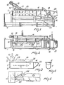
- Figure 1 is an elevation view of a machine which implements the inventive method;
- Figure 2 is a plan view of the same;
- Figure 3 is a longitudinal section view of the vibrating tank;
- Figure 4 is a cross-sectional view of the trough; and
- Figure 5 is an enlarged scale detail view in perspective.
- The machine which implements the inventive method comprises a
trough 1, which is generally stiffened both horizontally and vertically byribs - The trough has a substantially parallelepipedal shape in its upper portion, and a substantially semi-cylindrical one in its lower portion. It is further configuredwith a spout-
like outlet end 4 defined by a ramp-likeinclined portion 5 of the trough botton. 6 (Figure 3). Thetrough 1 is carried in a sprung manner by aframe 7, which encloses and supports vibration generators and related suspensions, as well as motors, which are known per se and no further discussed herein. - The workpieces to be treated are introduced at 9, through the
inlet end 8 of the trough. Located at saidinlet end 8 of the trough, there is provided ahopper 10 for introducing into the trough finishing bodies which, in this particular instance, comprise "rollable" finishing bodies, and nore specifically steel balls having a diameter dimension generally in the 1.6 to 6.5 mm range. For a more effective treatment, it is common practice to introduce into the cycle an assortment of balls of various sizes. Thehopper 10 is connected to an auger type ofconveyor 11 effective to re-cycle the finishing balls. The conveyor is driven by anelectric motor 12 and is set to slope downwardly toward thetrough outlet end 4. The terminatingportion 13 of the conveyor overlies thehopper 10, whereas theinitial portion 14 thereof is arranged with itshopper 15 below thescreen 16 separating the finishing balls from the treated workpieces. Thisscreen 16 is also arranged to vibrate, and provided with aspring suspension 17 andvibration generator 18. It is further provided with ascreening surface 19 formed with a suitable mesh size to let the balls through and withhold the treated workpieces. The latter are caused to advance toward theoutlet 20 of the screen wherefrom they are'collected while the balls fall along the inclined chute-likesurface 21 into thehopper 15 of theauger conveyor 11, which will move them toward its terminatingupper end 13 for re-cycling. - This part of the machine just described operates in a conventional manner for the art. After filling the trough with a mixture of workpieces and finishing balls in a preset optimum proportion and up to a preset level dependent also on the
edge 22 of thetrough discharge spout 4, the vibratory motion is initiated and the workpieces are subjected to a finishing process in a known manner while simultaneously advancing in the direction of the arrow A as far as thedischarge spout 4, whence the vibrating mass is discharged by overfalling past the weir head formed by thecorner edge 22 and onto thescreening deck 19 where the cited separation of the finishing balls from the treated workpieces takes place, the workpieces being then picked up and the balls cycled back through theauger conveyor 11. - The continuous cycle is then continued with the introduction of the finishing balls, from the
conveyor 11 and through thehopper 10, into the initial portion or leading portion of thetrough 1, as well as the introduction therein of fresh workpieces to be treated in accordance with a preset proportion, to thus resume the treatment cycle just described. - Now, it frequently occurs that the time duration of the treatment cycle is to be varied, that is the duration of the average time required for an average workpiece to complete the run from the trough.initial or leading portion to the outlet thereof must be varied, because some workpieces would require different duration treatments, as mentioned in the preamble.
- It has been found that this duration can be advantageously controlled by introducing an amount of finishing means, balls in the present case, into one or more locations in the proximity of the trough outlet portion.
- This amount taken from the mass of re-cycled balls form a sort of weir counterhead comparable to phenomena occurring in water downflows, which counterhead slows down the mass oncoming from upstream. It has been further ascertained that the slowing action is proportional to the amount of ball mass introduced in the proximity of the trough outlet portion.
- To provide such a weir counterhead and in accordance with one possible embodiment of the invention, a
distributor 24 is arranged at the outlet opening of thehopper 10 for re-introducing the finishing balls into the cycle. Thisdistributor 24. comprises a gated diverting mechanism 23 (Figure 5) which is associated with a duct orchannel 26 sloping in direction toward the spout end of the trough and being conveniently supported and axially slidable within limits to enable the lip gate to be inserted to a greater or lesser extent into thehopper 10, thereby a larger or smaller amount of finishing balls can be diverted toward theduct 26. Toward the opposite end, theduct 26 is formed on the bottom with one ormore openings 25 overlying and proximate the outlet zone of the trough, where through the diverted finishing balls are allowed to fall into the trough, and form said counterhead adapted to slow down the advance movement of the vibrating mass located upstream. - The operation of the apparatus is apparent from the foregoing description and will be summarized here below.
- After initiating the continuous cycle described hereinabove, and upon establishing that a batch of workpieces requires a longer duration treatment than the machine standard, the
duct 26 is slid axially toward thehopper 10, such that thediverting mechanism 23 can penetrate to a certain extent the interior of the passage defined by thehopper 10, as may be seen, for instance, in Figure 3. Thus, a part of the finishing balls will fall into the leading or initia.l portion of the vibrating trough and effect the treatment in a normal way, whereas the remaining part reaches the trough at the outlet zone thereof,thus forming a counterhead which slows down the advancing movement of the upstream mass. This slowing action is particularly exerted on the workpieces to be treated, which are more affected by the inflow of the ball mass introduced into the outlet zone of the trough and forming the counterhead. It has been found that as the amount of balls diverted to form the counterhead increases, the slowing action on the oncoming workpieces to be treated also increases, i.e. their time of residence in the trough increases so that it becomes possible to control or adjust the duration of said residence with adequate accuracy. Of course, the finishing balls to workpieces to be treated ratio will be maintained in the trough at an optimum value. - According to a further embodiment, instead of the auger conveyor, a belt elevator is provided which takes the finishing means up to a level above the trough and to the terminating portion thereof, where a horizontal belt conveyor is provided whereon the finishing means are deposited which are being delivered by the belt elevator, and which then conveys the finishing means toward the finishing means introduction hopper located at the trough inlet end. In this case, instead of the distributing duct, one or more diverters overlying the outlet end of the trough are provided which are operative to divert a part of the finishing means and deliver them into the trough, from the outlet end thereof, whereas the remaining part of the finishing means are transported by the horizontal belt conveyor toward the hopper located at the trough inlet end. This embodiment may be specially convenient for utilizing sharp edged finishing means as well.
- It will be appreciated from the foregoing that the objects set forth are fully achieved by the inventive method and apparatus, the scope whereof is more conveniently specified in the appended claims.
Claims (5)
1. A method for the vibrating mass treatment of metal surfaces, wherin there are introduced into the treatment cycle, at a starting zone (8) of the cycle, workpieces to be treated and finishing means forming together with the workpieces an incoherent mass which is then subjected to compounded vibrations having a finishing action component and a progressive incoherent mass advance action component, the action of said compounded vibration being protracted to carry out the workpieces finishing treatment and to urge the incoherent mass onwards along a prese-t path (A) at the end (4) whereof the finished workpieces and finishing means are separated, the finished workpieces being discharged and the finishing means cycled back, characterized in that a controlled part of the finishing means are let into said path (A) at one or more locations (25) in a zone downstream of the cycle remote from the starting zone (8) to form a counterhead effective to slow down the advance movement of the incoherent mass upstream.
2. A machine implementing the method according to Claim 1, comprising a vibrating treatment trough (1) defining a treatment path (A), the trough (1) having an inlet portion (8) and an outlet portion (5) for the incoherent treatment mass, means (10) for introducing said finishing means into said trough (1), in the zone of'the inlet portion (8) thereof for admixture with the workpieces to be treated introduced thereinto, treatment mass discharging means (21) located at the outlet portion (4) of the trough (1), means (19) for separating the finishing means from the treated workpieces, means for re-cycling the finishing means, and vibration generators (18) for the mass being treated, characterized in that it further comprises conveyor means (23, 26) for introducing said finishing means into said trough (1) in one or more locations in a zone downstream of the trough (1) inlet portion zone (8) and remote therefrom.
3. A machine according to Claim 2, characterized in that said conveyor means comprise at least one duct (26) arranged to overlie said treatment trough (1) and having one (23) end arranged to face the introduction means (10) for the finishing means and the other end (25) above the trough (1) outlet zone (4), the end (24) facing the finishing. means introduction means (10) being associated with a diverting member (23) adapted to controllably divert toward said duct (26) at least a part of the finishing balls let through said hopper (10), said duct (26) having one or more openings (25) overlying the trough outlet zone for discharging the finishing balls into said trough zone.
, 4. A machine according to Claims 2-3, characterized in.that said diverting member (24) is in the form of a gating element (23) associated with the conveying duct (26).
5. A machine according to Claim 2, characterized in that said conveyor means (11) comprise one or more diverting-means (24) cooperating with re-cycling means and diverting a part of the finishing means to be cycled back to the trough outlet end (4).
Applications Claiming Priority (2)
| Application Number | Priority Date | Filing Date | Title |
|---|---|---|---|
| IT2205381 | 1981-05-29 | ||
| IT22053/81A IT1136768B (en) | 1981-05-29 | 1981-05-29 | PROCESS AND EQUIPMENT FOR THE TREATMENT OF METAL SURFACES IN VIBRATING MASS, IN A CONTINUOUS CYCLE, WITH ADJUSTMENT OF THE DURATION OF THE TREATMENT |
Publications (1)
| Publication Number | Publication Date |
|---|---|
| EP0066007A1 true EP0066007A1 (en) | 1982-12-08 |
Family
ID=11190763
Family Applications (1)
| Application Number | Title | Priority Date | Filing Date |
|---|---|---|---|
| EP81108230A Withdrawn EP0066007A1 (en) | 1981-05-29 | 1981-10-12 | Method and apparatus for vibrating mass treatment of metal surfaces in a continuous cycle of controllable treatment time |
Country Status (5)
| Country | Link |
|---|---|
| EP (1) | EP0066007A1 (en) |
| ES (1) | ES8306628A1 (en) |
| GR (1) | GR76436B (en) |
| IT (1) | IT1136768B (en) |
| PT (1) | PT74327B (en) |
Cited By (1)
| Publication number | Priority date | Publication date | Assignee | Title |
|---|---|---|---|---|
| WO2023150991A1 (en) * | 2022-02-11 | 2023-08-17 | 湖北雄志塑胶五金制品有限公司 | Vibration grinding machine |
Citations (5)
| Publication number | Priority date | Publication date | Assignee | Title |
|---|---|---|---|---|
| US3071900A (en) * | 1959-12-30 | 1963-01-08 | Gunther W Balz | Continuous finishing and polishing machine |
| US3337997A (en) * | 1965-03-24 | 1967-08-29 | John F Rampe | Finishing apparatus |
| US3685213A (en) * | 1970-02-05 | 1972-08-22 | Rampe Research | Orbital finishing system |
| US3831322A (en) * | 1970-02-05 | 1974-08-27 | Rampe Research | Continuous feed vibratory finishing machine with discharge rate controlled by operation of tub discharge closure |
| US4254586A (en) * | 1979-03-30 | 1981-03-10 | King-Seeley Thermos Co. | Time cycle control system for vibratory finishing machines |
-
1981
- 1981-05-29 IT IT22053/81A patent/IT1136768B/en active
- 1981-10-12 EP EP81108230A patent/EP0066007A1/en not_active Withdrawn
-
1982
- 1982-01-22 PT PT74327A patent/PT74327B/en unknown
- 1982-02-22 GR GR67361A patent/GR76436B/el unknown
- 1982-02-27 ES ES509984A patent/ES8306628A1/en not_active Expired
Patent Citations (5)
| Publication number | Priority date | Publication date | Assignee | Title |
|---|---|---|---|---|
| US3071900A (en) * | 1959-12-30 | 1963-01-08 | Gunther W Balz | Continuous finishing and polishing machine |
| US3337997A (en) * | 1965-03-24 | 1967-08-29 | John F Rampe | Finishing apparatus |
| US3685213A (en) * | 1970-02-05 | 1972-08-22 | Rampe Research | Orbital finishing system |
| US3831322A (en) * | 1970-02-05 | 1974-08-27 | Rampe Research | Continuous feed vibratory finishing machine with discharge rate controlled by operation of tub discharge closure |
| US4254586A (en) * | 1979-03-30 | 1981-03-10 | King-Seeley Thermos Co. | Time cycle control system for vibratory finishing machines |
Cited By (1)
| Publication number | Priority date | Publication date | Assignee | Title |
|---|---|---|---|---|
| WO2023150991A1 (en) * | 2022-02-11 | 2023-08-17 | 湖北雄志塑胶五金制品有限公司 | Vibration grinding machine |
Also Published As
| Publication number | Publication date |
|---|---|
| ES509984A0 (en) | 1983-06-16 |
| PT74327A (en) | 1982-02-01 |
| PT74327B (en) | 1984-10-29 |
| ES8306628A1 (en) | 1983-06-16 |
| IT1136768B (en) | 1986-09-03 |
| GR76436B (en) | 1984-08-10 |
| IT8122053A0 (en) | 1981-05-29 |
Similar Documents
| Publication | Publication Date | Title |
|---|---|---|
| CH617002A5 (en) | ||
| EP0066007A1 (en) | Method and apparatus for vibrating mass treatment of metal surfaces in a continuous cycle of controllable treatment time | |
| US2003430A (en) | Apparatus for removing magnetic from nonmagnetic material | |
| WO2007027090A2 (en) | Apparatus for separating solids from a liquid | |
| US2618373A (en) | Tobacco arranging machine | |
| US3685213A (en) | Orbital finishing system | |
| JPS57209743A (en) | Method and device for treating recovered sand | |
| US2747735A (en) | Endless belt magnetic separator | |
| AT403519B (en) | DEVICE FOR APPLYING SINTER MATERIAL TO AN ALREADY IGNITED SINTER BASE LAYER | |
| DE3517309A1 (en) | Apparatus for separating a bulk material mixture into fractions having equal specific gravity | |
| US4127480A (en) | Settling machine | |
| EP0049404B1 (en) | Method and device for the treatment of workpieces by abrasive blasting | |
| GB380196A (en) | Improved process and apparatus for removing dust from coal | |
| US3290836A (en) | Method of surface finishing articles | |
| DE3169186D1 (en) | Process and device for discharging a bunker with a slot-like outlet funnel | |
| EP0391213A2 (en) | Storage hopper, especially for vibrating feeders | |
| RU2187389C2 (en) | Gravitational separator | |
| DE940434C (en) | Device for separating curd and whey using a sieve | |
| DE3148728C1 (en) | Device for washing out organic and clay-like impurities from continuously supplied coarse and fine-grained solids | |
| US2413976A (en) | Machine for continuous dry powdering or curing seeds and grain | |
| DE3034451A1 (en) | Decomposing plant for unset concrete - has constant diameter rotary drum with spiral strips discharging into drag buckets | |
| US2137679A (en) | Process of separating a mass of seeds of varied characteristics | |
| US3328922A (en) | Apparatus for surface finishing articles | |
| EP0770428A1 (en) | Flotation plant with cyclic liquid volume variation | |
| SU956013A1 (en) | Magnetic separator |
Legal Events
| Date | Code | Title | Description |
|---|---|---|---|
| PUAI | Public reference made under article 153(3) epc to a published international application that has entered the european phase |
Free format text: ORIGINAL CODE: 0009012 |
|
| AK | Designated contracting states |
Designated state(s): AT BE CH DE FR GB LU NL SE |
|
| 17P | Request for examination filed |
Effective date: 19830524 |
|
| STAA | Information on the status of an ep patent application or granted ep patent |
Free format text: STATUS: THE APPLICATION IS DEEMED TO BE WITHDRAWN |
|
| 18D | Application deemed to be withdrawn |
Effective date: 19850816 |
|
| RIN1 | Information on inventor provided before grant (corrected) |
Inventor name: COLOMBO, GIOVANNI Inventor name: PIVK, GIUSEPPE |