EP0072237A2 - Apparatus for scanning a sheet - Google Patents
Apparatus for scanning a sheet Download PDFInfo
- Publication number
- EP0072237A2 EP0072237A2 EP82304196A EP82304196A EP0072237A2 EP 0072237 A2 EP0072237 A2 EP 0072237A2 EP 82304196 A EP82304196 A EP 82304196A EP 82304196 A EP82304196 A EP 82304196A EP 0072237 A2 EP0072237 A2 EP 0072237A2
- Authority
- EP
- European Patent Office
- Prior art keywords
- waveform
- sheet
- strip
- banknote
- light
- Prior art date
- Legal status (The legal status is an assumption and is not a legal conclusion. Google has not performed a legal analysis and makes no representation as to the accuracy of the status listed.)
- Granted
Links
- 230000015654 memory Effects 0.000 claims abstract description 38
- 239000000835 fiber Substances 0.000 claims description 10
- 230000001419 dependent effect Effects 0.000 claims 1
- 239000013307 optical fiber Substances 0.000 abstract description 8
- 238000003909 pattern recognition Methods 0.000 abstract description 4
- 238000000034 method Methods 0.000 description 8
- 238000010606 normalization Methods 0.000 description 6
- 238000001228 spectrum Methods 0.000 description 6
- 239000003086 colorant Substances 0.000 description 5
- 230000001934 delay Effects 0.000 description 5
- 238000010586 diagram Methods 0.000 description 5
- 238000001514 detection method Methods 0.000 description 4
- 238000012545 processing Methods 0.000 description 4
- 238000005259 measurement Methods 0.000 description 3
- 238000004458 analytical method Methods 0.000 description 2
- 230000003287 optical effect Effects 0.000 description 2
- 230000035945 sensitivity Effects 0.000 description 2
- 239000002689 soil Substances 0.000 description 2
- 238000013459 approach Methods 0.000 description 1
- 238000003491 array Methods 0.000 description 1
- 238000006073 displacement reaction Methods 0.000 description 1
- 230000000694 effects Effects 0.000 description 1
- 230000006870 function Effects 0.000 description 1
- 238000005286 illumination Methods 0.000 description 1
- 239000000463 material Substances 0.000 description 1
- 238000012544 monitoring process Methods 0.000 description 1
- 230000004044 response Effects 0.000 description 1
- 238000005070 sampling Methods 0.000 description 1
- 230000003595 spectral effect Effects 0.000 description 1
Images


Classifications
-
- G—PHYSICS
- G07—CHECKING-DEVICES
- G07D—HANDLING OF COINS OR VALUABLE PAPERS, e.g. TESTING, SORTING BY DENOMINATIONS, COUNTING, DISPENSING, CHANGING OR DEPOSITING
- G07D7/00—Testing specially adapted to determine the identity or genuineness of valuable papers or for segregating those which are unacceptable, e.g. banknotes that are alien to a currency
- G07D7/06—Testing specially adapted to determine the identity or genuineness of valuable papers or for segregating those which are unacceptable, e.g. banknotes that are alien to a currency using wave or particle radiation
- G07D7/12—Visible light, infrared or ultraviolet radiation
- G07D7/121—Apparatus characterised by sensor details
-
- G—PHYSICS
- G07—CHECKING-DEVICES
- G07D—HANDLING OF COINS OR VALUABLE PAPERS, e.g. TESTING, SORTING BY DENOMINATIONS, COUNTING, DISPENSING, CHANGING OR DEPOSITING
- G07D7/00—Testing specially adapted to determine the identity or genuineness of valuable papers or for segregating those which are unacceptable, e.g. banknotes that are alien to a currency
- G07D7/06—Testing specially adapted to determine the identity or genuineness of valuable papers or for segregating those which are unacceptable, e.g. banknotes that are alien to a currency using wave or particle radiation
- G07D7/12—Visible light, infrared or ultraviolet radiation
- G07D7/1205—Testing spectral properties
-
- G—PHYSICS
- G07—CHECKING-DEVICES
- G07D—HANDLING OF COINS OR VALUABLE PAPERS, e.g. TESTING, SORTING BY DENOMINATIONS, COUNTING, DISPENSING, CHANGING OR DEPOSITING
- G07D7/00—Testing specially adapted to determine the identity or genuineness of valuable papers or for segregating those which are unacceptable, e.g. banknotes that are alien to a currency
- G07D7/181—Testing mechanical properties or condition, e.g. wear or tear
- G07D7/187—Detecting defacement or contamination, e.g. dirt
-
- G—PHYSICS
- G07—CHECKING-DEVICES
- G07D—HANDLING OF COINS OR VALUABLE PAPERS, e.g. TESTING, SORTING BY DENOMINATIONS, COUNTING, DISPENSING, CHANGING OR DEPOSITING
- G07D7/00—Testing specially adapted to determine the identity or genuineness of valuable papers or for segregating those which are unacceptable, e.g. banknotes that are alien to a currency
- G07D7/20—Testing patterns thereon
Definitions
- the present invention relates to optical apparatus for scanning a sheet, and is particularly useful for analysing the surfaces of banknotes.
- the apparatus may respond to the overall condition of the note, for example the degree of soiling of the note, or it may be used for pattern recognition; for example to sort banknotes in accordance with their orientation and their denomination or Bank of Origin.
- the multi-detector system In order to identify banknotes reliably the multi-detector system usually employs a high resolution, i.e. the pixel size is small.
- the disadvantage of using a small pixel size is that a great deal of information is obtained for each banknote scanned and if the data processing time is to be kept within useful limits the processing must be accomplished in a highly sophisticated manner. It is difficult to process the data in the time available between banknotes, when scanning at the rate of 20-30 notes per second (a common speed for banknote transport systems), with presently available digital processing systems. It is also very expensive. It is therefore an object of the present invention to provide a simple form of apparatus for scanning a sheet in which a waveform characteristic of the surface of the sheet may be produced easily, even if the sheet is worn or soiled.
- Apparatus according to the invention for scanning a sheet comprises: means for illuminating the sheet; means for collecting light from an illuminated strip of the sheet; means responsive to the light collected from all regions of the strip to produce a summed intensity signal; means for moving the sheet relative to the light collector in a direction substantially perpendicular to the strip; and analysing means responsive to successive summed intensity signals to create a waveform which is characteristic of the surface of the sheet.
- the means responsive to the collected light is preferably a single photodetector, and the means for collecting light from the strip is preferably a fibre optic fishtail array, the wide end of which is arranged adjacent to the strip, and the narrow end of which delivers light to the photodetector.
- the sheet is preferably illuminated with white light, the means responsive to collected light having a spectral response similar to that of the human eye.
- the means for illuminating the strip may also be a fibre optic fishtail array, with a source of white light or blue-white light positioned next to the narrow end of the fishtail array, and the wide end of the fishtail arranged adjacent to the said strip so that light will be reflected in the strip and reach the photodetector.
- a lengthwise strip of the banknote surface is illuminated, and the banknote is moved in a direction parallel to its width.
- the apparatus may be arranged to illuminate a strip that is longer than the length of the banknote, with light from the whole of this length being delivered to the photodetector, in order that variations in the position of the banknote, in a direction perpendicular to the scanning direction, as it passes the scanning apparatus do not affect the waveform produced.
- This system is also insensitive to any printing registration errors in a direction along the strip of the banknote.
- the illuminated strip is in the centre of the sheet, so that a central band of the sheet is scanned by the scanner.
- the same band of the sheet is scanned no matter which way round the sheet is fed into the apparatus.
- the waveform is simply reversed for opposite orientations of the sheet.
- the sheet may, however, be scanned by two strip scanners arranged across the sheet, so that two parallel bands of the sheet are scanned. These bands are preferably of equal width and are equidistant from the centre of the sheet, so that changing the orientation of the sheet simply results in the same two bands being scanned in reverse, resulting in the waveforms from the two strip scanners being interchanged and reversed.
- a memory is provided to store each waveform from each of the scanners.
- the preferred apparatus incorporates a memory for storing the characteristic waveform of a sheet for subsequent comparison with another sheet.
- the apparatus then works in two alternative modes, the first mode being for recording the waveform in the memory, and the second mode being for comparing a currently-produced waveform with a stored waveform. Different waveforms are produced depending on the two possible orientations of a sheet as it passes the scanner. It is a preferred additional feature that when in the compare mode the apparatus should make a simultaneous comparison of the currently-produced waveform with a reversed stored waveform. The waveform is therefore compared with two waveforms, corresponding to the two possible orientations of the sheet.
- the waveform produced by this apparatus as a function of time depends on the width of the sheet being scanned, given that the speed of scan is constant.
- a sheet that is skewed as it enters the scanning apparatus would produce a slightly longer waveform, which, when compared with a stored waveform characteristic of the same type of banknote, would fail to correlate. This failure would also occur for banknotes which are slightly stretched or shrunken.
- a further aspect of the invention is in the provision of a circuit for determining the mean level of the said successive summed intensity signals, and comparing each successive summed intensity signal with the said mean level.
- the differences between the signal level and the mean level are preferably squared, summed, and then square-rooted, so as to provide a signal representing the standard deviation of the successive summed intensity signals from the mean.
- This standard deviation signal is directly related to the age and the degree of soiling of the material of the sheet, the standard deviation being lowest for sheets having the poorest condition.
- the apparatus for scanning a sheet preferably produces a large number of successive summed intensity signals during the scan. These signals may be all in respect of light of the same spectrum, but a refinement of the apparatus is possible by using a colour detector.
- Such colour detection apparatus comprises: means for illuminating the sheet; means for collecting light from an illuminated strip of the sheet; means responsive to the light collected from all regions of the strip to provide a set of colour intensity signals, each representative of the intensity of a different group of wavelengths of the collected light; means for moving the sheet relative to the light collector in a direction substantially perpendicular to the strip; and analysing means responsive to successive summed colour intensity signals to create waveforms for each colour, the waveforms being characteristic of the surface of the sheet.
- the apparatus preferably incorporates a memory for storing the characteristic colour waveforms of a sheet for subsequent comparison with respective waveforms of another sheet, as has been described above for single colour comparison.
- the apparatus then works in two alternative modes, the first mode being for recording the waveforms in the memory, and the second mode being for comparing currently-produced waveforms with stored waveforms, to determine the stored waveform which produces the best match.
- each waveform is preferably compared with two stored waveforms, corresponding to the two possible orientations of the sheet.
- This colour detection apparatus may for example comprise a plurality of photodetectors responsive to the different wavelengths of light, each photodetector arranged to receive light from the said collecting means. Successive summed intensity signals are preferably taken from each photodetector in rotation, so that the summed intensity for any given wavelength is sampled periodically during the scan.
- eight wavelengths are monitored sixteen times during each scan across a banknote, the total number of successive summed intensity signals being 128. It is preferable to normalize the length of the characteristic waveform of each colour separately, to ensure that regions of a scanned banknote are compared with corresponding regions of a standard banknote, on the basis of the same group of wavelengths.
- a banknote 33, Figure 1 is illuminated with white light or blue-white light from an array of optical fibre bundles and light reflected from the surface is collected by an array of receiving fibre bundles. Visible light is used when this apparatus is used in conjunction with a soil detection system, because it has been found that this gives the most reliable results, particularly when banknotes are soiled with a yellow colour.
- the optical detector simulates a human sorter who works in daylight or fluorescent light.
- An optical fibre fishtail array is particularly useful both for illuminating a strip of the banknote and for collecting light reflected from the same strip. Two such fishtail arrays are used in the present embodiment.
- An optical fibre fishtail array consists of a group of adjacent bundles of fibres, the bundles being bunched together to have a common light input at one end, the bundles fanning out so that the other ends of the bundles are spaced in a regular linear array.
- a single detector or light source at the narrow end of the group thus communicates with each end of respective optical fibre bundles.
- the receiving fibre optic fishtail is arranged to collect light diffusely reflected from the banknote surface.
- the system is then largely insensitive to the presence of shiny transparent tape on banknotes.
- the banknote 33 to be scanned is mounted on a rotating drum.
- the detector head includes a lamp, a first optical fibre fishtail array for directing light onto a strip of the surface of the banknote 33, and a second optical fibre fishtail array for collecting light reflected from the surface and for conveying it to a photodetector.
- Figure 1 is a block circuit diagram of apparatus according to a first embodiment of the invention. It incorporates a detector head 1 arranged over the path of a banknote 33. Successive summed intensity waveforms from lengthwise strips of the banknote 33 are fed through a filter 2 to a first delay 3 and a comparator 4.
- a clock generatorand counter 8 controlled by control logic 13 causes the waveform represented by successive signals from the filter 2 to be clocked into the first delay 3.
- the comparator 4 compares the waveform from filter 2 with an input threshold level in order to determine the beginning and the end of the waveform representing the banknote 33.
- the output of the comparator 4 is fed into the control logic 13 which in turn controls the clock generator and counter 8.
- the clock generator 8 responds to the length of the waveform to adjust, the clock frequency accordingly so that the waveform is clocked into a second delay 6 via another filter 5 at a greater or lesser frequency. All waveforms clocked into the second delay 6 are adjusted to be of the same standard length. This compensation for length may be achieved as follows. Suppose that the first and second delays 3, 6 both have a capacity of N T bits, and that the length of the waveform is such as to occupy only the first N W bits in the first delay 3 (the size N T of the delays is designed so that for all input waveform lengths N W ⁇ N T ). The waveform is then expanded so that it fills exactly all N T bits of the second delay 6, and is thus expanded into a standard length.
- the N W bits were counted and stored in a register. This information determines the ratio between the frequencies of clocking out from the first delay 3 and clocking in to the second delay 6.
- the waveform is clocked out of the first delay at a frequency f 1 while the stored digital number N W is loaded into a down counter in the clock generator and counter 8.
- the down counter is reduced to a zero count by counting at a higher frequency f 2 , and produces a single pulse on reaching zero. This occurs each time it is required to clock the waveform portion into the second delay 6, so the single pulse is a clocking pulse for loading the expanded waveform into the second delay 6, at a clocking frequency of F 2 ⁇ N W .
- the number N W is reloaded into the down counter, and the process is repeated, so as to provide a regular series of single pulses for clocking the second delay 6, until it is full with N T bits.
- the time taken to fill the second delay 6 is equal to the number of bits, N T , divided by the clocking frequency, and is therefore equal to
- the number of bits read out from the first delay 3 in this time is then: which should of course be equal to N w .
- f 2 must be made equal to f x NT, regardless of the waveform.
- Waveforms emerging from the first delay 3 and the second delay 6 are filtered by filters 5 and 7 respectively, to remove clock frequency components.
- Each delay unit comprises a series of analogue stores and processes the analogue signals by sampling the voltage present at the input and clocking this value into the first analogue store and thence from store to store until the final store.
- the first and second delays have been replaced by a single delay 3, with its associated filter 5 for removing the clock pulses from the signal.
- the clock generator clocks the waveform into the delay, and the comparator 4 and control logic 13 determine the length of the waveform as for the circuit of Figure 1.
- the waveform is clocked in to the delay 3 at a fixed rate, but is clocked out, and processed simultaneously by the remainder of the circuit, at a variable rate.
- the variable clocking out rate is determined by means of a voltage-to-frequency converter 42 which is fed by the voltage from a digital-to-analogue converter 41 responsive to a signal from'the control logic 13 representing the length of the waveform.
- the section of the circuit responsible for determining the age and/or degree of soiling of the banknote is to be found at the top and right-hand corner of Figure 1.
- the mean value of the waveform is determined by an integrator 9 which is operated by _the control logic 13.
- a predetermined portion of the waveform is integrated under the control of the control logic 13 which operates switches 10 and 11.
- Switch 10 connects the integrator 9 to receive the signal from the filter 5, and switch 11 operates to reset the integrator to zero. The further operation of this part of the circuit will be described below.
- the normalised waveform emerges from the filter 7 ( Figure 1) or filter 5 ( Figure 2).
- this output is recorded in a memory 16 in digital form. Recording is achieved by means of a staircase generator 12 and a comparator 14.
- Comparator 14 compares the normalised waveform with successively larger levels of potential produced by the staircase generator 12 under control by the clock generator 8 and control logic 13. The output of comparator 14 is thus in digital form, and represents successive levels of the waveform. In this example, the digitisation is performed 128 times during the passing of the waveform, but smaller or larger numbers can be adopted for different applications.
- the normalised waveform from the filter 7 is compared with the waveform stored in the memory 16, the latter having been converted into analogue form in a digital-to-analogue converter 15.
- the overall level of the waveform from a subsequent banknote may be higher than the overall level stored in the memory, even though the characteristics of the waveforms are identical. It is therefore preferable to compensate for any overall differences in level.
- This can be achieved in the circuit of Figure 1 by converter controlling the output of the digital-to-analogue/l5 in accordance with the mean value of the waveform derived by the integrator 9. If the current mean value of the integrator 9 is higher than normal, then the signals derived from memory 16 should be correspondingly increased in level.
- the waveform from the filter could be reduced in level.
- a fair comparison of the current and stored waveforms is made in a differential squarer 17. The difference is squared, and the output from the differential squarer 17 is fed into a sample-and-hold unit 20.
- the waveform of the banknote currently being scanned should also ideally be compared with the reverse of the stored waveform in memory 16. It will then not matter whether the banknote is orientated in one way or the other. To achieve this, the signal from the digital-to-analogue converter 15 alternates between the value corresponding to the true memory address and the value corresponding to the inverted memory address.
- the output of the differential squarer 17 therefore alternates between the true comparison and the reverse comparison, and the output is summed alternately by sample-and-hold units 20 and 21, under the control logic 13.
- Sample-and-hold amplifiers 20, 21 are switched alternately according to whether the true or inverted memory address is chosen.
- the inverted address of the portion of the waveform at the opposite end is determined easily, simply by subtracting the true address from the size of the memory. In binary, this may simply be the equivalent of changing the sign of the address, i.e. inverting the binary address number. In an eight bit memory, for example, an address 010 would be inverted to 101.
- the outputs of these sample-and-hold units 20, 21 are integrated in integrators 18, 19 respectively, so as to produce a signal representing the sum of the squares of the differences between the current waveform and the stored waveform.
- a square-rooting device 29 is switched in unison with these two outputs and the output of the square-rooting device is fed to two comparators 22; 23 alternately.
- These comparators 22, 23 produce outputs according to whether the true or inverted waveforms respectively agree with the stored waveform within a tolerance level fixed by a preset threshold signal. Generally, of course, one of these outputs will exceed the threshold level and the other will be below it.
- These output signals are then used by external apparatus (not shown) to route the banknote according to its orientation and/or its pattern.
- the output from the integrator 9 representing the mean value is compared with the output of the filter 7 ( Figure 1) or filter 5 ( Figure 2) representing the normalised waveform.
- This comparison is made in another differential squarer 24 at each of the 128 scanning points. The difference is squared, sampled in a sample-and-hold unit 25, integrated in an integrator 26 and then square-rooted in a unit 27 before being compared in a further comparator 28 with a predetermined threshold.
- the output from the square-rooter unit 27 is indicative of the standard deviation of the waveform from the mean level. A large standard deviation indicates a new banknote with very little soiling.
- the output of the final comparator 28 is used to route the banknote in accordance with its age and/or its degree of soiling.
- items 15 to 23 and 29 of the diagram of Figure 1 can be duplicated, together with their control logic circuitry, so that the system can be programmed to recognise any one of a number of different document patterns, as stored in different memories 16.
- This pattern recognition can be conducted simultaneously. In this way it is possible to compare a banknote simultaneously with a number of possible banknotes, for example. By comparing the outputs from all of the integrators 18, 19 and deciding which one exhibits the lowest value, the stored pattern matching the input waveform most closely can be chosen, and the banknote can be routed accordingly.
- FIGS 3 and 4 show a second embodiment of the invention in which the apparatus is refined by separately analysing light of different wavelengths.
- a detector head is provided with one photodetector for each of the wavelengths required, each photodetector receiving light from the same optical fibre fishtail array.
- this colour detector head with for example eight photodetectors corresponding to eight different wavelengths of light, each wavelength can be monitored sixteen times with a 128 scan system. Each colour is then compared with a corresponding value in the memory, for a number of discrete areas scanned sequentially as the note passes.
- the layout of the detector head is shown in Figure 3.
- Light from a wide band source 101 is focused on to the moving banknote 102.
- the reflected light is passed through a spectroscope 103 and lens 104 which splits the light into a spectrum.
- the spectrum falls onto the photodetectors which constitute a photodiode array 105, or similar detecting means, so that each detecting element of the array measures the intensity of light at a selected group of wavelengths.
- the output of each of these detecting elements is transmitted along a separate channel to respective amplifier 108 ( Figure 4).
- a suitable detector head is also described in our UK copending application N0.2078368A, published 6th January 1982.
- FIG 4 shows a signal processing unit which responds to the colour signals and diverts the detected banknote in accordance with a correlation of its colour pattern with two or more stored colour patterns.
- This circuit is very similar to the circuit of Figure 1 with the exception that there are several channels from the detector head, one for each colour, and that the single memory 16 is replaced by two (or more) memories 128, 129 for a corresponding number of banknote patterns.
- Each length normalization unit 109 includes one or two delays which are controlled in the manner described above.
- the soil detection section (9, 10, 11, 24-28, Figure 1) has not been included in the circuit of Figure 4 , but it could be incorporated.
- a control circuit 132 responds to a signal from the detector head 107 indicative of the presence of a banknote, and controls several other elements of the circuit, as indicated in the figure by "control" inputs.
- the amplifiers 108 for each colour channel provide colour intensity signal outputs to length normalisation units 109 of which there is one per channel, each functioning in the manner described above with reference to the analogue delay or delays 3, 6 ( Figure 1 or Figure 2).
- a first mode of operation of the apparatus successive signals from each colour channel are stored in the memory 128 or 129.
- the memory therefore stores a measurement of the colour spectrum at each successive scanned point.
- the apparatus responds to colour signals from a target banknote to correlate the signals units, in order to determine the best match.
- a method of performing this comparison, colour by colour is described in our British copending application No.2078368A, referred to above, In that prior specification, the method produced an error signal if the sample and standard waveforms did not agree within specified tolerances; in the present circuit, the main purpose is to produce a correlation signal for each comparison and to determine the highest correlation, i.e. the best match.
- the size of the strip which is scanned can be varied to only a small degree in the direction of movement of the banknote, since it is not usually of advantage to allow successive strips to overlap, but the width of the strip (in a direction at right-angles to the direction of movement) is variable up to or in excess of, the length of the banknote. If the area monitored is greater than the length of the banknote, then any movement of the banknote at right-angles to the scan motion does not affect the measurement made, since the detector always indicates the colour characteristics across the area monitored.
- the detector head must be placed centrally over the banknote. It is necessary to normalise the length of the waveforms from the banknote in order that the pattern reversal is achieved simply. There may alternatively be two detector heads monitoring the banknote along lines equidistant from the central line of the banknote in the direction of motion.
- the signals from the sample banknote obtained from the two detectors can either be compared with a single stored standard representing the colour pattern on one selected side, with reversal as explained above where necessary and a match from either detector looked for, or else the signals from the two heads can each be compared with two standards representing the pattern on each side of the banknote, with reversals as appropriate, and a match against either pattern looked for on both detectors.
- the memory units 128, 129 store the pattern for two standard banknotes.
- the length normalisation circuits 109 ensure that the lengths monitored are the same on each banknote, and that the memory addresses in the memory units 128, 129 are completely filled for all banknotes, so that reversal of the pattern can be achieved simply by inverting the memory addresses.
- Signals from the different amplifiers 108 for different colours may be monitored simultaneously, so that each strip is scanned for all the colours.
- the characteristic waveforms produced in each colour channel may be expanded or contracted by the same factor. It is preferable, however, to monitor colour signals sequentially, so that a different strip of the banknote is scanned for each colour, the signals from the amplifiers 108 being sampled cyclically as the banknote is scanned along its width.
- banknotes of different widths which are otherwise identical would not necessarily produce characteristic waveforms which matched for all the colours, if the same expansion factor were applied for all the colours in the normalization process. This is because the total number of samples from any banknote may be different for different colours.
- the scan may start always with one particular colour, but the last colour scanned depends on the length of the pattern on the banknote. In this case, therefore, the normalization must be made separately for each colour channel. This ensures that regions of a scanned banknote are compared with corresponding regions of a standard banknote, on the basis of the same group of wavelengths.
- the various colour channels are multiplexed in a multiplexer unit 110 and fed to an analogue-to- digital converter 111, when the apparatus is being operated in the first mode (for storing the standard patterns).
- analogue-to- digital converter 111 When a standard pattern is being recorded in this way, the output from the converter unit 111, consisting of a number of lines of digital information, is written into one of the two memories 128, 129.
- the outputs from the memories 128, 129 are reconverted into analogue form by the converters 113, l14 and subtracted from the sample colour waveforms from the multiplexer unit 110 by the subtract and squaring circuits 115, 116.
- the colour signals from the multiplexer unit 110 are also fed to a mean level assessment unit 112 to provide a reference voltage indicative of the mean intensity level of each colour.
- This mean level is used to adjust the outputs from the memory to such a level whereby a fair comparison can be made with the incoming colour signals from the multiplexer unit 110. Any differences in intensity which affect the whole spectrum are compensated for by this method.
- the outputs from the subtract and squaring circuit 115, 116 are switched by the control circuitry 132 in electronic switches 117, 118 to sample-and-hold circuits 119, 120, 121 and 122, according to whether the true or the reversed pattern is being compared, and these outputs are then summed by the integrators 123, 124, 125 and 126.
- a comparison is made with a corresponding stored signal from each memory unit and on the basis of each possible orientation of the banknote.
- the electronic switches 117, 118 alternate in the same way that the comparisons are alternated between the true and the reversed patterns.
- Sample-and-hold amplifier 119 therefore stores the result of the comparison with the true pattern from memory 128, while sample-and-hold amplifier 120 stores the results of the comparisons with the reversed pattern of memory 128.
- Sample-and-hold amplifiers 121 and 122 store the corresponding results for the comparisons with the true and reversed patterns in memory 129.
- the outputs from the integrators are switched, by the control circuitry, sequentially to the square root circuit 131 at the end of the comparison.
- the output which represents the square root of the sum of the squares of the differences of the sample and standard objects, is fed to the best match processor unit 130, for each of the banknotes and orientations sequentially.
- This processor compares these signals, which are in effect the standard deviations of the sample from the standard object, and selects the best match. In accordance with this best match, data for either rejecting the banknote or for diverting it to one or more destinations, is then fed to the object's transport system so that its progress can be suitably controlled.
- the number of memory units 128, 129 for storing data for standard banknotes can be increased, together with the associated subtract and square circuits, sample-and-hold amplifiers and so on.
- the "best match" from all the standard banknotes, taken at either orientation, can then be obtained in an analogous manner.
- a banknote is scanned by means of visible light reflected from its surface.
- Other embodiments of the invention are envisaged, in which light transmitted through a sheet is detected by a strip scanner.
- the spectrum of light used does not have to be in the visible region; for the scanning of watermarks in a banknote, for example, it may be preferable to use ultra-violet light.
- the wavelength of the light source may be chosen to enhance differences in the waveforms of the patterns of banknote types that are similar in white light.
- the means for illuminating the strip of the banknote should preferably be such that the width of the illuminated strip of note can be altered. This enables the waveform that is characteristic of a particular note to be altered simply by changing the resolution of the sensor head and is particularly useful where one type of banknote is to be identified from other having'similar designs.
- a variable resolution can be achieved by using an illumination fibre optic fishtail constructed of fibres with a large numerical aperture.
- the divergence of the output beam which determines the resolution of the head, is controlled by collimating to a greater or lesser extent the input light source to the fibres. (The divergence of the input beam to a fibre determines the divergence of the output beam from the fibre, within the confines of the numerical aperture of the fibre).
Abstract
Description
- The present invention relates to optical apparatus for scanning a sheet, and is particularly useful for analysing the surfaces of banknotes. The apparatus may respond to the overall condition of the note, for example the degree of soiling of the note, or it may be used for pattern recognition; for example to sort banknotes in accordance with their orientation and their denomination or Bank of Origin.
- We have previously proposed apparatus for scanning banknotes, to analyse their condition or to recognise patterns on their surface, including a plurality of discrete detectors arranged across the banknote. Signals from each of the detectors are processed independently until the final stages of analysis in which some comparison may be made between the levels of intensity from each detector. For the purpose of banknote pattern recognition this approach has several significant disadvantages:
- (i) sensitivity to lateral displacement of banknotes with respect to the detector head;
- (ii) sensitivity to printing variations, such as: the misregister of one layer of print with respect to another (the printing of a banknote normally involves several separate printing processes); and the misregister of the whole pattern with respect to the edges of a banknote.
- In order to identify banknotes reliably the multi-detector system usually employs a high resolution, i.e. the pixel size is small. The disadvantage of using a small pixel size is that a great deal of information is obtained for each banknote scanned and if the data processing time is to be kept within useful limits the processing must be accomplished in a highly sophisticated manner. It is difficult to process the data in the time available between banknotes, when scanning at the rate of 20-30 notes per second (a common speed for banknote transport systems), with presently available digital processing systems. It is also very expensive. It is therefore an object of the present invention to provide a simple form of apparatus for scanning a sheet in which a waveform characteristic of the surface of the sheet may be produced easily, even if the sheet is worn or soiled.
- Apparatus according to the invention for scanning a sheet comprises: means for illuminating the sheet; means for collecting light from an illuminated strip of the sheet; means responsive to the light collected from all regions of the strip to produce a summed intensity signal; means for moving the sheet relative to the light collector in a direction substantially perpendicular to the strip; and analysing means responsive to successive summed intensity signals to create a waveform which is characteristic of the surface of the sheet. The means responsive to the collected light is preferably a single photodetector, and the means for collecting light from the strip is preferably a fibre optic fishtail array, the wide end of which is arranged adjacent to the strip, and the narrow end of which delivers light to the photodetector. The sheet is preferably illuminated with white light, the means responsive to collected light having a spectral response similar to that of the human eye. The means for illuminating the strip may also be a fibre optic fishtail array, with a source of white light or blue-white light positioned next to the narrow end of the fishtail array, and the wide end of the fishtail arranged adjacent to the said strip so that light will be reflected in the strip and reach the photodetector.
- In the preferred embodiment of the invention for scanning banknotes, a lengthwise strip of the banknote surface is illuminated, and the banknote is moved in a direction parallel to its width. The apparatus may be arranged to illuminate a strip that is longer than the length of the banknote, with light from the whole of this length being delivered to the photodetector, in order that variations in the position of the banknote, in a direction perpendicular to the scanning direction, as it passes the scanning apparatus do not affect the waveform produced. This system is also insensitive to any printing registration errors in a direction along the strip of the banknote. In an alternative arrangement, the illuminated strip is in the centre of the sheet, so that a central band of the sheet is scanned by the scanner. Then the same band of the sheet is scanned no matter which way round the sheet is fed into the apparatus. The waveform is simply reversed for opposite orientations of the sheet. The sheet may, however, be scanned by two strip scanners arranged across the sheet, so that two parallel bands of the sheet are scanned. These bands are preferably of equal width and are equidistant from the centre of the sheet, so that changing the orientation of the sheet simply results in the same two bands being scanned in reverse, resulting in the waveforms from the two strip scanners being interchanged and reversed. In this form of the apparatus, a memory is provided to store each waveform from each of the scanners.
- The preferred apparatus incorporates a memory for storing the characteristic waveform of a sheet for subsequent comparison with another sheet. The apparatus then works in two alternative modes, the first mode being for recording the waveform in the memory, and the second mode being for comparing a currently-produced waveform with a stored waveform. Different waveforms are produced depending on the two possible orientations of a sheet as it passes the scanner. It is a preferred additional feature that when in the compare mode the apparatus should make a simultaneous comparison of the currently-produced waveform with a reversed stored waveform. The waveform is therefore compared with two waveforms, corresponding to the two possible orientations of the sheet.
- The waveform produced by this apparatus as a function of time depends on the width of the sheet being scanned, given that the speed of scan is constant. In the case of banknotes, for example, a sheet that is skewed as it enters the scanning apparatus would produce a slightly longer waveform, which, when compared with a stored waveform characteristic of the same type of banknote, would fail to correlate. This failure would also occur for banknotes which are slightly stretched or shrunken. It is a preferred feature of the invention to compensate for the different lengths of waveforms produced in the apparatus, by a circuit which measures the length of the waveform and either compresses or expands the waveform until it has a standard length.
- A further aspect of the invention is in the provision of a circuit for determining the mean level of the said successive summed intensity signals, and comparing each successive summed intensity signal with the said mean level. The differences between the signal level and the mean level are preferably squared, summed, and then square-rooted, so as to provide a signal representing the standard deviation of the successive summed intensity signals from the mean. This standard deviation signal is directly related to the age and the degree of soiling of the material of the sheet, the standard deviation being lowest for sheets having the poorest condition.
- The apparatus for scanning a sheet preferably produces a large number of successive summed intensity signals during the scan. These signals may be all in respect of light of the same spectrum, but a refinement of the apparatus is possible by using a colour detector.
- Such colour detection apparatus comprises: means for illuminating the sheet; means for collecting light from an illuminated strip of the sheet; means responsive to the light collected from all regions of the strip to provide a set of colour intensity signals, each representative of the intensity of a different group of wavelengths of the collected light; means for moving the sheet relative to the light collector in a direction substantially perpendicular to the strip; and analysing means responsive to successive summed colour intensity signals to create waveforms for each colour, the waveforms being characteristic of the surface of the sheet. The apparatus preferably incorporates a memory for storing the characteristic colour waveforms of a sheet for subsequent comparison with respective waveforms of another sheet, as has been described above for single colour comparison. The apparatus then works in two alternative modes, the first mode being for recording the waveforms in the memory, and the second mode being for comparing currently-produced waveforms with stored waveforms, to determine the stored waveform which produces the best match. As before, each waveform is preferably compared with two stored waveforms, corresponding to the two possible orientations of the sheet.
- This colour detection apparatus may for example comprise a plurality of photodetectors responsive to the different wavelengths of light, each photodetector arranged to receive light from the said collecting means. Successive summed intensity signals are preferably taken from each photodetector in rotation, so that the summed intensity for any given wavelength is sampled periodically during the scan. In the preferred form of apparatus including such a colour detector head, eight wavelengths are monitored sixteen times during each scan across a banknote, the total number of successive summed intensity signals being 128. It is preferable to normalize the length of the characteristic waveform of each colour separately, to ensure that regions of a scanned banknote are compared with corresponding regions of a standard banknote, on the basis of the same group of wavelengths.
- In order that the invention may be better understood, two preferred embodiments of the invention are described below with reference to the accompanying drawings, wherein:-
- Figure 1 is a block circuit diagram of apparatus according to an embodiment of the invention for recognising the characteristic pattern on the surface of a banknote and for detecting the age and/or degree of soiling of the banknote;
- Figure 2 is a block diagram of a different waveform length normalizing section which could be used in the circuit of Figure 1 as an alternative;
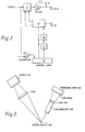
- Figure 3 is a sketch of the detecting head layout of a colour pattern scanner in accordance with another preferred embodiment; and
- Figure 4 is a block diagram of the detecting and analysing section of the apparatus of the other embodiment.
- A
banknote 33, Figure 1, is illuminated with white light or blue-white light from an array of optical fibre bundles and light reflected from the surface is collected by an array of receiving fibre bundles. Visible light is used when this apparatus is used in conjunction with a soil detection system, because it has been found that this gives the most reliable results, particularly when banknotes are soiled with a yellow colour. In this respect, the optical detector simulates a human sorter who works in daylight or fluorescent light. An optical fibre fishtail array is particularly useful both for illuminating a strip of the banknote and for collecting light reflected from the same strip. Two such fishtail arrays are used in the present embodiment. An optical fibre fishtail array consists of a group of adjacent bundles of fibres, the bundles being bunched together to have a common light input at one end, the bundles fanning out so that the other ends of the bundles are spaced in a regular linear array. A single detector or light source at the narrow end of the group thus communicates with each end of respective optical fibre bundles. - In the preferred embodiment of the invention the receiving fibre optic fishtail is arranged to collect light diffusely reflected from the banknote surface. The system is then largely insensitive to the presence of shiny transparent tape on banknotes.
- The
banknote 33 to be scanned is mounted on a rotating drum. The detector head includes a lamp, a first optical fibre fishtail array for directing light onto a strip of the surface of thebanknote 33, and a second optical fibre fishtail array for collecting light reflected from the surface and for conveying it to a photodetector. - Figure 1 is a block circuit diagram of apparatus according to a first embodiment of the invention. It incorporates a detector head 1 arranged over the path of a
banknote 33. Successive summed intensity waveforms from lengthwise strips of thebanknote 33 are fed through afilter 2 to afirst delay 3 and acomparator 4. Aclock generatorand counter 8 controlled bycontrol logic 13 causes the waveform represented by successive signals from thefilter 2 to be clocked into thefirst delay 3. Thecomparator 4 compares the waveform fromfilter 2 with an input threshold level in order to determine the beginning and the end of the waveform representing thebanknote 33. The output of thecomparator 4 is fed into thecontrol logic 13 which in turn controls the clock generator andcounter 8. In this way, theclock generator 8 responds to the length of the waveform to adjust, the clock frequency accordingly so that the waveform is clocked into asecond delay 6 via anotherfilter 5 at a greater or lesser frequency. All waveforms clocked into thesecond delay 6 are adjusted to be of the same standard length. This compensation for length may be achieved as follows. Suppose that the first andsecond delays second delay 6, and is thus expanded into a standard length. - While the waveform was clocked into the first delay, at a frequency fo, the NW bits were counted and stored in a register. This information determines the ratio between the frequencies of clocking out from the
first delay 3 and clocking in to thesecond delay 6. The waveform is clocked out of the first delay at a frequency f1 while the stored digital number NW is loaded into a down counter in the clock generator andcounter 8. The down counter is reduced to a zero count by counting at a higher frequency f2, and produces a single pulse on reaching zero. This occurs each time it is required to clock the waveform portion into thesecond delay 6, so the single pulse is a clocking pulse for loading the expanded waveform into thesecond delay 6, at a clocking frequency of F2 ÷ NW. On producing the single pulse, the number NW is reloaded into the down counter, and the process is repeated, so as to provide a regular series of single pulses for clocking thesecond delay 6, until it is full with NT bits. - The time taken to fill the
second delay 6 is equal to the number of bits, NT, divided by the clocking frequency, and is therefore equal to
first delay 3 in this time is then:
- Waveforms emerging from the
first delay 3 and thesecond delay 6 are filtered byfilters 5 and 7 respectively, to remove clock frequency components. - Each delay unit comprises a series of analogue stores and processes the analogue signals by sampling the voltage present at the input and clocking this value into the first analogue store and thence from store to store until the final store.
- In an alternative circuit of which the length normalization unit is shown in Figure 2, the first and second delays have been replaced by a
single delay 3, with its associatedfilter 5 for removing the clock pulses from the signal. The clock generator clocks the waveform into the delay, and thecomparator 4 and controllogic 13 determine the length of the waveform as for the circuit of Figure 1. The waveform is clocked in to thedelay 3 at a fixed rate, but is clocked out, and processed simultaneously by the remainder of the circuit, at a variable rate. The variable clocking out rate is determined by means of a voltage-to-frequency converter 42 which is fed by the voltage from a digital-to-analogue converter 41 responsive to a signalfrom'the control logic 13 representing the length of the waveform. The following description applies equally to both the Figure 1 and the Figure 2 circuits. - The section of the circuit responsible for determining the age and/or degree of soiling of the banknote is to be found at the top and right-hand corner of Figure 1. The mean value of the waveform is determined by an integrator 9 which is operated by
_the control logic 13. A predetermined portion of the waveform is integrated under the control of thecontrol logic 13 which operatesswitches 10 and 11.Switch 10 connects the integrator 9 to receive the signal from thefilter 5, and switch 11 operates to reset the integrator to zero. The further operation of this part of the circuit will be described below. - The normalised waveform, with the standard length, emerges from the filter 7 (Figure 1) or filter 5 (Figure 2). When the apparatus is in "record" mode, this output is recorded in a
memory 16 in digital form. Recording is achieved by means of astaircase generator 12 and acomparator 14.Comparator 14 compares the normalised waveform with successively larger levels of potential produced by thestaircase generator 12 under control by theclock generator 8 and controllogic 13. The output ofcomparator 14 is thus in digital form, and represents successive levels of the waveform. In this example, the digitisation is performed 128 times during the passing of the waveform, but smaller or larger numbers can be adopted for different applications. - With the apparatus in the "comparison" mode, the normalised waveform from the filter 7 is compared with the waveform stored in the
memory 16, the latter having been converted into analogue form in a digital-to-analogue converter 15. The overall level of the waveform from a subsequent banknote may be higher than the overall level stored in the memory, even though the characteristics of the waveforms are identical. It is therefore preferable to compensate for any overall differences in level. This can be achieved in the circuit of Figure 1 by converter controlling the output of the digital-to-analogue/l5 in accordance with the mean value of the waveform derived by the integrator 9. If the current mean value of the integrator 9 is higher than normal, then the signals derived frommemory 16 should be correspondingly increased in level. Alternatively, of course, the waveform from the filter (5 or 7) could be reduced in level. A fair comparison of the current and stored waveforms is made in adifferential squarer 17. The difference is squared, and the output from the differential squarer 17 is fed into a sample-and-hold unit 20. The waveform of the banknote currently being scanned should also ideally be compared with the reverse of the stored waveform inmemory 16. It will then not matter whether the banknote is orientated in one way or the other. To achieve this, the signal from the digital-to-analogue converter 15 alternates between the value corresponding to the true memory address and the value corresponding to the inverted memory address. The output of the differential squarer 17 therefore alternates between the true comparison and the reverse comparison, and the output is summed alternately by sample-and-hold units control logic 13. Sample-and-hold amplifiers hold units integrators device 29 is switched in unison with these two outputs and the output of the square-rooting device is fed to twocomparators 22; 23 alternately. Thesecomparators - To return now to the section of the circuit responsible for determining the age and/or degree of soiling of the banknote, the output from the integrator 9 representing the mean value is compared with the output of the filter 7 (Figure 1) or filter 5 (Figure 2) representing the normalised waveform. This comparison is made in another differential squarer 24 at each of the 128 scanning points. The difference is squared, sampled in a sample-and-
hold unit 25, integrated in anintegrator 26 and then square-rooted in aunit 27 before being compared in afurther comparator 28 with a predetermined threshold. The output from the square-rooter unit 27 is indicative of the standard deviation of the waveform from the mean level. A large standard deviation indicates a new banknote with very little soiling. The output of thefinal comparator 28 is used to route the banknote in accordance with its age and/or its degree of soiling. - As an extension of the system,
items 15 to 23 and 29 of the diagram of Figure 1 can be duplicated, together with their control logic circuitry, so that the system can be programmed to recognise any one of a number of different document patterns, as stored indifferent memories 16. This pattern recognition can be conducted simultaneously. In this way it is possible to compare a banknote simultaneously with a number of possible banknotes, for example. By comparing the outputs from all of theintegrators - Figures 3 and 4 show a second embodiment of the invention in which the apparatus is refined by separately analysing light of different wavelengths. A detector head is provided with one photodetector for each of the wavelengths required, each photodetector receiving light from the same optical fibre fishtail array. Using this colour detector head, with for example eight photodetectors corresponding to eight different wavelengths of light, each wavelength can be monitored sixteen times with a 128 scan system. Each colour is then compared with a corresponding value in the memory, for a number of discrete areas scanned sequentially as the note passes.
- The layout of the detector head is shown in Figure 3. Light from a
wide band source 101 is focused on to the movingbanknote 102. The reflected light is passed through aspectroscope 103 andlens 104 which splits the light into a spectrum. The spectrum falls onto the photodetectors which constitute aphotodiode array 105, or similar detecting means, so that each detecting element of the array measures the intensity of light at a selected group of wavelengths. The output of each of these detecting elements is transmitted along a separate channel to respective amplifier 108 (Figure 4). A suitable detector head is also described in our UK copending application N0.2078368A, published 6th January 1982. - Figure 4 shows a signal processing unit which responds to the colour signals and diverts the detected banknote in accordance with a correlation of its colour pattern with two or more stored colour patterns. This circuit is very similar to the circuit of Figure 1 with the exception that there are several channels from the detector head, one for each colour, and that the
single memory 16 is replaced by two (or more)memories length normalization unit 109 includes one or two delays which are controlled in the manner described above. The soil detection section (9, 10, 11, 24-28, Figure 1) has not been included in the circuit of Figure 4, but it could be incorporated. Acontrol circuit 132 responds to a signal from thedetector head 107 indicative of the presence of a banknote, and controls several other elements of the circuit, as indicated in the figure by "control" inputs. Theamplifiers 108 for each colour channel provide colour intensity signal outputs tolength normalisation units 109 of which there is one per channel, each functioning in the manner described above with reference to the analogue delay ordelays 3, 6 (Figure 1 or Figure 2). - In a first mode of operation of the apparatus, successive signals from each colour channel are stored in the
memory - The size of the strip which is scanned can be varied to only a small degree in the direction of movement of the banknote, since it is not usually of advantage to allow successive strips to overlap, but the width of the strip (in a direction at right-angles to the direction of movement) is variable up to or in excess of, the length of the banknote. If the area monitored is greater than the length of the banknote, then any movement of the banknote at right-angles to the scan motion does not affect the measurement made, since the detector always indicates the colour characteristics across the area monitored.
- As described above, it is possible to detect banknotes fed through the system in either orientation, by comparing the waveform with a reversed standard waveform as well as with the standard waveform. Where there is only one scanned strip, the detector head must be placed centrally over the banknote. It is necessary to normalise the length of the waveforms from the banknote in order that the pattern reversal is achieved simply. There may alternatively be two detector heads monitoring the banknote along lines equidistant from the central line of the banknote in the direction of motion. The signals from the sample banknote obtained from the two detectors can either be compared with a single stored standard representing the colour pattern on one selected side, with reversal as explained above where necessary and a match from either detector looked for, or else the signals from the two heads can each be compared with two standards representing the pattern on each side of the banknote, with reversals as appropriate, and a match against either pattern looked for on both detectors.
- The
memory units length normalisation circuits 109 ensure that the lengths monitored are the same on each banknote, and that the memory addresses in thememory units - Signals from the
different amplifiers 108 for different colours may be monitored simultaneously, so that each strip is scanned for all the colours. In this case, the characteristic waveforms produced in each colour channel may be expanded or contracted by the same factor. It is preferable, however, to monitor colour signals sequentially, so that a different strip of the banknote is scanned for each colour, the signals from theamplifiers 108 being sampled cyclically as the banknote is scanned along its width. In this case, banknotes of different widths which are otherwise identical would not necessarily produce characteristic waveforms which matched for all the colours, if the same expansion factor were applied for all the colours in the normalization process. This is because the total number of samples from any banknote may be different for different colours. The scan may start always with one particular colour, but the last colour scanned depends on the length of the pattern on the banknote. In this case, therefore, the normalization must be made separately for each colour channel. This ensures that regions of a scanned banknote are compared with corresponding regions of a standard banknote, on the basis of the same group of wavelengths. - The various colour channels are multiplexed in a
multiplexer unit 110 and fed to an analogue-to-digital converter 111, when the apparatus is being operated in the first mode (for storing the standard patterns). When a standard pattern is being recorded in this way, the output from theconverter unit 111, consisting of a number of lines of digital information, is written into one of the twomemories - In the comparison mode, the outputs from the
memories converters 113, l14 and subtracted from the sample colour waveforms from themultiplexer unit 110 by the subtract and squaringcircuits multiplexer unit 110 are also fed to a meanlevel assessment unit 112 to provide a reference voltage indicative of the mean intensity level of each colour. This mean level is used to adjust the outputs from the memory to such a level whereby a fair comparison can be made with the incoming colour signals from themultiplexer unit 110. Any differences in intensity which affect the whole spectrum are compensated for by this method. - The outputs from the subtract and squaring
circuit control circuitry 132 inelectronic switches hold circuits integrators electronic switches hold amplifier 119 therefore stores the result of the comparison with the true pattern frommemory 128, while sample-and-hold amplifier 120 stores the results of the comparisons with the reversed pattern ofmemory 128. Sample-and-hold amplifiers memory 129. The outputs from the integrators are switched, by the control circuitry, sequentially to thesquare root circuit 131 at the end of the comparison. The output, which represents the square root of the sum of the squares of the differences of the sample and standard objects, is fed to the bestmatch processor unit 130, for each of the banknotes and orientations sequentially. This processor compares these signals, which are in effect the standard deviations of the sample from the standard object, and selects the best match. In accordance with this best match, data for either rejecting the banknote or for diverting it to one or more destinations, is then fed to the object's transport system so that its progress can be suitably controlled. - The number of
memory units - In the embodiments of the invention described above, a banknote is scanned by means of visible light reflected from its surface. Other embodiments of the invention, however, are envisaged, in which light transmitted through a sheet is detected by a strip scanner. Moreover, the spectrum of light used does not have to be in the visible region; for the scanning of watermarks in a banknote, for example, it may be preferable to use ultra-violet light. The wavelength of the light source may be chosen to enhance differences in the waveforms of the patterns of banknote types that are similar in white light.
- In any of the embodiments described above, the means for illuminating the strip of the banknote should preferably be such that the width of the illuminated strip of note can be altered. This enables the waveform that is characteristic of a particular note to be altered simply by changing the resolution of the sensor head and is particularly useful where one type of banknote is to be identified from other having'similar designs.
- A variable resolution can be achieved by using an illumination fibre optic fishtail constructed of fibres with a large numerical aperture. The divergence of the output beam, which determines the resolution of the head, is controlled by collimating to a greater or lesser extent the input light source to the fibres. (The divergence of the input beam to a fibre determines the divergence of the output beam from the fibre, within the confines of the numerical aperture of the fibre).
Claims (15)
Priority Applications (1)
| Application Number | Priority Date | Filing Date | Title |
|---|---|---|---|
| AT82304196T ATE26892T1 (en) | 1981-08-11 | 1982-08-09 | DEVICE FOR SCANNING DOCUMENTS. |
Applications Claiming Priority (4)
| Application Number | Priority Date | Filing Date | Title |
|---|---|---|---|
| GB8124501 | 1981-08-11 | ||
| GB8124501 | 1981-08-11 | ||
| GB8133280 | 1981-11-04 | ||
| GB8133280 | 1981-11-04 |
Publications (3)
| Publication Number | Publication Date |
|---|---|
| EP0072237A2 true EP0072237A2 (en) | 1983-02-16 |
| EP0072237A3 EP0072237A3 (en) | 1983-07-06 |
| EP0072237B1 EP0072237B1 (en) | 1987-04-29 |
Family
ID=26280417
Family Applications (1)
| Application Number | Title | Priority Date | Filing Date |
|---|---|---|---|
| EP82304196A Expired EP0072237B1 (en) | 1981-08-11 | 1982-08-09 | Apparatus for scanning a sheet |
Country Status (6)
| Country | Link |
|---|---|
| US (1) | US4592090A (en) |
| EP (1) | EP0072237B1 (en) |
| CA (1) | CA1190651A (en) |
| DE (1) | DE3276200D1 (en) |
| DK (1) | DK360782A (en) |
| NO (1) | NO822718L (en) |
Cited By (17)
| Publication number | Priority date | Publication date | Assignee | Title |
|---|---|---|---|---|
| EP0101115A1 (en) * | 1982-07-20 | 1984-02-22 | Nederlandse Organisatie voor toegepast-natuurwetenschappelijk onderzoek TNO | A device for recognising and examining bank-notes or the like |
| WO1985002928A1 (en) * | 1983-12-27 | 1985-07-04 | Bergstroem Arne | Apparatus for authenticating bank notes |
| WO1986001923A1 (en) * | 1984-09-11 | 1986-03-27 | De La Rue Systems Limited | Apparatus for sensing the condition of a document |
| EP0246832A2 (en) * | 1986-05-19 | 1987-11-25 | Marconi Instruments Limited | Pattern Alignment generator |
| FR2600191A1 (en) * | 1986-06-17 | 1987-12-18 | Laurel Bank Machine Co | PAPER COINS DISCRIMINATOR |
| US5116037A (en) * | 1991-04-08 | 1992-05-26 | Landis & Gyr Betriebs Ag | Apparatus for receiving and issuing sheets |
| US5139149A (en) * | 1990-08-06 | 1992-08-18 | Landis & Gyr Betriebs Ag | Apparatus for stacking sheets |
| EP0613104A1 (en) * | 1991-10-08 | 1994-08-31 | Kabushiki Kaisha Ace Denken | Changing machine having function of judging wear of bill |
| EP0660277A2 (en) * | 1993-12-27 | 1995-06-28 | Azkoyen Industrial, S.A. | Method and apparatus for the characterization and discrimination of legal tender bank notes and documents |
| US5569015A (en) * | 1991-05-08 | 1996-10-29 | Mars Incorporated | Intermediate storage apparatus |
| US5711649A (en) * | 1991-05-08 | 1998-01-27 | Mars Incorporated | Sheet stacking apparatus |
| ES2145711A1 (en) * | 1998-07-09 | 2000-07-01 | Nacional Moneda Timbre | Process and device for the optical/electronic detection and decoding of barcode watermarks |
| EP1178441A2 (en) * | 2000-06-21 | 2002-02-06 | Giesecke & Devrient GmbH | Method for determination of structural inhomogeneities in sheets |
| US7672499B2 (en) | 1990-02-05 | 2010-03-02 | Cummins-Allison Corp. | Method and apparatus for currency discrimination and counting |
| US8871333B2 (en) | 2003-05-22 | 2014-10-28 | Ian MacMillan Ward | Interlayer hot compaction |
| EP2880597A4 (en) * | 2012-07-31 | 2016-03-23 | De Rue North America Inc | Systems and methods for spectral authentication of a feature of a document |
| EP1158459B2 (en) † | 2000-05-16 | 2017-02-15 | Sicpa Holding Sa | Method, device and security system, all for authenticating a marking |
Families Citing this family (120)
| Publication number | Priority date | Publication date | Assignee | Title |
|---|---|---|---|---|
| US4845610A (en) * | 1984-07-13 | 1989-07-04 | Ford Aerospace & Communications Corporation | Target recognition using string-to-string matching |
| US5023923A (en) * | 1987-02-11 | 1991-06-11 | Light Signatures, Inc. | Programmable sensor aperture |
| US4922110A (en) * | 1988-04-15 | 1990-05-01 | Brandt, Inc. | Document counter and endorser |
| US4947441A (en) * | 1988-05-20 | 1990-08-07 | Laurel Bank Machine Co., Ltd. | Bill discriminating apparatus |
| DE3819900A1 (en) * | 1988-06-11 | 1989-12-14 | Daimler Benz Ag | METHOD FOR DETERMINING THE CORROSION STABILITY OF DEEP-DRAWABLE IRON SHEETS FOR BODY PARTS OF MOTOR VEHICLES, AND DEVICE FOR CARRYING OUT THIS METHOD |
| GB8918699D0 (en) * | 1989-08-16 | 1989-09-27 | De La Rue Syst | Thread detector assembly |
| US5003189A (en) * | 1989-10-10 | 1991-03-26 | Unisys Corp. | Document-imaging illumination with fibre-optic intensity-adjust |
| US5259043A (en) * | 1989-10-10 | 1993-11-02 | Unisys Corporation | Filtering illumination for image lift |
| US5089713A (en) * | 1989-10-10 | 1992-02-18 | Unisys Corporation | Document-imaging illumination arrangements with intensity with adjustment |
| US6913130B1 (en) * | 1996-02-15 | 2005-07-05 | Cummins-Allison Corp. | Method and apparatus for document processing |
| US6311819B1 (en) | 1996-05-29 | 2001-11-06 | Cummins-Allison Corp. | Method and apparatus for document processing |
| US5905810A (en) * | 1990-02-05 | 1999-05-18 | Cummins-Allison Corp. | Automatic currency processing system |
| US5875259A (en) | 1990-02-05 | 1999-02-23 | Cummins-Allison Corp. | Method and apparatus for discriminating and counting documents |
| US5966456A (en) * | 1990-02-05 | 1999-10-12 | Cummins-Allison Corp. | Method and apparatus for discriminating and counting documents |
| US5815592A (en) * | 1990-02-05 | 1998-09-29 | Cummins-Allison Corp. | Method and apparatus for discriminating and counting documents |
| US5960103A (en) * | 1990-02-05 | 1999-09-28 | Cummins-Allison Corp. | Method and apparatus for authenticating and discriminating currency |
| US5870487A (en) * | 1990-02-05 | 1999-02-09 | Cummins-Allison Corp. | Method and apparatus for discriminting and counting documents |
| US5724438A (en) * | 1990-02-05 | 1998-03-03 | Cummins-Allison Corp. | Method of generating modified patterns and method and apparatus for using the same in a currency identification system |
| US5790693A (en) * | 1990-02-05 | 1998-08-04 | Cummins-Allison Corp. | Currency discriminator and authenticator |
| US5633949A (en) * | 1990-02-05 | 1997-05-27 | Cummins-Allison Corp. | Method and apparatus for currency discrimination |
| US6539104B1 (en) | 1990-02-05 | 2003-03-25 | Cummins-Allison Corp. | Method and apparatus for currency discrimination |
| US5992601A (en) * | 1996-02-15 | 1999-11-30 | Cummins-Allison Corp. | Method and apparatus for document identification and authentication |
| US6959800B1 (en) | 1995-12-15 | 2005-11-01 | Cummins-Allison Corp. | Method for document processing |
| US6636624B2 (en) | 1990-02-05 | 2003-10-21 | Cummins-Allison Corp. | Method and apparatus for currency discrimination and counting |
| US5751840A (en) * | 1990-02-05 | 1998-05-12 | Cummins-Allison Corp. | Method and apparatus for currency discrimination |
| US7248731B2 (en) * | 1992-05-19 | 2007-07-24 | Cummins-Allison Corp. | Method and apparatus for currency discrimination |
| US5652802A (en) * | 1990-02-05 | 1997-07-29 | Cummins-Allison Corp. | Method and apparatus for document identification |
| US5790697A (en) * | 1990-02-05 | 1998-08-04 | Cummins-Allion Corp. | Method and apparatus for discriminating and counting documents |
| US5467406A (en) * | 1990-02-05 | 1995-11-14 | Cummins-Allison Corp | Method and apparatus for currency discrimination |
| US6241069B1 (en) | 1990-02-05 | 2001-06-05 | Cummins-Allison Corp. | Intelligent currency handling system |
| JPH03285459A (en) * | 1990-03-31 | 1991-12-16 | Canon Inc | Picture reader |
| SE9100612L (en) * | 1991-02-06 | 1992-08-07 | Lauzun Corp | HYBRID DRIVE SYSTEM FOR MOTOR VEHICLE |
| GB9120848D0 (en) * | 1991-10-01 | 1991-11-13 | Innovative Tech Ltd | Banknote validator |
| ES2103330T3 (en) * | 1991-10-14 | 1997-09-16 | Mars Inc | DEVICE FOR OPTICAL RECOGNITION OF DOCUMENTS. |
| US6866134B2 (en) * | 1992-05-19 | 2005-03-15 | Cummins-Allison Corp. | Method and apparatus for document processing |
| US6915893B2 (en) * | 2001-04-18 | 2005-07-12 | Cummins-Alliston Corp. | Method and apparatus for discriminating and counting documents |
| US6220419B1 (en) | 1994-03-08 | 2001-04-24 | Cummins-Allison | Method and apparatus for discriminating and counting documents |
| US6980684B1 (en) | 1994-04-12 | 2005-12-27 | Cummins-Allison Corp. | Method and apparatus for discriminating and counting documents |
| US6628816B2 (en) | 1994-08-09 | 2003-09-30 | Cummins-Allison Corp. | Method and apparatus for discriminating and counting documents |
| US5982918A (en) * | 1995-05-02 | 1999-11-09 | Cummins-Allison, Corp. | Automatic funds processing system |
| US6748101B1 (en) | 1995-05-02 | 2004-06-08 | Cummins-Allison Corp. | Automatic currency processing system |
| US6363164B1 (en) | 1996-05-13 | 2002-03-26 | Cummins-Allison Corp. | Automated document processing system using full image scanning |
| US6278795B1 (en) | 1995-12-15 | 2001-08-21 | Cummins-Allison Corp. | Multi-pocket currency discriminator |
| US6880692B1 (en) | 1995-12-15 | 2005-04-19 | Cummins-Allison Corp. | Method and apparatus for document processing |
| ES2108647B1 (en) * | 1995-12-21 | 1998-07-01 | Azkoyen Ind Sa | METHOD AND APPARATUS FOR THE CHARACTERIZATION AND DISCRIMINATION OF TICKETS AND LEGAL COURSE DOCUMENTS. |
| GB2309299B (en) | 1996-01-16 | 2000-06-07 | Mars Inc | Sensing device |
| US8950566B2 (en) | 1996-05-13 | 2015-02-10 | Cummins Allison Corp. | Apparatus, system and method for coin exchange |
| US6661910B2 (en) | 1997-04-14 | 2003-12-09 | Cummins-Allison Corp. | Network for transporting and processing images in real time |
| US7903863B2 (en) | 2001-09-27 | 2011-03-08 | Cummins-Allison Corp. | Currency bill tracking system |
| US7232024B2 (en) | 1996-05-29 | 2007-06-19 | Cunnins-Allison Corp. | Currency processing device |
| US8162125B1 (en) | 1996-05-29 | 2012-04-24 | Cummins-Allison Corp. | Apparatus and system for imaging currency bills and financial documents and method for using the same |
| US7187795B2 (en) | 2001-09-27 | 2007-03-06 | Cummins-Allison Corp. | Document processing system using full image scanning |
| US20050276458A1 (en) | 2004-05-25 | 2005-12-15 | Cummins-Allison Corp. | Automated document processing system and method using image scanning |
| US6860375B2 (en) * | 1996-05-29 | 2005-03-01 | Cummins-Allison Corporation | Multiple pocket currency bill processing device and method |
| PE73298A1 (en) * | 1996-06-04 | 1998-11-13 | Coin Bill Validator Inc | BANK TICKET VALIDATOR |
| US6026175A (en) * | 1996-09-27 | 2000-02-15 | Cummins-Allison Corp. | Currency discriminator and authenticator having the capability of having its sensing characteristics remotely altered |
| US7584883B2 (en) * | 1996-11-15 | 2009-09-08 | Diebold, Incorporated | Check cashing automated banking machine |
| US7559460B2 (en) * | 1996-11-15 | 2009-07-14 | Diebold Incorporated | Automated banking machine |
| US5923413A (en) * | 1996-11-15 | 1999-07-13 | Interbold | Universal bank note denominator and validator |
| US7513417B2 (en) * | 1996-11-15 | 2009-04-07 | Diebold, Incorporated | Automated banking machine |
| US6573983B1 (en) | 1996-11-15 | 2003-06-03 | Diebold, Incorporated | Apparatus and method for processing bank notes and other documents in an automated banking machine |
| US8478020B1 (en) | 1996-11-27 | 2013-07-02 | Cummins-Allison Corp. | Apparatus and system for imaging currency bills and financial documents and method for using the same |
| KR100353515B1 (en) * | 1997-04-16 | 2002-12-18 | 가부시끼가이샤 닛본 콘럭스 | Bill discriminating method and bill discrimination apparatus |
| AU7159098A (en) | 1997-05-07 | 1998-11-27 | Cummins-Allison Corp. | Intelligent currency handling system |
| US6039645A (en) * | 1997-06-24 | 2000-03-21 | Cummins-Allison Corp. | Software loading system for a coin sorter |
| US5940623A (en) * | 1997-08-01 | 1999-08-17 | Cummins-Allison Corp. | Software loading system for a coin wrapper |
| JP3655451B2 (en) * | 1997-12-11 | 2005-06-02 | 富士通株式会社 | Paper sheet identification device |
| US6493461B1 (en) | 1998-03-17 | 2002-12-10 | Cummins-Allison Corp. | Customizable international note counter |
| GB9806914D0 (en) * | 1998-03-31 | 1998-05-27 | Rue De Int Ltd | Methods and apparatus for monitoring articles |
| US6064058A (en) * | 1998-05-15 | 2000-05-16 | Hung-Yi Wu | Printed paper identification system |
| US6040584A (en) * | 1998-05-22 | 2000-03-21 | Mti Corporation | Method and for system for detecting damaged bills |
| WO2000065546A1 (en) | 1999-04-28 | 2000-11-02 | Cummins-Allison Corp. | Currency processing machine with multiple coin receptacles |
| US6637576B1 (en) | 1999-04-28 | 2003-10-28 | Cummins-Allison Corp. | Currency processing machine with multiple internal coin receptacles |
| DE19958048A1 (en) * | 1999-12-03 | 2001-06-07 | Giesecke & Devrient Gmbh | Device and method for checking the authenticity of banknotes |
| US6473165B1 (en) | 2000-01-21 | 2002-10-29 | Flex Products, Inc. | Automated verification systems and methods for use with optical interference devices |
| US6335501B1 (en) * | 2000-02-04 | 2002-01-01 | Eco-Shred Ltd. | Optical paper sorter |
| AU2001234955A1 (en) * | 2000-02-08 | 2001-08-20 | Cummins-Allison Corp. | Method and apparatus for detecting doubled bills in a currency handling device |
| US6398000B1 (en) | 2000-02-11 | 2002-06-04 | Cummins-Allison Corp. | Currency handling system having multiple output receptacles |
| US6588569B1 (en) | 2000-02-11 | 2003-07-08 | Cummins-Allison Corp. | Currency handling system having multiple output receptacles |
| US6601687B1 (en) | 2000-02-11 | 2003-08-05 | Cummins-Allison Corp. | Currency handling system having multiple output receptacles |
| US8701857B2 (en) | 2000-02-11 | 2014-04-22 | Cummins-Allison Corp. | System and method for processing currency bills and tickets |
| DE10007887A1 (en) * | 2000-02-21 | 2001-08-23 | Giesecke & Devrient Gmbh | Method and device for checking the authenticity of printed objects |
| GB2361765A (en) * | 2000-04-28 | 2001-10-31 | Ncr Int Inc | Media validation by diffusely reflected light |
| US6546351B1 (en) | 2000-07-20 | 2003-04-08 | Currency Systems International | Note-specific currency processing |
| GB0025096D0 (en) * | 2000-10-13 | 2000-11-29 | Bank Of England | Detection of printing and coating media |
| US7647275B2 (en) | 2001-07-05 | 2010-01-12 | Cummins-Allison Corp. | Automated payment system and method |
| US8437530B1 (en) | 2001-09-27 | 2013-05-07 | Cummins-Allison Corp. | Apparatus and system for imaging currency bills and financial documents and method for using the same |
| US8433123B1 (en) | 2001-09-27 | 2013-04-30 | Cummins-Allison Corp. | Apparatus and system for imaging currency bills and financial documents and method for using the same |
| US8944234B1 (en) | 2001-09-27 | 2015-02-03 | Cummins-Allison Corp. | Apparatus and system for imaging currency bills and financial documents and method for using the same |
| US8437529B1 (en) | 2001-09-27 | 2013-05-07 | Cummins-Allison Corp. | Apparatus and system for imaging currency bills and financial documents and method for using the same |
| US8428332B1 (en) | 2001-09-27 | 2013-04-23 | Cummins-Allison Corp. | Apparatus and system for imaging currency bills and financial documents and method for using the same |
| US6896118B2 (en) | 2002-01-10 | 2005-05-24 | Cummins-Allison Corp. | Coin redemption system |
| US6913260B2 (en) * | 2002-03-06 | 2005-07-05 | Cummins-Allison Corp. | Currency processing system with fitness detection |
| US7158662B2 (en) * | 2002-03-25 | 2007-01-02 | Cummins-Allison Corp. | Currency bill and coin processing system |
| US7551764B2 (en) * | 2002-03-25 | 2009-06-23 | Cummins-Allison Corp. | Currency bill and coin processing system |
| US7269279B2 (en) * | 2002-03-25 | 2007-09-11 | Cummins-Allison Corp. | Currency bill and coin processing system |
| US6970236B1 (en) | 2002-08-19 | 2005-11-29 | Jds Uniphase Corporation | Methods and systems for verification of interference devices |
| US8171567B1 (en) | 2002-09-04 | 2012-05-01 | Tracer Detection Technology Corp. | Authentication method and system |
| US8627939B1 (en) | 2002-09-25 | 2014-01-14 | Cummins-Allison Corp. | Apparatus and system for imaging currency bills and financial documents and method for using the same |
| US6811016B2 (en) * | 2002-11-06 | 2004-11-02 | De La Rue Cash Systems Inc. Fka Currency Systems International, Inc. | Vignette inspection system |
| US20040182675A1 (en) * | 2003-01-17 | 2004-09-23 | Long Richard M. | Currency processing device having a multiple stage transport path and method for operating the same |
| JP4111081B2 (en) * | 2003-06-30 | 2008-07-02 | 沖電気工業株式会社 | Banknote deposit and withdrawal device |
| US7016767B2 (en) * | 2003-09-15 | 2006-03-21 | Cummins-Allison Corp. | System and method for processing currency and identification cards in a document processing device |
| DE10346636A1 (en) * | 2003-10-08 | 2005-05-12 | Giesecke & Devrient Gmbh | Device and method for checking value documents |
| DE102005031957B4 (en) | 2005-07-08 | 2007-03-22 | Koenig & Bauer Ag | Apparatus for inspecting a substrate with non-uniform reflective surfaces |
| US7946406B2 (en) | 2005-11-12 | 2011-05-24 | Cummins-Allison Corp. | Coin processing device having a moveable coin receptacle station |
| US7980378B2 (en) | 2006-03-23 | 2011-07-19 | Cummins-Allison Corporation | Systems, apparatus, and methods for currency processing control and redemption |
| US7929749B1 (en) | 2006-09-25 | 2011-04-19 | Cummins-Allison Corp. | System and method for saving statistical data of currency bills in a currency processing device |
| US8417017B1 (en) | 2007-03-09 | 2013-04-09 | Cummins-Allison Corp. | Apparatus and system for imaging currency bills and financial documents and method for using the same |
| US8538123B1 (en) | 2007-03-09 | 2013-09-17 | Cummins-Allison Corp. | Apparatus and system for imaging currency bills and financial documents and method for using the same |
| GB2486832A (en) | 2007-03-09 | 2012-06-27 | Cummins Allison Corp | Document processing system using blind balancing |
| US8391583B1 (en) | 2009-04-15 | 2013-03-05 | Cummins-Allison Corp. | Apparatus and system for imaging currency bills and financial documents and method for using the same |
| US8478019B1 (en) | 2009-04-15 | 2013-07-02 | Cummins-Allison Corp. | Apparatus and system for imaging currency bills and financial documents and method for using the same |
| US8929640B1 (en) | 2009-04-15 | 2015-01-06 | Cummins-Allison Corp. | Apparatus and system for imaging currency bills and financial documents and method for using the same |
| US8263948B2 (en) | 2009-11-23 | 2012-09-11 | Honeywell International Inc. | Authentication apparatus for moving value documents |
| CN102682514B (en) * | 2012-05-17 | 2014-07-02 | 广州广电运通金融电子股份有限公司 | Paper identification method and relative device |
| CN103632157B (en) * | 2012-08-24 | 2018-01-05 | 南京农业大学 | Individual plant wheat fringe portion kernal number method of counting |
| US9141876B1 (en) | 2013-02-22 | 2015-09-22 | Cummins-Allison Corp. | Apparatus and system for processing currency bills and financial documents and method for using the same |
| JP2017107291A (en) * | 2015-12-07 | 2017-06-15 | 株式会社東芝 | Paper sheet inspection device and paper sheet processor |
| CN112577938A (en) * | 2020-12-08 | 2021-03-30 | 广西电网有限责任公司电力科学研究院 | Method and device for detecting internal smoothness of gas chamber of GIS (gas insulated switchgear) |
Citations (11)
| Publication number | Priority date | Publication date | Assignee | Title |
|---|---|---|---|---|
| US3316536A (en) * | 1963-12-30 | 1967-04-25 | Ibm | Single channel character sensing apparatus |
| FR2218599A1 (en) * | 1973-02-16 | 1974-09-13 | Schlumberger Compteurs | |
| DE2325763A1 (en) * | 1973-05-21 | 1974-12-19 | Driesen Hans Hermann | DEVICE FOR FINDING PARTICULARLY SMALL PINSTICK HOLES OR PORES IN PREFERRED MATERIAL FOUNDED AS RAIL |
| US4041456A (en) * | 1976-07-30 | 1977-08-09 | Ott David M | Method for verifying the denomination of currency |
| US4090243A (en) * | 1975-05-08 | 1978-05-16 | Matsushita Electric Industrial Company, Limited | Color separating method and apparatus using statistical techniques |
| DE2713396A1 (en) * | 1977-03-24 | 1978-09-28 | Applied Photophysics Ltd | Identification system for bodies containing luminous material - uses intensity-wavelength distribution in emission spectrum for testing |
| US4131879A (en) * | 1976-04-30 | 1978-12-26 | Gretag Aktiengesellschaft | Method and apparatus for determining the relative positions of corresponding points or zones of a sample and an orginal |
| FR2443107A1 (en) * | 1978-12-01 | 1980-06-27 | Radioelectrique Comp Ind | METHOD FOR MONITORING THE PHYSICAL STATE OF A PRINTED DOCUMENT AND INSTALLATION FOR IMPLEMENTING THE METHOD |
| WO1980001963A1 (en) * | 1979-03-16 | 1980-09-18 | Sodeco Compteurs De Geneve | Device for the discrimination of objects to be inspected |
| GB2078368A (en) * | 1980-06-20 | 1982-01-06 | De La Rue Syst | Sorting objects by colour |
| EP0056116A1 (en) * | 1980-12-16 | 1982-07-21 | Kabushiki Kaisha Toshiba | Pattern discriminating apparatus |
Family Cites Families (11)
| Publication number | Priority date | Publication date | Assignee | Title |
|---|---|---|---|---|
| US2951164A (en) * | 1952-02-07 | 1960-08-30 | Alan Foster | Apparatus for identifying paper money or the like, as genuine, and for making changeor the like |
| US3289164A (en) * | 1964-04-29 | 1966-11-29 | Control Data Corp | Character normalizing reading machine |
| US3360653A (en) * | 1964-10-22 | 1967-12-26 | Transmarine Corp | Photoelectric document authenticating apparatus with age and color compensation |
| CH484479A (en) * | 1969-06-12 | 1970-01-15 | Landis & Gyr Ag | Device for the optical authentication of banknotes and other stamps |
| JPS5939687B2 (en) * | 1973-07-06 | 1984-09-26 | 工業技術院長 | Color separation method and device for pattern creation using light spectral distribution |
| GB1581546A (en) * | 1976-07-08 | 1980-12-17 | Xenotron Ltd | Compression and expansion of scanned images |
| US4086567A (en) * | 1976-08-20 | 1978-04-25 | Stanford Research Institute | Handwriting verification system using landmarks |
| DE2824849C2 (en) * | 1978-06-06 | 1982-12-16 | GAO Gesellschaft für Automation und Organisation mbH, 8000 München | Method and device for determining the condition and / or the authenticity of sheet material |
| JPS55156840A (en) * | 1979-05-25 | 1980-12-06 | Olympus Optical Co Ltd | Specimen detector |
| JPS5665291A (en) * | 1979-10-31 | 1981-06-02 | Tokyo Shibaura Electric Co | Discriminator for printed matter |
| US4542829A (en) * | 1981-11-03 | 1985-09-24 | De La Rue Systems Limited | Apparatus for sorting sheets according to their patterns |
-
1982
- 1982-08-09 DE DE8282304196T patent/DE3276200D1/en not_active Expired
- 1982-08-09 EP EP82304196A patent/EP0072237B1/en not_active Expired
- 1982-08-10 CA CA000409145A patent/CA1190651A/en not_active Expired
- 1982-08-10 NO NO822718A patent/NO822718L/en unknown
- 1982-08-11 DK DK360782A patent/DK360782A/en not_active Application Discontinuation
-
1985
- 1985-06-07 US US06/742,135 patent/US4592090A/en not_active Expired - Fee Related
Patent Citations (11)
| Publication number | Priority date | Publication date | Assignee | Title |
|---|---|---|---|---|
| US3316536A (en) * | 1963-12-30 | 1967-04-25 | Ibm | Single channel character sensing apparatus |
| FR2218599A1 (en) * | 1973-02-16 | 1974-09-13 | Schlumberger Compteurs | |
| DE2325763A1 (en) * | 1973-05-21 | 1974-12-19 | Driesen Hans Hermann | DEVICE FOR FINDING PARTICULARLY SMALL PINSTICK HOLES OR PORES IN PREFERRED MATERIAL FOUNDED AS RAIL |
| US4090243A (en) * | 1975-05-08 | 1978-05-16 | Matsushita Electric Industrial Company, Limited | Color separating method and apparatus using statistical techniques |
| US4131879A (en) * | 1976-04-30 | 1978-12-26 | Gretag Aktiengesellschaft | Method and apparatus for determining the relative positions of corresponding points or zones of a sample and an orginal |
| US4041456A (en) * | 1976-07-30 | 1977-08-09 | Ott David M | Method for verifying the denomination of currency |
| DE2713396A1 (en) * | 1977-03-24 | 1978-09-28 | Applied Photophysics Ltd | Identification system for bodies containing luminous material - uses intensity-wavelength distribution in emission spectrum for testing |
| FR2443107A1 (en) * | 1978-12-01 | 1980-06-27 | Radioelectrique Comp Ind | METHOD FOR MONITORING THE PHYSICAL STATE OF A PRINTED DOCUMENT AND INSTALLATION FOR IMPLEMENTING THE METHOD |
| WO1980001963A1 (en) * | 1979-03-16 | 1980-09-18 | Sodeco Compteurs De Geneve | Device for the discrimination of objects to be inspected |
| GB2078368A (en) * | 1980-06-20 | 1982-01-06 | De La Rue Syst | Sorting objects by colour |
| EP0056116A1 (en) * | 1980-12-16 | 1982-07-21 | Kabushiki Kaisha Toshiba | Pattern discriminating apparatus |
Cited By (24)
| Publication number | Priority date | Publication date | Assignee | Title |
|---|---|---|---|---|
| EP0101115A1 (en) * | 1982-07-20 | 1984-02-22 | Nederlandse Organisatie voor toegepast-natuurwetenschappelijk onderzoek TNO | A device for recognising and examining bank-notes or the like |
| WO1985002928A1 (en) * | 1983-12-27 | 1985-07-04 | Bergstroem Arne | Apparatus for authenticating bank notes |
| US4710963A (en) * | 1984-09-11 | 1987-12-01 | De La Rue Systems Ltd. | Apparatus for sensing the condition of a document |
| WO1986001923A1 (en) * | 1984-09-11 | 1986-03-27 | De La Rue Systems Limited | Apparatus for sensing the condition of a document |
| EP0246832A2 (en) * | 1986-05-19 | 1987-11-25 | Marconi Instruments Limited | Pattern Alignment generator |
| EP0246832A3 (en) * | 1986-05-19 | 1990-01-24 | Marconi Instruments Limited | Pattern alignment generator |
| GB2192275A (en) * | 1986-06-17 | 1988-01-06 | Laurel Bank Machine Co | Paper money discriminator |
| FR2600191A1 (en) * | 1986-06-17 | 1987-12-18 | Laurel Bank Machine Co | PAPER COINS DISCRIMINATOR |
| GB2192275B (en) * | 1986-06-17 | 1990-09-26 | Laurel Bank Machine Co | Paper money discriminator |
| US7672499B2 (en) | 1990-02-05 | 2010-03-02 | Cummins-Allison Corp. | Method and apparatus for currency discrimination and counting |
| US5139149A (en) * | 1990-08-06 | 1992-08-18 | Landis & Gyr Betriebs Ag | Apparatus for stacking sheets |
| US5116037A (en) * | 1991-04-08 | 1992-05-26 | Landis & Gyr Betriebs Ag | Apparatus for receiving and issuing sheets |
| US5711649A (en) * | 1991-05-08 | 1998-01-27 | Mars Incorporated | Sheet stacking apparatus |
| US5569015A (en) * | 1991-05-08 | 1996-10-29 | Mars Incorporated | Intermediate storage apparatus |
| EP0613104A1 (en) * | 1991-10-08 | 1994-08-31 | Kabushiki Kaisha Ace Denken | Changing machine having function of judging wear of bill |
| EP0613104A4 (en) * | 1991-10-08 | 1995-07-19 | Ace Denken Kk | Changing machine having function of judging wear of bill. |
| US5560467A (en) * | 1991-10-08 | 1996-10-01 | Kabushiki Kaisha Ace Denken | Exchange machine having bank note qualification determining capacity |
| EP0660277A2 (en) * | 1993-12-27 | 1995-06-28 | Azkoyen Industrial, S.A. | Method and apparatus for the characterization and discrimination of legal tender bank notes and documents |
| EP0660277A3 (en) * | 1993-12-27 | 1996-07-24 | Azkoyen Ind Sa | Method and apparatus for the characterization and discrimination of legal tender bank notes and documents. |
| ES2145711A1 (en) * | 1998-07-09 | 2000-07-01 | Nacional Moneda Timbre | Process and device for the optical/electronic detection and decoding of barcode watermarks |
| EP1158459B2 (en) † | 2000-05-16 | 2017-02-15 | Sicpa Holding Sa | Method, device and security system, all for authenticating a marking |
| EP1178441A2 (en) * | 2000-06-21 | 2002-02-06 | Giesecke & Devrient GmbH | Method for determination of structural inhomogeneities in sheets |
| US8871333B2 (en) | 2003-05-22 | 2014-10-28 | Ian MacMillan Ward | Interlayer hot compaction |
| EP2880597A4 (en) * | 2012-07-31 | 2016-03-23 | De Rue North America Inc | Systems and methods for spectral authentication of a feature of a document |
Also Published As
| Publication number | Publication date |
|---|---|
| EP0072237B1 (en) | 1987-04-29 |
| DE3276200D1 (en) | 1987-06-04 |
| NO822718L (en) | 1983-02-14 |
| DK360782A (en) | 1983-02-12 |
| US4592090A (en) | 1986-05-27 |
| EP0072237A3 (en) | 1983-07-06 |
| CA1190651A (en) | 1985-07-16 |
Similar Documents
| Publication | Publication Date | Title |
|---|---|---|
| US4592090A (en) | Apparatus for scanning a sheet | |
| US4542829A (en) | Apparatus for sorting sheets according to their patterns | |
| US4516264A (en) | Apparatus and process for scanning and analyzing mail information | |
| US4710963A (en) | Apparatus for sensing the condition of a document | |
| EP0477711B1 (en) | Bill examination device | |
| EP0537431B1 (en) | Device for the optical recognition of documents | |
| EP0079153A1 (en) | Controlling register in a printing press | |
| EP0072236A2 (en) | Apparatus for detecting tape on sheets | |
| CA2050589A1 (en) | Method and apparatus for currency discrimination and counting | |
| US5020110A (en) | Arrangement for checking documents | |
| GB2078368A (en) | Sorting objects by colour | |
| EP1601599B1 (en) | Optical double feed detection | |
| US6359287B1 (en) | Apparatus for detecting an edge of a document | |
| US4516031A (en) | Method of determining the degree of wear of bank-notes and a device for carrying out this method | |
| CA1178711A (en) | Apparatus and process for scanning and analyzing mail address information | |
| US3824021A (en) | Redundant imperfection detection system for materials | |
| EP0772030A2 (en) | Apparatus for inspecting the colour of printed matter | |
| CA2260468A1 (en) | Device for examining securities | |
| JPH08180239A (en) | Apparatus and method for discrimination of document | |
| US3629830A (en) | Character recognition apparatus | |
| JPS5886679A (en) | Sheet paper scanner | |
| EP0926620B1 (en) | A method of detecting a bar code on a scan line, and an apparatus for detecting and decoding a bar code | |
| JPS6386563A (en) | Scanning device for paper lead and the like | |
| JPH02168146A (en) | Identifying apparatus for pattern of paper leaf | |
| JPH0555917B2 (en) |
Legal Events
| Date | Code | Title | Description |
|---|---|---|---|
| PUAI | Public reference made under article 153(3) epc to a published international application that has entered the european phase |
Free format text: ORIGINAL CODE: 0009012 |
|
| AK | Designated contracting states |
Designated state(s): AT BE CH DE FR GB IT LI NL SE |
|
| PUAL | Search report despatched |
Free format text: ORIGINAL CODE: 0009013 |
|
| AK | Designated contracting states |
Designated state(s): AT BE CH DE FR GB IT LI NL SE |
|
| 17P | Request for examination filed |
Effective date: 19831202 |
|
| GRAA | (expected) grant |
Free format text: ORIGINAL CODE: 0009210 |
|
| AK | Designated contracting states |
Kind code of ref document: B1 Designated state(s): AT BE CH DE FR GB IT LI NL SE |
|
| PG25 | Lapsed in a contracting state [announced via postgrant information from national office to epo] |
Ref country code: NL Effective date: 19870429 Ref country code: AT Effective date: 19870429 |
|
| REF | Corresponds to: |
Ref document number: 26892 Country of ref document: AT Date of ref document: 19870515 Kind code of ref document: T |
|
| ITF | It: translation for a ep patent filed |
Owner name: JACOBACCI & PERANI S.P.A. |
|
| REF | Corresponds to: |
Ref document number: 3276200 Country of ref document: DE Date of ref document: 19870604 |
|
| ET | Fr: translation filed | ||
| PG25 | Lapsed in a contracting state [announced via postgrant information from national office to epo] |
Ref country code: SE Effective date: 19870810 |
|
| PG25 | Lapsed in a contracting state [announced via postgrant information from national office to epo] |
Ref country code: LI Effective date: 19870831 Ref country code: CH Effective date: 19870831 |
|
| NLV1 | Nl: lapsed or annulled due to failure to fulfill the requirements of art. 29p and 29m of the patents act | ||
| BERE | Be: lapsed |
Owner name: DE LA RUE SYSTEMS LTD Effective date: 19870831 |
|
| PLBE | No opposition filed within time limit |
Free format text: ORIGINAL CODE: 0009261 |
|
| STAA | Information on the status of an ep patent application or granted ep patent |
Free format text: STATUS: NO OPPOSITION FILED WITHIN TIME LIMIT |
|
| REG | Reference to a national code |
Ref country code: CH Ref legal event code: PL |
|
| 26N | No opposition filed | ||
| PG25 | Lapsed in a contracting state [announced via postgrant information from national office to epo] |
Ref country code: BE Effective date: 19890831 |
|
| PGFP | Annual fee paid to national office [announced via postgrant information from national office to epo] |
Ref country code: FR Payment date: 19900807 Year of fee payment: 9 |
|
| PGFP | Annual fee paid to national office [announced via postgrant information from national office to epo] |
Ref country code: GB Payment date: 19910729 Year of fee payment: 10 |
|
| PGFP | Annual fee paid to national office [announced via postgrant information from national office to epo] |
Ref country code: DE Payment date: 19910930 Year of fee payment: 10 |
|
| PG25 | Lapsed in a contracting state [announced via postgrant information from national office to epo] |
Ref country code: FR Effective date: 19920430 |
|
| REG | Reference to a national code |
Ref country code: FR Ref legal event code: ST |
|
| PG25 | Lapsed in a contracting state [announced via postgrant information from national office to epo] |
Ref country code: GB Effective date: 19920809 |
|
| GBPC | Gb: european patent ceased through non-payment of renewal fee |
Effective date: 19920809 |
|
| PG25 | Lapsed in a contracting state [announced via postgrant information from national office to epo] |
Ref country code: DE Effective date: 19930501 |
|
| EUG | Se: european patent has lapsed |
Ref document number: 82304196.7 Effective date: 19880711 |