EP0072442B1 - Method and apparatus for proven demand air conditioning control - Google Patents
Method and apparatus for proven demand air conditioning control Download PDFInfo
- Publication number
- EP0072442B1 EP0072442B1 EP82106427A EP82106427A EP0072442B1 EP 0072442 B1 EP0072442 B1 EP 0072442B1 EP 82106427 A EP82106427 A EP 82106427A EP 82106427 A EP82106427 A EP 82106427A EP 0072442 B1 EP0072442 B1 EP 0072442B1
- Authority
- EP
- European Patent Office
- Prior art keywords
- air
- temperature
- air conditioning
- conditioning unit
- enclosure
- Prior art date
- Legal status (The legal status is an assumption and is not a legal conclusion. Google has not performed a legal analysis and makes no representation as to the accuracy of the status listed.)
- Expired
Links
Images

Classifications
-
- F—MECHANICAL ENGINEERING; LIGHTING; HEATING; WEAPONS; BLASTING
- F24—HEATING; RANGES; VENTILATING
- F24F—AIR-CONDITIONING; AIR-HUMIDIFICATION; VENTILATION; USE OF AIR CURRENTS FOR SCREENING
- F24F11/00—Control or safety arrangements
- F24F11/30—Control or safety arrangements for purposes related to the operation of the system, e.g. for safety or monitoring
- F24F11/46—Improving electric energy efficiency or saving
-
- G—PHYSICS
- G05—CONTROLLING; REGULATING
- G05D—SYSTEMS FOR CONTROLLING OR REGULATING NON-ELECTRIC VARIABLES
- G05D23/00—Control of temperature
- G05D23/19—Control of temperature characterised by the use of electric means
- G05D23/1927—Control of temperature characterised by the use of electric means using a plurality of sensors
- G05D23/1928—Control of temperature characterised by the use of electric means using a plurality of sensors sensing the temperature of one space
-
- F—MECHANICAL ENGINEERING; LIGHTING; HEATING; WEAPONS; BLASTING
- F24—HEATING; RANGES; VENTILATING
- F24F—AIR-CONDITIONING; AIR-HUMIDIFICATION; VENTILATION; USE OF AIR CURRENTS FOR SCREENING
- F24F11/00—Control or safety arrangements
- F24F11/50—Control or safety arrangements characterised by user interfaces or communication
- F24F11/61—Control or safety arrangements characterised by user interfaces or communication using timers
-
- F—MECHANICAL ENGINEERING; LIGHTING; HEATING; WEAPONS; BLASTING
- F24—HEATING; RANGES; VENTILATING
- F24F—AIR-CONDITIONING; AIR-HUMIDIFICATION; VENTILATION; USE OF AIR CURRENTS FOR SCREENING
- F24F11/00—Control or safety arrangements
- F24F11/0001—Control or safety arrangements for ventilation
- F24F2011/0002—Control or safety arrangements for ventilation for admittance of outside air
-
- F—MECHANICAL ENGINEERING; LIGHTING; HEATING; WEAPONS; BLASTING
- F24—HEATING; RANGES; VENTILATING
- F24F—AIR-CONDITIONING; AIR-HUMIDIFICATION; VENTILATION; USE OF AIR CURRENTS FOR SCREENING
- F24F2110/00—Control inputs relating to air properties
- F24F2110/10—Temperature
-
- F—MECHANICAL ENGINEERING; LIGHTING; HEATING; WEAPONS; BLASTING
- F24—HEATING; RANGES; VENTILATING
- F24F—AIR-CONDITIONING; AIR-HUMIDIFICATION; VENTILATION; USE OF AIR CURRENTS FOR SCREENING
- F24F2221/00—Details or features not otherwise provided for
- F24F2221/16—Details or features not otherwise provided for mounted on the roof
-
- F—MECHANICAL ENGINEERING; LIGHTING; HEATING; WEAPONS; BLASTING
- F24—HEATING; RANGES; VENTILATING
- F24F—AIR-CONDITIONING; AIR-HUMIDIFICATION; VENTILATION; USE OF AIR CURRENTS FOR SCREENING
- F24F2221/00—Details or features not otherwise provided for
- F24F2221/54—Heating and cooling, simultaneously or alternatively
Definitions
- a typical air conditioning unit includes a fan for 'circulating air to an enclosure to be conditioned and a refrigeration circuit including a compressor, condenser, evaporator and expansion device for absorbing heat energy from the air. Additionally, heating means in the form of electric resistance heaters, fuel fired burners or a reversible refrigeration system may be incorporated into the air conditioning unit. Other features such as economizer operation for drawing cooler ambient air into the enclosure may also be provided.
- the operation of the unit is typically controlled by a temperature sensing element located either in the enclosure or in the discharge air stream from the air conditioning unit. Based upon the temperatures sensed, the unit is operated in the heating or cooling mode such that the enclosure temperature is maintained in the appropriate range.
- the air conditioning unit is operated on a weekly schedule such as five days a week in an office building or seven days a week in a store or other application where there is daily use.
- air conditioning is typically operated only during the hours of use and anytime period prior to use for conditioning the air to the appropriate temperature range.
- an air conditioning unit may be energized at 7:00 A.M. to provide the appropriate enclosure conditions by 9:00 A.M. when the store is opened to the public.
- the air conditioning unit may then be de-energized at 8:00 P.M. with the store . allowed to coast until the 9:00 P.M. closing time.
- variable air volume systems are those systems wherein the supply air is ducted to numerous outlets, each of which modulates to vary the volume of air being discharged therefrom in response to the temperature condition of that area.
- These devices typically include a bladder type device which opens or closes a port allowing a predetermined volume of air to enter that portion of the enclosure.
- a single temperature sensing element in the enclosure would be ineffective to regulate the air conditioning unit since the total demand is a function of all the individual variable air volume outlets.
- the temperature being sensed is the discharge temperature from the air conditioning unit which is the temperature of the air being supplied to a supply plenum for conducting the air to the various air volume outlets.
- an occasional heating requirement in a commercial building may be found upon startup.
- the unit senses a heating load it is desirable to have the unit operate only in a heating mode for a brief period to raise the temperature of the enclosure and thereafter to switch to a cooling mode for the remainder of the time interval for which it will operate.
- the unit With a variable air volume system it has been possible to operate the unit to supply heat energy which raises the discharge plenum temperature to the point where the unit is then operated in the cooling mode.
- the air conditioning unit under these circumstances is operated sequentially in heating and cooling wasting energy and providing little net effect to the enclosure.
- the present control scheme provides a system wherein upon startup of the unit on daily or other recurrent basis a fan is first operated.
- the fan circulates air for a predetermined time interval, said air flowing from the unit through a supply plenum to the enclosure and through a return plenum back to the unit.
- a temperature sensor is mounted in the return plenum to determine the temperature of the return air.
- the unit If the temperature of the return air is sufficiently high the unit will enter the cooling mode and then be operated from the discharge temperature sensor. If the temperature of the return air is insufficient to require cooling then the discharge temperature sensor will be bypassed preventing the unit from operating in the cooling mode until the return air temperature rises to a predetermined temperature level.
- the return air sensor will initiate the heating cycle. Once this cycle is complete the thermostat will allow the unit to be operated in the heating mode to satisfy the heating load. Should the return air sensor detect a temperature sufficiently high enough to indicate that cooling is required the heating mode of operation of the air conditioning unit will be locked out for the remainder of that time interval.
- the method and apparatus described herein act to prevent needless, redundant or energy wasteful operation of the air conditioning unit during startup at the beginning of each time interval.
- a method of controlling an air conditioning unit which is recurrently energized to condition an enclosure for a time interval, said air conditioning unit including a fan for circulating air into and through the enclosure, a return air duct for conducting air from the enclosure to the air conditioning unit and a refrigeration circuit for removing heat energy from the air of the enclosure, characterized by the steps of (a) energizing the fan to circulate air from the enclosure to the air conditioning unit, sensing the temperature of the air flowing through the return air duct, and detecting the temperature of the air after it has been circulated in heat exchange relationship with the refrigeration circuit, and either (b) energizing the refrigeration circuit upon an appropriate temperature being ascertained by the step of detecting or (c) preventing the step of energizing until the temperature ascertained by the step of sensing exceeds a predetermined threshold temperature upon startup of the air conditioning unit at the beginning of a time interval.
- apparatus for proving a need for cooling of an enclosure before allowing an air conditioning unit refrigeration circuit to be energized upon startup of an air conditioning unit which is characterized by initiation means for energizing the air conditioning unit for a time interval during which the air temperature of the enclosure is controlled by the air conditioning unit, a fan for circulating air between the enclosure to be conditioned and the air conditioning unit, a first thermostat for sensing the temperature of the air being circulated from the air conditioning unit to the enclosure, a second thermostat comprising a sensing element for sensing the temperature of the air from the enclosure being circulated to the air conditioning unit, circuit means connected to the first thermostat and a compressor motor of the refrigeration circuit for energizing the refrigeration circuit when a cooling need is sensed by the first thermostat, and lockout means including a delay relay energisable by said temperature sensing element when a threshold temperature is reached having first normally open delay relay contacts connected to at least one of the circuit means, first thermostat or the compressor motor of the refrigeration circuit, said
- Air conditioning unit 10 mounted via roof curb 82 to roof 80 of enclosure 100.
- Air conditioning unit 10 includes indoor heat exchanger 42 and outdoor heat exchanger 40.
- Compressors 14 and 16 and condenser fan 20 powered by condenser fan motor 18 are all shown located in outdoor section 17 of the air conditioning unit.
- Indoor section 19 of the air conditioning unit has located therein indoor heat exchanger 42, fan motor 32 and supply fan 30.
- Economizer 50 is mounted to unit 10 and includes dampers 52 which allow ambient air to enter the indoor section of the air conditioning unit.
- Supply plenum 60 is connected to the air conditioning unit to receive the indoor air being discharged by supply fan 30.
- Discharge plenum thermostat 66 is located to sense the temperature of the air being discharged from the air conditioning unit.
- Return plenum 61 is shown connected to direct air from the enclosure to the supply fan of the indoor section of the heat exchange unit.
- Return plenum thermostat 64 is mounted in the return air flow , stream to sense the temperature of the return air.
- Enclosure 100 is labeled to define the space to be conditioned which may be a commercial building, store or office building or the like.
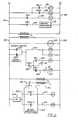
- FIG. 2 there can be seen a partial schematic of a wiring diagram for an air conditioning unit.
- power is supplied through lines L-1 and L-2 to a power portion of the circuit.
- Wires 101 and 102 are shown connecting the various components.
- L-1 is connected to wire 101 which is connected to compressor relay contact CR1-1, compressor relay contacts CR2-2, fan relay contacts FR-1, heating relay contacts HR-1 and one winding of transformer T-1.
- Wire 102 is connected to compressor contactor CC-1, compressor contactor CC-2, fan contactor FC and to heating sequencer 110 and one winding of transformer T-1.
- Wire 104 connects compressor relay contacts CR1-1 to compressor contactor CC-1.
- Wire 105 connects compressor relay contacts CR2-2 to compressor contacts CC-2.
- Wire 106 connects fan relay contacts FR-1 to fan contactor FC.
- Wire 107 connects heating relay contacts HR-1 to heating sequencer 110.
- Wire 201 and 202 connected to the reduced voltage winding of transformer T-1 are wires 201 and 202.
- Wire 201 is additionally connected to clock 225, bypass switch 227, clock contacts 229, transformer T-2 and to low ambient level lockout 230.
- Wire 202 is shown connected to clock 225, time delay relay TDR, fan relay FR, delay relay DR, heating relay HR, transformer T-2, compressor relay CR-1 and compressor relay CR-2.
- Wire 203 connects bypass switch 227 and clock contacts 229 with time delay relay TDR, fan relay FR and time delay contacts TDR-1.
- Wire 204 connects normally open time delay contacts TDR-1 normally open delay relay contacts DR-1 with temperature sensing element 67 and normally closed delay relay contacts DR-2.
- Wire 205 connects normally open delay relay contacts DR-1 with delay relay DR and temperature sensing element 67.
- Wire 206 connects normally closed delay relay contacts DR-2 with temperature sensing element 68.
- Wire 207 connects temperature sensing element 68 with heating relay HR.
- Wire 212 connects microprocessor 220 to a winding of transformer T-2 through normally open delay relay contacts DR-3.
- Wire 210 completes the circuit between transformer T-2 and microprocessor 220.
- Wire 222 connects the low ambient limit lockout 230 with switch Cool 1 and switch Cool 2, each a part of the microprocessor control.
- Wire 224 connects switch Cool 1 with compressor relay CR-1 and wire 226 connects switch Cool 2 with compressor relay CR-2.
- a typical wire schematic would include the compressor contactors CC-1 and CC-2 energizing the three legs of a polyphase motor through various relays.
- the fan contactor would energize the fan motor in a similar manner.
- the heating sequencer would typically provide a series of resistance heating elements which would be energized after various time delays to provide heating input to the indoor air flowing thereover.
- the microprocessor as described above is a commercially available microprocessor control sold to the air conditioning industry by Honeywell, Inc. of Minneapolis, Minnesota.
- a clock 225 is conventionally utilized to recurrently energize an air conditioning system on a planned schedule such as daily for a time interval from 7:00 A.M. to 9:00 P.M.
- the clock will call for energization of the air conditioning unit when the morning time is reached.
- Clock 225 at that time energizes clock contacts 229 supplying energy to the time delay relay TDR and fan relay FR.
- the fan relay energizes, through fan relay contacts FR-1, wire 106 and fan contactor FC, the fan motor driving supply fan 30. Air is then circulated through the supply plenum 60 to the enclosure and from the enclosure through return plenum 61 to the indoor section 19 of the air conditioning unit.
- Sensing elements 67 and 68 correspond to the return plenum thermostat 64 shown in Figure 1.
- temperature sensing element 68 will close energizing through wire 207 heating relay HR.
- Heating relay HR will close normally open heating relay contacts HR-1 which energizes through wire 107 heating sequencer 110 bringing on electric resistance heat.
- temperature sensing element 68 open de-energizing through heating relay HR the electric resistance elements. The temperature sensing element 68 will cycle bringing on the heating element through the heating relay until a cooling need is ascertained.
- variable air volume unit In the heating mode a variable air volume unit may be operated similarly to a constant volume unit.
- the individual discharge terminals may be connected to be opened wide allowing for maximum heated air flow from the terminals in the heating mode.
- temperature element 67 will close energizing through wire 205 delay relay DR. Temperature element 67 may close after an interval during which the fan is operated and without the unit having operated in the heating mode previously. Once temperature element 67 closes delay relay DR is energized which acts to de-energize or open normally closed delay relay contacts DR-2 thereby preventing heating operation through the heating relay and acts to close normally open delay relay contacts DR-1 which acts to lock in the delay relay. Hence, once temperature sensing element 67 has been closed energizing the delay relay the delay relay remains constantly energized thereafter until the unit is de-energized at the end of the daily time period.
- delay relay DR Once delay relay DR is energized the unit operates in the conventional mode of operation and the startup control period is terminated.
- Normally open delay relay contacts DR-3 are closed energizing microprocessor 220 through wires 210, 212 and transformer T-2.
- sequencing of the air conditioning unit in the cooling operation is controlled by microprocessor switches Cool 1 and Cool 2 which sequentially energize compressor relays CR-1 and CR-2 which act to close compressor relay contacts CR1-1 energizing compressor contactor 1 through wire 104 and compressor relay contacts CR2-2 energizing through wire 105 compressor contactor 2.
- the compressor contactors act to energize the compressor motors bringing the refrigeration circuits into operation to effect heat transfer from the indoor air.
- Low ambient lockout switch 230 is used to deactivate the compressor operation if the outdoor ambient temperature drops to a point where operation may affect icing or potential damage to the air conditioning circuits.
- the described circuit and operating method herein allow for a startup period during which operation of the air conditioning unit is controlled by return plenum temperatures regardless of the discharge temperatures. During this time interval heating may be accomplished separate from the discharge air temperature and a period may be allowed in which air is circulated until there is a proven demand. Once the demand is proven the unit is operated in the cooling mode as if it were under normal discharge temperature control.
Description
- A typical air conditioning unit includes a fan for 'circulating air to an enclosure to be conditioned and a refrigeration circuit including a compressor, condenser, evaporator and expansion device for absorbing heat energy from the air. Additionally, heating means in the form of electric resistance heaters, fuel fired burners or a reversible refrigeration system may be incorporated into the air conditioning unit. Other features such as economizer operation for drawing cooler ambient air into the enclosure may also be provided. The operation of the unit is typically controlled by a temperature sensing element located either in the enclosure or in the discharge air stream from the air conditioning unit. Based upon the temperatures sensed, the unit is operated in the heating or cooling mode such that the enclosure temperature is maintained in the appropriate range.
- In a typical commercial application, the air conditioning unit is operated on a weekly schedule such as five days a week in an office building or seven days a week in a store or other application where there is daily use. To save energy, air conditioning is typically operated only during the hours of use and anytime period prior to use for conditioning the air to the appropriate temperature range. In a typical store application an air conditioning unit may be energized at 7:00 A.M. to provide the appropriate enclosure conditions by 9:00 A.M. when the store is opened to the public. The air conditioning unit may then be de-energized at 8:00 P.M. with the store . allowed to coast until the 9:00 P.M. closing time.
- One type of air conditioning system is controlled based on discharge air temperature from the system. Specifically, variable air volume systems are those systems wherein the supply air is ducted to numerous outlets, each of which modulates to vary the volume of air being discharged therefrom in response to the temperature condition of that area. These devices typically include a bladder type device which opens or closes a port allowing a predetermined volume of air to enter that portion of the enclosure. A single temperature sensing element in the enclosure would be ineffective to regulate the air conditioning unit since the total demand is a function of all the individual variable air volume outlets. Hence, in this type application the temperature being sensed is the discharge temperature from the air conditioning unit which is the temperature of the air being supplied to a supply plenum for conducting the air to the various air volume outlets.
- It has been found that upon the recurrent energization of the air conditioning unit on a daily basis typically done on a seven day time clock, there is very little cooling load when the unit is first initiated. In fact, upon initiation there may be a brief heating need to bring the enclosure up to the desired temperature.
- It has additionally been found that upon initiation of the unit in the morning or startup that the temperature sensed in the supply plenum is typically warm although not necessarily indicative of the enclosure requiring cooling. Since this supply plenum temperature is warm the air conditioning unit is operated in the cooling mode until the supply plenum is reduced in temperature. This operation of the unit may be unnecessary and effect cooling of the enclosure below a desired temperature. In use with a variable air volume system this operation may create additional potential problems since the variable air volume outlets will always discharge a minimum amount of conditioned air flow and hence a cool building may be further cooled at startup based on a discharge plenum thermostat.
- Additionally, an occasional heating requirement in a commercial building may be found upon startup. Although the unit senses a heating load it is desirable to have the unit operate only in a heating mode for a brief period to raise the temperature of the enclosure and thereafter to switch to a cooling mode for the remainder of the time interval for which it will operate. In the past, with a variable air volume system it has been possible to operate the unit to supply heat energy which raises the discharge plenum temperature to the point where the unit is then operated in the cooling mode. Hence, the air conditioning unit under these circumstances is operated sequentially in heating and cooling wasting energy and providing little net effect to the enclosure.
- The present control scheme provides a system wherein upon startup of the unit on daily or other recurrent basis a fan is first operated. The fan circulates air for a predetermined time interval, said air flowing from the unit through a supply plenum to the enclosure and through a return plenum back to the unit. A temperature sensor is mounted in the return plenum to determine the temperature of the return air.
- If the temperature of the return air is sufficiently high the unit will enter the cooling mode and then be operated from the discharge temperature sensor. If the temperature of the return air is insufficient to require cooling then the discharge temperature sensor will be bypassed preventing the unit from operating in the cooling mode until the return air temperature rises to a predetermined temperature level.
- If heating is required, the return air sensor will initiate the heating cycle. Once this cycle is complete the thermostat will allow the unit to be operated in the heating mode to satisfy the heating load. Should the return air sensor detect a temperature sufficiently high enough to indicate that cooling is required the heating mode of operation of the air conditioning unit will be locked out for the remainder of that time interval. Hence, the method and apparatus described herein act to prevent needless, redundant or energy wasteful operation of the air conditioning unit during startup at the beginning of each time interval.
- According to the present invention there is provided a method of controlling an air conditioning unit which is recurrently energized to condition an enclosure for a time interval, said air conditioning unit including a fan for circulating air into and through the enclosure, a return air duct for conducting air from the enclosure to the air conditioning unit and a refrigeration circuit for removing heat energy from the air of the enclosure, characterized by the steps of (a) energizing the fan to circulate air from the enclosure to the air conditioning unit, sensing the temperature of the air flowing through the return air duct, and detecting the temperature of the air after it has been circulated in heat exchange relationship with the refrigeration circuit, and either (b) energizing the refrigeration circuit upon an appropriate temperature being ascertained by the step of detecting or (c) preventing the step of energizing until the temperature ascertained by the step of sensing exceeds a predetermined threshold temperature upon startup of the air conditioning unit at the beginning of a time interval.
- According to a further aspect of the invention, there is provided apparatus for proving a need for cooling of an enclosure before allowing an air conditioning unit refrigeration circuit to be energized upon startup of an air conditioning unit which is characterized by initiation means for energizing the air conditioning unit for a time interval during which the air temperature of the enclosure is controlled by the air conditioning unit, a fan for circulating air between the enclosure to be conditioned and the air conditioning unit, a first thermostat for sensing the temperature of the air being circulated from the air conditioning unit to the enclosure, a second thermostat comprising a sensing element for sensing the temperature of the air from the enclosure being circulated to the air conditioning unit, circuit means connected to the first thermostat and a compressor motor of the refrigeration circuit for energizing the refrigeration circuit when a cooling need is sensed by the first thermostat, and lockout means including a delay relay energisable by said temperature sensing element when a threshold temperature is reached having first normally open delay relay contacts connected to at least one of the circuit means, first thermostat or the compressor motor of the refrigeration circuit, said lockout means including switching means connected to the second thermostat for maintaining the first normally open delay relay contacts open to prevent operation of the refrigeration circuit until the temperature sensed by the second thermostat exceeds a predetermined threshold level upon startup of the unit.
- Figure 1 is a schematic view of a rooftop type air conditioning unit mounted to an enclosure.
- Figure 2 is a schematic view of a wiring schematic for controlling an air conditioning unit.
- Referring now to Figure 1 there can be seen a rooftop
air conditioning unit 10 mounted viaroof curb 82 toroof 80 ofenclosure 100.Air conditioning unit 10 includesindoor heat exchanger 42 andoutdoor heat exchanger 40.Compressors condenser fan 20 powered bycondenser fan motor 18 are all shown located inoutdoor section 17 of the air conditioning unit.Indoor section 19 of the air conditioning unit has located thereinindoor heat exchanger 42,fan motor 32 andsupply fan 30. Economizer 50 is mounted tounit 10 and includesdampers 52 which allow ambient air to enter the indoor section of the air conditioning unit. - Under normal operation conditions, heat energy is transferred between outdoor ambient air being circulated through the
outdoor heat exchanger 40 bycondenser fan 20 and theindoor heat exchanger 42 having the enclosure air circulated therethrough bysupply fan 30. Outdoor ambient air may also be drawn into the unit via economizer 50. - Supply plenum 60 is connected to the air conditioning unit to receive the indoor air being discharged by
supply fan 30. -
Discharge plenum thermostat 66 is located to sense the temperature of the air being discharged from the air conditioning unit.Return plenum 61 is shown connected to direct air from the enclosure to the supply fan of the indoor section of the heat exchange unit. Returnplenum thermostat 64 is mounted in the return air flow , stream to sense the temperature of the return air.Enclosure 100 is labeled to define the space to be conditioned which may be a commercial building, store or office building or the like. - Referring now to Figure 2 there can be seen a partial schematic of a wiring diagram for an air conditioning unit. Therein it can be seen that power is supplied through lines L-1 and L-2 to a power portion of the circuit.
Wires wire 101 which is connected to compressor relay contact CR1-1, compressor relay contacts CR2-2, fan relay contacts FR-1, heating relay contacts HR-1 and one winding of transformer T-1. Wire 102 is connected to compressor contactor CC-1, compressor contactor CC-2, fan contactor FC and toheating sequencer 110 and one winding of transformer T-1. Wire 104 connects compressor relay contacts CR1-1 to compressor contactor CC-1. Wire 105 connects compressor relay contacts CR2-2 to compressor contacts CC-2. Wire 106 connects fan relay contacts FR-1 to fan contactor FC. Wire 107 connects heating relay contacts HR-1 toheating sequencer 110. - In the controls portion of the wiring diagram it can be seen that connected to the reduced voltage winding of transformer T-1 are
wires clock 225,bypass switch 227,clock contacts 229, transformer T-2 and to lowambient level lockout 230.Wire 202 is shown connected toclock 225, time delay relay TDR, fan relay FR, delay relay DR, heating relay HR, transformer T-2, compressor relay CR-1 and compressor relay CR-2.Wire 203 connectsbypass switch 227 andclock contacts 229 with time delay relay TDR, fan relay FR and time delay contacts TDR-1.Wire 204 connects normally open time delay contacts TDR-1 normally open delay relay contacts DR-1 withtemperature sensing element 67 and normally closed delay relay contacts DR-2.Wire 205 connects normally open delay relay contacts DR-1 with delay relay DR andtemperature sensing element 67.Wire 206 connects normally closed delay relay contacts DR-2 withtemperature sensing element 68.Wire 207 connectstemperature sensing element 68 with heating relay HR. -
Wire 212 connectsmicroprocessor 220 to a winding of transformer T-2 through normally open delay relay contacts DR-3.Wire 210 completes the circuit between transformer T-2 andmicroprocessor 220.Wire 222 connects the lowambient limit lockout 230 withswitch Cool 1 and switchCool 2, each a part of the microprocessor control.Wire 224 connectsswitch Cool 1 with compressor relay CR-1 and wire 226 connectsswitch Cool 2 with compressor relay CR-2. - Numerous other details of the wiring schematic for this type of air conditioning unit have been omitted for the sake of clarity. Although the compressor contactors CC-1 and CC-2 and fan contactor FC and the heating sequencer have been shown in the power portion of Figure 2, the specific motors and heating elements have not been shown. A typical wire schematic would include the compressor contactors CC-1 and CC-2 energizing the three legs of a polyphase motor through various relays. The fan contactor would energize the fan motor in a similar manner. The heating sequencer would typically provide a series of resistance heating elements which would be energized after various time delays to provide heating input to the indoor air flowing thereover. The microprocessor as described above is a commercially available microprocessor control sold to the air conditioning industry by Honeywell, Inc. of Minneapolis, Minnesota.
- A
clock 225 is conventionally utilized to recurrently energize an air conditioning system on a planned schedule such as daily for a time interval from 7:00 A.M. to 9:00 P.M. The clock will call for energization of the air conditioning unit when the morning time is reached.Clock 225 at that time energizesclock contacts 229 supplying energy to the time delay relay TDR and fan relay FR. The fan relay energizes, through fan relay contacts FR-1, wire 106 and fan contactor FC, the fan motor drivingsupply fan 30. Air is then circulated through the supply plenum 60 to the enclosure and from the enclosure throughreturn plenum 61 to theindoor section 19 of the air conditioning unit. After a predetermined time interval has elapsed time delay relay TDR closes time delay relay contacts TDR-1 thereby supplying power to normally open delay relay contacts DR-1, to sensingelement 67 and to sensingelement 68 through normally closed delay relay contacts DR-2.Sensing elements return plenum thermostat 64 shown in Figure 1. When the temperature being sensed bytemperature sensing elements temperature sensing element 68 will close energizing throughwire 207 heating relay HR. Heating relay HR will close normally open heating relay contacts HR-1 which energizes throughwire 107heating sequencer 110 bringing on electric resistance heat. Once the heating load is satisfiedtemperature sensing element 68 open de-energizing through heating relay HR the electric resistance elements. Thetemperature sensing element 68 will cycle bringing on the heating element through the heating relay until a cooling need is ascertained. - In the heating mode a variable air volume unit may be operated similarly to a constant volume unit. The individual discharge terminals may be connected to be opened wide allowing for maximum heated air flow from the terminals in the heating mode.
- Should
temperature element 67 indicate a sufficiently high temperture to prove there is a cooling need,temperature element 67 will close energizing throughwire 205 delay relay DR.Temperature element 67 may close after an interval during which the fan is operated and without the unit having operated in the heating mode previously. Oncetemperature element 67 closes delay relay DR is energized which acts to de-energize or open normally closed delay relay contacts DR-2 thereby preventing heating operation through the heating relay and acts to close normally open delay relay contacts DR-1 which acts to lock in the delay relay. Hence, oncetemperature sensing element 67 has been closed energizing the delay relay the delay relay remains constantly energized thereafter until the unit is de-energized at the end of the daily time period. - Once delay relay DR is energized the unit operates in the conventional mode of operation and the startup control period is terminated. Normally open delay relay contacts DR-3 are closed energizing
microprocessor 220 throughwires microprocessor switches Cool 1 andCool 2 which sequentially energize compressor relays CR-1 and CR-2 which act to close compressor relay contacts CR1-1 energizingcompressor contactor 1 throughwire 104 and compressor relay contacts CR2-2 energizing throughwire 105compressor contactor 2. The compressor contactors act to energize the compressor motors bringing the refrigeration circuits into operation to effect heat transfer from the indoor air. Lowambient lockout switch 230 is used to deactivate the compressor operation if the outdoor ambient temperature drops to a point where operation may affect icing or potential damage to the air conditioning circuits. - The described circuit and operating method herein allow for a startup period during which operation of the air conditioning unit is controlled by return plenum temperatures regardless of the discharge temperatures. During this time interval heating may be accomplished separate from the discharge air temperature and a period may be allowed in which air is circulated until there is a proven demand. Once the demand is proven the unit is operated in the cooling mode as if it were under normal discharge temperature control.
Claims (7)
Applications Claiming Priority (2)
| Application Number | Priority Date | Filing Date | Title |
|---|---|---|---|
| US293056 | 1981-08-17 | ||
| US06/293,056 US4399862A (en) | 1981-08-17 | 1981-08-17 | Method and apparatus for proven demand air conditioning control |
Publications (2)
| Publication Number | Publication Date |
|---|---|
| EP0072442A1 EP0072442A1 (en) | 1983-02-23 |
| EP0072442B1 true EP0072442B1 (en) | 1986-02-26 |
Family
ID=23127464
Family Applications (1)
| Application Number | Title | Priority Date | Filing Date |
|---|---|---|---|
| EP82106427A Expired EP0072442B1 (en) | 1981-08-17 | 1982-07-16 | Method and apparatus for proven demand air conditioning control |
Country Status (5)
| Country | Link |
|---|---|
| US (1) | US4399862A (en) |
| EP (1) | EP0072442B1 (en) |
| JP (2) | JPS5837443A (en) |
| DE (1) | DE3269372D1 (en) |
| ZA (1) | ZA825063B (en) |
Families Citing this family (25)
| Publication number | Priority date | Publication date | Assignee | Title |
|---|---|---|---|---|
| EP0228813B1 (en) | 1985-11-27 | 1993-06-02 | Nippondenso Co., Ltd. | Air conditioner for automobiles |
| US4817864A (en) * | 1986-08-28 | 1989-04-04 | Honeywell Inc. | Temperature compensation for vav system |
| IT1228397B (en) * | 1989-01-26 | 1991-06-14 | Il Consiglio Nazionale Delle R | PREFABRICATED SYSTEM FOR AIR CONDITIONING OF BUILDINGS. |
| US5077983A (en) * | 1990-11-30 | 1992-01-07 | Electric Power Research Institute, Inc. | Method and apparatus for improving efficiency of a pulsed expansion valve heat pump |
| US6298912B1 (en) | 1999-06-22 | 2001-10-09 | York International Corporation | Method and system for controlling an economizer |
| WO2010039691A2 (en) * | 2008-09-30 | 2010-04-08 | Carrier Corporation | Control of a conditioned air supply system |
| EP2577178B1 (en) | 2010-05-25 | 2019-07-24 | 7AC Technologies, Inc. | Methods and systems using liquid desiccants for air-conditioning and other processes |
| KR101216085B1 (en) * | 2010-08-17 | 2012-12-26 | 엘지전자 주식회사 | Heat pump |
| US9683748B2 (en) * | 2011-03-11 | 2017-06-20 | Carrier Corporation | Rooftop hydronic heating unit |
| WO2013188388A2 (en) | 2012-06-11 | 2013-12-19 | 7Ac Technologies, Inc. | Methods and systems for turbulent, corrosion resistant heat exchangers |
| US9506697B2 (en) | 2012-12-04 | 2016-11-29 | 7Ac Technologies, Inc. | Methods and systems for cooling buildings with large heat loads using desiccant chillers |
| US9435557B2 (en) | 2013-01-24 | 2016-09-06 | Belimo Holding Ag | Control unit for an HVAC system comprising an economizer and method for operating such control unit |
| KR20150122167A (en) | 2013-03-01 | 2015-10-30 | 7에이씨 테크놀로지스, 아이엔씨. | Desiccant air conditioning methods and systems |
| US9651268B2 (en) * | 2013-03-11 | 2017-05-16 | Rheem Manufacturing Company | Gas fired modular blower control and associated methodology |
| US20140260399A1 (en) | 2013-03-14 | 2014-09-18 | 7Ac Technologies, Inc. | Methods and systems for mini-split liquid desiccant air conditioning |
| JP6395801B2 (en) * | 2013-03-14 | 2018-09-26 | 7エーシー テクノロジーズ,インコーポレイテッド | Method and system for retrofitting liquid desiccant air conditioning system |
| ES2759926T3 (en) | 2013-06-12 | 2020-05-12 | 7Ac Tech Inc | Liquid Desiccant Air Conditioning System |
| KR102641608B1 (en) | 2014-03-20 | 2024-02-28 | 코프랜드 엘피 | Rooftop liquid desiccant systems and methods |
| US20150354867A1 (en) * | 2014-06-06 | 2015-12-10 | Enthaltec, Inc. | Hvac roof curb retrofit |
| US10024558B2 (en) | 2014-11-21 | 2018-07-17 | 7Ac Technologies, Inc. | Methods and systems for mini-split liquid desiccant air conditioning |
| US11274861B2 (en) * | 2016-10-10 | 2022-03-15 | Johnson Controls Technology Company | Method and apparatus for isolating heat exchanger from the air handling unit in a single-packace outdoor unit |
| CN106765940B (en) * | 2016-12-16 | 2019-10-11 | 奥克斯空调股份有限公司 | The control method of solar heat protection outlet air when a kind of air conditioner freezes |
| US10941948B2 (en) | 2017-11-01 | 2021-03-09 | 7Ac Technologies, Inc. | Tank system for liquid desiccant air conditioning system |
| CN111373202B (en) | 2017-11-01 | 2021-11-26 | 艾默生环境优化技术有限公司 | Method and apparatus for uniform distribution of liquid desiccant in membrane modules in liquid desiccant air conditioning systems |
| US11022330B2 (en) | 2018-05-18 | 2021-06-01 | Emerson Climate Technologies, Inc. | Three-way heat exchangers for liquid desiccant air-conditioning systems and methods of manufacture |
Family Cites Families (11)
| Publication number | Priority date | Publication date | Assignee | Title |
|---|---|---|---|---|
| US2130327A (en) * | 1932-12-24 | 1938-09-13 | Baldwin Southwark Corp | Air conditioning apparatus |
| US2168157A (en) * | 1937-12-23 | 1939-08-01 | Gen Electric | Fluid cooling system |
| JPS5715293B2 (en) * | 1973-05-23 | 1982-03-30 | ||
| US4094166A (en) * | 1977-03-23 | 1978-06-13 | Electro-Thermal Corporation | Air conditioning control system |
| JPS5478850A (en) * | 1977-12-07 | 1979-06-23 | Hitachi Ltd | Temperature control circuit for air conditioner |
| US4254633A (en) * | 1978-04-20 | 1981-03-10 | Matsushita Electric Industrial Co., Ltd. | Control apparatus for an air conditioner |
| JPS5938495B2 (en) * | 1978-05-23 | 1984-09-17 | 三洋電機株式会社 | Automatic operation control method for heat pump air conditioner |
| JPS5528999U (en) * | 1978-08-17 | 1980-02-25 | ||
| US4237966A (en) * | 1979-01-24 | 1980-12-09 | Tomlinson Joe W | Energy conserving heating and air conditioning system |
| US4242876A (en) * | 1979-03-27 | 1981-01-06 | Carrier Corporation | Rooftop type air conditioner |
| GB2060215B (en) * | 1979-09-26 | 1983-05-25 | Eaton Williams Group Ltd | Automatic control of temperature |
-
1981
- 1981-08-17 US US06/293,056 patent/US4399862A/en not_active Expired - Fee Related
-
1982
- 1982-07-15 ZA ZA825063A patent/ZA825063B/en unknown
- 1982-07-16 EP EP82106427A patent/EP0072442B1/en not_active Expired
- 1982-07-16 DE DE8282106427T patent/DE3269372D1/en not_active Expired
- 1982-08-17 JP JP57142579A patent/JPS5837443A/en active Pending
-
1989
- 1989-12-26 JP JP1989149998U patent/JPH0293641U/ja active Pending
Also Published As
| Publication number | Publication date |
|---|---|
| DE3269372D1 (en) | 1986-04-03 |
| ZA825063B (en) | 1983-08-31 |
| JPH0293641U (en) | 1990-07-25 |
| JPS5837443A (en) | 1983-03-04 |
| EP0072442A1 (en) | 1983-02-23 |
| US4399862A (en) | 1983-08-23 |
Similar Documents
| Publication | Publication Date | Title |
|---|---|---|
| EP0072442B1 (en) | Method and apparatus for proven demand air conditioning control | |
| US4178988A (en) | Control for a combination furnace and heat pump system | |
| EP0072982B1 (en) | A method and apparatus for controlling an air conditioning unit with multi-speed fan and economizer | |
| US4094166A (en) | Air conditioning control system | |
| US4193781A (en) | Head pressure control for heat reclaim refrigeration systems | |
| US4228846A (en) | Control apparatus for a two-speed heat pump | |
| US4550770A (en) | Reverse cycle room air conditioner with auxilliary heat actuated at low and high outdoor temperatures | |
| US4105064A (en) | Two stage compressor heating | |
| US5701750A (en) | Zone demand controlled dual heat pump system and controller therefor | |
| US5488218A (en) | Electric heat control apparatus and method | |
| EP0498645B1 (en) | A control apparatus for an air conditioner | |
| US4102391A (en) | Heat pump frost control system | |
| US4102390A (en) | Control system for heat pump and furnace combination | |
| US4373350A (en) | Heat pump control/defrost circuit | |
| US4246956A (en) | Control scheme for a solar assisted heat pump | |
| EP0330157A2 (en) | Air conditioning system with periodic fan operation | |
| GB2060216A (en) | Heat pump control system | |
| EP0007497A1 (en) | Air conditioning system and method for heating and cooling an enclosure | |
| EP0080838B1 (en) | Air conditioning economizer control method and apparatus | |
| US4703795A (en) | Control system to delay the operation of a refrigeration heat pump apparatus after the operation of a furnace is terminated | |
| US3318372A (en) | Emergency control system for a heat pump and method | |
| US6176306B1 (en) | Method and device for controlling operation of heat pump | |
| US3324672A (en) | Electrically controlled conditioning system | |
| US4024722A (en) | Heat pump frost control system | |
| US4271899A (en) | Heat pump control system |
Legal Events
| Date | Code | Title | Description |
|---|---|---|---|
| PUAI | Public reference made under article 153(3) epc to a published international application that has entered the european phase |
Free format text: ORIGINAL CODE: 0009012 |
|
| AK | Designated contracting states |
Designated state(s): BE DE FR IT |
|
| 17P | Request for examination filed |
Effective date: 19830620 |
|
| GRAA | (expected) grant |
Free format text: ORIGINAL CODE: 0009210 |
|
| AK | Designated contracting states |
Designated state(s): BE DE FR IT |
|
| ITF | It: translation for a ep patent filed |
Owner name: ING. C. GREGORJ S.P.A. |
|
| REF | Corresponds to: |
Ref document number: 3269372 Country of ref document: DE Date of ref document: 19860403 |
|
| ET | Fr: translation filed | ||
| PLBE | No opposition filed within time limit |
Free format text: ORIGINAL CODE: 0009261 |
|
| STAA | Information on the status of an ep patent application or granted ep patent |
Free format text: STATUS: NO OPPOSITION FILED WITHIN TIME LIMIT |
|
| 26N | No opposition filed | ||
| ITTA | It: last paid annual fee | ||
| PGFP | Annual fee paid to national office [announced via postgrant information from national office to epo] |
Ref country code: DE Payment date: 19940708 Year of fee payment: 13 |
|
| PGFP | Annual fee paid to national office [announced via postgrant information from national office to epo] |
Ref country code: FR Payment date: 19940711 Year of fee payment: 13 |
|
| PGFP | Annual fee paid to national office [announced via postgrant information from national office to epo] |
Ref country code: BE Payment date: 19940912 Year of fee payment: 13 |
|
| PG25 | Lapsed in a contracting state [announced via postgrant information from national office to epo] |
Ref country code: BE Effective date: 19950731 |
|
| BERE | Be: lapsed |
Owner name: CARRIER CORP. Effective date: 19950731 |
|
| PG25 | Lapsed in a contracting state [announced via postgrant information from national office to epo] |
Ref country code: DE Effective date: 19960402 |
|
| PG25 | Lapsed in a contracting state [announced via postgrant information from national office to epo] |
Ref country code: FR Effective date: 19960430 |
|
| REG | Reference to a national code |
Ref country code: FR Ref legal event code: ST |
|
| REG | Reference to a national code |
Ref country code: FR Ref legal event code: ST |
|
| REG | Reference to a national code |
Ref country code: FR Ref legal event code: ST |