EP0074263A2 - Graphite fiber reinforced laminate structure capable of withstanding lightning strikes - Google Patents
Graphite fiber reinforced laminate structure capable of withstanding lightning strikes Download PDFInfo
- Publication number
- EP0074263A2 EP0074263A2 EP19820304661 EP82304661A EP0074263A2 EP 0074263 A2 EP0074263 A2 EP 0074263A2 EP 19820304661 EP19820304661 EP 19820304661 EP 82304661 A EP82304661 A EP 82304661A EP 0074263 A2 EP0074263 A2 EP 0074263A2
- Authority
- EP
- European Patent Office
- Prior art keywords
- laminate structure
- graphite
- ply
- laminate
- wire
- Prior art date
- Legal status (The legal status is an assumption and is not a legal conclusion. Google has not performed a legal analysis and makes no representation as to the accuracy of the status listed.)
- Withdrawn
Links
Images

Classifications
-
- B—PERFORMING OPERATIONS; TRANSPORTING
- B29—WORKING OF PLASTICS; WORKING OF SUBSTANCES IN A PLASTIC STATE IN GENERAL
- B29C—SHAPING OR JOINING OF PLASTICS; SHAPING OF MATERIAL IN A PLASTIC STATE, NOT OTHERWISE PROVIDED FOR; AFTER-TREATMENT OF THE SHAPED PRODUCTS, e.g. REPAIRING
- B29C70/00—Shaping composites, i.e. plastics material comprising reinforcements, fillers or preformed parts, e.g. inserts
- B29C70/04—Shaping composites, i.e. plastics material comprising reinforcements, fillers or preformed parts, e.g. inserts comprising reinforcements only, e.g. self-reinforcing plastics
- B29C70/06—Fibrous reinforcements only
- B29C70/10—Fibrous reinforcements only characterised by the structure of fibrous reinforcements, e.g. hollow fibres
- B29C70/16—Fibrous reinforcements only characterised by the structure of fibrous reinforcements, e.g. hollow fibres using fibres of substantial or continuous length
- B29C70/22—Fibrous reinforcements only characterised by the structure of fibrous reinforcements, e.g. hollow fibres using fibres of substantial or continuous length oriented in at least two directions forming a two dimensional structure
-
- B—PERFORMING OPERATIONS; TRANSPORTING
- B29—WORKING OF PLASTICS; WORKING OF SUBSTANCES IN A PLASTIC STATE IN GENERAL
- B29C—SHAPING OR JOINING OF PLASTICS; SHAPING OF MATERIAL IN A PLASTIC STATE, NOT OTHERWISE PROVIDED FOR; AFTER-TREATMENT OF THE SHAPED PRODUCTS, e.g. REPAIRING
- B29C70/00—Shaping composites, i.e. plastics material comprising reinforcements, fillers or preformed parts, e.g. inserts
- B29C70/04—Shaping composites, i.e. plastics material comprising reinforcements, fillers or preformed parts, e.g. inserts comprising reinforcements only, e.g. self-reinforcing plastics
- B29C70/06—Fibrous reinforcements only
- B29C70/08—Fibrous reinforcements only comprising combinations of different forms of fibrous reinforcements incorporated in matrix material, forming one or more layers, and with or without non-reinforced layers
-
- B—PERFORMING OPERATIONS; TRANSPORTING
- B29—WORKING OF PLASTICS; WORKING OF SUBSTANCES IN A PLASTIC STATE IN GENERAL
- B29C—SHAPING OR JOINING OF PLASTICS; SHAPING OF MATERIAL IN A PLASTIC STATE, NOT OTHERWISE PROVIDED FOR; AFTER-TREATMENT OF THE SHAPED PRODUCTS, e.g. REPAIRING
- B29C70/00—Shaping composites, i.e. plastics material comprising reinforcements, fillers or preformed parts, e.g. inserts
- B29C70/88—Shaping composites, i.e. plastics material comprising reinforcements, fillers or preformed parts, e.g. inserts characterised primarily by possessing specific properties, e.g. electrically conductive or locally reinforced
- B29C70/882—Shaping composites, i.e. plastics material comprising reinforcements, fillers or preformed parts, e.g. inserts characterised primarily by possessing specific properties, e.g. electrically conductive or locally reinforced partly or totally electrically conductive, e.g. for EMI shielding
- B29C70/885—Shaping composites, i.e. plastics material comprising reinforcements, fillers or preformed parts, e.g. inserts characterised primarily by possessing specific properties, e.g. electrically conductive or locally reinforced partly or totally electrically conductive, e.g. for EMI shielding with incorporated metallic wires, nets, films or plates
-
- B—PERFORMING OPERATIONS; TRANSPORTING
- B32—LAYERED PRODUCTS
- B32B—LAYERED PRODUCTS, i.e. PRODUCTS BUILT-UP OF STRATA OF FLAT OR NON-FLAT, e.g. CELLULAR OR HONEYCOMB, FORM
- B32B17/00—Layered products essentially comprising sheet glass, or glass, slag, or like fibres
- B32B17/02—Layered products essentially comprising sheet glass, or glass, slag, or like fibres in the form of fibres or filaments
-
- B—PERFORMING OPERATIONS; TRANSPORTING
- B64—AIRCRAFT; AVIATION; COSMONAUTICS
- B64D—EQUIPMENT FOR FITTING IN OR TO AIRCRAFT; FLIGHT SUITS; PARACHUTES; ARRANGEMENTS OR MOUNTING OF POWER PLANTS OR PROPULSION TRANSMISSIONS IN AIRCRAFT
- B64D45/00—Aircraft indicators or protectors not otherwise provided for
- B64D45/02—Lightning protectors; Static dischargers
-
- D—TEXTILES; PAPER
- D03—WEAVING
- D03D—WOVEN FABRICS; METHODS OF WEAVING; LOOMS
- D03D15/00—Woven fabrics characterised by the material, structure or properties of the fibres, filaments, yarns, threads or other warp or weft elements used
- D03D15/60—Woven fabrics characterised by the material, structure or properties of the fibres, filaments, yarns, threads or other warp or weft elements used characterised by the warp or weft elements other than yarns or threads
- D03D15/67—Metal wires
-
- B—PERFORMING OPERATIONS; TRANSPORTING
- B29—WORKING OF PLASTICS; WORKING OF SUBSTANCES IN A PLASTIC STATE IN GENERAL
- B29K—INDEXING SCHEME ASSOCIATED WITH SUBCLASSES B29B, B29C OR B29D, RELATING TO MOULDING MATERIALS OR TO MATERIALS FOR MOULDS, REINFORCEMENTS, FILLERS OR PREFORMED PARTS, e.g. INSERTS
- B29K2705/00—Use of metals, their alloys or their compounds, for preformed parts, e.g. for inserts
-
- B—PERFORMING OPERATIONS; TRANSPORTING
- B29—WORKING OF PLASTICS; WORKING OF SUBSTANCES IN A PLASTIC STATE IN GENERAL
- B29K—INDEXING SCHEME ASSOCIATED WITH SUBCLASSES B29B, B29C OR B29D, RELATING TO MOULDING MATERIALS OR TO MATERIALS FOR MOULDS, REINFORCEMENTS, FILLERS OR PREFORMED PARTS, e.g. INSERTS
- B29K2707/00—Use of elements other than metals for preformed parts, e.g. for inserts
- B29K2707/04—Carbon
-
- B—PERFORMING OPERATIONS; TRANSPORTING
- B29—WORKING OF PLASTICS; WORKING OF SUBSTANCES IN A PLASTIC STATE IN GENERAL
- B29K—INDEXING SCHEME ASSOCIATED WITH SUBCLASSES B29B, B29C OR B29D, RELATING TO MOULDING MATERIALS OR TO MATERIALS FOR MOULDS, REINFORCEMENTS, FILLERS OR PREFORMED PARTS, e.g. INSERTS
- B29K2995/00—Properties of moulding materials, reinforcements, fillers, preformed parts or moulds
- B29K2995/0003—Properties of moulding materials, reinforcements, fillers, preformed parts or moulds having particular electrical or magnetic properties, e.g. piezoelectric
- B29K2995/0005—Conductive
-
- Y—GENERAL TAGGING OF NEW TECHNOLOGICAL DEVELOPMENTS; GENERAL TAGGING OF CROSS-SECTIONAL TECHNOLOGIES SPANNING OVER SEVERAL SECTIONS OF THE IPC; TECHNICAL SUBJECTS COVERED BY FORMER USPC CROSS-REFERENCE ART COLLECTIONS [XRACs] AND DIGESTS
- Y10—TECHNICAL SUBJECTS COVERED BY FORMER USPC
- Y10S—TECHNICAL SUBJECTS COVERED BY FORMER USPC CROSS-REFERENCE ART COLLECTIONS [XRACs] AND DIGESTS
- Y10S428/00—Stock material or miscellaneous articles
- Y10S428/902—High modulus filament or fiber
-
- Y—GENERAL TAGGING OF NEW TECHNOLOGICAL DEVELOPMENTS; GENERAL TAGGING OF CROSS-SECTIONAL TECHNOLOGIES SPANNING OVER SEVERAL SECTIONS OF THE IPC; TECHNICAL SUBJECTS COVERED BY FORMER USPC CROSS-REFERENCE ART COLLECTIONS [XRACs] AND DIGESTS
- Y10—TECHNICAL SUBJECTS COVERED BY FORMER USPC
- Y10S—TECHNICAL SUBJECTS COVERED BY FORMER USPC CROSS-REFERENCE ART COLLECTIONS [XRACs] AND DIGESTS
- Y10S428/00—Stock material or miscellaneous articles
- Y10S428/922—Static electricity metal bleed-off metallic stock
-
- Y—GENERAL TAGGING OF NEW TECHNOLOGICAL DEVELOPMENTS; GENERAL TAGGING OF CROSS-SECTIONAL TECHNOLOGIES SPANNING OVER SEVERAL SECTIONS OF THE IPC; TECHNICAL SUBJECTS COVERED BY FORMER USPC CROSS-REFERENCE ART COLLECTIONS [XRACs] AND DIGESTS
- Y10—TECHNICAL SUBJECTS COVERED BY FORMER USPC
- Y10T—TECHNICAL SUBJECTS COVERED BY FORMER US CLASSIFICATION
- Y10T428/00—Stock material or miscellaneous articles
- Y10T428/30—Self-sustaining carbon mass or layer with impregnant or other layer
-
- Y—GENERAL TAGGING OF NEW TECHNOLOGICAL DEVELOPMENTS; GENERAL TAGGING OF CROSS-SECTIONAL TECHNOLOGIES SPANNING OVER SEVERAL SECTIONS OF THE IPC; TECHNICAL SUBJECTS COVERED BY FORMER USPC CROSS-REFERENCE ART COLLECTIONS [XRACs] AND DIGESTS
- Y10—TECHNICAL SUBJECTS COVERED BY FORMER USPC
- Y10T—TECHNICAL SUBJECTS COVERED BY FORMER US CLASSIFICATION
- Y10T442/00—Fabric [woven, knitted, or nonwoven textile or cloth, etc.]
- Y10T442/30—Woven fabric [i.e., woven strand or strip material]
- Y10T442/3382—Including a free metal or alloy constituent
- Y10T442/339—Metal or metal-coated strand
Definitions
- Woven wire mesh has also been found to be difficult to lay up on multiple contoured surfaces. Also, the addition of either the aluminized glass cloth or woven wire mesh would add a significant amount of weight to the laminate structures, which is highly undesirable, especially in the case of an airplane or other aerospace vehicle, where the lighter weight of the graphite composite is an exceptionally desirable attribute and one which contributes to improved fuel consumption.
- Graphite reinforced bonded laminates are protected from the effects of lightning by the present invention in which metal wire or metal coated filament is woven in at least the outer ply of the graphite reinforced laminate structure to increase the. capability of the laminate to withstand lightning strike currents without significant damage.
- the metal wires or filaments do not significantly degrade the mechanical properties of the graphite fibers or the graphite reinforced laminate composite and are woven bidirectionally among the graphite fibers, that is, in both the warp and fill directions.
- the diameter of the wire will be generally in the range of approximately 0.5 mils to about 20 mils and, in a preferred embodiment is in the range of approximately 1 mil to about 10.mils.
- the wires are positioned within the ply such that there is at least 1 wire per 6 tows of the graphite fibers in a ply which has 24 tows per inch.
- the laminate structure of the present invention designated generally by the numeral 1
- the wire or filament has a diameter generally within the range of approximately 0.5 mil to approximately 20 mils and is spaced within the ply such that there is at least 1 wire per 6 tows of graphite fibers in a ply which has 24 tows per inch.
- a preferred embodiment For protection of graphite laminates in lightning strike zone lA (with an intensity of 200 kiloampers at an action integral of 2 X 10 6 ampere 2- seconds as set forth in Society of Automotive Engineers Report, "Lightning Tests-Waveforms and Techniques for Aerospace Vehicles and Hardware” dated June 20,, 1978, and U.S. MIL STD 1757), a preferred embodiment has one 4 mil wire in every third tow in a ply with 24 tows per inch.
- wire sizes and spacings may be appropriate, as for example, when a laminate structure containing only one or two graphite reinforced bonded plies is to be utilized and puncture cannot be tolerated.
- an arrangement of one or more metal wires or filaments.in each tow, or larger diameter wires may be used.
- the metal wire or metal coated filament is of a material which is compatible with the bonded graphite fibers and preferably is aluminum, which has been found to produce extremely satisfactory results.
- aluminum wire may also be tin, -titanium, brass, gold, silver, platinum, copper, nickel, nickel-stainless steel alloys, stainless steel, or other metal or metal alloy possessing the requisite compatibility, as explained more fully below.
- the wire may also be a non-metallic fiber such as graphite, fiberglass or Kevlar (a trademark of E. I. duPont de Nemours & Co. for organic fibers) coated with one of the aforementioned metals.
- the major criteria applied in selecting the appropriate metal wire or filament are that it have sufficient electrical conductivity to enable a portion of the lightning current to be conducted away from the lightning attachment point(s), thereby reducing the energy deposited in the laminate at the strike attachment points; that it present a sufficient electric field intensification at the surface of the laminate to promote multiple lightning attachment points; that it be galvanically compatible with the surrounding graphite or capable of being made so as for example by coating aluminum wire with tin or other appro- riate metal; and that it be sufficiently light to enable the laminate composite to retain this essential characteristic.
- the number of plies comprising the composite laminate structure may vary considerably, depending upon the intended use of the composite and will be governed in large part by the necessary weight and overall strength that are required. Where the laminate structure is to be used for the fuselage or the wings of an airplane, for example, multiple plies will usually be utilized. In such a case, to provide the necessary protection against the damaging effects of lightning strikes, at least the exterior surface of the laminate structure will have the described woven metal containing wire, and in cases where additional protective insurance is desired, the next inner ply (numeral 3 in Figure 1) may also have the woven metal containing wire.
- the arrangement of metal wires or filaments interwoven in both the warp and fill directions enables currents entering the laminate (depicted by numeral 10) at any point(s) to spread in all directions (depicted by numerals 11 and 12. It is not necessary for the wires to conduct all of the lightning current, but only a portion of it, so that the portion of lightning current which remains in the graphite is reduced and the amount of energy deposited in the graphite is reduced, thereby reducing the amount of thermal damage. In addition to this mechanism, two other mechanisms contribute to the protection effectiveness of the interwoven wires where the wires or filaments overlap.
- the interwoven wires are adjacent at least the outside surface of the outer ply at periodic intervals at the places of interweaving or overlapping; the interwoven wires may also be adjacent both the upper and lower surfaces of the ply, depending upon the thickness of the resin bonding, and in either case will facilitate conduction of electric currents from the ply, as will now be explained.
- the electric field is intensified locally where the wires are adjacent to the surface of the laminate and dielectric breakdown of the resin and paint occurs and ionized streamers propagate outward to intercept the lightning channel. This is the same effect that causes lightning strikes to seek out the edges of flush rivets beneath paint on metal aircraft skins.
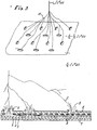
- the interwoven wires thus not only lower the density of lightning current in the graphite but at the same time serve to split the lightning arc into a plurality of filaments as shown in Figure 3.
- the corresponding division of the current into separate current filaments 15 results in a decrease of the action integral associated-with each filament by a factor of 1/n 2 as follows: so that (a) the damaging effect at each filament attachment spot is much lower than it would be in the case where all current enters the laminate at one spot, and (b) the sum of the action integrals associated with all n current filaments is 1/n times that of the total current if conducted in a single arc. If the current can be split up, its damaging effects would therefore be greatly reduced.
- An additional advantage of providing interwoven wires in the outer ply of a multiple ply laminate is that a greater percentage of the lightning current is encouraged to flow in the outer ply and a correspondingly lower percentage enters the inner plies, thereby reducing the damage to the inner plies.
- a graphite fiber cloth such as-that available from Fiberite Corporation under the trade designation W-133, into which the wire or metal filaments have been interwoven, is impregnated with a suitable organic resin which is not in a fully polymerized or cured state. Subsequently, the resin is cured under exposure to heat and in some instances high pressure.
- Epoxy based resins are typically utilized in conjunction with graphite fibers (although other resins may also be used), and final polymerization or curing is conducted at about 250-350 °F for approximately 1/2 to about 3 hours. The exact parameters of the aforementioned curing are, of course, dependent on the chemical properties of the resinous binding material and will be known or readily ascertainable by those skilled in the art.
- Specimens containing three different wire spacings of interwoven aluminum wire and one interwoven brass wire material were prepared.
- the specimens were 12 inch by 12 inch, 4 plies thick.
- the lay up configuration was + 45°, 0° - 90°, 90° - 0°, + 45° and the outer ply contained the interwoven wire.
- the panels were tested and the results are shown in Table I which follows.
- the wire diameter for all specimens was 4 mils.
- Each of the painted specimens were painted with one coat of primer and two coats of enamel prior to testing. In all of the tests, current was delivered to the specimen from an electrode suspended 1 inch above the center and current was removed from the top and bottom of all four edges of the specimens via clamped aluminum bars on two opposite edges and aluminum foil taped on the other two edges.
- specimen No. 5 a painted 4-ply laminate with aluminum wires interwoven in its outer ply and spaced 1/4" apart in both the warp and fill directions, withstood the full design current of 200 kA and action integral of 2 X 10 6 A 2- S without puncture.
- the interwoven wires also lowered the overall laminate resistivity by about 40%.
- a twelve inch square specimen with interwoven wires spaced 1/4" apart had a resistance between opposite edges of 28.1 milliohms, whereas a similar specimen without wires had a resistance of 49 milliohms.
- wire or metal filament is woven only unidirectionally, the desired results are not achieved.
- a 4 mil diameter aluminum wire was woven unidirectionally in Fiberite Corporation style W-133 graphite fabric.
- the spacing of the wire was 0.25 inch.
- This material was used in fabrication of a 12 inch by 12 inch, 3 ply test panel.
- the layup configuration was 0° - 90°, + 45°, 0° - 9- ⁇ ° and the outer 0° - 90° ply contained the interwoven wire.
- the panel was subjected to nearly the full magnitude of component.A (1.57 X 10 6 A 2- S , 192 kA). The test caused severe delamination but was not punctured.
- test panel was not painted and had shown slight improvement over previously tested unpainted graphite panels. Previous testing had demonstrated that painted panels are damaged much more severely than unpainted panels when subjected to the same test conditions. It was concluded that, if the test panel containing interwoven wire were painted, the panel would have been penetrated and the damage would be unacceptable. Additionally, due to the slight amount of damage that lightning strikes may inflict upon laminates protected by this invention, major repairs. will not be required and in many cases only a simple touch-up will be necessary.
Abstract
Description
- It is now well known that graphite reinforced composite materials are susceptible to puncture or other severe damage from lightning strikes. This is because the density of the lightning current injected into the graphite fibers at the point of attachment of the lightning arc is high enough to raise the temperature of the graphite fibers well above the vaporization temperature of the resin matrix. This in turn results in explosive pyrolysis of the resin, pressure buildup, and the destruction of several plies of the composite laminate. Moreover, if the laminate is painted, as is ordinarily the case, it has been found that the paint will tend to concentrate the lightning current at a single point, rather than allow it to divide and enter the laminate at several places, and that it will contain the thermal and blast presure effects of the lightning strike, thus enabling them to build up to 'a greater magnitude. Both of these effects, of course, increase the amount of physical damage to the laminate.
- In addition to the physical damage, the higher resistivity of graphite composites, a resistivity approximately five hundred times greater than that of aluminum, for example, results in excessive structural voltage rises during lightning strike flow. Such structural voltage increases may cause damage to the electrical and avionics equipment contained within an airplane, for example, as well as electrical sparking within the fuel tank.
- In light of the foregoing, it is clear that it is necessary to minimize the physical damage effects of lightning strikes on graphite composites and to reduce the electrical resistance of such composites. In an attempt to achieve this, a flame or arc-sprayed coating of metal, usually aluminum, of approximately 4 to 6 mils thickness has been applied to the composite, but such flame-sprayed coatings suffer from the disadvantages of being difficult to apply and to maintain and are subject to cracking, which can lead to corrosion and/or blemishes when applied to large surfaces as would be necessary in the case of a structure such as an airplane or other aerospace vehicle.
- To provide the required protection for graphite composites, it has also been attempted to add a ply of aluminized glass fabric or a ply of woven wire mesh to the laminate structure. It has been,found, however, that unless a symmetrical layup is used, i:e., a ply on the inside as well as on the outside surface of the graphite laminate, aluminized glass cloth may cause warpage of the laminate.
- Woven wire mesh has also been found to be difficult to lay up on multiple contoured surfaces. Also, the addition of either the aluminized glass cloth or woven wire mesh would add a significant amount of weight to the laminate structures, which is highly undesirable, especially in the case of an airplane or other aerospace vehicle, where the lighter weight of the graphite composite is an exceptionally desirable attribute and one which contributes to improved fuel consumption.
- It is an object of the present invention, therefore, to provide graphite fiber reinforced laminates which are capable of withstanding the damaging effects of lightning strikes.
- It is a further object of this invention to provide graphite reinforced laminates having the desired protection against lightning but which also are light in weight and suitable for use in the manufacture of airplanes and other aerospace vehicles such as helicopters and missiles.
- Graphite reinforced bonded laminates are protected from the effects of lightning by the present invention in which metal wire or metal coated filament is woven in at least the outer ply of the graphite reinforced laminate structure to increase the. capability of the laminate to withstand lightning strike currents without significant damage. The metal wires or filaments do not significantly degrade the mechanical properties of the graphite fibers or the graphite reinforced laminate composite and are woven bidirectionally among the graphite fibers, that is, in both the warp and fill directions. The diameter of the wire will be generally in the range of approximately 0.5 mils to about 20 mils and, in a preferred embodiment is in the range of approximately 1 mil to about 10.mils. The wires are positioned within the ply such that there is at least 1 wire per 6 tows of the graphite fibers in a ply which has 24 tows per inch.
- Other objects, features and advantages of the present invention will be apparent to those skilled in the art after reading the following more detailed description of the invention.
-
- Figure 1 is a schematic representation of a laminate structure according to the present invention in which metal wire or metal coated filaments are illustrated in the exterior ply.
- Figures 2 through 4 are schematic representations of the manner in which the present invention is believed to function in reducing the degree of damage to the graphite fiber reinforced bonded composite due to lightning strikes.
- As shown in Figure 1, the laminate structure of the present invention, designated generally by the numeral 1, has a plurality of graphite fiber reinforced
bonded plies 2 through 5, with theexterior ply 2 havingmetal containing wire 7 woven bidirectionally among thegraphite fibers 8, that is, in both the warp and fill directions. As indicated previously, the wire or filament has a diameter generally within the range of approximately 0.5 mil to approximately 20 mils and is spaced within the ply such that there is at least 1 wire per 6 tows of graphite fibers in a ply which has 24 tows per inch. - For protection of graphite laminates in lightning strike zone lA (with an intensity of 200 kiloampers at an action integral of 2 X 10⁶ampere2-seconds as set forth in Society of Automotive Engineers Report, "Lightning Tests-Waveforms and Techniques for Aerospace Vehicles and Hardware" dated June 20,, 1978, and U.S. MIL STD 1757), a preferred embodiment has one 4 mil wire in every third tow in a ply with 24 tows per inch. For protection of laminates subjected to other lightning strike intensities, as, for example, in zones 2A or lB (see the above-identified references) or for achievement of other degrees of protection of the exterior ply, other wire sizes and spacings may be appropriate, as for example, when a laminate structure containing only one or two graphite reinforced bonded plies is to be utilized and puncture cannot be tolerated. In such a case, an arrangement of one or more metal wires or filaments.in each tow, or larger diameter wires, may be used.
- The metal wire or metal coated filament is of a material which is compatible with the bonded graphite fibers and preferably is aluminum, which has been found to produce extremely satisfactory results. In this regard, it should be noted that the highly satisfactory compatibility of aluminum wire and graphite fibers is surprising since aluminum and graphite are at opposite ends of the electrogalvanic scale. Nevertheless, when the laminate is painted or other steps taken to protect the wire from moisture and inhibit galvanic action from occurring, aluminum wire has been found to be highly satisfactory. The metal wire may also be tin, -titanium, brass, gold, silver, platinum, copper, nickel, nickel-stainless steel alloys, stainless steel, or other metal or metal alloy possessing the requisite compatibility, as explained more fully below. Alternatively, the wire may also be a non-metallic fiber such as graphite, fiberglass or Kevlar (a trademark of E. I. duPont de Nemours & Co. for organic fibers) coated with one of the aforementioned metals.
- The major criteria applied in selecting the appropriate metal wire or filament are that it have sufficient electrical conductivity to enable a portion of the lightning current to be conducted away from the lightning attachment point(s), thereby reducing the energy deposited in the laminate at the strike attachment points; that it present a sufficient electric field intensification at the surface of the laminate to promote multiple lightning attachment points; that it be galvanically compatible with the surrounding graphite or capable of being made so as for example by coating aluminum wire with tin or other appro- riate metal; and that it be sufficiently light to enable the laminate composite to retain this essential characteristic.
- The number of plies comprising the composite laminate structure, of course, may vary considerably, depending upon the intended use of the composite and will be governed in large part by the necessary weight and overall strength that are required. Where the laminate structure is to be used for the fuselage or the wings of an airplane, for example, multiple plies will usually be utilized. In such a case, to provide the necessary protection against the damaging effects of lightning strikes, at least the exterior surface of the laminate structure will have the described woven metal containing wire, and in cases where additional protective insurance is desired, the next inner ply (
numeral 3 in Figure 1) may also have the woven metal containing wire. - At this point, reference is again made to Figure 1 and to Figures 2, 3, and 4 which illustrate the mechanisms by which the present invention is believed to provide the desired protection against lightning strike effects.
- As illustrated in Figure l,.the arrangement of metal wires or filaments interwoven in both the warp and fill directions enables currents entering the laminate (depicted by numeral 10) at any point(s) to spread in all directions (depicted by
numerals 11 and 12. It is not necessary for the wires to conduct all of the lightning current, but only a portion of it, so that the portion of lightning current which remains in the graphite is reduced and the amount of energy deposited in the graphite is reduced, thereby reducing the amount of thermal damage. In addition to this mechanism, two other mechanisms contribute to the protection effectiveness of the interwoven wires where the wires or filaments overlap. As illustrated in Figure 2, the interwoven wires are adjacent at least the outside surface of the outer ply at periodic intervals at the places of interweaving or overlapping; the interwoven wires may also be adjacent both the upper and lower surfaces of the ply, depending upon the thickness of the resin bonding, and in either case will facilitate conduction of electric currents from the ply, as will now be explained. As the lightning channel approaches the aircraft, the electric field is intensified locally where the wires are adjacent to the surface of the laminate and dielectric breakdown of the resin and paint occurs and ionized streamers propagate outward to intercept the lightning channel. This is the same effect that causes lightning strikes to seek out the edges of flush rivets beneath paint on metal aircraft skins. - The interwoven wires thus not only lower the density of lightning current in the graphite but at the same time serve to split the lightning arc into a plurality of filaments as shown in Figure 3. The corresponding division of the current into separate current filaments 15 (the letter n in the'following equation) results in a decrease of the action integral associated-with each filament by a factor of 1/n2 as follows:

- Still another mechanism is illustrated in Figure 4. Immediately following initial current entry into the wires (A) and near the first lightning attachment point(s), some of the wires will vaporize where exposed to the surface (B). The vaporized products will burst through the paint and promote additional attachment points (C) which will share current and reduce the action integral associated with each entry in the same manner as described in Figure 3.
- An additional advantage of providing interwoven wires in the outer ply of a multiple ply laminate is that a greater percentage of the lightning current is encouraged to flow in the outer ply and a correspondingly lower percentage enters the inner plies, thereby reducing the damage to the inner plies.
- The mechanisms described above--serve to protect the graphite laminate from the damaging effects of direct lightning attachment, which is one of the primary objects of this invention. An additional advantage afforded by this invention, however, is that by reduction of overall laminate resistance, the structural voltage rises that occur as lightning currents flow in these laminates are also reduced, thereby improving the protection afforded internal electrical and avionics systems.
- To form the laminate structure of this invention, a graphite fiber cloth, such as-that available from Fiberite Corporation under the trade designation W-133, into which the wire or metal filaments have been interwoven, is impregnated with a suitable organic resin which is not in a fully polymerized or cured state. Subsequently, the resin is cured under exposure to heat and in some instances high pressure. Epoxy based resins are typically utilized in conjunction with graphite fibers (although other resins may also be used), and final polymerization or curing is conducted at about 250-350 °F for approximately 1/2 to about 3 hours. The exact parameters of the aforementioned curing are, of course, dependent on the chemical properties of the resinous binding material and will be known or readily ascertainable by those skilled in the art.
- To confirm the improved results of the present invention, a group of twelve inch square specimens were prepared embodying the laminate structure of the present invention.
- Specimens containing three different wire spacings of interwoven aluminum wire and one interwoven brass wire material were prepared. The specimens were 12 inch by 12 inch, 4 plies thick. The lay up configuration was + 45°, 0° - 90°, 90° - 0°, + 45° and the outer ply contained the interwoven wire. The panels were tested and the results are shown in Table I which follows. The wire diameter for all specimens was 4 mils. Each of the painted specimens were painted with one coat of primer and two coats of enamel prior to testing. In all of the tests, current was delivered to the specimen from an electrode suspended 1 inch above the center and current was removed from the top and bottom of all four edges of the specimens via clamped aluminum bars on two opposite edges and aluminum foil taped on the other two edges.

- The tests showed that the interwoven wires provided a significant reduction in physical damage to the laminate. For example, specimen No. 5, a painted 4-ply laminate with aluminum wires interwoven in its outer ply and spaced 1/4" apart in both the warp and fill directions, withstood the full design current of 200 kA and action integral of 2 X 10⁶A2-S without puncture. The interwoven wires also lowered the overall laminate resistivity by about 40%. For example, a twelve inch square specimen with interwoven wires spaced 1/4" apart had a resistance between opposite edges of 28.1 milliohms, whereas a similar specimen without wires had a resistance of 49 milliohms.
- Further testing has been accomplished on similar size painted specimens with aluminum wires 1/8 inch apart in both warp and fill directions, at current levels up to 235 kA and action integrals up to 2.7 X 10⁶A2-S. At these levels, only the outer ply was penetrated and delamination of it from the three inner plies was limited to a circular area approximately 3 " in diameter. There was no damage to the inner three plies.
- On the other hand, it has been found that if the wire or metal filament is woven only unidirectionally, the desired results are not achieved. For example, a 4 mil diameter aluminum wire was woven unidirectionally in Fiberite Corporation style W-133 graphite fabric. The spacing of the wire was 0.25 inch. This material was used in fabrication of a 12 inch by 12 inch, 3 ply test panel. The layup configuration was 0° - 90°, + 45°, 0° - 9-θ° and the outer 0° - 90° ply contained the interwoven wire. The panel was subjected to nearly the full magnitude of component.A (1.57 X 10⁶ A2-S, 192 kA). The test caused severe delamination but was not punctured. The test panel was not painted and had shown slight improvement over previously tested unpainted graphite panels. Previous testing had demonstrated that painted panels are damaged much more severely than unpainted panels when subjected to the same test conditions. It was concluded that, if the test panel containing interwoven wire were painted, the panel would have been penetrated and the damage would be unacceptable. Additionally, due to the slight amount of damage that lightning strikes may inflict upon laminates protected by this invention, major repairs. will not be required and in many cases only a simple touch-up will be necessary.
- Thus, in laboratory tests of 4-ply laminate incorporating 4 mil aluminum wires spaced 1/8 inch apart in the warp and fill directions of the outer ply, simulated lightning strike currents of average intensity (100 kA, 0.1 x 10⁶A2S) produced only a slight amount of pitting . of the outer ply in the immediate vicinity of the strike attachment. This damage can be repaired simply by sanding away the burned paint, filling the pits with epoxy resin, and repainting. In laboratory tests of the same laminates at very severe levels, (200 kA, 2.4 x 10⁶A2S), a hole approximately 2 inches in diameter.was burned in the outer ply, and this ply was delaminated from the inner plies over an area approximately 4 inches in diameter. The inner plies were not punctured. In this case, the laminate can be repaired by removal of the damaged portion of the outer ply and replacement with a new ply of similar description, also containing interwoven wires.
- Due to the small area of damage that results when this invention is utilized for lightning protection of graphite fiber reinforced plastic laminates, loss of mechanical strength in the outer ply will be negligible and the repair can be made by insertion of a patch as described above. However, if additional strength is desired, or in the case where the next inner ply is non-conductive, an overlapping patch or other arrangement may be utilized.
- In view of the foregoing, it is clear that the graphite reinforced laminate of this invention with the bidirectional interwoven wire or metal coated filament represents a distinct improvement in protection against the effects of lightning strikes.
Claims (10)
Applications Claiming Priority (2)
| Application Number | Priority Date | Filing Date | Title |
|---|---|---|---|
| US299346 | 1981-09-04 | ||
| US06/299,346 US4448838A (en) | 1981-09-04 | 1981-09-04 | Graphite fiber reinforced laminate structure capable of withstanding lightning strikes |
Publications (2)
| Publication Number | Publication Date |
|---|---|
| EP0074263A2 true EP0074263A2 (en) | 1983-03-16 |
| EP0074263A3 EP0074263A3 (en) | 1985-06-05 |
Family
ID=23154393
Family Applications (1)
| Application Number | Title | Priority Date | Filing Date |
|---|---|---|---|
| EP19820304661 Withdrawn EP0074263A3 (en) | 1981-09-04 | 1982-09-06 | Graphite fiber reinforced laminate structure capable of withstanding lightning strikes |
Country Status (4)
| Country | Link |
|---|---|
| US (1) | US4448838A (en) |
| EP (1) | EP0074263A3 (en) |
| JP (1) | JPS5873912A (en) |
| CA (1) | CA1186982A (en) |
Cited By (15)
| Publication number | Priority date | Publication date | Assignee | Title |
|---|---|---|---|---|
| EP0122024A2 (en) * | 1983-03-10 | 1984-10-17 | The Secretary of State for Defence in Her Britannic Majesty's Government of the United Kingdom of Great Britain and | Fibre reinforced composites |
| FR2582987A1 (en) * | 1985-06-06 | 1986-12-12 | Aerospatiale | LIGHTNING PROTECTION MATERIAL |
| FR2591530A1 (en) * | 1985-12-17 | 1987-06-19 | Stratinor | Laminated composite material, a process for making it and its application to the treatment of electrostatic or electromagnetic phenomena |
| FR2612836A2 (en) * | 1985-06-06 | 1988-09-30 | Aerospatiale | Material giving protection from lightning |
| EP0318839A2 (en) * | 1987-12-04 | 1989-06-07 | The Boeing Company | Apparatus for providing a lightning protective vehicle surface |
| WO1990014224A1 (en) * | 1989-05-24 | 1990-11-29 | Auburn University | Mixed fiber composite structures: method of preparation, articles therefrom, and uses therefor |
| US5080963A (en) * | 1989-05-24 | 1992-01-14 | Auburn University | Mixed fiber composite structures high surface area-high conductivity mixtures |
| US5102745A (en) * | 1989-11-13 | 1992-04-07 | Auburn University | Mixed fiber composite structures |
| FR2689146A1 (en) * | 1992-03-31 | 1993-10-01 | Brochier Sa | Textile reinforcement with controlled electrical losses. |
| US5525423A (en) * | 1994-06-06 | 1996-06-11 | Memtec America Corporation | Method of making multiple diameter metallic tow material |
| EP0733731A1 (en) * | 1995-03-24 | 1996-09-25 | DORNIER GmbH | Deformable technical fabric for the manufacture of construction parts or structural components |
| US5584109A (en) * | 1994-06-22 | 1996-12-17 | Memtec America Corp. | Method of making a battery plate |
| DE102006048920B3 (en) * | 2006-10-10 | 2008-05-21 | Fraunhofer-Gesellschaft zur Förderung der angewandten Forschung e.V. | Preparing light-weight component, useful e.g. in vehicle, comprises pre-impregnating semi-fabricated product having e.g. glass and electrically conductive fiber, inserting product into heatable molding tool, applying pressure and hardening |
| WO2012123725A1 (en) * | 2011-03-16 | 2012-09-20 | Airbus Operations Limited | Aircraft bonding network |
| WO2019242938A1 (en) * | 2018-06-20 | 2019-12-26 | Bayerische Motoren Werke Aktiengesellschaft | Compound structure for a vehicle, vehicle with the compound structure, and method for producing the compound structure |
Families Citing this family (28)
| Publication number | Priority date | Publication date | Assignee | Title |
|---|---|---|---|---|
| US4755904A (en) * | 1986-06-06 | 1988-07-05 | The Boeing Company | Lightning protection system for conductive composite material structure |
| US4727451A (en) * | 1987-01-06 | 1988-02-23 | The Boeing Company | Metallic conduction method and system for joined sections of composite structures |
| US5132168A (en) * | 1990-07-05 | 1992-07-21 | Rohr, Inc. | Lightning strike protection for composite aircraft structures |
| US5260124A (en) * | 1991-11-25 | 1993-11-09 | The United States Of America As Represented By The Administrator Of The National Aeronautics And Space Administration | Intercalated hybrid graphite fiber composite |
| JPH07109943B2 (en) * | 1992-12-09 | 1995-11-22 | 日本電気株式会社 | Multilayer wiring board |
| CN1130958C (en) * | 1999-12-30 | 2003-12-10 | 中国科学院空间科学与应用研究中心 | Vacuum plasma lightning arresting method and device |
| GB0119636D0 (en) * | 2001-08-11 | 2001-10-03 | Rolls Royce Plc | a method of manufacturing a fibre reinforced metal component |
| DE10140166B4 (en) * | 2001-08-22 | 2009-09-03 | Eads Deutschland Gmbh | Method and device for producing fiber-reinforced components by means of an injection method |
| ES2619202T3 (en) * | 2003-11-06 | 2017-06-23 | Hexcel Corporation | Interwoven double weave fabric and manufacturing and use methods |
| US7159822B2 (en) * | 2004-04-06 | 2007-01-09 | The Boeing Company | Structural panels for use in aircraft fuselages and other structures |
| US7527222B2 (en) * | 2004-04-06 | 2009-05-05 | The Boeing Company | Composite barrel sections for aircraft fuselages and other structures, and methods and systems for manufacturing such barrel sections |
| US7134629B2 (en) * | 2004-04-06 | 2006-11-14 | The Boeing Company | Structural panels for use in aircraft fuselages and other structures |
| US7325771B2 (en) | 2004-09-23 | 2008-02-05 | The Boeing Company | Splice joints for composite aircraft fuselages and other structures |
| US7503368B2 (en) | 2004-11-24 | 2009-03-17 | The Boeing Company | Composite sections for aircraft fuselages and other structures, and methods and systems for manufacturing such sections |
| US7402269B2 (en) * | 2005-10-25 | 2008-07-22 | The Boeing Company | Environmentally stable hybrid fabric system for exterior protection of an aircraft |
| US20070141927A1 (en) * | 2005-12-21 | 2007-06-21 | Brown Arlene M | Method and system for exterior protection of an aircraft |
| US7561402B2 (en) * | 2006-02-24 | 2009-07-14 | The Boeing Company | Gap lightning surface protection of composite structures |
| US8900496B2 (en) | 2006-10-13 | 2014-12-02 | The Boeing Company | Edge seals for composite structure fuel tanks |
| US8388795B2 (en) * | 2007-05-17 | 2013-03-05 | The Boeing Company | Nanotube-enhanced interlayers for composite structures |
| US7628879B2 (en) * | 2007-08-23 | 2009-12-08 | The Boeing Company | Conductive scrim embedded structural adhesive films |
| US8042767B2 (en) | 2007-09-04 | 2011-10-25 | The Boeing Company | Composite fabric with rigid member structure |
| US8882023B2 (en) | 2011-04-11 | 2014-11-11 | The Boeing Company | Aircraft structural assembly with electromagnetic protection |
| US20140117022A1 (en) | 2012-10-30 | 2014-05-01 | The Boeing Company | Composite Structures Having Bondlines with Matched Electrical Conductivity |
| DE102014004118A1 (en) | 2014-03-24 | 2015-09-24 | Airbus Operations Gmbh | NEW LIGHTNING PROTECTION MATERIAL FOR FAIR COMPONENTS |
| ITUB20152450A1 (en) * | 2015-07-24 | 2017-01-24 | Industrie De Nora Spa | ELECTRODIC SYSTEM FOR ELECTRODUCTION OF NON-FERROUS METALS |
| DE102015115455A1 (en) * | 2015-09-14 | 2017-03-16 | Torsten Lorenz | Semi-finished product and method for producing a semifinished product and method for coating a surface with the semifinished product |
| US9939358B2 (en) * | 2015-09-24 | 2018-04-10 | The Boeing Company | Sealant testing for aircraft fuel tanks |
| EP3252842A1 (en) * | 2016-06-01 | 2017-12-06 | Airbus Operations GmbH | Structural composite component and method for configuring a structural composite component |
Citations (10)
| Publication number | Priority date | Publication date | Assignee | Title |
|---|---|---|---|---|
| US3288175A (en) * | 1964-10-22 | 1966-11-29 | Stevens & Co Inc J P | Textile material |
| FR2092190A5 (en) * | 1970-04-20 | 1971-01-21 | Brunswick Corp | |
| US3755713A (en) * | 1972-07-25 | 1973-08-28 | Boeing Co | Electrically conductive surface for aircraft |
| US3779851A (en) * | 1971-12-22 | 1973-12-18 | Gen Dynamics Corp | Method of fabricating thin graphite reinforced composites of uniform thickness |
| US3925587A (en) * | 1973-04-03 | 1975-12-09 | Celanese Corp | Pervious low density carbon fiber reinforced composite articles |
| US3987613A (en) * | 1965-07-29 | 1976-10-26 | Burlington Industries, Inc. | Process for preparing textiles without static charge accumulation and resulting product |
| US3989984A (en) * | 1975-07-11 | 1976-11-02 | Mcdonnell Douglas Corporation | Aircraft lightning protection means |
| FR2421721A1 (en) * | 1978-04-03 | 1979-11-02 | Ameron Inc | OBJECT IN PLASTIC MATERIAL ARMED WITH FILAMENTS |
| US4186237A (en) * | 1975-03-17 | 1980-01-29 | Vereinigte Flugtechnische Werke-Fokker Gmbh | Multi-component protective covering for construction parts designed to protect against the effects of lightning |
| EP0014104A1 (en) * | 1979-01-29 | 1980-08-06 | Hexcel Corporation | Electrically conductive prepreg materials, articles manufactured therefrom, and a method of manufacturing said prepreg material |
Family Cites Families (3)
| Publication number | Priority date | Publication date | Assignee | Title |
|---|---|---|---|---|
| JPS49102972A (en) * | 1973-02-14 | 1974-09-28 | ||
| JPS5421782A (en) * | 1977-07-19 | 1979-02-19 | Mitsubishi Electric Corp | Display device |
| JPS5715956A (en) * | 1981-05-29 | 1982-01-27 | Meisei Shiyoukai Kk | Plastic composite material using textile having conductive property |
-
1981
- 1981-09-04 US US06/299,346 patent/US4448838A/en not_active Expired - Fee Related
-
1982
- 1982-09-03 CA CA000410726A patent/CA1186982A/en not_active Expired
- 1982-09-04 JP JP57154469A patent/JPS5873912A/en active Pending
- 1982-09-06 EP EP19820304661 patent/EP0074263A3/en not_active Withdrawn
Patent Citations (10)
| Publication number | Priority date | Publication date | Assignee | Title |
|---|---|---|---|---|
| US3288175A (en) * | 1964-10-22 | 1966-11-29 | Stevens & Co Inc J P | Textile material |
| US3987613A (en) * | 1965-07-29 | 1976-10-26 | Burlington Industries, Inc. | Process for preparing textiles without static charge accumulation and resulting product |
| FR2092190A5 (en) * | 1970-04-20 | 1971-01-21 | Brunswick Corp | |
| US3779851A (en) * | 1971-12-22 | 1973-12-18 | Gen Dynamics Corp | Method of fabricating thin graphite reinforced composites of uniform thickness |
| US3755713A (en) * | 1972-07-25 | 1973-08-28 | Boeing Co | Electrically conductive surface for aircraft |
| US3925587A (en) * | 1973-04-03 | 1975-12-09 | Celanese Corp | Pervious low density carbon fiber reinforced composite articles |
| US4186237A (en) * | 1975-03-17 | 1980-01-29 | Vereinigte Flugtechnische Werke-Fokker Gmbh | Multi-component protective covering for construction parts designed to protect against the effects of lightning |
| US3989984A (en) * | 1975-07-11 | 1976-11-02 | Mcdonnell Douglas Corporation | Aircraft lightning protection means |
| FR2421721A1 (en) * | 1978-04-03 | 1979-11-02 | Ameron Inc | OBJECT IN PLASTIC MATERIAL ARMED WITH FILAMENTS |
| EP0014104A1 (en) * | 1979-01-29 | 1980-08-06 | Hexcel Corporation | Electrically conductive prepreg materials, articles manufactured therefrom, and a method of manufacturing said prepreg material |
Cited By (20)
| Publication number | Priority date | Publication date | Assignee | Title |
|---|---|---|---|---|
| EP0122024A2 (en) * | 1983-03-10 | 1984-10-17 | The Secretary of State for Defence in Her Britannic Majesty's Government of the United Kingdom of Great Britain and | Fibre reinforced composites |
| EP0122024A3 (en) * | 1983-03-10 | 1986-02-19 | The Secretary of State for Defence in Her Britannic Majesty's Government of the United Kingdom of Great Britain and | Fibre reinforced composites |
| FR2582987A1 (en) * | 1985-06-06 | 1986-12-12 | Aerospatiale | LIGHTNING PROTECTION MATERIAL |
| EP0207825A1 (en) * | 1985-06-06 | 1987-01-07 | AEROSPATIALE Société Nationale Industrielle | Lightning protection material |
| FR2612836A2 (en) * | 1985-06-06 | 1988-09-30 | Aerospatiale | Material giving protection from lightning |
| FR2591530A1 (en) * | 1985-12-17 | 1987-06-19 | Stratinor | Laminated composite material, a process for making it and its application to the treatment of electrostatic or electromagnetic phenomena |
| EP0318839A2 (en) * | 1987-12-04 | 1989-06-07 | The Boeing Company | Apparatus for providing a lightning protective vehicle surface |
| EP0318839A3 (en) * | 1987-12-04 | 1990-11-14 | The Boeing Company | Apparatus for providing a lightning protective vehicle surface |
| WO1990014224A1 (en) * | 1989-05-24 | 1990-11-29 | Auburn University | Mixed fiber composite structures: method of preparation, articles therefrom, and uses therefor |
| US5080963A (en) * | 1989-05-24 | 1992-01-14 | Auburn University | Mixed fiber composite structures high surface area-high conductivity mixtures |
| US5102745A (en) * | 1989-11-13 | 1992-04-07 | Auburn University | Mixed fiber composite structures |
| FR2689146A1 (en) * | 1992-03-31 | 1993-10-01 | Brochier Sa | Textile reinforcement with controlled electrical losses. |
| EP0564332A1 (en) * | 1992-03-31 | 1993-10-06 | Brochier S.A. | Reinforcement fabric with controlled electrical leakage |
| US5525423A (en) * | 1994-06-06 | 1996-06-11 | Memtec America Corporation | Method of making multiple diameter metallic tow material |
| US5584109A (en) * | 1994-06-22 | 1996-12-17 | Memtec America Corp. | Method of making a battery plate |
| EP0733731A1 (en) * | 1995-03-24 | 1996-09-25 | DORNIER GmbH | Deformable technical fabric for the manufacture of construction parts or structural components |
| DE102006048920B3 (en) * | 2006-10-10 | 2008-05-21 | Fraunhofer-Gesellschaft zur Förderung der angewandten Forschung e.V. | Preparing light-weight component, useful e.g. in vehicle, comprises pre-impregnating semi-fabricated product having e.g. glass and electrically conductive fiber, inserting product into heatable molding tool, applying pressure and hardening |
| WO2012123725A1 (en) * | 2011-03-16 | 2012-09-20 | Airbus Operations Limited | Aircraft bonding network |
| US9533770B2 (en) | 2011-03-16 | 2017-01-03 | Airbus Operations Limited | Aircraft bonding network |
| WO2019242938A1 (en) * | 2018-06-20 | 2019-12-26 | Bayerische Motoren Werke Aktiengesellschaft | Compound structure for a vehicle, vehicle with the compound structure, and method for producing the compound structure |
Also Published As
| Publication number | Publication date |
|---|---|
| JPS5873912A (en) | 1983-05-04 |
| EP0074263A3 (en) | 1985-06-05 |
| US4448838A (en) | 1984-05-15 |
| CA1186982A (en) | 1985-05-14 |
Similar Documents
| Publication | Publication Date | Title |
|---|---|---|
| US4448838A (en) | Graphite fiber reinforced laminate structure capable of withstanding lightning strikes | |
| US4522889A (en) | Lightning protection composite material | |
| US4912594A (en) | Integral lightning protection repair system and method for its use | |
| US4479163A (en) | Integral lightning protection system for composite aircraft skins | |
| US4502092A (en) | Integral lightning protection system for composite aircraft skins | |
| US5417385A (en) | Structural component | |
| US6303206B1 (en) | Lightning protection for electrically conductive or insulating skin and core for honeycomb structure | |
| CN101282834A (en) | Environmentally stable hybrid fabric system for exterior protection of an aircraft | |
| WO2008140604A2 (en) | Lightning protection system for aircraft composite structure | |
| US4727451A (en) | Metallic conduction method and system for joined sections of composite structures | |
| BR112012013754B1 (en) | composite article, manufacturing process for making a laminated panel, and laminated panel | |
| BRPI1006590B1 (en) | lightning protection coating | |
| JPH0796579A (en) | Composition for lightning protection and improved conductivity | |
| GB2212580A (en) | Anti-lightning fastener | |
| US20110318981A1 (en) | Composite material structure protected against the effects of lightning | |
| US20170028673A1 (en) | Composite structure | |
| EP3000736A1 (en) | Method for mitigating edge glow and resulting composite structure | |
| Alarifi et al. | Mitigation of lightning strikes on composite aircraft via micro and nanoscale materials | |
| Lodge | The electrical properties of joints in carbon fibre composites | |
| LU102368B1 (en) | Lightning strike protection material and Structure | |
| Staunton | Environmental effects on properties of composites | |
| US20160144976A1 (en) | Structural element | |
| IBBOTT BSc CEng MIEE | The effect of lightning on materials | |
| BLANK | INVESTIGATION OF LIGHTNING STRIKE DAMAGE TO EPOXY LAMINATES REINFORCED WITH | |
| Fbneth | Nickel-coated Graphite and Aramide fabrics as part of composite for lightning strike protection of aircraft |
Legal Events
| Date | Code | Title | Description |
|---|---|---|---|
| PUAI | Public reference made under article 153(3) epc to a published international application that has entered the european phase |
Free format text: ORIGINAL CODE: 0009012 |
|
| AK | Designated contracting states |
Designated state(s): AT BE CH DE FR GB IT LI LU NL SE |
|
| EL | Fr: translation of claims filed | ||
| PUAL | Search report despatched |
Free format text: ORIGINAL CODE: 0009013 |
|
| AK | Designated contracting states |
Designated state(s): AT BE CH DE FR GB IT LI LU NL SE |
|
| 17P | Request for examination filed |
Effective date: 19851205 |
|
| 17Q | First examination report despatched |
Effective date: 19860714 |
|
| D17Q | First examination report despatched (deleted) | ||
| STAA | Information on the status of an ep patent application or granted ep patent |
Free format text: STATUS: THE APPLICATION IS DEEMED TO BE WITHDRAWN |
|
| 18D | Application deemed to be withdrawn |
Effective date: 19880819 |
|
| RIN1 | Information on inventor provided before grant (corrected) |
Inventor name: MCCLENAHAN, DAVID H. Inventor name: PLUMER, JOHN ANDERSON |