EP0078093A2 - Device for imparting continuous passive motion to human joints - Google Patents
Device for imparting continuous passive motion to human joints Download PDFInfo
- Publication number
- EP0078093A2 EP0078093A2 EP82302019A EP82302019A EP0078093A2 EP 0078093 A2 EP0078093 A2 EP 0078093A2 EP 82302019 A EP82302019 A EP 82302019A EP 82302019 A EP82302019 A EP 82302019A EP 0078093 A2 EP0078093 A2 EP 0078093A2
- Authority
- EP
- European Patent Office
- Prior art keywords
- support
- joint
- housing
- traveller
- travelling
- Prior art date
- Legal status (The legal status is an assumption and is not a legal conclusion. Google has not performed a legal analysis and makes no representation as to the accuracy of the status listed.)
- Granted
Links
- 230000001020 rhythmical effect Effects 0.000 claims abstract description 6
- 210000000707 wrist Anatomy 0.000 claims description 13
- 210000003414 extremity Anatomy 0.000 claims description 11
- 210000002683 foot Anatomy 0.000 claims description 6
- 210000002310 elbow joint Anatomy 0.000 claims description 4
- 230000002441 reversible effect Effects 0.000 claims description 3
- 230000003134 recirculating effect Effects 0.000 claims description 2
- 210000003423 ankle Anatomy 0.000 claims 1
- 210000003127 knee Anatomy 0.000 claims 1
- 210000003813 thumb Anatomy 0.000 description 5
- 210000003811 finger Anatomy 0.000 description 4
- 210000001503 joint Anatomy 0.000 description 4
- 210000000629 knee joint Anatomy 0.000 description 4
- 244000261422 Lysimachia clethroides Species 0.000 description 2
- 210000002414 leg Anatomy 0.000 description 2
- MFRCZYUUKMFJQJ-UHFFFAOYSA-N 1,4-dioxane-2,5-dione;1,3-dioxan-2-one Chemical compound O=C1OCCCO1.O=C1COC(=O)CO1 MFRCZYUUKMFJQJ-UHFFFAOYSA-N 0.000 description 1
- 241000277284 Salvelinus fontinalis Species 0.000 description 1
- 230000009286 beneficial effect Effects 0.000 description 1
- 210000000845 cartilage Anatomy 0.000 description 1
- 238000010586 diagram Methods 0.000 description 1
- 210000001145 finger joint Anatomy 0.000 description 1
- 210000002478 hand joint Anatomy 0.000 description 1
- 230000003100 immobilizing effect Effects 0.000 description 1
- 230000004048 modification Effects 0.000 description 1
- 238000012986 modification Methods 0.000 description 1
- 238000012829 orthopaedic surgery Methods 0.000 description 1
- 230000002980 postoperative effect Effects 0.000 description 1
- 230000000717 retained effect Effects 0.000 description 1
Images


Classifications
-
- A—HUMAN NECESSITIES
- A61—MEDICAL OR VETERINARY SCIENCE; HYGIENE
- A61H—PHYSICAL THERAPY APPARATUS, e.g. DEVICES FOR LOCATING OR STIMULATING REFLEX POINTS IN THE BODY; ARTIFICIAL RESPIRATION; MASSAGE; BATHING DEVICES FOR SPECIAL THERAPEUTIC OR HYGIENIC PURPOSES OR SPECIFIC PARTS OF THE BODY
- A61H1/00—Apparatus for passive exercising; Vibrating apparatus ; Chiropractic devices, e.g. body impacting devices, external devices for briefly extending or aligning unbroken bones
- A61H1/02—Stretching or bending or torsioning apparatus for exercising
-
- A—HUMAN NECESSITIES
- A61—MEDICAL OR VETERINARY SCIENCE; HYGIENE
- A61F—FILTERS IMPLANTABLE INTO BLOOD VESSELS; PROSTHESES; DEVICES PROVIDING PATENCY TO, OR PREVENTING COLLAPSING OF, TUBULAR STRUCTURES OF THE BODY, e.g. STENTS; ORTHOPAEDIC, NURSING OR CONTRACEPTIVE DEVICES; FOMENTATION; TREATMENT OR PROTECTION OF EYES OR EARS; BANDAGES, DRESSINGS OR ABSORBENT PADS; FIRST-AID KITS
- A61F5/00—Orthopaedic methods or devices for non-surgical treatment of bones or joints; Nursing devices; Anti-rape devices
- A61F5/37—Restraining devices for the body or for body parts, e.g. slings; Restraining shirts
- A61F5/3715—Restraining devices for the body or for body parts, e.g. slings; Restraining shirts for attaching the limbs to other parts of the body
- A61F5/3723—Restraining devices for the body or for body parts, e.g. slings; Restraining shirts for attaching the limbs to other parts of the body for the arms
- A61F5/3738—Slings
-
- A—HUMAN NECESSITIES
- A61—MEDICAL OR VETERINARY SCIENCE; HYGIENE
- A61H—PHYSICAL THERAPY APPARATUS, e.g. DEVICES FOR LOCATING OR STIMULATING REFLEX POINTS IN THE BODY; ARTIFICIAL RESPIRATION; MASSAGE; BATHING DEVICES FOR SPECIAL THERAPEUTIC OR HYGIENIC PURPOSES OR SPECIFIC PARTS OF THE BODY
- A61H1/00—Apparatus for passive exercising; Vibrating apparatus ; Chiropractic devices, e.g. body impacting devices, external devices for briefly extending or aligning unbroken bones
- A61H1/02—Stretching or bending or torsioning apparatus for exercising
- A61H1/0237—Stretching or bending or torsioning apparatus for exercising for the lower limbs
- A61H1/0255—Both knee and hip of a patient, e.g. in supine or sitting position, the feet being moved in a plane substantially parallel to the body-symmetrical-plane
- A61H1/0259—Both knee and hip of a patient, e.g. in supine or sitting position, the feet being moved in a plane substantially parallel to the body-symmetrical-plane moved by translation
-
- A—HUMAN NECESSITIES
- A61—MEDICAL OR VETERINARY SCIENCE; HYGIENE
- A61H—PHYSICAL THERAPY APPARATUS, e.g. DEVICES FOR LOCATING OR STIMULATING REFLEX POINTS IN THE BODY; ARTIFICIAL RESPIRATION; MASSAGE; BATHING DEVICES FOR SPECIAL THERAPEUTIC OR HYGIENIC PURPOSES OR SPECIFIC PARTS OF THE BODY
- A61H1/00—Apparatus for passive exercising; Vibrating apparatus ; Chiropractic devices, e.g. body impacting devices, external devices for briefly extending or aligning unbroken bones
- A61H1/02—Stretching or bending or torsioning apparatus for exercising
- A61H1/0274—Stretching or bending or torsioning apparatus for exercising for the upper limbs
- A61H1/0285—Hand
- A61H1/0288—Fingers
-
- A—HUMAN NECESSITIES
- A61—MEDICAL OR VETERINARY SCIENCE; HYGIENE
- A61H—PHYSICAL THERAPY APPARATUS, e.g. DEVICES FOR LOCATING OR STIMULATING REFLEX POINTS IN THE BODY; ARTIFICIAL RESPIRATION; MASSAGE; BATHING DEVICES FOR SPECIAL THERAPEUTIC OR HYGIENIC PURPOSES OR SPECIFIC PARTS OF THE BODY
- A61H2201/00—Characteristics of apparatus not provided for in the preceding codes
- A61H2201/12—Driving means
- A61H2201/1207—Driving means with electric or magnetic drive
- A61H2201/1215—Rotary drive
-
- A—HUMAN NECESSITIES
- A61—MEDICAL OR VETERINARY SCIENCE; HYGIENE
- A61H—PHYSICAL THERAPY APPARATUS, e.g. DEVICES FOR LOCATING OR STIMULATING REFLEX POINTS IN THE BODY; ARTIFICIAL RESPIRATION; MASSAGE; BATHING DEVICES FOR SPECIAL THERAPEUTIC OR HYGIENIC PURPOSES OR SPECIFIC PARTS OF THE BODY
- A61H2201/00—Characteristics of apparatus not provided for in the preceding codes
- A61H2201/16—Physical interface with patient
- A61H2201/1602—Physical interface with patient kind of interface, e.g. head rest, knee support or lumbar support
- A61H2201/1628—Pelvis
- A61H2201/163—Pelvis holding means therefor
-
- A—HUMAN NECESSITIES
- A61—MEDICAL OR VETERINARY SCIENCE; HYGIENE
- A61H—PHYSICAL THERAPY APPARATUS, e.g. DEVICES FOR LOCATING OR STIMULATING REFLEX POINTS IN THE BODY; ARTIFICIAL RESPIRATION; MASSAGE; BATHING DEVICES FOR SPECIAL THERAPEUTIC OR HYGIENIC PURPOSES OR SPECIFIC PARTS OF THE BODY
- A61H2201/00—Characteristics of apparatus not provided for in the preceding codes
- A61H2201/16—Physical interface with patient
- A61H2201/1602—Physical interface with patient kind of interface, e.g. head rest, knee support or lumbar support
- A61H2201/1635—Hand or arm, e.g. handle
- A61H2201/1638—Holding means therefor
-
- A—HUMAN NECESSITIES
- A61—MEDICAL OR VETERINARY SCIENCE; HYGIENE
- A61H—PHYSICAL THERAPY APPARATUS, e.g. DEVICES FOR LOCATING OR STIMULATING REFLEX POINTS IN THE BODY; ARTIFICIAL RESPIRATION; MASSAGE; BATHING DEVICES FOR SPECIAL THERAPEUTIC OR HYGIENIC PURPOSES OR SPECIFIC PARTS OF THE BODY
- A61H2201/00—Characteristics of apparatus not provided for in the preceding codes
- A61H2201/16—Physical interface with patient
- A61H2201/1657—Movement of interface, i.e. force application means
- A61H2201/1671—Movement of interface, i.e. force application means rotational
-
- A—HUMAN NECESSITIES
- A61—MEDICAL OR VETERINARY SCIENCE; HYGIENE
- A61H—PHYSICAL THERAPY APPARATUS, e.g. DEVICES FOR LOCATING OR STIMULATING REFLEX POINTS IN THE BODY; ARTIFICIAL RESPIRATION; MASSAGE; BATHING DEVICES FOR SPECIAL THERAPEUTIC OR HYGIENIC PURPOSES OR SPECIFIC PARTS OF THE BODY
- A61H2203/00—Additional characteristics concerning the patient
- A61H2203/04—Position of the patient
- A61H2203/0406—Standing on the feet
-
- Y—GENERAL TAGGING OF NEW TECHNOLOGICAL DEVELOPMENTS; GENERAL TAGGING OF CROSS-SECTIONAL TECHNOLOGIES SPANNING OVER SEVERAL SECTIONS OF THE IPC; TECHNICAL SUBJECTS COVERED BY FORMER USPC CROSS-REFERENCE ART COLLECTIONS [XRACs] AND DIGESTS
- Y10—TECHNICAL SUBJECTS COVERED BY FORMER USPC
- Y10T—TECHNICAL SUBJECTS COVERED BY FORMER US CLASSIFICATION
- Y10T74/00—Machine element or mechanism
- Y10T74/18—Mechanical movements
- Y10T74/18568—Reciprocating or oscillating to or from alternating rotary
- Y10T74/18576—Reciprocating or oscillating to or from alternating rotary including screw and nut
- Y10T74/18648—Carriage surrounding, guided by, and primarily supported by member other than screw [e.g., linear guide, etc.]
-
- Y—GENERAL TAGGING OF NEW TECHNOLOGICAL DEVELOPMENTS; GENERAL TAGGING OF CROSS-SECTIONAL TECHNOLOGIES SPANNING OVER SEVERAL SECTIONS OF THE IPC; TECHNICAL SUBJECTS COVERED BY FORMER USPC CROSS-REFERENCE ART COLLECTIONS [XRACs] AND DIGESTS
- Y10—TECHNICAL SUBJECTS COVERED BY FORMER USPC
- Y10T—TECHNICAL SUBJECTS COVERED BY FORMER US CLASSIFICATION
- Y10T74/00—Machine element or mechanism
- Y10T74/18—Mechanical movements
- Y10T74/18568—Reciprocating or oscillating to or from alternating rotary
- Y10T74/18576—Reciprocating or oscillating to or from alternating rotary including screw and nut
- Y10T74/18688—Limit stop
Definitions
- This invention relates to a portable prosthetic device used to treat a human joint by applying "continuous passive motion".
- Dr. Robert B. Salter Professor and Head of Orthopaedic Surgery at the University of Toronto, and Senior Orthopaedic Surgeon at the Hospital for Sick Children in Toronto, first developed the concept and coined the expression "continuous passive motion". Dr. Salter's work is described in the article “Joints Were Meant to Move - And Move Again” by Ohlendorf in "The graduate”, published by The Department of Information Services, University of Toronto, September/October 1980.
- a human joint for example, a knee, elbow, or finger joint
- a human joint is kept under slow continuous constrained motion as distinct from being held motionless or being moved intermittently.
- an injured or post operative joint mobile rather than immobilizing it in a cast is beneficial to the cartilage.
- a primary aim of the present invention is to provide an apparatus which imparts continuous motion to the joint and which is portable so that it can be mounted on the patient's body.
- An apparatus includes a support structure, usually a housing containing working parts. Harness means mounts the support structure on the .patient's body or, in an alternative arrangement, the support structure may be mounted on a crutch or bed. Traveller means is carried by the housing for reciprocating movement relative to it and is connected to an extremity of the limb having the joint to be exercised so that the joint completes the linkage. Motor means in the housing drives the traveller means back and forth through a predetermined stroke with a slow rhythmic motion.
- the device is made up of a support structure which, in this case, is an elongated housing A connected to the shoulder by a harness B and to the waist by a belt D.
- Actuator or traveller means movable relative to the housing, is connected to the wrist by a cuff C.
- the traveller means is supported by the housing for linear reciprocating movement relative to it.
- Motor means drives the traveller means back and forth through a predetermined stroke in a slow rhythmic cycle. This imparts a corresponding reciprocating motion to the arm thus imparting continuous passive motion to the elbow joint.
- the speed of movement of the actuator means would, in the embodiment shown, range from one-half foot to four feet per minute, or from one-third to two cycles per minute.
- the cuff C is connected (see Fig. 2) to a special mechanism.
- a U-shape bracket 15 Mounted for rotation on a U-shape bracket 15 is a shaft 17, carrying a bevel gear 19, which meshes with a crown gear 21, carried on a hub 23, mounted on a plate 25 forming a part of the traveller means.
- the plate 25 moves back and forth, along the housing A, and the flexing of the elbow causes rotation of , the arm at the wrist, by virtue of its connection to the bevel gear 19 as it is caused to ride around the crown gear .21.
- the wrist is held to the plate 25 so that it makes longitudinal movements with the latter along the housing A.
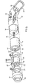
- FIG. 3 shows in detail the support housing, actuating means, motor means and associated parts.
- a motor 31 drives an elongated screw 33 whose opposite end is rotatably held in a recirculating ball-type nut 32.
- a cylindrical slide 35 is connected to the nut 32 and moves linearly under the drive of the screw 33 between the limiting stops 37 and 39, which are locked to the housing A by thumb screws.
- the mechanism is encased in an outer tube 41 and an inner concentric tube 42.
- the tube 41 is provided with a longitudinal slot 43 and the concentric tube 42 with an elongated slot 45.
- the slot 43 accommodates the flange connection 48 between the slide 35 and the plate 25.
- the slot 45 accommodates the flange connection 46 between the ball nut 33 and the slide 35.
- the motor 31 is powered by batteries 47 which operate through circuits on a circuit board 49 and is governed by controls 51.
- the tube 41 is provided with a gooseneck part 53 about which there extends a bracket 55 connecting it to the harness B.
- the other end of the tube 41 has a terminal 56 provided with an eye 57 so that it can be hung from a suitable hook when required.
- the motor 31 is a reversible motor. It will reverse as soon as an excessive load is applied. This may be, for example, where the actuator or traveller reaches the end of its stroke and is halted by the stop 37 or 39 as the case may be. Or, it may be where there is some unplanned obstruction, for example, sheets jamming in the mechanism or where the patient offers undue resistance. A safety function is thus performed as well as a prime actuating function.
- Suitable motors are geared D.C. Brush type motors made by Faulhaber, Escap, and Maxon Precision, all of Switzerland.
- Fig. 4 describes an apparatus for flexing the knee joint. Similar numbers have been applied to similar parts, as on Figs. 1 and 3, with the exception that they have been raised by 100 and the letters have been given a subscript 1.
- the support housing A 1 forms part of a crutch for supporting the patient and embodies operating mechanism similar to that shown in Fig. 3, except that the housing A 1 is straight instead of having a gooseneck end. It has a rubber foot 157 taking the place of the terminal 56.
- a handle B 1 takes the place of the harness B and is provided with an armpit bar 159. The part B 1 slides on the top end of the support housing A l .
- Taking the place of the plate 25 is a simple foot plate with straps, as compared with the supination and pronation mechanism for rotating the wrist.
- Fig. 5 shows an alternative arrangement in which a waistband B 2 is employed to connect the top of a support housing A 2 to the body.
- a separate crutch D supports the patient.
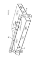
- Fig. 6 illustrates a further form of leg exercising device.
- the support housing of Figs. 4 and 5 is connected to a bed. It is retained by spaced-apart brackets 61 and 62.
- the leg of a patient lying on the bed is connected to the foot plate as in Figs. 4 and 5.
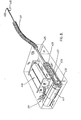
- Fig. 7 illustrates a device for flexing finger or thumb joints.
- a support housing A4 is connected to a cuff B 4 mounted on the wrist and hand in place of the harness of Fig. 1.
- An actuator wire 425 moves back and forth from the housing A4, through a flexible guide tube 441, to a connection with the thumb.
- connection from the actuator wire 425 to the thumb is through a hinge 443 to a small plate 445, adhesively connected to the thumbnail.
- the actuator member 445 can be connected to any of the fingers or several fingers at a time.
- a mechanism for moving the actuator wire 425 is shown in Fig. 8.
- the support structure is fashioned from a block of plastic in which recesses have been made to accommodate the various parts.
- a geared motor 447 drives a sprocket 432 about which there is trained a chain 433 which is also trained about a spaced-apart sprocket 435.
- the actuator wire 425 is connected at 427 to one of the links of the chain 433.
- Batteries 446 are accommodated within the block as is an operating switch 451.
- the motor moves the chain,continuously so that the actuator wire 425 moves in one direction along the top run of the chain and then down along the bottom run in the other direction so as to impart substantially continuous reciprocating movement to the wire 425 and consequently to the hand joint.
Abstract

Description
- . This invention relates to a portable prosthetic device used to treat a human joint by applying "continuous passive motion".
- Dr. Robert B. Salter, Professor and Head of Orthopaedic Surgery at the University of Toronto, and Senior Orthopaedic Surgeon at the Hospital for Sick Children in Toronto, first developed the concept and coined the expression "continuous passive motion". Dr. Salter's work is described in the article "Joints Were Meant to Move - And Move Again" by Ohlendorf in "The Graduate", published by The Department of Information Services, University of Toronto, September/October 1980.
- Briefly, according to this concept, a human joint, for example, a knee, elbow, or finger joint, is kept under slow continuous constrained motion as distinct from being held motionless or being moved intermittently. Keeping an injured or post operative joint mobile rather than immobilizing it in a cast is beneficial to the cartilage.
- Attempts which have been made to provide machines that exercise joints are designed for intermittent operation and do not supply continuous passive motion. Moreover, they are usually too heavy and bulky to be readily portable and thus to be mounted on the body.
- A primary aim of the present invention is to provide an apparatus which imparts continuous motion to the joint and which is portable so that it can be mounted on the patient's body.
- An apparatus, according to the invention, includes a support structure, usually a housing containing working parts. Harness means mounts the support structure on the .patient's body or, in an alternative arrangement, the support structure may be mounted on a crutch or bed. Traveller means is carried by the housing for reciprocating movement relative to it and is connected to an extremity of the limb having the joint to be exercised so that the joint completes the linkage. Motor means in the housing drives the traveller means back and forth through a predetermined stroke with a slow rhythmic motion.
- Having thus generally described the invention, it will be referred to more specifically by reference to the accompanying drawings, which illustrate preferred embodiments, and in which:
- Fig. 1 is a perspective view showing a unit for treating an elbow joint;
- Fig. 2 is a greatly enlarged fragmentary perspective view showing the wrist connection in the unit of Fig. l;
- Fig. 3 is a schematic perspective diagram, of an exploded nature, showing the arrangement of the parts in a unit;
- Fig. 4 is a side elevation showing a unit for treating the knee joint in which the unit forms part of a crutch;
- Fig. 5 is a side elevation of a variation of the unit of Fig. 4;
- Fig. 6 is a fragmentary perspective showing an operating unit for treating the knee joint and which is connected to a bed on which the patient is reclining;
- Fig. 7 is a fragmentary perspective view showing a unit for treating a finger or thumb joint;
- Fig. 8 is a perspective view of the unit shown in Fig. 7, illustrating the drive mechanism.
- Referring more particularly to Fig. 1, the device is made up of a support structure which, in this case, is an elongated housing A connected to the shoulder by a harness B and to the waist by a belt D. Actuator or traveller means, movable relative to the housing, is connected to the wrist by a cuff C. The traveller means is supported by the housing for linear reciprocating movement relative to it. Motor means drives the traveller means back and forth through a predetermined stroke in a slow rhythmic cycle. This imparts a corresponding reciprocating motion to the arm thus imparting continuous passive motion to the elbow joint.
- The speed of movement of the actuator means would, in the embodiment shown, range from one-half foot to four feet per minute, or from one-third to two cycles per minute.
- In order to supply supination and pronation to the wrist, the cuff C is connected (see Fig. 2) to a special mechanism. Mounted for rotation on a
U-shape bracket 15 is a shaft 17, carrying abevel gear 19, which meshes with acrown gear 21, carried on ahub 23, mounted on aplate 25 forming a part of the traveller means. - The
plate 25 moves back and forth, along the housing A, and the flexing of the elbow causes rotation of , the arm at the wrist, by virtue of its connection to thebevel gear 19 as it is caused to ride around the crown gear .21. At the same time, the wrist is held to theplate 25 so that it makes longitudinal movements with the latter along the housing A. - Fig. 3 shows in detail the support housing, actuating means, motor means and associated parts. A
motor 31 drives anelongated screw 33 whose opposite end is rotatably held in a recirculating ball-type nut 32. Acylindrical slide 35 is connected to thenut 32 and moves linearly under the drive of thescrew 33 between thelimiting stops - The mechanism is encased in an
outer tube 41 and an innerconcentric tube 42. Thetube 41 is provided with alongitudinal slot 43 and theconcentric tube 42 with anelongated slot 45. Theslot 43 accommodates theflange connection 48 between theslide 35 and theplate 25. Theslot 45 accommodates theflange connection 46 between theball nut 33 and theslide 35. - The
motor 31 is powered bybatteries 47 which operate through circuits on acircuit board 49 and is governed bycontrols 51. Thetube 41 is provided with agooseneck part 53 about which there extends abracket 55 connecting it to the harness B. The other end of thetube 41 has aterminal 56 provided with aneye 57 so that it can be hung from a suitable hook when required. - The
motor 31 is a reversible motor. It will reverse as soon as an excessive load is applied. This may be, for example, where the actuator or traveller reaches the end of its stroke and is halted by thestop - Examples of suitable motors are geared D.C. Brush type motors made by Faulhaber, Escap, and Maxon Precision, all of Switzerland.
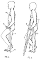
- Fig. 4 describes an apparatus for flexing the knee joint. Similar numbers have been applied to similar parts, as on Figs. 1 and 3, with the exception that they have been raised by 100 and the letters have been given a
subscript 1. - In this case, the support housing A1 forms part of a crutch for supporting the patient and embodies operating mechanism similar to that shown in Fig. 3, except that the housing A1 is straight instead of having a gooseneck end. It has a
rubber foot 157 taking the place of theterminal 56. A handle B1 takes the place of the harness B and is provided with anarmpit bar 159. The part B1 slides on the top end of the support housing Al. Taking the place of theplate 25 is a simple foot plate with straps, as compared with the supination and pronation mechanism for rotating the wrist. - Fig. 5 shows an alternative arrangement in which a waistband B2 is employed to connect the top of a support housing A2 to the body. A separate crutch D supports the patient.
- Fig. 6 illustrates a further form of leg exercising device. In this case, the support housing of Figs. 4 and 5 is connected to a bed. It is retained by spaced-
apart brackets - Fig. 7 illustrates a device for flexing finger or thumb joints. Here again a support housing A4 is connected to a cuff B4 mounted on the wrist and hand in place of the harness of Fig. 1. An
actuator wire 425 moves back and forth from the housing A4, through aflexible guide tube 441, to a connection with the thumb. - The connection from the
actuator wire 425 to the thumb is through ahinge 443 to asmall plate 445, adhesively connected to the thumbnail. Alternatively, theactuator member 445 can be connected to any of the fingers or several fingers at a time. - A mechanism for moving the
actuator wire 425 is shown in Fig. 8. The support structure is fashioned from a block of plastic in which recesses have been made to accommodate the various parts. Ageared motor 447 drives asprocket 432 about which there is trained achain 433 which is also trained about a spaced-apartsprocket 435. Theactuator wire 425 is connected at 427 to one of the links of thechain 433.Batteries 446 are accommodated within the block as is anoperating switch 451. The motor moves the chain,continuously so that theactuator wire 425 moves in one direction along the top run of the chain and then down along the bottom run in the other direction so as to impart substantially continuous reciprocating movement to thewire 425 and consequently to the hand joint. - From this detailed description it will be evident that various modifications can be made within the spirit of the invention to treat various joints of the body under appropriate conditions.
Claims (13)
Priority Applications (1)
| Application Number | Priority Date | Filing Date | Title |
|---|---|---|---|
| AT82302019T ATE28030T1 (en) | 1981-10-23 | 1982-04-20 | DEVICE FOR IMMUNING CONTINUOUS PASSIVE MOTION TO HUMAN JOINTS. |
Applications Claiming Priority (2)
| Application Number | Priority Date | Filing Date | Title |
|---|---|---|---|
| CA388659 | 1981-10-23 | ||
| CA000388659A CA1181306A (en) | 1981-10-23 | 1981-10-23 | Device for imparting continuous passive motion to human joints |
Publications (3)
| Publication Number | Publication Date |
|---|---|
| EP0078093A2 true EP0078093A2 (en) | 1983-05-04 |
| EP0078093A3 EP0078093A3 (en) | 1984-03-28 |
| EP0078093B1 EP0078093B1 (en) | 1987-07-01 |
Family
ID=4121254
Family Applications (1)
| Application Number | Title | Priority Date | Filing Date |
|---|---|---|---|
| EP82302019A Expired EP0078093B1 (en) | 1981-10-23 | 1982-04-20 | Device for imparting continuous passive motion to human joints |
Country Status (6)
| Country | Link |
|---|---|
| US (3) | US4487199A (en) |
| EP (1) | EP0078093B1 (en) |
| JP (1) | JPS58136347A (en) |
| AT (1) | ATE28030T1 (en) |
| CA (1) | CA1181306A (en) |
| DE (1) | DE3276655D1 (en) |
Cited By (5)
| Publication number | Priority date | Publication date | Assignee | Title |
|---|---|---|---|---|
| EP0301605A2 (en) * | 1984-07-10 | 1989-02-01 | Anton Reck | Apparatus using a crank for moving the legs |
| EP0382535A2 (en) * | 1989-02-09 | 1990-08-16 | Danninger Medical Technology, Inc. | Continuous passive motion device for imparting a spiral motion to the digits of the hand |
| EP0460944A1 (en) * | 1990-06-08 | 1991-12-11 | SMITH & NEPHEW RICHARDS, INC. | Dynamic elbow support |
| US5376091A (en) * | 1990-06-08 | 1994-12-27 | Smith & Nephew Richards, Inc. | Dynamic finger support |
| US5683351A (en) * | 1994-09-27 | 1997-11-04 | Jace Systems, Inc. | Continuous passive motion device for a hand |
Families Citing this family (67)
| Publication number | Priority date | Publication date | Assignee | Title |
|---|---|---|---|---|
| CA1181306A (en) * | 1981-10-23 | 1985-01-22 | Toronto Medical Corp. | Device for imparting continuous passive motion to human joints |
| US4665900A (en) * | 1981-10-23 | 1987-05-19 | Toronto Medical Corp. | Device for imparting continuous passive motion to human joints |
| DE3345386A1 (en) * | 1983-12-15 | 1985-06-27 | Ernst Knoll Feinmechanik, 7801 Umkirch | ARM SUPPORT DEVICE |
| US4632393A (en) * | 1985-01-04 | 1986-12-30 | Noord Andrew J Van | Multi-purpose exercising apparatus |
| US4641832A (en) * | 1984-04-24 | 1987-02-10 | Portable Isokinetics, Inc. | Wrist/ankle exercising apparatus |
| US4699376A (en) * | 1984-04-12 | 1987-10-13 | Portable Isokinetics, Inc. | Hip and knee joint exercising apparatus |
| US4665899A (en) * | 1984-09-27 | 1987-05-19 | Joint Mobilizer Systems Corp. | Apparatus for articulating the knee and hip joints |
| US4651719A (en) * | 1985-01-22 | 1987-03-24 | Danninger Medical Technology, Inc. | Continuous passive motion shoulder unit |
| US4644938A (en) * | 1985-01-22 | 1987-02-24 | Danninger Medical Technology | Hand exerciser |
| US4671257A (en) * | 1985-01-23 | 1987-06-09 | Invacare Corporation | Continuous passive motion exercise apparatus |
| US4696469A (en) * | 1986-01-21 | 1987-09-29 | Elder Michael G | Hamstring muscle exerciser |
| US4899735A (en) * | 1988-12-07 | 1990-02-13 | Bissell Health Care Corporation | Torsion bar splint for forearm |
| US4945902A (en) * | 1988-12-15 | 1990-08-07 | Bissell Health Care Corporation | Progressive static flexion device for phalanges |
| US4974830A (en) * | 1989-01-19 | 1990-12-04 | Sutter Corporation | Continuous passive motion device |
| US5252102A (en) * | 1989-01-24 | 1993-10-12 | Electrobionics Corporation | Electronic range of motion apparatus, for orthosis, prosthesis, and CPM machine |
| GB2233900A (en) * | 1989-06-15 | 1991-01-23 | Protectair Ltd | Orthopaedic brace having adjustably pivotal body support member. |
| US5010878A (en) * | 1989-08-29 | 1991-04-30 | Kline Joel L | Apparatus for mobilizing a patient's toes |
| US5178137A (en) * | 1990-03-16 | 1993-01-12 | Motus, Inc. | Segmented dynamic splint |
| US5144943A (en) * | 1990-03-16 | 1992-09-08 | O-Motus, Inc. | Dynamic ankle splint |
| US5179939A (en) * | 1990-08-27 | 1993-01-19 | Sutter Corporation | Passive anatomic shoulder exerciser |
| US5094226A (en) * | 1990-10-31 | 1992-03-10 | Mark T. Medcalf | Continuous passive motion device for the first metatarsal phalangeal joint |
| US5176594A (en) * | 1991-07-05 | 1993-01-05 | Lee Dennis S | Apparatus and method for manipulation of temporomandibular joint |
| US5255188A (en) * | 1991-09-16 | 1993-10-19 | Jace Systems, Inc. | Universal controller for continuous passive motion devices |
| JPH0554329U (en) * | 1991-12-26 | 1993-07-20 | 株式会社イナバエクステリア | Beverage container |
| US5297540A (en) * | 1992-01-29 | 1994-03-29 | Jace Systems, Inc. | Continuous passive motion orthosis device for a toe |
| US5333604A (en) * | 1992-09-16 | 1994-08-02 | Sutter Corporation | Patella exercising apparatus |
| US5267924A (en) * | 1993-01-07 | 1993-12-07 | Advanced Kinetics, Inc. | Apparatus and method for imparting continuous passive motion to the foot |
| US5458560A (en) * | 1993-09-03 | 1995-10-17 | Jace Systems, Inc. | Continuous passive motion device for a wrist |
| US5472407A (en) * | 1993-10-13 | 1995-12-05 | Schenck; Robert R. | Motorized dynamic traction device |
| US5716330A (en) * | 1995-07-13 | 1998-02-10 | Goldman; David A. | Body and limb position/motion detector and power assist apparatus and method |
| US5746704A (en) * | 1995-08-04 | 1998-05-05 | Schenck; Robert R. | Therapy apparatus having a passive motion device for flexing a body member |
| US5865770A (en) * | 1995-12-06 | 1999-02-02 | Schectman; Leonard A. | Device to counteract paralysis |
| US5848979A (en) * | 1996-07-18 | 1998-12-15 | Peter M. Bonutti | Orthosis |
| US5951499A (en) * | 1996-09-27 | 1999-09-14 | Orthologic Corp. | Continuous passive motion device for upper extremity forearm therapy |
| JP4051505B2 (en) * | 1997-03-07 | 2008-02-27 | 株式会社安川電機 | Medical equipment |
| US6019740A (en) * | 1997-12-19 | 2000-02-01 | Hausman; John M. | Actuator driven stretching and exercise device |
| US6113562A (en) | 1998-06-01 | 2000-09-05 | Peter M. Bonutti | Shoulder orthosis |
| US6872187B1 (en) * | 1998-09-01 | 2005-03-29 | Izex Technologies, Inc. | Orthoses for joint rehabilitation |
| US7416537B1 (en) * | 1999-06-23 | 2008-08-26 | Izex Technologies, Inc. | Rehabilitative orthoses |
| US6221032B1 (en) | 1999-11-09 | 2001-04-24 | Chattanooga Group, Inc. | Continuous passive motion device having a rehabilitation enhancing mode of operation |
| US6221033B1 (en) | 1999-11-09 | 2001-04-24 | Chattanooga Group, Inc. | Continuous passive motion device that accelerates through the non-working range of motion |
| US6267735B1 (en) | 1999-11-09 | 2001-07-31 | Chattanooga Group, Inc. | Continuous passive motion device having a comfort zone feature |
| US6217532B1 (en) | 1999-11-09 | 2001-04-17 | Chattanooga Group, Inc. | Continuous passive motion device having a progressive range of motion |
| US7004043B2 (en) * | 2000-04-04 | 2006-02-28 | Videolarm, Inc. | Elevated support pole with automatic electrical connection and disconnection |
| US6447150B1 (en) * | 2000-04-04 | 2002-09-10 | Videolarm, Inc. | Pole with lifting mount |
| US6502577B1 (en) * | 2000-09-18 | 2003-01-07 | Peter M. Bonutti | Method for moving finger joints |
| US6503213B2 (en) * | 2000-12-01 | 2003-01-07 | Peter M. Bonutti | Method of using a neck brace |
| US6575926B2 (en) * | 2000-12-15 | 2003-06-10 | Bonutti 2003 Trust-A | Myofascial strap |
| US7066896B1 (en) | 2002-11-12 | 2006-06-27 | Kiselik Daniel R | Interactive apparatus and method for developing ability in the neuromuscular system |
| US7452342B2 (en) | 2004-03-08 | 2008-11-18 | Bonutti Research Inc. | Range of motion device |
| US8066656B2 (en) | 2005-10-28 | 2011-11-29 | Bonutti Research, Inc. | Range of motion device |
| US20060041205A1 (en) * | 2004-08-17 | 2006-02-23 | Ladd Larry D Jr | ISOROM portable isometric and passive range of motion device |
| US7309320B2 (en) * | 2004-09-17 | 2007-12-18 | Ana-Tek, Llc | Apparatus and method for supporting and continuously flexing a jointed limb |
| US7727119B2 (en) * | 2004-09-27 | 2010-06-01 | Therapease Innovation, Llc | Human self-powered joint exerciser apparatus |
| WO2006055547A2 (en) * | 2004-11-15 | 2006-05-26 | Izex Technologies, Inc. | Instrumented orthopedic and other medical implants |
| US8308794B2 (en) | 2004-11-15 | 2012-11-13 | IZEK Technologies, Inc. | Instrumented implantable stents, vascular grafts and other medical devices |
| US20060271043A1 (en) * | 2005-05-27 | 2006-11-30 | Gonzalez Lupe A | User-attached, manually operated fluid-driven arm lift device |
| US8012108B2 (en) | 2005-08-12 | 2011-09-06 | Bonutti Research, Inc. | Range of motion system and method |
| WO2008097989A2 (en) | 2007-02-05 | 2008-08-14 | Bonutti Research Inc. | Knee orthosis |
| EP2178475A1 (en) * | 2007-07-25 | 2010-04-28 | Bonutti Research Inc. | Orthosis apparatus and method of using an orthosis apparatus |
| US8905950B2 (en) | 2008-03-04 | 2014-12-09 | Bonutti Research, Inc. | Shoulder ROM orthosis |
| US9402759B2 (en) | 2013-02-05 | 2016-08-02 | Bonutti Research, Inc. | Cervical traction systems and method |
| US20200368057A1 (en) * | 2015-06-25 | 2020-11-26 | Pascal Boileau | Upper Extremity Braces |
| EP3108859B1 (en) * | 2015-06-25 | 2019-05-22 | Pascal Boileau | Improvements in or relating to upper extremity braces |
| JP6979001B2 (en) * | 2017-10-20 | 2021-12-08 | パナソニック株式会社 | Exercise assistance system and rehabilitation support system |
| CN112618249B (en) * | 2019-10-08 | 2021-09-28 | 复旦大学 | Active and passive hand rehabilitation training robot |
| US11918504B1 (en) | 2019-11-13 | 2024-03-05 | Preferred Prescription, Inc. | Orthotic device to prevent hyperextension |
Citations (5)
| Publication number | Priority date | Publication date | Assignee | Title |
|---|---|---|---|---|
| DE191678C (en) * | ||||
| US3323518A (en) * | 1964-04-10 | 1967-06-06 | Howard M Swanson | Device for inducing motion to a joint |
| FR2109426A5 (en) * | 1970-10-16 | 1972-05-26 | Masmonteil Henri | |
| US3824994A (en) * | 1973-01-29 | 1974-07-23 | R S Reciprocating Trainer Ente | Reciprocating walker |
| US3976057A (en) * | 1974-12-23 | 1976-08-24 | Clarence F. Bates | Joint flexing apparatus |
Family Cites Families (12)
| Publication number | Priority date | Publication date | Assignee | Title |
|---|---|---|---|---|
| US2832334A (en) * | 1956-05-23 | 1958-04-29 | Stephen H Whitelaw | Therapeutic device for use in manipulative treatment of joints of the human body |
| US3220718A (en) * | 1963-05-09 | 1965-11-30 | Republic Industries | Door operator |
| US3546930A (en) * | 1968-11-25 | 1970-12-15 | Clarence A Flarsheim | Rotary to linear motion device with automatic return |
| GB1310492A (en) * | 1968-12-05 | 1973-03-21 | Flowtron Aire Ltd | Apparatus for activating parts of the body |
| US3661149A (en) * | 1970-05-27 | 1972-05-09 | Charles A Ferries | Mechanical exercising device |
| US3816016A (en) * | 1972-11-09 | 1974-06-11 | Avey Machine Tool Co | Power drilling machine with resistance triggered retraction |
| SU644469A1 (en) * | 1975-07-18 | 1979-01-30 | Центральный Ордена Трудового Красного Знамени Научно-Исследовательский Институт Травматологии И Ортопедии Им. Н.Н.Приорова | Apparatus for restoring the mobility of joints |
| US4077268A (en) * | 1976-07-14 | 1978-03-07 | Hill John W | Garage door operator |
| US4177804A (en) * | 1977-02-28 | 1979-12-11 | Fred Weingarten | Automatic massaging device |
| US4282865A (en) * | 1979-08-13 | 1981-08-11 | Pogue William F | Apparatus for exercising a limb of a patient |
| SU848027A1 (en) * | 1979-11-12 | 1981-07-23 | за вители I. .. .: ; 1.. . .. | Electromechanical device for exercising joints of lower extremities |
| CA1181306A (en) * | 1981-10-23 | 1985-01-22 | Toronto Medical Corp. | Device for imparting continuous passive motion to human joints |
-
1981
- 1981-10-23 CA CA000388659A patent/CA1181306A/en not_active Expired
-
1982
- 1982-03-29 US US06/362,896 patent/US4487199A/en not_active Expired - Lifetime
- 1982-04-20 DE DE8282302019T patent/DE3276655D1/en not_active Expired
- 1982-04-20 EP EP82302019A patent/EP0078093B1/en not_active Expired
- 1982-04-20 AT AT82302019T patent/ATE28030T1/en not_active IP Right Cessation
- 1982-09-21 JP JP57164806A patent/JPS58136347A/en active Granted
-
1984
- 1984-10-15 US US06/660,704 patent/US4537083A/en not_active Expired - Lifetime
-
1985
- 1985-08-22 US US06/768,518 patent/US4716889A/en not_active Expired - Lifetime
Patent Citations (5)
| Publication number | Priority date | Publication date | Assignee | Title |
|---|---|---|---|---|
| DE191678C (en) * | ||||
| US3323518A (en) * | 1964-04-10 | 1967-06-06 | Howard M Swanson | Device for inducing motion to a joint |
| FR2109426A5 (en) * | 1970-10-16 | 1972-05-26 | Masmonteil Henri | |
| US3824994A (en) * | 1973-01-29 | 1974-07-23 | R S Reciprocating Trainer Ente | Reciprocating walker |
| US3976057A (en) * | 1974-12-23 | 1976-08-24 | Clarence F. Bates | Joint flexing apparatus |
Cited By (7)
| Publication number | Priority date | Publication date | Assignee | Title |
|---|---|---|---|---|
| EP0301605A2 (en) * | 1984-07-10 | 1989-02-01 | Anton Reck | Apparatus using a crank for moving the legs |
| EP0301605A3 (en) * | 1984-07-10 | 1989-02-08 | Anton Reck | Apparatus using a crank for moving the legs |
| EP0382535A2 (en) * | 1989-02-09 | 1990-08-16 | Danninger Medical Technology, Inc. | Continuous passive motion device for imparting a spiral motion to the digits of the hand |
| EP0382535A3 (en) * | 1989-02-09 | 1991-03-27 | Danninger Medical Technology, Inc. | Continuous passive motion device for imparting a spiral motion to the digits of the hand |
| EP0460944A1 (en) * | 1990-06-08 | 1991-12-11 | SMITH & NEPHEW RICHARDS, INC. | Dynamic elbow support |
| US5376091A (en) * | 1990-06-08 | 1994-12-27 | Smith & Nephew Richards, Inc. | Dynamic finger support |
| US5683351A (en) * | 1994-09-27 | 1997-11-04 | Jace Systems, Inc. | Continuous passive motion device for a hand |
Also Published As
| Publication number | Publication date |
|---|---|
| CA1181306A (en) | 1985-01-22 |
| ATE28030T1 (en) | 1987-07-15 |
| EP0078093B1 (en) | 1987-07-01 |
| US4716889A (en) | 1988-01-05 |
| EP0078093A3 (en) | 1984-03-28 |
| DE3276655D1 (en) | 1987-08-06 |
| JPS58136347A (en) | 1983-08-13 |
| US4537083A (en) | 1985-08-27 |
| US4487199A (en) | 1984-12-11 |
| JPH0414028B2 (en) | 1992-03-11 |
Similar Documents
| Publication | Publication Date | Title |
|---|---|---|
| US4487199A (en) | Device for imparting continuous passive motion to human joints | |
| CN108309694B (en) | Foot-driven lower limb rehabilitation training device | |
| US4665900A (en) | Device for imparting continuous passive motion to human joints | |
| US4724827A (en) | Dynamic traction device | |
| CN102327173B (en) | Wearable exoskeleton lower limb rehabilitation robot | |
| US5280783A (en) | Continuous passive motion device for full extension of leg | |
| CN111281741B (en) | Reconfigurable exoskeleton upper limb rehabilitation robot for different body types | |
| CN106983634A (en) | A kind of exoskeleton finger functional rehabilitation device based on multistage continuous structure | |
| CN109248408A (en) | A kind of whole body healing robot | |
| US3323518A (en) | Device for inducing motion to a joint | |
| AU740656B2 (en) | Device for producing continuous passive motion | |
| CN112451310B (en) | Restorer is tempered to orthopedics joint muscle power | |
| CN109771222A (en) | A kind of finger gymnastic robot with interior receipts outreach function | |
| CN114145961B (en) | Intelligent multifunctional upper limb rehabilitation all-in-one machine | |
| JP2002119555A (en) | Rehabilitation apparatus | |
| CN111759662A (en) | Arm auxiliary device | |
| CN209122796U (en) | A kind of lower limb rehabilitation robot of seven freedom | |
| CA1224687A (en) | Device for imparting continuous passive motion to human joints | |
| CN209123286U (en) | A kind of whole body healing robot | |
| CN210903943U (en) | Multi-angle double-foot automatic ankle pump movement device | |
| CN2354545Y (en) | Instrument for treating upper limb | |
| CN111938988A (en) | Wearable five-degree-of-freedom exoskeleton upper limb rehabilitation robot | |
| CN2239830Y (en) | Multi-functional bedside limb joint exercising apparatus | |
| RU197742U1 (en) | MIRROR SIMULATOR | |
| CN216536718U (en) | Multifunctional active and passive rehabilitation training device |
Legal Events
| Date | Code | Title | Description |
|---|---|---|---|
| PUAI | Public reference made under article 153(3) epc to a published international application that has entered the european phase |
Free format text: ORIGINAL CODE: 0009012 |
|
| AK | Designated contracting states |
Designated state(s): AT BE CH DE FR GB IT LI LU NL SE |
|
| PUAL | Search report despatched |
Free format text: ORIGINAL CODE: 0009013 |
|
| AK | Designated contracting states |
Designated state(s): AT BE CH DE FR GB IT LI LU NL SE |
|
| 16A | New documents despatched to applicant after publication of the search report | ||
| 17P | Request for examination filed |
Effective date: 19840828 |
|
| RAP1 | Party data changed (applicant data changed or rights of an application transferred) |
Owner name: TORONTO MEDICAL CORP. |
|
| GRAA | (expected) grant |
Free format text: ORIGINAL CODE: 0009210 |
|
| AK | Designated contracting states |
Kind code of ref document: B1 Designated state(s): AT BE CH DE FR GB IT LI LU NL SE |
|
| REF | Corresponds to: |
Ref document number: 28030 Country of ref document: AT Date of ref document: 19870715 Kind code of ref document: T |
|
| ET | Fr: translation filed | ||
| REF | Corresponds to: |
Ref document number: 3276655 Country of ref document: DE Date of ref document: 19870806 |
|
| ITF | It: translation for a ep patent filed |
Owner name: SAIC BREVETTI S.R.L. |
|
| PLBI | Opposition filed |
Free format text: ORIGINAL CODE: 0009260 |
|
| 26 | Opposition filed |
Opponent name: COMPAGNIE GENERALE DE MATERIEL ORTHOPEDIQUE SOCIET Effective date: 19880324 |
|
| NLR1 | Nl: opposition has been filed with the epo |
Opponent name: COMPAGNIE GENERALE DE MATERIEL ORTHOPEDIQUE SOCIET |
|
| ITTA | It: last paid annual fee | ||
| PGFP | Annual fee paid to national office [announced via postgrant information from national office to epo] |
Ref country code: SE Payment date: 19910410 Year of fee payment: 10 |
|
| PGFP | Annual fee paid to national office [announced via postgrant information from national office to epo] |
Ref country code: GB Payment date: 19910411 Year of fee payment: 10 |
|
| PGFP | Annual fee paid to national office [announced via postgrant information from national office to epo] |
Ref country code: LU Payment date: 19910424 Year of fee payment: 10 |
|
| PGFP | Annual fee paid to national office [announced via postgrant information from national office to epo] |
Ref country code: CH Payment date: 19910429 Year of fee payment: 10 Ref country code: BE Payment date: 19910429 Year of fee payment: 10 Ref country code: AT Payment date: 19910429 Year of fee payment: 10 |
|
| PGFP | Annual fee paid to national office [announced via postgrant information from national office to epo] |
Ref country code: NL Payment date: 19910430 Year of fee payment: 10 Ref country code: FR Payment date: 19910430 Year of fee payment: 10 |
|
| PGFP | Annual fee paid to national office [announced via postgrant information from national office to epo] |
Ref country code: DE Payment date: 19910508 Year of fee payment: 10 |
|
| EPTA | Lu: last paid annual fee | ||
| RDAG | Patent revoked |
Free format text: ORIGINAL CODE: 0009271 |
|
| STAA | Information on the status of an ep patent application or granted ep patent |
Free format text: STATUS: PATENT REVOKED |
|
| REG | Reference to a national code |
Ref country code: CH Ref legal event code: PL |
|
| 27W | Patent revoked |
Effective date: 19911017 |
|
| GBPR | Gb: patent revoked under art. 102 of the ep convention designating the uk as contracting state | ||
| NLR2 | Nl: decision of opposition | ||
| BERE | Be: lapsed |
Owner name: TORONTO MEDICAL CORP. Effective date: 19920430 |
|
| EUG | Se: european patent has lapsed |
Ref document number: 82302019.3 Effective date: 19920205 |
|
| APAH | Appeal reference modified |
Free format text: ORIGINAL CODE: EPIDOSCREFNO |