EP0084423A2 - Cervical traction apparatus - Google Patents
Cervical traction apparatus Download PDFInfo
- Publication number
- EP0084423A2 EP0084423A2 EP83300112A EP83300112A EP0084423A2 EP 0084423 A2 EP0084423 A2 EP 0084423A2 EP 83300112 A EP83300112 A EP 83300112A EP 83300112 A EP83300112 A EP 83300112A EP 0084423 A2 EP0084423 A2 EP 0084423A2
- Authority
- EP
- European Patent Office
- Prior art keywords
- patient
- head
- traction
- carriage
- traction force
- Prior art date
- Legal status (The legal status is an assumption and is not a legal conclusion. Google has not performed a legal analysis and makes no representation as to the accuracy of the status listed.)
- Granted
Links
Images

Classifications
-
- A—HUMAN NECESSITIES
- A61—MEDICAL OR VETERINARY SCIENCE; HYGIENE
- A61H—PHYSICAL THERAPY APPARATUS, e.g. DEVICES FOR LOCATING OR STIMULATING REFLEX POINTS IN THE BODY; ARTIFICIAL RESPIRATION; MASSAGE; BATHING DEVICES FOR SPECIAL THERAPEUTIC OR HYGIENIC PURPOSES OR SPECIFIC PARTS OF THE BODY
- A61H1/00—Apparatus for passive exercising; Vibrating apparatus ; Chiropractic devices, e.g. body impacting devices, external devices for briefly extending or aligning unbroken bones
- A61H1/02—Stretching or bending or torsioning apparatus for exercising
- A61H1/0218—Drawing-out devices
-
- A—HUMAN NECESSITIES
- A61—MEDICAL OR VETERINARY SCIENCE; HYGIENE
- A61H—PHYSICAL THERAPY APPARATUS, e.g. DEVICES FOR LOCATING OR STIMULATING REFLEX POINTS IN THE BODY; ARTIFICIAL RESPIRATION; MASSAGE; BATHING DEVICES FOR SPECIAL THERAPEUTIC OR HYGIENIC PURPOSES OR SPECIFIC PARTS OF THE BODY
- A61H2201/00—Characteristics of apparatus not provided for in the preceding codes
- A61H2201/16—Physical interface with patient
- A61H2201/1602—Physical interface with patient kind of interface, e.g. head rest, knee support or lumbar support
- A61H2201/1604—Head
- A61H2201/1607—Holding means therefor
Definitions
- the present invention relates to a cervical traction apparatus and method used to administer traction to patients with various musculoskeletal disorders of the neck and upper back.
- the apparatus of the present invention is designed to be utilized with a conventional traction table with the patient in the supine position, wherein the patient is lying substantially horizontal on his back.
- Another object of the present invention is to provide a cervical traction apparatus and method which engages the rear of the head while leaving the mouth and jaw of the patient unrestricted.
- Another object of the present invention is to provide an improved and simplified traction apparatus and method having provision for varying the vertical and lateral angles of traction pull relative to the mid-line of the patient's body.
- Another object of the present invention is to provide a simplified cervical traction apparatus and method which is very versatile, easily adjusted to various patients, and more comfortable for the person wearing same,
- a therapeutic traction apparatus which includes a track adapted to be positioned longitudinally on a traction table or the like, a carriage mounted for longitudinal movement along the track, and body engaging means mounted to the carriage for engaging the head of the patient in the occiput area.
- a traction force is applied to the carriage in the longitudinal direction, and the force is transferred to the occipital area of the head of the patient and in general alignment with the spine.
- the body engaging means includes a pair of V-shaped adjustable arms which grip the rear area of the patient's head approximate the occipital bone and mastoid processes.
- the V-shaped arms are laterally adjustable to fit patients of varying size, as well as being pivotally mounted so that the traction force on one side of the spine can be greater or lesser.
- the V-shaped arms are carried on the carriage which in turn is attached to traction weights or a mechanical traction machine through a rope and pulley arrangement so as to apply a variable traction force.
- the carriage is slideably mounted on the track, which in turn is anchored at one end near the traction source while the opposite end rests on the surface of the table.
- the flexion-extension angle (rope angle to the table) can be changed by raising or lowering the height of the attachment point of the carriage to the track.
- the lateral angle can be varied by moving the traction source, namely the rope, pulley and weights, or mechanical traction machine, from side to side.
- the purpose of administering a traction force at an angle lateral to the mid-line of the spine is to concentrate greater force to one side of the spine than the other for particular disorders.
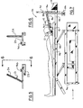
- figure 7 illustrates a conventional traction table 11, with the traction device of the present invention generally described by reference numeral 10 mounted at its right end.
- Table 11 illustrated is merely typical of numerous well-known designs which are on the market and all of which can be readily used with the device 10 of the present invention.
- Table 11 includes a base 30 for supporting a frame 32 which in turn carries a pad 33 on which the patient lies. Attached to the right end of support frame 32 is an anchor post 34 which carries the traction weights 35, and the traction device 10 of the present invention. In place of weights 35, a conventional traction machine 9 can be used, which also attaches to the right end of frame 32.
- the various details of the traction table 11 or traction machine 9 are not described in detail since they are well-known in the prior art, and are not a part of the present invention.
- Bracket 36 Adjustably positioned on post 34 is a bracket 36 which slides up and down and is held in place by set screw 37, as seen in Figure 1. Passing through bracket 36 is a bolt 38 which has a dual function in providing an axle for the pulley traction rope 40, and also providing a releasable attachment point for the traction device 10 of the present invention.
- the traction device 10 attaches directly to the traction machine which can itself be adjusted vertically and laterally.
- Traction device 10 comprises a hollow square tubular shaft 12 which acts as a track means for carriage 14 as it slides back and forth thereon.
- the upper end of shaft 12 includes a traverse slot 42 for engaging bracket 36 through bolt 38, as been seen in Figures 1 and 2.
- Shaft 12 includes a telescoping section 44 which allows the shaft 12 to be extended when desired by loosening and retightening screw 46.
- Attached to carriage 14 is rope 40 which transmits the variable force of traction weights 35 to the carriage 14 along whatever angle the shaft 12 is positioned relative to the top of table 11.
- Attached to the lower end of shaft 12 are lateral support legs 13, as best seen in Figure 1, which rest upon the top surface of the traction table pad 33.
- Carriage 14 comprises a box section tube with an interior dimension slightly greater than shaft 12, and supports thereon a pair of lateral extension members 15, which are seen in detail in Figure 4. Extensions 15 in turn carry a pair of canted arms 20 and 21 which slide laterally back and forth across extensions 15. The various positions of arms 20 and 21 are determined by holes 48 in extensions 15 and locking pins 50. Lateral extensions 15 can also be made adjustable and rotated about bolt 52 to the dotted line position of Figure 4 by the removal of bolt 54 from carriage 14. Arms 20 and 21 include rigid rods 22 and 24 anchored to a pair of base members 23 which in turn slide on extensions 15. Positioned over rods 22 and 24 are a pair of circular sponge covers 25 which contact and grip the back of the patient's head in the occiput area.
- Arms 20 and 21 are adjusted on extensions 15 so that the arms contact the occipital bone approximate the back of the patient's head, as illustrated in Figure 3. As best seen in Figure 3, the arms are disposed at an angle of about 60° to each other, in any laterally adjusted position.
- a head support pad 16 which includes on both sides thereof a head band or strap 18 which releasably fits around the patient's forehead and maintains the head in contacting relationship with pad 16 and arms 20 and 21.
- the strap 18 prevents movement of the head in a direction lateral to the direction of the traction force.
- the head support pad 16 may if desired be directly connected to extension members 15, so that when rotated about bolt 52 they both retain the relative positions to each other.
- the arms 20 and 21 are shown to be straight in Figure 3; however, they can also be shaped with a slight degree of concavity, when viewed from the Figure 3 position.
- the shaft 12 could have a different cross- sectional shape, such as an "I" beam.
- the particular flexion extension angle (the rope angle to the table) which is desired for the particular patient, is set by releasing set screw 37 and sliding bracket 36 up or down to the proper vertical position, and resetting.
- the flexion extension angle can also be adjusted by releasing screw 46 and allowing the telescoping section 44 of shaft 12 to extend, which decreases the flexion angle.
- the support legs 13, at the end of shaft 12, can rest at any position on table pad 33, as seen in Figure 7.
- the V-shaped arms 20 and 21 are adjustably positioned around the patient's head so that the arms contact the occipital bone at the base of the patient's head, while the back of the patient's head rests on pad 16.
- the support strap 18 is snugly fastened around the patient's forehead.
- the patient may if desired be anchored to the traction table 11 by various adjustable belts, not shown in the drawing.
- the amount of traction force applied to the patient is varied by changing the amount of weight 35 attached to rope 40, or by adjusting the amount of force set on the mechanical traction machine 9. If it is desirous to apply more traction force to one side of the patient's spine than the other, the extension members 15 are rotated to a dotted line position, as indicated in Figure 4, by the removal and replacement of bolt 54.
- a lateral offset tractive force can also be accomplished by providing bracket 36 with a universal joint so that anchor post 34 can be moved or tilted to one side of the mid-line spinal axis of the patient.
- the tractive force is applied to the patient's head through the V-shaped arms 20 and 21 along the occipital line and mastoid processes. This is more comfortable for the patient and also concentrates the force posteriorly and in alignment with the spine where it is most beneficial.
Abstract
Description
- The present invention relates to a cervical traction apparatus and method used to administer traction to patients with various musculoskeletal disorders of the neck and upper back. The apparatus of the present invention is designed to be utilized with a conventional traction table with the patient in the supine position, wherein the patient is lying substantially horizontal on his back.
- In the prior art there have been a substantial number of head halters or other devices for applying cervical traction through the head of the patient. One category of these halter devices, such as shown in U.S. patents Nos. 1,301,276 and 3,548,817, engages the jaw of the patient while surrounding the head. These types of halters not only inhibit the ability of the'patient to eat or talk, but also cause aggravation of the temporomandibular (jaw) joints, and from a traction point of view are also less desirable. Jaw-type head halters of this type pull from an axis offset from the spine and thereby apply an undesirable twisting moment (cervical extension) to the patient's head and neck contrary to most types of desired traction. In most traction situations, it is desirable to engage the head of the patient at the occiput area of the head rather than the chin so that the pulling axis is more in alignment with the spine and concentrates the force posteriorly where it is most beneficial.
- Another type of prior art device for engaging the head is typified in U.S. Patents Nos. 2,166,229 and 3,336,922. These types of cervical braces, which are referred to in the trade as "halo type" actually contact the patient's head with pointed screws which are forced inwardly through the skin to make contact with the bone of the skull. Aside from the obvious pain which a patient must endure by this type of brace, the potential for infection to the person's head at the points where the skin is broken is ever present.
- It is an object of the present invention to provide a dynamic traction apparatus and method which applies the traction force to the patient's head along the occipital line and mastoid processes, and which results in the force being applied along a line in general alignment with the spine.
- Another object of the present invention is to provide a cervical traction apparatus and method which engages the rear of the head while leaving the mouth and jaw of the patient unrestricted.
- Another object of the present invention is to provide an improved and simplified traction apparatus and method having provision for varying the vertical and lateral angles of traction pull relative to the mid-line of the patient's body.
- Another object of the present invention is to provide a simplified cervical traction apparatus and method which is very versatile, easily adjusted to various patients, and more comfortable for the person wearing same,
- "These and other objects and advantages are achieved in the present invention by the provision of a therapeutic traction apparatus which includes a track adapted to be positioned longitudinally on a traction table or the like, a carriage mounted for longitudinal movement along the track, and body engaging means mounted to the carriage for engaging the head of the patient in the occiput area. In use, a traction force is applied to the carriage in the longitudinal direction, and the force is transferred to the occipital area of the head of the patient and in general alignment with the spine.
- In the specific illustrated embodiment, the body engaging means includes a pair of V-shaped adjustable arms which grip the rear area of the patient's head approximate the occipital bone and mastoid processes. The V-shaped arms are laterally adjustable to fit patients of varying size, as well as being pivotally mounted so that the traction force on one side of the spine can be greater or lesser. The V-shaped arms are carried on the carriage which in turn is attached to traction weights or a mechanical traction machine through a rope and pulley arrangement so as to apply a variable traction force. There is also a small headrest pad mounted on the carriage for supporting the back of the patient's head and an adjustable strap is attached to the carriage for surrounding and holding the patient's head in contact with the pad. The carriage is slideably mounted on the track, which in turn is anchored at one end near the traction source while the opposite end rests on the surface of the table. The flexion-extension angle (rope angle to the table) can be changed by raising or lowering the height of the attachment point of the carriage to the track. Also, the lateral angle can be varied by moving the traction source, namely the rope, pulley and weights, or mechanical traction machine, from side to side. The purpose of administering a traction force at an angle lateral to the mid-line of the spine is to concentrate greater force to one side of the spine than the other for particular disorders.
- For the purpose of illustrating the invention, there is shown in the drawings a form which is presently preferred; however, it is understood that the invention is not limited to the precise arrangement as shown in the drawings.-
- FIGURE 1 is a top plan view of the cervical traction device shown mounted to the anchor post of a conventional traction table;
- FIGURE 2 is a side elevational view taken along line 2-2 of FIG. 1;
- FIGURE 3 is a sectional view taken along line 3-3 of FIG. 2;
- FIGURE 4 is a partial top plan view taken along line 4-4 of FIG. 3, with the lateral extensions shown in an alternate dotted line position;
- FIGURE 5 is a detailed side elevational view of a canted arm with the cushion cover removed;
- FIGURE 6 is an elevational view taken along line 6-6 of FIG. 5; and
- FIGURE 7 is a side elevational view of a conventional traction table with the traction device of the present invention shown thereon.
- Referring to the drawings in detail, figure 7 illustrates a conventional traction table 11, with the traction device of the present invention generally described by
reference numeral 10 mounted at its right end. The table 11 illustrated is merely typical of numerous well-known designs which are on the market and all of which can be readily used with thedevice 10 of the present invention. Table 11 includes abase 30 for supporting aframe 32 which in turn carries apad 33 on which the patient lies. Attached to the right end ofsupport frame 32 is ananchor post 34 which carries thetraction weights 35, and thetraction device 10 of the present invention. In place ofweights 35, aconventional traction machine 9 can be used, which also attaches to the right end offrame 32. The various details of the traction table 11 ortraction machine 9 are not described in detail since they are well-known in the prior art, and are not a part of the present invention. - Adjustably positioned on
post 34 is abracket 36 which slides up and down and is held in place by setscrew 37, as seen in Figure 1. Passing throughbracket 36 is abolt 38 which has a dual function in providing an axle for thepulley traction rope 40, and also providing a releasable attachment point for thetraction device 10 of the present invention. - In another type of conventional traction table and mechanical traction machine (not shown in the drawing), the
traction device 10 attaches directly to the traction machine which can itself be adjusted vertically and laterally. -
Traction device 10 comprises a hollow squaretubular shaft 12 which acts as a track means forcarriage 14 as it slides back and forth thereon. The upper end ofshaft 12 includes a traverse slot 42 forengaging bracket 36 throughbolt 38, as been seen in Figures 1 and 2.Shaft 12 includes a telescoping section 44 which allows theshaft 12 to be extended when desired by loosening andretightening screw 46. Attached tocarriage 14 isrope 40 which transmits the variable force oftraction weights 35 to thecarriage 14 along whatever angle theshaft 12 is positioned relative to the top of table 11. Attached to the lower end ofshaft 12 arelateral support legs 13, as best seen in Figure 1, which rest upon the top surface of thetraction table pad 33. -
Carriage 14 comprises a box section tube with an interior dimension slightly greater thanshaft 12, and supports thereon a pair oflateral extension members 15, which are seen in detail in Figure 4.Extensions 15 in turn carry a pair of cantedarms extensions 15. The various positions ofarms extensions 15 andlocking pins 50.Lateral extensions 15 can also be made adjustable and rotated aboutbolt 52 to the dotted line position of Figure 4 by the removal ofbolt 54 fromcarriage 14.Arms rigid rods 22 and 24 anchored to a pair ofbase members 23 which in turn slide onextensions 15. Positioned overrods 22 and 24 are a pair of circular sponge covers 25 which contact and grip the back of the patient's head in the occiput area.Arms extensions 15 so that the arms contact the occipital bone approximate the back of the patient's head, as illustrated in Figure 3. As best seen in Figure 3, the arms are disposed at an angle of about 60° to each other, in any laterally adjusted position. - Also attached to
carriage 14 is a head support pad 16 which includes on both sides thereof a head band orstrap 18 which releasably fits around the patient's forehead and maintains the head in contacting relationship with pad 16 andarms strap 18 prevents movement of the head in a direction lateral to the direction of the traction force. The head support pad 16 may if desired be directly connected toextension members 15, so that when rotated aboutbolt 52 they both retain the relative positions to each other. - The
arms - Also, the
shaft 12 could have a different cross- sectional shape, such as an "I" beam. - The particular flexion extension angle (the rope angle to the table) which is desired for the particular patient, is set by releasing set
screw 37 and slidingbracket 36 up or down to the proper vertical position, and resetting. The flexion extension angle can also be adjusted by releasingscrew 46 and allowing the telescoping section 44 ofshaft 12 to extend, which decreases the flexion angle. Thesupport legs 13, at the end ofshaft 12, can rest at any position ontable pad 33, as seen in Figure 7. The V-shaped arms support strap 18 is snugly fastened around the patient's forehead. The patient may if desired be anchored to the traction table 11 by various adjustable belts, not shown in the drawing. The amount of traction force applied to the patient is varied by changing the amount ofweight 35 attached to rope 40, or by adjusting the amount of force set on themechanical traction machine 9. If it is desirous to apply more traction force to one side of the patient's spine than the other, theextension members 15 are rotated to a dotted line position, as indicated in Figure 4, by the removal and replacement ofbolt 54. A lateral offset tractive force can also be accomplished by providingbracket 36 with a universal joint so that anchor post 34 can be moved or tilted to one side of the mid-line spinal axis of the patient. - The tractive force is applied to the patient's head through the V-shaped
arms
Claims (15)
Priority Applications (1)
| Application Number | Priority Date | Filing Date | Title |
|---|---|---|---|
| AT83300112T ATE26534T1 (en) | 1982-01-11 | 1983-01-10 | DEVICE FOR STRETCHING THE NECK. |
Applications Claiming Priority (2)
| Application Number | Priority Date | Filing Date | Title |
|---|---|---|---|
| US06/338,479 US4508109A (en) | 1982-01-11 | 1982-01-11 | Cervical traction device |
| US338479 | 1982-01-11 |
Publications (3)
| Publication Number | Publication Date |
|---|---|
| EP0084423A2 true EP0084423A2 (en) | 1983-07-27 |
| EP0084423A3 EP0084423A3 (en) | 1983-08-10 |
| EP0084423B1 EP0084423B1 (en) | 1987-04-15 |
Family
ID=23324979
Family Applications (1)
| Application Number | Title | Priority Date | Filing Date |
|---|---|---|---|
| EP83300112A Expired EP0084423B1 (en) | 1982-01-11 | 1983-01-10 | Cervical traction apparatus |
Country Status (4)
| Country | Link |
|---|---|
| US (1) | US4508109A (en) |
| EP (1) | EP0084423B1 (en) |
| AT (1) | ATE26534T1 (en) |
| DE (1) | DE3370934D1 (en) |
Families Citing this family (33)
| Publication number | Priority date | Publication date | Assignee | Title |
|---|---|---|---|---|
| US4579109A (en) * | 1982-11-29 | 1986-04-01 | Leif Lundblad | Apparatus for treating back ailments |
| US4784122A (en) * | 1984-03-01 | 1988-11-15 | Graham Erwin W | Portable cervical traction device using constant force springs |
| US4606333A (en) * | 1984-03-01 | 1986-08-19 | Graham Erwin W | Portable cervical spine traction device |
| US4627423A (en) * | 1984-09-10 | 1986-12-09 | Kampner Stanley L | Portable traction device |
| US4736736A (en) * | 1986-11-17 | 1988-04-12 | 501 Tru-Trac Therapy Products Inc. | Cervical traction assembly having head cradle with occipital shelf |
| US4922894A (en) * | 1987-10-09 | 1990-05-08 | Gipson Carey D | Cervical fascia release board |
| US4903689A (en) * | 1988-02-11 | 1990-02-27 | Lannertone Marc W | Shoulder support system with breast stress reliever for a chiropractic or medical treatment or massage table |
| US5010880A (en) * | 1989-05-11 | 1991-04-30 | Lamb Mark A | Home traction device |
| US5109835A (en) * | 1989-11-09 | 1992-05-05 | Mcdonald Philip | Headgear for cervical traction system |
| US4987886A (en) * | 1989-11-09 | 1991-01-29 | Mcdonald Philip | Traction apparatus |
| US5441479A (en) * | 1993-09-13 | 1995-08-15 | Glacier Cross, Inc. | Cervical traction device |
| US5662597A (en) * | 1993-09-13 | 1997-09-02 | Glacier Cross, Inc. | Gravity traction device |
| US5709649A (en) * | 1993-09-13 | 1998-01-20 | Glacier Cross, Inc. | Neck curvature alignment device |
| US6045525A (en) * | 1998-09-29 | 2000-04-04 | Glacier Cross, Inc. | Pneumatic lumbar traction device |
| US6539560B1 (en) * | 2000-10-24 | 2003-04-01 | Amanda Jill Grieco | Head support device |
| US6503213B2 (en) | 2000-12-01 | 2003-01-07 | Peter M. Bonutti | Method of using a neck brace |
| US20050273140A1 (en) * | 2003-11-12 | 2005-12-08 | Care Rehab & Orthopedic Products, Inc. | Lumbar traction device |
| WO2005065083A2 (en) * | 2003-11-14 | 2005-07-21 | Care Rehab & Orthopedic Products, Inc. | Cervical traction device |
| US20050106050A1 (en) * | 2003-11-14 | 2005-05-19 | Christian Hunt | Hand pump with pressure release mechanism and system of use |
| US20050107727A1 (en) * | 2003-11-14 | 2005-05-19 | Christian Hunt | Cervical traction device |
| US7597673B2 (en) * | 2007-10-05 | 2009-10-06 | Glacier Cross, Inc. | High gripping and non-slip belts for pneumatic lumbar traction device |
| US7670307B2 (en) * | 2008-02-08 | 2010-03-02 | International Rehabilitative Sciences, Inc. | Cervical traction/stretch device kit |
| US8251939B2 (en) * | 2008-02-08 | 2012-08-28 | International Rehabilatative Sciences, Inc. | Cervical traction/stretch device and method for its use |
| US20100155561A1 (en) * | 2008-12-21 | 2010-06-24 | Chou Chi-Pin | Tool Moving Module for a Positioning Platform |
| WO2011072023A2 (en) * | 2009-12-08 | 2011-06-16 | Spinal Innovations Llc | Portable spinal disc decompression device |
| US9345611B2 (en) | 2011-05-11 | 2016-05-24 | Backproject Corporation | Cervical repositioning, restraint, traction and exercise device and method |
| US10874466B2 (en) * | 2012-06-21 | 2020-12-29 | Globus Medical, Inc. | System and method for surgical tool insertion using multiaxis force and moment feedback |
| US9402759B2 (en) | 2013-02-05 | 2016-08-02 | Bonutti Research, Inc. | Cervical traction systems and method |
| US9504872B2 (en) * | 2013-05-07 | 2016-11-29 | Rogers Athletic Company, Inc. | Exercise device |
| ES2556277B1 (en) * | 2014-07-09 | 2016-11-04 | Universidad De Extremadura | PORTABLE DEVICE FOR VERTEBRAL TRACTION |
| CN108670522A (en) * | 2018-05-29 | 2018-10-19 | 安阳市翔宇医疗设备有限责任公司 | A kind of loxosis draft gear |
| CN109567995A (en) * | 2018-12-12 | 2019-04-05 | 珠海聚芯新能源科技有限公司 | A kind of cervical vertebra erection device |
| USD912256S1 (en) | 2019-05-28 | 2021-03-02 | Comfortrac Inc. | Lumbar traction device |
Citations (7)
| Publication number | Priority date | Publication date | Assignee | Title |
|---|---|---|---|---|
| US2534587A (en) * | 1948-01-10 | 1950-12-19 | Robert P Fisher | Massaging and stretching machine |
| FR997691A (en) * | 1950-10-12 | 1952-01-09 | Table for straightening the spine | |
| US2831482A (en) * | 1955-11-25 | 1958-04-22 | Cobb George | Bedstead attached cervical traction means |
| FR1585871A (en) * | 1966-07-22 | 1970-02-06 | ||
| US3596655A (en) * | 1968-11-20 | 1971-08-03 | Joseph D Corcoran | Traction cradle device |
| US4166459A (en) * | 1977-06-29 | 1979-09-04 | Union Camp Corporation | Cervical traction unit |
| GB2038185A (en) * | 1978-12-16 | 1980-07-23 | Bock Orthopaed Ind | Support for back of head |
Family Cites Families (9)
| Publication number | Priority date | Publication date | Assignee | Title |
|---|---|---|---|---|
| US738283A (en) * | 1902-12-29 | 1903-09-08 | Carl Gust P Blomqvist | Spine-stretching device. |
| US1242688A (en) * | 1916-06-30 | 1917-10-09 | Kny Scheerer Corp | Extension-splint. |
| US1984520A (en) * | 1932-05-11 | 1934-12-18 | Curtis Cecil Claud | Apparatus for applying heat, cold, and pressure to the body |
| US2273088A (en) * | 1940-01-03 | 1942-02-17 | Byers George | Massaging table |
| US2689127A (en) * | 1952-07-01 | 1954-09-14 | Richard G Silverton | Table exercising machine |
| US3060925A (en) * | 1959-06-17 | 1962-10-30 | Honsaker | Treatment table |
| US3293667A (en) * | 1965-10-20 | 1966-12-27 | John F Ohrberg | Adjustable, ambulating, tilting and reclining bed |
| FR2388548A1 (en) * | 1977-04-26 | 1978-11-24 | Pinatel Guy | Medical rehabilitation appts. for vertebrae in neck - has skull supporting spring coated member pivoting on support |
| US4154478A (en) * | 1978-02-09 | 1979-05-15 | Cohune William H | Portable headrest |
-
1982
- 1982-01-11 US US06/338,479 patent/US4508109A/en not_active Ceased
-
1983
- 1983-01-10 EP EP83300112A patent/EP0084423B1/en not_active Expired
- 1983-01-10 DE DE8383300112T patent/DE3370934D1/en not_active Expired
- 1983-01-10 AT AT83300112T patent/ATE26534T1/en not_active IP Right Cessation
Patent Citations (7)
| Publication number | Priority date | Publication date | Assignee | Title |
|---|---|---|---|---|
| US2534587A (en) * | 1948-01-10 | 1950-12-19 | Robert P Fisher | Massaging and stretching machine |
| FR997691A (en) * | 1950-10-12 | 1952-01-09 | Table for straightening the spine | |
| US2831482A (en) * | 1955-11-25 | 1958-04-22 | Cobb George | Bedstead attached cervical traction means |
| FR1585871A (en) * | 1966-07-22 | 1970-02-06 | ||
| US3596655A (en) * | 1968-11-20 | 1971-08-03 | Joseph D Corcoran | Traction cradle device |
| US4166459A (en) * | 1977-06-29 | 1979-09-04 | Union Camp Corporation | Cervical traction unit |
| GB2038185A (en) * | 1978-12-16 | 1980-07-23 | Bock Orthopaed Ind | Support for back of head |
Also Published As
| Publication number | Publication date |
|---|---|
| ATE26534T1 (en) | 1987-05-15 |
| EP0084423A3 (en) | 1983-08-10 |
| DE3370934D1 (en) | 1987-05-21 |
| US4508109A (en) | 1985-04-02 |
| EP0084423B1 (en) | 1987-04-15 |
Similar Documents
| Publication | Publication Date | Title |
|---|---|---|
| EP0084423B1 (en) | Cervical traction apparatus | |
| USRE32791E (en) | Cervical traction device | |
| US5624387A (en) | Cervical brace | |
| US4582051A (en) | Cervical collar with circumferential and vertical height adjustability and stability | |
| US6368295B1 (en) | Non-invasive halo-type cervical brace | |
| US4736736A (en) | Cervical traction assembly having head cradle with occipital shelf | |
| US5964722A (en) | Cervical-thoracic brace | |
| US4602619A (en) | Method and device for producing variable spinal traction | |
| US5141483A (en) | Exercise apparatus for lumbar and truncal regions | |
| US5320640A (en) | Continuous passive motion cervical spine therapy device | |
| US5411471A (en) | Neck relaxer | |
| US6468240B1 (en) | Self-seating occiput wedge system for applying a therapeutic traction force | |
| KR101627231B1 (en) | towing devices for physical rehabilitation | |
| US5832926A (en) | Head support device | |
| US3829079A (en) | Spinal position patient restraint | |
| US4951654A (en) | Traction table | |
| US4996978A (en) | Back support assembly | |
| US3669102A (en) | Orthopedic traction apparatus | |
| US6113563A (en) | Traction device for physical therapy | |
| US9345611B2 (en) | Cervical repositioning, restraint, traction and exercise device and method | |
| US5038761A (en) | Therapeutic apparatus for physically impaired children | |
| US4497316A (en) | Cantilevered suspension sling | |
| KR101398552B1 (en) | Occipital region tow device for physical therapy | |
| US5109835A (en) | Headgear for cervical traction system | |
| US4250874A (en) | Therapeutic neck tractioning device |
Legal Events
| Date | Code | Title | Description |
|---|---|---|---|
| PUAI | Public reference made under article 153(3) epc to a published international application that has entered the european phase |
Free format text: ORIGINAL CODE: 0009012 |
|
| PUAL | Search report despatched |
Free format text: ORIGINAL CODE: 0009013 |
|
| AK | Designated contracting states |
Designated state(s): AT BE CH DE FR GB IT LI LU NL SE |
|
| AK | Designated contracting states |
Designated state(s): AT BE CH DE FR GB IT LI LU NL SE |
|
| 17P | Request for examination filed |
Effective date: 19840130 |
|
| GRAA | (expected) grant |
Free format text: ORIGINAL CODE: 0009210 |
|
| 111L | Licence recorded |
Free format text: 0100 CHATTANOOGA CORPORATION |
|
| AK | Designated contracting states |
Kind code of ref document: B1 Designated state(s): AT BE CH DE FR GB IT LI LU NL SE |
|
| PG25 | Lapsed in a contracting state [announced via postgrant information from national office to epo] |
Ref country code: NL Effective date: 19870415 Ref country code: AT Effective date: 19870415 |
|
| REF | Corresponds to: |
Ref document number: 26534 Country of ref document: AT Date of ref document: 19870515 Kind code of ref document: T |
|
| REF | Corresponds to: |
Ref document number: 3370934 Country of ref document: DE Date of ref document: 19870521 |
|
| REG | Reference to a national code |
Ref country code: CH Ref legal event code: PLI Owner name: CHATTANOOGA CORPORATION |
|
| ET | Fr: translation filed | ||
| ITF | It: translation for a ep patent filed |
Owner name: ING. C. CORRADINI & C. S.R.L. |
|
| NLV1 | Nl: lapsed or annulled due to failure to fulfill the requirements of art. 29p and 29m of the patents act | ||
| BECA | Be: change of holder's address |
Free format text: 870415 *SAUNDERS HAROLD DUANE:7405 WASHINGTON AVENUE SOUTH, MINNEAPOLIS |
|
| PG25 | Lapsed in a contracting state [announced via postgrant information from national office to epo] |
Ref country code: LU Free format text: LAPSE BECAUSE OF NON-PAYMENT OF DUE FEES Effective date: 19880131 |
|
| PLBE | No opposition filed within time limit |
Free format text: ORIGINAL CODE: 0009261 |
|
| STAA | Information on the status of an ep patent application or granted ep patent |
Free format text: STATUS: NO OPPOSITION FILED WITHIN TIME LIMIT |
|
| 26N | No opposition filed | ||
| PGFP | Annual fee paid to national office [announced via postgrant information from national office to epo] |
Ref country code: DE Payment date: 19890201 Year of fee payment: 7 |
|
| PGFP | Annual fee paid to national office [announced via postgrant information from national office to epo] |
Ref country code: CH Payment date: 19890209 Year of fee payment: 7 |
|
| PGFP | Annual fee paid to national office [announced via postgrant information from national office to epo] |
Ref country code: BE Payment date: 19890313 Year of fee payment: 7 |
|
| PG25 | Lapsed in a contracting state [announced via postgrant information from national office to epo] |
Ref country code: LI Effective date: 19900131 Ref country code: CH Effective date: 19900131 Ref country code: BE Effective date: 19900131 |
|
| BERE | Be: lapsed |
Owner name: SAUNDERS HAROLD DUANE Effective date: 19900131 |
|
| REG | Reference to a national code |
Ref country code: CH Ref legal event code: PL |
|
| PG25 | Lapsed in a contracting state [announced via postgrant information from national office to epo] |
Ref country code: DE Effective date: 19901002 |
|
| PGFP | Annual fee paid to national office [announced via postgrant information from national office to epo] |
Ref country code: GB Payment date: 19910103 Year of fee payment: 9 |
|
| PGFP | Annual fee paid to national office [announced via postgrant information from national office to epo] |
Ref country code: FR Payment date: 19910111 Year of fee payment: 9 |
|
| PGFP | Annual fee paid to national office [announced via postgrant information from national office to epo] |
Ref country code: SE Payment date: 19910130 Year of fee payment: 9 |
|
| ITTA | It: last paid annual fee | ||
| PG25 | Lapsed in a contracting state [announced via postgrant information from national office to epo] |
Ref country code: GB Effective date: 19920110 |
|
| PG25 | Lapsed in a contracting state [announced via postgrant information from national office to epo] |
Ref country code: SE Effective date: 19920111 |
|
| GBPC | Gb: european patent ceased through non-payment of renewal fee | ||
| PG25 | Lapsed in a contracting state [announced via postgrant information from national office to epo] |
Ref country code: FR Effective date: 19920930 |
|
| REG | Reference to a national code |
Ref country code: FR Ref legal event code: ST |
|
| EUG | Se: european patent has lapsed |
Ref document number: 83300112.6 Effective date: 19920806 |