EP0094075A2 - Bearings for the rotor shaft of a vertical motor pump assembly - Google Patents
Bearings for the rotor shaft of a vertical motor pump assembly Download PDFInfo
- Publication number
- EP0094075A2 EP0094075A2 EP83104548A EP83104548A EP0094075A2 EP 0094075 A2 EP0094075 A2 EP 0094075A2 EP 83104548 A EP83104548 A EP 83104548A EP 83104548 A EP83104548 A EP 83104548A EP 0094075 A2 EP0094075 A2 EP 0094075A2
- Authority
- EP
- European Patent Office
- Prior art keywords
- bearing
- rotary shaft
- hydrostatic
- hydrostatic lubricated
- Prior art date
- Legal status (The legal status is an assumption and is not a legal conclusion. Google has not performed a legal analysis and makes no representation as to the accuracy of the status listed.)
- Granted
Links
Images

Classifications
-
- F—MECHANICAL ENGINEERING; LIGHTING; HEATING; WEAPONS; BLASTING
- F04—POSITIVE - DISPLACEMENT MACHINES FOR LIQUIDS; PUMPS FOR LIQUIDS OR ELASTIC FLUIDS
- F04D—NON-POSITIVE-DISPLACEMENT PUMPS
- F04D29/00—Details, component parts, or accessories
- F04D29/04—Shafts or bearings, or assemblies thereof
- F04D29/046—Bearings
- F04D29/047—Bearings hydrostatic; hydrodynamic
-
- F—MECHANICAL ENGINEERING; LIGHTING; HEATING; WEAPONS; BLASTING
- F04—POSITIVE - DISPLACEMENT MACHINES FOR LIQUIDS; PUMPS FOR LIQUIDS OR ELASTIC FLUIDS
- F04D—NON-POSITIVE-DISPLACEMENT PUMPS
- F04D29/00—Details, component parts, or accessories
- F04D29/04—Shafts or bearings, or assemblies thereof
- F04D29/046—Bearings
- F04D29/049—Roller bearings
Definitions
- This invention relates to vertical motor pumps, and more particularly it is concerned with a vertical motor pump suitable for use as an electric pump of a submerged type for pumping up a liquid of low viscosity, such as a cryogenic liquid.
- a vertical motor pump such as a vertical submerged pump, which is equipment for handling a liquid of low viscosity, such as water, a cryogenic liquid, etc., has as its main bearings ball bearings formed of corrosion resistant metal.
- the ball bearings of this type are constructed such that they are lubricated by a liquid of low viscosity, so that they could not be expected to have a prolonged service life under high load as is the case with ball bearings of an oil lubricated type. Thus various measures have hitherto been taken to prolong their service life.
- a ball bearing usually comprises an inner race, an outer race and balls. They are all formed of corrosion resistant metal. When a ball bearing is intended for use with equipment in which lubrication with a liquid of low viscosity is inevitable, the following lubrication techniques are used.
- a cage is formed of special resinous material provided by reinforcing expensive tetrafluoroethylene resin with glass fibers and mixing a self-lubricating agent, such as molybdenum disulfide (MoS 2 ) powder with the resin.
- MoS 2 molybdenum disulfide
- a vertical motor pump provided with this load reducing system comprises a casing plate placed on an upper flange of an outer casing, and an inner casing located at the casing plate.
- the inner casing has secured to its interior a stator including a stator core and a stator coil, and a rotor including a rotor core and a rotor coil is arranged in predetermined spaced relation to the stator, to provide a motor section.
- Pump members such as an impeller, are located in a position below the motor section. The rotor of the motor section and the impeller or a pump member are connected together by a rotary shaft for rotation therewith.
- the rotary shaft is journaled at its motor end by two ball bearings located one above the other and at its pump end by a radial bearing located at a lower end of the rotary shaft.
- a thrust load reducing system in the form of a rotary ram referred to hereinabove is mounted midway between the motor section and the pump section, to keep a pump thrust generated during pump operation from being directly applied to the ball bearings as a load.
- the liquid flowing out of the gap in the rotary ram is introduced into the lower ball bearing and flows into a gap between the stator and the rotor while lubricating the ball bearing, to effect cooling of portions heated by a current passed thereto. Then the liquid lubricates the ball bearing located at an upper end of the rotary shaft and gathers together in an overflow pipe before being returned to the suction side (in this case the liquid may flow through a heat exchanger before being returned to the suction side).
- the load reducing system thus has the effect of causing the upper and lower ball bearings to quickly follow up the vertical movement of the rotary shaft to avoid occurrence of abnormal conditions in the ball bearings (inordinate wear or seizure caused by unbalanced movement or lopsides loading), so that one is able to have a bright outlook with regard to prolongation of the service life of the ball bearings.
- the load reducing system would be able to cope with an increase in the thrust applied to the pumps if its specifications were altered.
- Equation (1) Generally, calculation of the service life of a ball bearing is done by using equation (1). To achieve a prolongation of the service life, it is considered effective either to minimize the value of P or increase the capacity of C in equation (1). However, the capacity of C would be decided upon when decisions are made on the model and dimensions, and a reduction in P would be the last available means for prolonging the service life. This last available means could not be used when it is impossible, as described hereinabove, to reduce the load. Thus it would be impossible to obtain a prolongation of the service life.
- the invention has been developed for the purpose of obviating the aforesaid disadvantages of the prior art. Accordingly, the invention has as its object the provision of a vertical motor pump capable of withstanding a load that might be applied radially thereto, thereby enabling a prolongation of its service life to be achieved.
- the outstanding characteristic of the invention is that at least one of an upper bearing and a lower bearing on the side of a motor for rotatingly journaling a rotary shaft in an upper portion and a lower portion respectively of a rotor is constituted by a ball bearing, and the rotary shaft is journaled, besides being journaled by the ball bearing, by a hydrostatic lubricated bearing system which bears a load applied radially to the rotary shaft during its operation.
- FIG. 1 shows the construction of a submerged pump serving as an example of the vertical motor pump according to the invention.
- an outer casing 1 includes a casing plate 11 placed on an upper flange, and an inner casing 2 is attached to the casing plate 11.
- a stator 9 comprising a stator core and a stator winding which is spaced apart a predetermined distance from a rotor 91 comprising a rotor core and a rotor winding, so that the stator 9 and the rotor 91 constitute a motor section.
- An impeller 6 and other pump parts are located below the motor section.
- the rotor 91 of the motor section is connected to a rotary shaft 3 together with the impeller 6, for rotation with the rotary shaft 3.
- an upper bearing on the motor side is constituted by a ball bearing 4A for journaling the rotary shaft 3, and a hydrostatic lubricated bearing system 51 is provided to serve as a lower bearing for journaling the rotary shaft 3 which is intended to bear a load applied radially to the rotary shaft 3 during its rotation.
- the hydrostatic lubricated bearing system 51 comprises a hydrostatic lubricated pocket 52 arranged in a manner to enclose a rotary sleeve 55 mounted on a portion of an outer periphery of the rotary shaft 3 with a predetermined clearance between the rotary sleeve 55 and the hydrostatic lubricated pocket 52, and a bearing case 54 secured to the inner casing 2 for containing the hydrostatic lubricated pocket 52 therein.
- the hydrostatic lubricated pocket 52 includes a pocket portion for forming a film of pressurized lubricating liquid on the rotary sleeve 55 side.
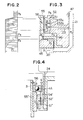
- Fig. 2 shows the hydrostatic lubricated bearing system 51 in detail, which is formed with orifices 53a and 53b in the hydrostatic lubricated pocket 52 and the bearing case 54. Meanwhile the inner casing 2 supporting the bearing case 54 is formed with a duct 23 branching from a discharge passage 21 to lead a portion of a liquid to flow therefrom to the orifices 53a and 53b. Thus the liquid flowing through the discharge passage 21 is partly introduced through the orifices 53a and 53b into the pocket portion of the hydrostatic lubricated pocket 52.
- a vertical duct 56 located inwardly of the rotary sleeve 55 maintains an intervening chamber 46 defined between a rotary ram 45 and the hydrostatic lubricated bearing system 51 in communication with a motor chamber 47 containing the stator 9 and the rotor 91 therein.
- the ball bearing 4A includes an outer race section 41A having a slide bearing 42A arranged therein (see Fig. 1) to allow the ball bearing 4A to smoothly follow up the vertical movement of the rotary shaft 3.
- the slide bearing 42A which functions on the same principle as a radial bearing mounted at a lowermost end of a pump section is operative to introduce a portion of a pressurized liquid into a branch duct 24 to feed same to the slide bearing 42A having a hydrostatic lubricated pocket to cover the outer race section 41A with a film of pressurized liquid, to thereby minimize resistance offered to the sliding movement to allow the outer race section 41A to quickly follow up the vertical movement of the rotary shaft 3.
- This is conductive to prevention of occurrence of abnormal phenomenons in the ball bearing 4A (inordinate wear or seizure caused by unbalanced movement or lopsided loading).
- motor startup causes the impeller 6 to begin to rotate to supply a liquid on the suction side to the piping by pressurizing same.
- a portion of the pressurized liquid flows through a gap in the rotary ram 45 of the load reducing system while pushing the ram 45 upwardly.
- the discharge passage 21 has connected midway thereto the branch duct 23, and the hydrostatic lubricated bearing system 51 according to the invention for applying a radial load is mounted as a bearing at the lower end of the motor section.
- pressurized liquid introduced into the branch duct 23 flows into the hydrostatic lubricated pocket 52 contained in the bearing case 54 of the hydrostatic lubricated bearing system 51, to apply a lubricating film of pressurized liquid to the pocket section to thereby support the rotary shaft 3 through the film of pressurized liquid.
- the embodiment of the invention of the aforesaid constructional form offers the following advantages.
- the service life of the bearing is greatly prolonged when the hydrostatic lubricated bearing system 51 is used as compared with the service life of an ordinary ball bearing that would be used in a conventional arrangement. Additionally any inordinate wear or seizure that might be caused by unbalanced movement or lopsided loading can be avoided.
- the vertical duct 56 is provided in a plurality of numbers inwardly of the sleeve 55 to maintain the intervening chamber 46 in communication with the motor chamber 47 in which low pressure prevails.
- a rise in the pressure in the intervening chamber 46 is avoided to enable the hydrostatic lubricated bearing system 51 and the rotary ram 45 to properly function.
- the pressure in the intervening chamber 46 drops as indicated by a broken line in Fig. 3, to enable an ideal pressure distribution to be obtained in various elements.
- This arrangement has the effect of the anti-thrust force Fa to be produced by the back pressure differential CP 1 - P 2 ) of the rotary ram 45 while giving rise to a radial reaction Fr in the hydrostatic lubricated bearing, so that a film of pressurized liquid is provided to the bearing surface to allow the rotary shaft 3 and the hydrostatic lubricated bearing system 51 to operate while being not in direct contact with each other.
- Fig. 4 shows another embodiment which is provided with a hydrostatic lubricated bearing system 51' of the same constructional form as that described by referring to the first embodiment shown in Figs. 1-3.
- the system 51' is located immediately below the ball bearing 4A, and a lower bearing on the motor side is the same hydrostatic lubricated bearing system as described by referring to the embodiment shown in Fig. 1.
- the reason why the ball bearing 4A and the hydrostatic lubricated bearing system 51' are used in combination as an upper bearing on the motor side in the embodiment shown in Fig. 4 is as follows. When a liquid much lower in viscosity than water is handled, it would be virtually impossible to bear the weight of a rotary member itself by a thrust bearing and a slide bearing when the equipment is started, so that the ball bearing 4A and the hydrostatic lubricated bearing system 51' are used in combination for bearing the weight of their own.
- a gap g between the outer race of the ball bearing 4A and the bearing case 54' is greater than a gap G between the hydrostatic lubricated pocket 52' and the rotary sleeve 55' of the hydrostatic lubricated bearing system 51' or g > G.
- the rotary shaft 3 which is unitary with the rotary ram 45 would gradually move upwardly by virtue of a pumping pressure, to become balanced in a flating clearance C of the rotary ram 45 shown in Fig. 1.
- the rotary shaft 3 is moved by its own weight only for a short period when the pump is started and brought to a halt, and almost no load is applied to the ball bearing 4A during steadystate operation because a thrust load is kept from being applied thereto by the load reducing system and a radial thrust is borne by the hydrostatic lubricated bearing system 51' in the upper portion of the shaft 3. Let us estimate the possible service life.
- the ball bearing and the hydrostatic lubricated bearing system have been described as being used in combination only as an upper bearing on the motor side. It is to be understood, however, that the same combination may be used as a lower bearing on the motor side as well. Needless to say, other applications than those described herein may come to mind for the combination of a ball bearing and the hydrostatic lubricated bearing system 51'.
- At least one of the upper and lower bearings on the motor side for journaling a rotary shaft in the upper and lower portions of rotor is constituted by a ball bearing, and the rotary shaft is journaled, besides being journaled by the ball bearing, by a hydrostatic lubricated bearing system for bearing a radial thrust during operation.
Abstract
Description
- This invention relates to vertical motor pumps, and more particularly it is concerned with a vertical motor pump suitable for use as an electric pump of a submerged type for pumping up a liquid of low viscosity, such as a cryogenic liquid.
- Generally, a vertical motor pump, such as a vertical submerged pump, which is equipment for handling a liquid of low viscosity, such as water, a cryogenic liquid, etc., has as its main bearings ball bearings formed of corrosion resistant metal.
- The ball bearings of this type are constructed such that they are lubricated by a liquid of low viscosity, so that they could not be expected to have a prolonged service life under high load as is the case with ball bearings of an oil lubricated type. Thus various measures have hitherto been taken to prolong their service life. A ball bearing usually comprises an inner race, an outer race and balls. They are all formed of corrosion resistant metal. When a ball bearing is intended for use with equipment in which lubrication with a liquid of low viscosity is inevitable, the following lubrication techniques are used. A cage is formed of special resinous material provided by reinforcing expensive tetrafluoroethylene resin with glass fibers and mixing a self-lubricating agent, such as molybdenum disulfide (MoS2) powder with the resin. When the cage of this type is used, the MOS2 is transferred to the balls and adheres thereto as the balls are brought into contact with the cage during operation, to thereby achieve lubrication. However, even if this system is used, it would be difficult to prolong the service life of the ball bearings as one might wish. Thus, attempts have been made to adopt a load reducing system which is intended to reduce a load applied to the bearings to prolong their service life. A vertical motor pump provided with this load reducing system comprises a casing plate placed on an upper flange of an outer casing, and an inner casing located at the casing plate. The inner casing has secured to its interior a stator including a stator core and a stator coil, and a rotor including a rotor core and a rotor coil is arranged in predetermined spaced relation to the stator, to provide a motor section. Pump members, such as an impeller, are located in a position below the motor section. The rotor of the motor section and the impeller or a pump member are connected together by a rotary shaft for rotation therewith. The rotary shaft is journaled at its motor end by two ball bearings located one above the other and at its pump end by a radial bearing located at a lower end of the rotary shaft. A thrust load reducing system in the form of a rotary ram referred to hereinabove is mounted midway between the motor section and the pump section, to keep a pump thrust generated during pump operation from being directly applied to the ball bearings as a load.
- Operation of the motor pump of the aforesaid construction of the prior art will be described. Energization of the stator starts the rotor so that the rotary shaft fitted to the rotor and the impeller attached to a lower portion of the rotary shaft begin to rotate. Rotation of the impeller causes a liquid on the suction side to flow into the impeller blades and has its pressure raised by the impeller arranged in a plurality of stage before flowing into a discharge passage extending behind the stator and reaching a channel from which it is transferred to an external conduit. In this process, lubrication of the bearings supporting the rotor is effected by the liquid having its pressure raised by the impeller. The lubrication of the ball bearings located one above the other on the motor side will first be described. A portion of the pressurized liquid flows into a gap in the rotary ram of the load reducing system from a chamber before the majority of the pressurized liquid flows into the discharge passage. At this time, an upwardly oriented thrust is produced in the rotary ram by the raised pressure of the liquid while a thrust is produced in the pump by the impeller back pressure. These two thrusts cancel each other out, thereby achieving the effect of reducing a load applied to the lower ball bearing. The liquid flowing out of the gap in the rotary ram is introduced into the lower ball bearing and flows into a gap between the stator and the rotor while lubricating the ball bearing, to effect cooling of portions heated by a current passed thereto. Then the liquid lubricates the ball bearing located at an upper end of the rotary shaft and gathers together in an overflow pipe before being returned to the suction side (in this case the liquid may flow through a heat exchanger before being returned to the suction side). Let us now study the behavior of the rotary ram during a transitional period of operation. When the pump is inoperative, it moves downwardly to a lowermost position due to the weight of the rotor. When the pump starts operation, the rotary ram is moved upwardly by the pressurized liquid and the rotary shaft fitted thereto begins to shift, and the upper and lower ball bearings also shift by following suit.
- The load reducing system thus has the effect of causing the upper and lower ball bearings to quickly follow up the vertical movement of the rotary shaft to avoid occurrence of abnormal conditions in the ball bearings (inordinate wear or seizure caused by unbalanced movement or lopsides loading), so that one is able to have a bright outlook with regard to prolongation of the service life of the ball bearings. However, one should not shut one's eyes to the fact that an increase in the capacity of pumps successively increases a load applied to the pumps. The load reducing system would be able to cope with an increase in the thrust applied to the pumps if its specifications were altered. However, if the equipment were high in head, the circumference of an inner chamber of an impeller housing might become unbalanced hydrodynamically, to thereby generate a force which would act as a radial thrust on the bearings. Production of this force is governed to a great extent by the degree of precision with which the impeller housing, flow regulating plate and impeller blades are fabricated, and the direction in which the force acts as a load is not constant. Thus it is impossible to absorb the force by the load reducing system. The result of this is that the lower ball bearing most susceptibel to a radial thrust would have its service life shortened.
- Generally, calculation of the service life of a ball bearing is done by using equation (1). To achieve a prolongation of the service life, it is considered effective either to minimize the value of P or increase the capacity of C in equation (1). However, the capacity of C would be decided upon when decisions are made on the model and dimensions, and a reduction in P would be the last available means for prolonging the service life. This last available means could not be used when it is impossible, as described hereinabove, to reduce the load. Thus it would be impossible to obtain a prolongation of the service life.

- where L: service lift.
- K: coefficient of lubrication.
- C: basic rated load.
- P: working load.
- This invention has been developed for the purpose of obviating the aforesaid disadvantages of the prior art. Accordingly, the invention has as its object the provision of a vertical motor pump capable of withstanding a load that might be applied radially thereto, thereby enabling a prolongation of its service life to be achieved.
- The outstanding characteristic of the invention is that at least one of an upper bearing and a lower bearing on the side of a motor for rotatingly journaling a rotary shaft in an upper portion and a lower portion respectively of a rotor is constituted by a ball bearing, and the rotary shaft is journaled, besides being journaled by the ball bearing, by a hydrostatic lubricated bearing system which bears a load applied radially to the rotary shaft during its operation.
-
- Fig. 1 is a sectional view of the vertical motor pump comprising one embodiment of the invention;
- Fig. 2 is a sectional view of one-half portion of the hydrostatic lubricated bearing system used in the embodiment of the invention shown in Fig. 1, showing its details;
- Fig. 3 is a diagrammatic representation of a pressure distribution in all the parts of the hydrostatic lubricated bearing system shown in Fig. 2; and
- Fig. 4 is a schematic sectional view of another embodiment of the invention, showing the upper bearing on the motor side.
- The invention will now be described in detail by referring to the embodiments shown in the accompanying drawings.
- Fig. 1 shows the construction of a submerged pump serving as an example of the vertical motor pump according to the invention. Referring to Fig. 1, an outer casing 1 includes a casing plate 11 placed on an upper flange, and an
inner casing 2 is attached to the casing plate 11. Secured in theinner casing 2 is astator 9 comprising a stator core and a stator winding which is spaced apart a predetermined distance from arotor 91 comprising a rotor core and a rotor winding, so that thestator 9 and therotor 91 constitute a motor section. An impeller 6 and other pump parts are located below the motor section. Therotor 91 of the motor section is connected to arotary shaft 3 together with the impeller 6, for rotation with therotary shaft 3. - In this embodiment, an upper bearing on the motor side is constituted by a ball bearing 4A for journaling the
rotary shaft 3, and a hydrostatic lubricated bearingsystem 51 is provided to serve as a lower bearing for journaling therotary shaft 3 which is intended to bear a load applied radially to therotary shaft 3 during its rotation. The hydrostaticlubricated bearing system 51 comprises a hydrostaticlubricated pocket 52 arranged in a manner to enclose arotary sleeve 55 mounted on a portion of an outer periphery of therotary shaft 3 with a predetermined clearance between therotary sleeve 55 and the hydrostaticlubricated pocket 52, and abearing case 54 secured to theinner casing 2 for containing the hydrostaticlubricated pocket 52 therein. The hydrostaticlubricated pocket 52 includes a pocket portion for forming a film of pressurized lubricating liquid on therotary sleeve 55 side. - Fig. 2 shows the hydrostatic
lubricated bearing system 51 in detail, which is formed withorifices lubricated pocket 52 and the bearingcase 54. Meanwhile theinner casing 2 supporting the bearingcase 54 is formed with aduct 23 branching from adischarge passage 21 to lead a portion of a liquid to flow therefrom to theorifices discharge passage 21 is partly introduced through theorifices lubricated pocket 52. Avertical duct 56 located inwardly of therotary sleeve 55 maintains an interveningchamber 46 defined between arotary ram 45 and the hydrostaticlubricated bearing system 51 in communication with amotor chamber 47 containing thestator 9 and therotor 91 therein. Theball bearing 4A includes an outer race section 41A having a slide bearing 42A arranged therein (see Fig. 1) to allow the ball bearing 4A to smoothly follow up the vertical movement of therotary shaft 3. Theslide bearing 42A which functions on the same principle as a radial bearing mounted at a lowermost end of a pump section is operative to introduce a portion of a pressurized liquid into abranch duct 24 to feed same to the slide bearing 42A having a hydrostatic lubricated pocket to cover the outer race section 41A with a film of pressurized liquid, to thereby minimize resistance offered to the sliding movement to allow the outer race section 41A to quickly follow up the vertical movement of therotary shaft 3. This is conductive to prevention of occurrence of abnormal phenomenons in the ball bearing 4A (inordinate wear or seizure caused by unbalanced movement or lopsided loading). - Operation of the embodiment of the aforesaid constructional form will be described. As in the prior art, motor startup causes the impeller 6 to begin to rotate to supply a liquid on the suction side to the piping by pressurizing same. A portion of the pressurized liquid flows through a gap in the
rotary ram 45 of the load reducing system while pushing theram 45 upwardly. Thedischarge passage 21 has connected midway thereto thebranch duct 23, and the hydrostaticlubricated bearing system 51 according to the invention for applying a radial load is mounted as a bearing at the lower end of the motor section. Thus the pressurized liquid introduced into thebranch duct 23 flows into the hydrostaticlubricated pocket 52 contained in the bearingcase 54 of the hydrostaticlubricated bearing system 51, to apply a lubricating film of pressurized liquid to the pocket section to thereby support therotary shaft 3 through the film of pressurized liquid. - The embodiment of the invention of the aforesaid constructional form offers the following advantages. In the case of equipment which is high in head, it is possible to withstand any radial thrust which might be applied to the bearing by a hydrodynamically unbalanced force exerted on the circumference of the inner chamber of the impeller housing because of the arrangement that the lower bearing on the motor side is constituted by the hydrostatic
lubricated bearing system 51. The service life of the bearing is greatly prolonged when the hydrostaticlubricated bearing system 51 is used as compared with the service life of an ordinary ball bearing that would be used in a conventional arrangement. Additionally any inordinate wear or seizure that might be caused by unbalanced movement or lopsided loading can be avoided. - Let us discuss pressure acting in the vicinity of the hydrostatic
lubricated bearing system 51. The liquid pressurized at the impeller 6 enters achamber 20 and the majority thereof flows into thedischarge passage 21. However, a portion of the pressurized liquid pushes therotary ram 45 upwardly at its boss surface as shown in Fig. 2 to develop an anti-thrust force Fa which can be expressed as Fa = A(P1 - P2) where A is the area of the boss of therotary ram 45. The hydrostaticlubricated bearing system 51 admits a portion of the pressurized liquid from thedischarge passage 21 through thebranch duct 23 which is fed to the hydrostaticlubricated pocket 52 to provide a film of pressurized liquid. Thus the liquid flowing out of the bearing surface is passed to opposite end faces of the bearing and then into the interveningchamber 46. When operatoin is started at this time, pressures from all quarters are sealed in the interveningchamber 46 and the pressure applied to the region extending from thechamber 20 to the hydrostaticlubricated pocket 52 becomes equal to a supply pressure Pl, as indicated by a pressure distribution shown in Fig. 3. If this situation occurs, there would be the risk that therotary ram 45 and the hydrostaticlubricated bearing system 51 would cease to function as they are intended to, making it impossible for the hydrostatic lubricated bearing system to accomplish the object. To avoid this risk, thevertical duct 56 is provided in a plurality of numbers inwardly of thesleeve 55 to maintain the interveningchamber 46 in communication with themotor chamber 47 in which low pressure prevails. Thus a rise in the pressure in the interveningchamber 46 is avoided to enable the hydrostaticlubricated bearing system 51 and therotary ram 45 to properly function. When thevertical ducts 56 are provided, the pressure in the interveningchamber 46 drops as indicated by a broken line in Fig. 3, to enable an ideal pressure distribution to be obtained in various elements. This arrangement has the effect of the anti-thrust force Fa to be produced by the back pressure differential CP1 - P2) of therotary ram 45 while giving rise to a radial reaction Fr in the hydrostatic lubricated bearing, so that a film of pressurized liquid is provided to the bearing surface to allow therotary shaft 3 and the hydrostaticlubricated bearing system 51 to operate while being not in direct contact with each other. This eliminates the risk of wear being caused on the hydrostatic lubricated bearing system by metal-to-metal contact and makes it possible to operate the equipment stably over a prolonged period of time. - Fig. 4 shows another embodiment which is provided with a hydrostatic lubricated bearing system 51' of the same constructional form as that described by referring to the first embodiment shown in Figs. 1-3. The system 51' is located immediately below the
ball bearing 4A, and a lower bearing on the motor side is the same hydrostatic lubricated bearing system as described by referring to the embodiment shown in Fig. 1. - The reason why the
ball bearing 4A and the hydrostatic lubricated bearing system 51' are used in combination as an upper bearing on the motor side in the embodiment shown in Fig. 4 is as follows. When a liquid much lower in viscosity than water is handled, it would be virtually impossible to bear the weight of a rotary member itself by a thrust bearing and a slide bearing when the equipment is started, so that theball bearing 4A and the hydrostatic lubricated bearing system 51' are used in combination for bearing the weight of their own. The feature of the embodiment shown in Fig. 4 is that a gap g between the outer race of theball bearing 4A and the bearing case 54' is greater than a gap G between the hydrostatic lubricated pocket 52' and the rotary sleeve 55' of the hydrostatic lubricated bearing system 51' or g > G. By this feature, any radial thrust that might be produced during operation could be borne by the hydrostatic lubricated braring system and would not be exerted on the ball bearing. Meanwhile the load reducing system cannot perform its function when the pump is inoperative because a discharge pressure of the pump is unavailable, so that therotary shaft 3 would be moved downwardly by its own weight and journaled by theball bearing 4A through aflange 56. As the pump is rendered operative, therotary shaft 3 which is unitary with therotary ram 45 would gradually move upwardly by virtue of a pumping pressure, to become balanced in a flating clearance C of therotary ram 45 shown in Fig. 1. Therotary shaft 3 is moved by its own weight only for a short period when the pump is started and brought to a halt, and almost no load is applied to theball bearing 4A during steadystate operation because a thrust load is kept from being applied thereto by the load reducing system and a radial thrust is borne by the hydrostatic lubricated bearing system 51' in the upper portion of theshaft 3. Let us estimate the possible service life. Assume that the working load P is reduced by half (maximum load at startup and stop), for example, from
- In the embodiment shown and described hereinabove, the ball bearing and the hydrostatic lubricated bearing system have been described as being used in combination only as an upper bearing on the motor side. It is to be understood, however, that the same combination may be used as a lower bearing on the motor side as well. Needless to say, other applications than those described herein may come to mind for the combination of a ball bearing and the hydrostatic lubricated bearing system 51'.
- In the vertical motor pump according to the invention described hereinabove, at least one of the upper and lower bearings on the motor side for journaling a rotary shaft in the upper and lower portions of rotor is constituted by a ball bearing, and the rotary shaft is journaled, besides being journaled by the ball bearing, by a hydrostatic lubricated bearing system for bearing a radial thrust during operation. By this arrangement, when a radial load is applied to the bearing, it is borne by the hydrostatic lubricated bearing system, so that the radial load can be satisfactorily borne. This is conductive to prolongation to a great extent of the service life of the bearing, and the bearing can be advantageously used with a vertical motor pump.
Claims (7)
Applications Claiming Priority (2)
| Application Number | Priority Date | Filing Date | Title |
|---|---|---|---|
| JP57075427A JPS58192997A (en) | 1982-05-07 | 1982-05-07 | Vertical motor pump |
| JP75427/82 | 1982-05-07 |
Publications (3)
| Publication Number | Publication Date |
|---|---|
| EP0094075A2 true EP0094075A2 (en) | 1983-11-16 |
| EP0094075A3 EP0094075A3 (en) | 1984-08-22 |
| EP0094075B1 EP0094075B1 (en) | 1988-08-31 |
Family
ID=13575895
Family Applications (1)
| Application Number | Title | Priority Date | Filing Date |
|---|---|---|---|
| EP83104548A Expired EP0094075B1 (en) | 1982-05-07 | 1983-05-09 | Bearings for the rotor shaft of a vertical motor pump assembly |
Country Status (4)
| Country | Link |
|---|---|
| US (1) | US4545741A (en) |
| EP (1) | EP0094075B1 (en) |
| JP (1) | JPS58192997A (en) |
| DE (1) | DE3377877D1 (en) |
Families Citing this family (28)
| Publication number | Priority date | Publication date | Assignee | Title |
|---|---|---|---|---|
| JPS60237194A (en) * | 1984-05-10 | 1985-11-26 | Hitachi Ltd | Vertical type motor pump |
| JPH0226215Y2 (en) * | 1984-12-07 | 1990-07-17 | ||
| JPS61226593A (en) * | 1985-03-29 | 1986-10-08 | Tokyo Gas Co Ltd | Vertical submergible pump |
| JPH07719Y2 (en) * | 1986-01-23 | 1995-01-11 | 三菱重工業株式会社 | pump |
| US4886430A (en) * | 1988-07-18 | 1989-12-12 | Westinghouse Electric Corp. | Canned pump having a high inertia flywheel |
| JPH0278910U (en) * | 1988-12-07 | 1990-06-18 | ||
| JPH0290306U (en) * | 1988-12-27 | 1990-07-18 | ||
| JPH0734236Y2 (en) * | 1989-04-21 | 1995-08-02 | 株式会社荏原製作所 | Rotating machines such as turbo pumps equipped with magnetic bearings |
| ES2104991T3 (en) * | 1992-04-14 | 1997-10-16 | Ebara Corp | BEARING DEVICE FOR USE IN A HERMETIC-TYPE MOTOR. |
| JPH0730396U (en) * | 1993-10-29 | 1995-06-06 | 日本カーター株式会社 | Shaft support device for multi-stage submerged pump |
| US5685701A (en) * | 1995-06-01 | 1997-11-11 | Metaullics Systems Co., L.P. | Bearing arrangement for molten aluminum pumps |
| JPH09275234A (en) * | 1996-04-02 | 1997-10-21 | Fanuc Ltd | Blower for gas laser |
| JPH09324791A (en) * | 1996-06-07 | 1997-12-16 | Ebara Corp | Submerged motor pump |
| US6012898A (en) * | 1996-06-07 | 2000-01-11 | Ebara Corporation | Submerged motor pump |
| KR100469930B1 (en) * | 1996-06-07 | 2005-05-27 | 가부시키가이샤 에바라 세이사꾸쇼 | Submersible Motor Pump |
| US6095766A (en) * | 1998-07-29 | 2000-08-01 | Brown; Albert W. | Fuel transfer pump |
| DE19931936C2 (en) * | 1999-07-08 | 2001-11-29 | Ds Technologie Werkzeugmaschb | Bearing arrangement for machine tool spindles |
| KR100680195B1 (en) * | 2003-03-31 | 2007-02-08 | 엘지전자 주식회사 | A water quality sensor of washing machine |
| JP4300088B2 (en) * | 2003-09-29 | 2009-07-22 | 日機装株式会社 | Submerged pump |
| JP4281614B2 (en) | 2004-05-10 | 2009-06-17 | 株式会社日立プラントテクノロジー | Pump device |
| JP4513419B2 (en) * | 2004-05-24 | 2010-07-28 | 株式会社日立プラントテクノロジー | Pump device |
| US8079833B2 (en) * | 2005-07-29 | 2011-12-20 | Ksb Aktiengesellschaft | Electric motor having a coaxially associated pump |
| FR2906580B1 (en) * | 2006-09-28 | 2009-01-09 | Snecma Sa | PUMP WITH ELECTRIC MOTOR IMMERED IN THE PUMP FLUID |
| FR2915535B1 (en) * | 2007-04-30 | 2009-07-24 | Snecma Sa | ROTATING MACHINE COMPRISING A PASSIVE AXIAL BALANCING SYSTEM |
| FR2932530B1 (en) * | 2008-06-17 | 2011-07-01 | Snecma | TURBOMACHINE HAVING A LONG-LIFE HOLDING SYSTEM |
| NO333696B1 (en) | 2010-12-17 | 2013-08-26 | Vetco Gray Scandinavia As | System and method for instantaneous hydrostatic operation of hydrodynamic axial bearings in a vertical fluid set-off module |
| CN105298824A (en) * | 2014-06-27 | 2016-02-03 | 安瑞科(廊坊)能源装备集成有限公司 | Liquefied natural gas (LNG) immersed pump system |
| KR102171452B1 (en) * | 2019-06-21 | 2020-10-29 | 엘지전자 주식회사 | Motor assembly and manufacturing method thereof |
Citations (5)
| Publication number | Priority date | Publication date | Assignee | Title |
|---|---|---|---|---|
| US2796027A (en) * | 1953-08-25 | 1957-06-18 | Allis Chalmers Mfg Co | Combined fluid pressure bearing and seal for apparatus utilizing a fluid |
| US3165365A (en) * | 1961-12-05 | 1965-01-12 | Bbc Brown Boveri & Cie | Bearing arrangement for vertical shafts |
| DE1815088A1 (en) * | 1968-12-17 | 1970-06-18 | Klein Schanzlin & Becker Ag | Axial thrust compensation in canned motor pumps |
| GB1351826A (en) * | 1971-11-29 | 1974-05-01 | Carter Co J C | Lubricating cooling and balancing of pump and motor units |
| EP0041438A1 (en) * | 1980-06-02 | 1981-12-09 | JEUMONT-SCHNEIDER Société anonyme dite: | Hydrodynamic auxiliary bearing in motor-driven pump |
Family Cites Families (9)
| Publication number | Priority date | Publication date | Assignee | Title |
|---|---|---|---|---|
| US3123338A (en) * | 1964-03-03 | Floating capsule for dental handpiece | ||
| FR1239017A (en) * | 1959-10-12 | 1960-08-19 | Cie Constr Gros Mat Electromec | Bearings for sealed blowers or pumps |
| US3143381A (en) * | 1960-06-13 | 1964-08-04 | Commissariat Energie Atomique | Fluid thrust bearing |
| GB1002919A (en) * | 1964-04-14 | 1965-09-02 | Rolls Royce | Bearing assembly |
| FR2032189A5 (en) * | 1969-02-21 | 1970-11-20 | Guinard Pompes | |
| DE1928784C3 (en) * | 1969-06-06 | 1980-05-08 | Linde Ag, 6200 Wiesbaden | Pressurized gas-lubricated radial bearing with a pressurized gas-guided bearing part arranged within a bearing shell, which forms the sliding surface |
| US3652186A (en) * | 1970-05-25 | 1972-03-28 | Carter Co J C | Pressure lubricated, cooled and thrust balanced pump and motor unit |
| JPS55142995A (en) * | 1979-04-23 | 1980-11-07 | Hitachi Ltd | Static pressure bearing for vertical shaft pump |
| JPS5710796A (en) * | 1980-06-25 | 1982-01-20 | Hitachi Ltd | Vertical axis pump |
-
1982
- 1982-05-07 JP JP57075427A patent/JPS58192997A/en active Granted
-
1983
- 1983-05-09 US US06/492,641 patent/US4545741A/en not_active Expired - Lifetime
- 1983-05-09 DE DE8383104548T patent/DE3377877D1/en not_active Expired
- 1983-05-09 EP EP83104548A patent/EP0094075B1/en not_active Expired
Patent Citations (5)
| Publication number | Priority date | Publication date | Assignee | Title |
|---|---|---|---|---|
| US2796027A (en) * | 1953-08-25 | 1957-06-18 | Allis Chalmers Mfg Co | Combined fluid pressure bearing and seal for apparatus utilizing a fluid |
| US3165365A (en) * | 1961-12-05 | 1965-01-12 | Bbc Brown Boveri & Cie | Bearing arrangement for vertical shafts |
| DE1815088A1 (en) * | 1968-12-17 | 1970-06-18 | Klein Schanzlin & Becker Ag | Axial thrust compensation in canned motor pumps |
| GB1351826A (en) * | 1971-11-29 | 1974-05-01 | Carter Co J C | Lubricating cooling and balancing of pump and motor units |
| EP0041438A1 (en) * | 1980-06-02 | 1981-12-09 | JEUMONT-SCHNEIDER Société anonyme dite: | Hydrodynamic auxiliary bearing in motor-driven pump |
Also Published As
| Publication number | Publication date |
|---|---|
| DE3377877D1 (en) | 1988-10-06 |
| EP0094075B1 (en) | 1988-08-31 |
| US4545741A (en) | 1985-10-08 |
| EP0094075A3 (en) | 1984-08-22 |
| JPS6345517B2 (en) | 1988-09-09 |
| JPS58192997A (en) | 1983-11-10 |
Similar Documents
| Publication | Publication Date | Title |
|---|---|---|
| EP0094075A2 (en) | Bearings for the rotor shaft of a vertical motor pump assembly | |
| US4363608A (en) | Thrust bearing arrangement | |
| US4990068A (en) | Unique grease lubricated ball bearing canned motor pump | |
| US3708215A (en) | Hybrid boost bearing assembly | |
| US3494291A (en) | Bearing assembly | |
| US5271676A (en) | Combination package tilt pad journal bearing/dual self equalizing thrust bearings, with hydrostatic lift provisions | |
| US2997960A (en) | Gear pump | |
| US4822240A (en) | Compressor thrust balancer | |
| EP0901574B1 (en) | Submerged motor pump | |
| US6012898A (en) | Submerged motor pump | |
| JP4089209B2 (en) | Double suction centrifugal pump | |
| EP3896288A1 (en) | Centrifugal pump for conveying a fluid | |
| US5005990A (en) | Pump bearing system | |
| JPS5920572A (en) | Water lubricated bearing for hydraulic turbine | |
| JP4423803B2 (en) | Horizontal shaft type pump | |
| EP0798466A2 (en) | High-temperature motor pump | |
| US5147179A (en) | Turbine pump with multistage venting of lubricating fluid flow | |
| US3692373A (en) | Slipper bearing lubrication and seal | |
| GB2074241A (en) | Multi-stage condensate pump | |
| EP3857072B1 (en) | A multistage pump with axial thrust optimization | |
| RU2768071C1 (en) | Journal bearing with forced lubrication | |
| JPH0521676Y2 (en) | ||
| US3158102A (en) | Cooling and sealing of rotary equipment | |
| US10634152B2 (en) | Multi-bearing design for shaft stabilization | |
| US3349999A (en) | Centrifugal compressor |
Legal Events
| Date | Code | Title | Description |
|---|---|---|---|
| PUAI | Public reference made under article 153(3) epc to a published international application that has entered the european phase |
Free format text: ORIGINAL CODE: 0009012 |
|
| AK | Designated contracting states |
Designated state(s): DE GB IT SE |
|
| PUAL | Search report despatched |
Free format text: ORIGINAL CODE: 0009013 |
|
| AK | Designated contracting states |
Designated state(s): DE GB IT SE |
|
| 17P | Request for examination filed |
Effective date: 19841217 |
|
| GRAA | (expected) grant |
Free format text: ORIGINAL CODE: 0009210 |
|
| AK | Designated contracting states |
Kind code of ref document: B1 Designated state(s): DE GB IT SE |
|
| REF | Corresponds to: |
Ref document number: 3377877 Country of ref document: DE Date of ref document: 19881006 |
|
| ITF | It: translation for a ep patent filed |
Owner name: MODIANO & ASSOCIATI S.R.L. |
|
| PLBE | No opposition filed within time limit |
Free format text: ORIGINAL CODE: 0009261 |
|
| STAA | Information on the status of an ep patent application or granted ep patent |
Free format text: STATUS: NO OPPOSITION FILED WITHIN TIME LIMIT |
|
| 26N | No opposition filed | ||
| ITTA | It: last paid annual fee | ||
| PGFP | Annual fee paid to national office [announced via postgrant information from national office to epo] |
Ref country code: DE Payment date: 19920724 Year of fee payment: 10 |
|
| PGFP | Annual fee paid to national office [announced via postgrant information from national office to epo] |
Ref country code: SE Payment date: 19930405 Year of fee payment: 11 |
|
| PGFP | Annual fee paid to national office [announced via postgrant information from national office to epo] |
Ref country code: GB Payment date: 19930429 Year of fee payment: 11 |
|
| PG25 | Lapsed in a contracting state [announced via postgrant information from national office to epo] |
Ref country code: GB Effective date: 19930509 |
|
| PG25 | Lapsed in a contracting state [announced via postgrant information from national office to epo] |
Ref country code: SE Effective date: 19930510 |
|
| GBPC | Gb: european patent ceased through non-payment of renewal fee |
Effective date: 19930509 |
|
| PG25 | Lapsed in a contracting state [announced via postgrant information from national office to epo] |
Ref country code: DE Effective date: 19940201 |
|
| EUG | Se: european patent has lapsed |
Ref document number: 83104548.9 Effective date: 19931210 |