EP0100593A2 - Improved time slot arrangements for local area network systems - Google Patents
Improved time slot arrangements for local area network systems Download PDFInfo
- Publication number
- EP0100593A2 EP0100593A2 EP83303443A EP83303443A EP0100593A2 EP 0100593 A2 EP0100593 A2 EP 0100593A2 EP 83303443 A EP83303443 A EP 83303443A EP 83303443 A EP83303443 A EP 83303443A EP 0100593 A2 EP0100593 A2 EP 0100593A2
- Authority
- EP
- European Patent Office
- Prior art keywords
- time slot
- communication medium
- data
- interface unit
- communication system
- Prior art date
- Legal status (The legal status is an assumption and is not a legal conclusion. Google has not performed a legal analysis and makes no representation as to the accuracy of the status listed.)
- Granted
Links
Images


Classifications
-
- H—ELECTRICITY
- H04—ELECTRIC COMMUNICATION TECHNIQUE
- H04L—TRANSMISSION OF DIGITAL INFORMATION, e.g. TELEGRAPHIC COMMUNICATION
- H04L12/00—Data switching networks
- H04L12/28—Data switching networks characterised by path configuration, e.g. LAN [Local Area Networks] or WAN [Wide Area Networks]
- H04L12/40—Bus networks
- H04L12/407—Bus networks with decentralised control
- H04L12/413—Bus networks with decentralised control with random access, e.g. carrier-sense multiple-access with collision detection (CSMA-CD)
Definitions
- the present invention relates to local area network systems for use with computer and office automation systems and is more particularly concerned with arrangements for defining time slots on the common communication medium which is operated on a time division multiplex basis.
- U.K. Patent 1,314,810 A typical example of time division multiplex operated systems is shown in U.K. Patent 1,314,810.
- each subscribers station connected thereto contains its own control and clocking system.
- a crystal controlled oscillator experiences drift of the order of one in 10 which, at a transmission bit rate of the order of 5.12M bits per second, gives a one bit drift in every six frames.
- the system clock is arranged to divide down the bit rate oscillator to produce common medium time slots and frames for the station.
- the multiplexing system used in such a local area network requires to pack the time slots as closely together as the delay between the most separated subscribers stations will allow, to efficiently use the common medium.
- a communication system comprising a common communication medium and a plurality of subscribers interface units each connected to the common medium and each interface unit includes a data transmission arrangement for transmitting data information signals onto the medium and a data reception arrangement for receiving data information signals from the medium, the medium being arranged to operate in accordance with a time division multiplex in which each time slot includes an active period for the transmission of a data burst of data information signals and a transit period and each interface unit includes internal timing arrangements and means for observing the timing of traffic burst on the highway and means for adjusting the internal timing arrangements so that the time slot timing cycle within the interface unit corresponds with that of the data on the highway.
- the data signals which may include speech, take any well known form, such as digital signals in Manchester code or analogue or digital modulated carrier, sometimes known as broadband, and the medium may be electrical cable, optic fibre or broadcast by electromagnetic, ultrasonic or infrared, by suitable system design.
- time slot marker adjustment occurs in accordance with the following:
- This arrangement achieves the near simultaneous occurence of time slot markers by all interface units be they busy or free, by each unit observing the timing of traffic burts on the highway and adjusting the internal timing time slot marker to occur in the time between data bursts of existing traffic (i.e. in the transit period of each time slot).
- a station intending to send a long burst of continous data at fill line rate must restrict the frequency and length of such burts so as to not corrupt speech channels unduly as these will discard the speech samples for the period of the long burst; data channels must store their data until their channel is again available.
- the long burst station can broadcast a message in its first time slot to warn multiplexed stations that their time slot will be 'grabbed', but this is not essential for synchronisation purposes.
- the embodiment of the invention uses a co-axial cable communication medium COCM which is terminated in its characteristic impedance CIA and CIB at each end.
- a co-axial cable communication medium COCM which is terminated in its characteristic impedance CIA and CIB at each end.
- Connected to the communication medium are a number of interface units I/FA, I/FB, I/FC, I/FD, I/FE, I/FF, I/FG and I/FX which match the various subscriber terminals of the local area network to the communication medium COCM.
- the communication medium is operated on a time division multiplex basis with 32 duplex channels operating at a nominal 5Mb/s rate. Each channel may consist of a 'go' slot and a 'return' slot. Alternatively the full time slot can be used alternately in the 'go' and 'return' direction using the structure of Fig. 2.
- a line of text can be contained in one simplex time slot of 448 bits.
- the terminals connected to the system will vary of course depending upon the requirements of the system.
- microprocessor based terminals such as MPT can be connected to the medium as can bulk data storage equipment MTE.
- digital telephones DTA and DTB allow for voice communiction in addition to the handling of computer based data.
- dedicated special purpose stations may be provided for (i) digital telephone conferencing, (ii) short code dialling, (iii) external connection to public or private communication networks ETE, (iv) voice recording, (v) network usage accounting and (vi) protocol conversion stations.
- the data processing stations may include (i) word processors, (ii) access units for a main frame computer system, (iii) line printers, (iv) facsimile equipment FE, (v) acoustic couplers for passing data over the public telephone network and (vi) bulk storage data bases DBE.
- Each equipment connected to the local area network is interfaced by its own dedicated interface unit which may be particularised to the equipment, from a network point of view, by the use of a discrete equipment address number.
- concentrators for similar or mixed terminal types may share special interfaces.
- the communication medium is operated on a time division multiplex basis and a typical set of parameters for the medium is shown below:
- Figure 2 shows a suggested structure of two packet types which.would fit into the time slot. These packets are an addressing packet and a traffic (data) packet. The addressing packet would be used for setting up a channel in the TDM frame; traffic packets would then be sent until the transaction was complete. Using the parameters proposed, the maximum data rate which can be carried in 1 time slot per frame is 150 Kbit/s.
- Time slots will be arranged to suit the traffic carried by the system, in the case of a system carrying speech and data a convenient choice is for a duplex time slot which provides for a group of speech samples (octets) in both directions.
- This same time slot can be used in a number of ways to carry data on a simplex, duplex or polling basis.
- speech may be handled on the well known TASSI basis where a simplex time slot is seized only during a speech burst.
- the communication medium may be a co-axial cable using line coding of the Manchester code type and the header in each slot may be used to provide bit phase synchronisation.
- Fig. 3 shows a block diagram of a speech station.
- the time slot processor TS area must perform the functions of maintaining time slot synchronism, achieving slot access by contention when commanded, and receipt and transmission of packets as required.
- the time slot processor will be under the control the station microprocessor. It will have sufficient power to transmit in one time slot per frame, but must listen in each time slot, compare the station address with the packet address and interrupt the microprocessor when they match.
- the system microprocessor SP performs the functions of status monitoring, implementing the station facilities and performing various housekeeping functions such as self-test and call logging.
- Supervisory tones have been the traditional method of prompting the user and of providing information on system status. If these are still required then they must be generated within the stations, possibly by using the computing power of the microprocessor to load tone patterns into the receive buffer for conversion to audio by the CODEC. If a suitable display is included in the telephone, then the need for supervisory tones is reduced.
- the time slot processor TS P is responsible for the generation of a time slot marker which defines each time slot for the interface unit. Recapping the system oprates on a distributed synchronisation process which means that:-
- the objective of any alignment algorithm is to adjust each interface terminal clock so that repeated adjustment of all clocks will result in all terminals maintaining synchronism in a stable fashion.
- Fig. 4 illustrates the alignment procedure. If the packet of data observed by a terminal lies between two time slot markers, then this terminal is synchonised and no adjustment is necessary. A terminal is slow if the start of the data received occurs earlier than the terminal time slot marker. To realign the terminal clock to the received data the clock is advanced. If the end of a packet is received later than the time slot marker, the terminal is fast and its clock should be retarded.
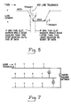
- Fig. 5 shows the time relationship between burts of data in time adjacent channels but from stations at opposite ends of a highway.
- the time slot comprises an active period for data or speech or contention resolution, followed by transit period in which the data reaches the opposite end of the highway.
- the time slot markers ideally occur simultaneously in both stations and for intermediate stations there is a tolerance which reaches maximum at the midway point.
- the first station to transmit will align the others immediately.
- the time slot markers indicate to the station circuity.
- Fig. 6 shows in block form the equipment required in the time slot processor TSP of Fig. 3.
- the equipment requires a traffic detector TD adapted to produce waveform A indicative of a busy time slot.
- the dotted lines referred ATS on waveform A indicate the effect of adjacent time slots if they were busy.
- the traffic present waveform A is applied to a logic block LB which is divided into two sections responsible for late detection LD and early detection ED.
- a waveform indicative of the local time slot from the local interface unit's timing generator TG.
- the local time slot is depicted in waveform B.
- three versions of waveform B are shown in Fig. 4 as BN, BL and BE indicating the three conditions which can occur (i.e. local time slot normal BN, local time slot late BL and local time slot early BE), in addition to zero traffic and continuous traffic.
- the local interface unit timing generator TG consists of a crystal controlled oscillator, operating at say 5.12 M Hz driving a divide-by-512 divider TS DIV to generate 100 u Second time slots.
- the divider TS DIV drives a divide-by-32 divider FDIV which is used to generate waveform C to define the time division multiplex frame of 3.2 milliseconds.
- This counter can be used to identify the time slot which has been seized by this interface unit when it is busy.
- the counter FDIV is controlled so that (a) it can count time slots when the interface unit is seeking or using a time slot and (b) it is reset if the unit is seeking a time slot and loses contention or the time slot is busy.
- the logic used in the late LD and early detection ED equipment will be realised as part of an integrated circuit chip although it could be standard logic or software on a microprocessor.
- the late detector operates (i.e. waveform BL) a signal is produced on lead T SL to drive the counter of the TS DIV to zero, as the local time slot has been adjuged late with respect to that on the communication medium.
- the early detector E D operates (i.e. waveform BE) it produces a signal on lead TSE to reset the TS DIV counter to zero if and when the traffic detector detects the traffic absent condition.
- the maximum data rate that can be transmitted over the common medium using one time slot per frame is 150 Kbit/s. This means that at the normal data circuit speeds (up to 9.6 Kbit/s) the system would operate inefficiently if one time slot were permanently allocated to one data circuit for the duration of the transfer. It can be seen that there is capacity for several data circuits to be multiplexed into one time slot. This would give a two-way benefit since the time slot could be used more efficiently and the per-port cost of several data connections could be reduced.
- the high speed data stations may be equipped, for instance, with capacity to seize up to five time slots in a frame, dependent on the required data speed and the number of empty time slots.
- a number of highways can be linked with gateway stations between each pair, providing multi-channel time slot shifting transfer between them.
- the physical location of the terminals of a system may be adapted to suit the circumstances.
- 'Go' and 'Return' wires may be provided with large amplification between to overcome attenuation when the common medium is on optical fibre link.
- a common amplifier with long leads in and out to the station could be provided.
Abstract
Description
- The present invention relates to local area network systems for use with computer and office automation systems and is more particularly concerned with arrangements for defining time slots on the common communication medium which is operated on a time division multiplex basis.
- A typical example of time division multiplex operated systems is shown in U.K. Patent 1,314,810. In such systems there is a common medium for communication and each subscribers station connected thereto contains its own control and clocking system. Typically a crystal controlled oscillator experiences drift of the order of one in 10 which, at a transmission bit rate of the order of 5.12M bits per second, gives a one bit drift in every six frames. The system clock is arranged to divide down the bit rate oscillator to produce common medium time slots and frames for the station. The multiplexing system used in such a local area network requires to pack the time slots as closely together as the delay between the most separated subscribers stations will allow, to efficiently use the common medium.
- It is an object of the present invention to achieve the above requirement.
- According to the invention there is provided a communication system comprising a common communication medium and a plurality of subscribers interface units each connected to the common medium and each interface unit includes a data transmission arrangement for transmitting data information signals onto the medium and a data reception arrangement for receiving data information signals from the medium, the medium being arranged to operate in accordance with a time division multiplex in which each time slot includes an active period for the transmission of a data burst of data information signals and a transit period and each interface unit includes internal timing arrangements and means for observing the timing of traffic burst on the highway and means for adjusting the internal timing arrangements so that the time slot timing cycle within the interface unit corresponds with that of the data on the highway.
- The data signals, which may include speech, take any well known form, such as digital signals in Manchester code or analogue or digital modulated carrier, sometimes known as broadband, and the medium may be electrical cable, optic fibre or broadcast by electromagnetic, ultrasonic or infrared, by suitable system design.
- The internal timing arrangements are arranged to produce a time slot marker which nominally occurs at the mid-point of the transit time of each time slot. Typically time slot marker adjustment occurs in accordance with the following:-

- This arrangement achieves the near simultaneous occurence of time slot markers by all interface units be they busy or free, by each unit observing the timing of traffic burts on the highway and adjusting the internal timing time slot marker to occur in the time between data bursts of existing traffic (i.e. in the transit period of each time slot).
- To accommodate long continuous bursts of data at maximum line rate occupying many time slots it is necessary to have an arrangement whereby the time slot marker arrangement is not corrupted. The above rules achieve this by making corrections dependent on discrete burts bounded by gaps, which continuous data will not have.
- A station intending to send a long burst of continous data at fill line rate must restrict the frequency and length of such burts so as to not corrupt speech channels unduly as these will discard the speech samples for the period of the long burst; data channels must store their data until their channel is again available.
- If required the long burst station can broadcast a message in its first time slot to warn multiplexed stations that their time slot will be 'grabbed', but this is not essential for synchronisation purposes.
- The invention will be more readily understood from the following description of one embodiment which should be read in conjunction with the accompanying drawings.
- Of the drawings:
- Fig. 1 shows in block form the system according to one embodiment of the invention.
- Fig. 2 shows suggested packet structures for the embodiment of the system.
- Fig. 3 shows a voice station interface unit block diagram.
- Fig. 4 shows waveform diagrams of the Alignment procedure.
- Fig. 5 shows waveform diagram of the time slot start positioning.
- Fig. 6 shows the logic and waveforms for time slot synchronisation, while
- Fig. 7 shows how a multi-common medium system may be implemented.
- The embodiment of the invention uses a co-axial cable communication medium COCM which is terminated in its characteristic impedance CIA and CIB at each end. Connected to the communication medium are a number of interface units I/FA, I/FB, I/FC, I/FD, I/FE, I/FF, I/FG and I/FX which match the various subscriber terminals of the local area network to the communication medium COCM. The communication medium is operated on a time division multiplex basis with 32 duplex channels operating at a nominal 5Mb/s rate. Each channel may consist of a 'go' slot and a 'return' slot. Alternatively the full time slot can be used alternately in the 'go' and 'return' direction using the structure of Fig. 2. A line of text can be contained in one simplex time slot of 448 bits. The terminals connected to the system will vary of course depending upon the requirements of the system. Typically microprocessor based terminals such as MPT can be connected to the medium as can bulk data storage equipment MTE. Similarly digital telephones DTA and DTB allow for voice communiction in addition to the handling of computer based data. In addition dedicated special purpose stations may be provided for (i) digital telephone conferencing, (ii) short code dialling, (iii) external connection to public or private communication networks ETE, (iv) voice recording, (v) network usage accounting and (vi) protocol conversion stations. Obviously the data processing stations may include (i) word processors, (ii) access units for a main frame computer system, (iii) line printers, (iv) facsimile equipment FE, (v) acoustic couplers for passing data over the public telephone network and (vi) bulk storage data bases DBE.
- Each equipment connected to the local area network is interfaced by its own dedicated interface unit which may be particularised to the equipment, from a network point of view, by the use of a discrete equipment address number. However, concentrators for similar or mixed terminal types may share special interfaces.
- As mentioned previously the communication medium is operated on a time division multiplex basis and a typical set of parameters for the medium is shown below:-

- Figure 2 shows a suggested structure of two packet types which.would fit into the time slot. These packets are an addressing packet and a traffic (data) packet. The addressing packet would be used for setting up a channel in the TDM frame; traffic packets would then be sent until the transaction was complete. Using the parameters proposed, the maximum data rate which can be carried in 1 time slot per frame is 150 Kbit/s.
- Time slots will be arranged to suit the traffic carried by the system, in the case of a system carrying speech and data a convenient choice is for a duplex time slot which provides for a group of speech samples (octets) in both directions.
- This same time slot can be used in a number of ways to carry data on a simplex, duplex or polling basis.
- To achieve greater throughput, speech may be handled on the well known TASSI basis where a simplex time slot is seized only during a speech burst.
- The communication medium may be a co-axial cable using line coding of the Manchester code type and the header in each slot may be used to provide bit phase synchronisation.
- The data stations (interface units) as mentioned previously interface the equipment to the communication medium. Fig. 3 shows a block diagram of a speech station.
- The time slot processor TS area must perform the functions of maintaining time slot synchronism, achieving slot access by contention when commanded, and receipt and transmission of packets as required. The time slot processor will be under the control the station microprocessor. It will have sufficient power to transmit in one time slot per frame, but must listen in each time slot, compare the station address with the packet address and interrupt the microprocessor when they match.
- The system microprocessor SP performs the functions of status monitoring, implementing the station facilities and performing various housekeeping functions such as self-test and call logging.
- Supervisory tones have been the traditional method of prompting the user and of providing information on system status. If these are still required then they must be generated within the stations, possibly by using the computing power of the microprocessor to load tone patterns into the receive buffer for conversion to audio by the CODEC. If a suitable display is included in the telephone, then the need for supervisory tones is reduced.
- The time slot processor TSP is responsible for the generation of a time slot marker which defines each time slot for the interface unit. Recapping the system oprates on a distributed synchronisation process which means that:-
- (1) There is no master clock.
- (2) Each interface terminal has a crystal controlled clock, but small variations of frequency from the nominal cause the terminal clocks to drift apart; some are fast and some are slow.
- (3) Due to propogation delay, a 100 us burst of data transmitted by any one interface terminal is received at different times by all other interface terminals.
- (4) To synchronise, each interface terminal is required to adjust its clock so as to align in time with the start or end of the packet of data it observes.
- (5) Between busy slots ech terminal drifts and is synchronised by the transmitter who uses the next busy slot.
- The objective of any alignment algorithm is to adjust each interface terminal clock so that repeated adjustment of all clocks will result in all terminals maintaining synchronism in a stable fashion.
- Fig. 4 illustrates the alignment procedure. If the packet of data observed by a terminal lies between two time slot markers, then this terminal is synchonised and no adjustment is necessary. A terminal is slow if the start of the data received occurs earlier than the terminal time slot marker. To realign the terminal clock to the received data the clock is advanced. If the end of a packet is received later than the time slot marker, the terminal is fast and its clock should be retarded.
- Fig. 5 shows the time relationship between burts of data in time adjacent channels but from stations at opposite ends of a highway. The time slot comprises an active period for data or speech or contention resolution, followed by transit period in which the data reaches the opposite end of the highway.
- The time slot markers ideally occur simultaneously in both stations and for intermediate stations there is a tolerance which reaches maximum at the midway point.
- This near simultaneous occurrence of time slot markers is maintained by all stations whether busy or free, observing the timing of traffic burts on the highway and adjusting the timing of their time slot marker to occur in the time between data bursts of existing traffic.
- Thus it can be seen that all stations are prepared to send traffic with the corrent timing.
- In the total absence of traffic, or when the system is started up, the first station to transmit will align the others immediately.
- Summing up, the simple rules for time slot marker adjustment are as follows:-

- The time slot markers indicate to the station circuity.
- (1) In the case of an established multiplex call, when to start transmitting data or busy signal, in conjunction with the appropriate channel signal from the frame marker.
- (2) In the case of searching for a free time slot, the beginning of the period of zero signal after which the time slot is considered free.
- Fig. 6 shows in block form the equipment required in the time slot processor TSP of Fig. 3. The equipment requires a traffic detector TD adapted to produce waveform A indicative of a busy time slot. The dotted lines referred ATS on waveform A indicate the effect of adjacent time slots if they were busy. The traffic present waveform A is applied to a logic block LB which is divided into two sections responsible for late detection LD and early detection ED. Also fed to the logic block LB is a waveform indicative of the local time slot from the local interface unit's timing generator TG. The local time slot is depicted in waveform B. In fact three versions of waveform B are shown in Fig. 4 as BN, BL and BE indicating the three conditions which can occur (i.e. local time slot normal BN, local time slot late BL and local time slot early BE), in addition to zero traffic and continuous traffic.
- The local interface unit timing generator TG consists of a crystal controlled oscillator, operating at say 5.12 M Hz driving a divide-by-512 divider TS DIV to generate 100 u Second time slots. The divider TS DIV drives a divide-by-32 divider FDIV which is used to generate waveform C to define the time division multiplex frame of 3.2 milliseconds. This counter can be used to identify the time slot which has been seized by this interface unit when it is busy. The counter FDIV is controlled so that (a) it can count time slots when the interface unit is seeking or using a time slot and (b) it is reset if the unit is seeking a time slot and loses contention or the time slot is busy. The logic used in the late LD and early detection ED equipment will be realised as part of an integrated circuit chip although it could be standard logic or software on a microprocessor. When the late detector operates (i.e. waveform BL) a signal is produced on lead TSL to drive the counter of the TS DIV to zero, as the local time slot has been adjuged late with respect to that on the communication medium. When the early detector ED operates (i.e. waveform BE) it produces a signal on lead TSE to reset the TS DIV counter to zero if and when the traffic detector detects the traffic absent condition.
- The above has indicated how the common medium can be operated on a time division multiplex basis which is so essential for devices which require to operate in a synchronous mode (for example speech). However, it is necessry for a local area network to be adapted to allow other modes of operation. One such mode of operation involves so-called 'system grab'. System grab requires that a long continuous burst of data at maximum line rate occupying many time slots can be transmitted.
- While correcting synchronisation depends on discrete time slot length burts of traffic, during continuous zero traffic or system grab traffic previous timing is maintained, with a drift due to crystal variations of about 1 bit in 6 frames.
- On resumption of normal slotted traffic this drift is corrected instantly.
- During a single frame's loss, speech stations will have to introduce 3.2 milliseconds of quiet in their audio path; at most, the user would notice a single click. The loss of access to one frame is normally even less severe for data stations since the traffic they are carrying will simply be held up for an extra 3.2 milliseconds.
- The maximum data rate that can be transmitted over the common medium using one time slot per frame is 150 Kbit/s. This means that at the normal data circuit speeds (up to 9.6 Kbit/s) the system would operate inefficiently if one time slot were permanently allocated to one data circuit for the duration of the transfer. It can be seen that there is capacity for several data circuits to be multiplexed into one time slot. This would give a two-way benefit since the time slot could be used more efficiently and the per-port cost of several data connections could be reduced.
- When considering the transfer of larger blocks of data, for instance, programs from floppy disc - across the common medium, then the data rate capacity is well suited to this. A 64 Kbyte program would be transferred in under 4 seconds, a 512 x 256 dot graphics image could be transferred to a screen in under one second.
- It is possible, however, to pass data along the commod medium faster than 150 Kbit/s; it can be sent at rates up to the burst data rate of 5 Mbit/s.
- The high speed data stations may be equipped, for instance, with capacity to seize up to five time slots in a frame, dependent on the required data speed and the number of empty time slots.
- A number of highways can be linked with gateway stations between each pair, providing multi-channel time slot shifting transfer between them.
- This greatly increases the traffic and terminal capacity of the system.
- The physical location of the terminals of a system may be adapted to suit the circumstances. For example 'Go' and 'Return' wires may be provided with large amplification between to overcome attenuation when the common medium is on optical fibre link. Alternatively a common amplifier with long leads in and out to the station could be provided.
Claims (14)
Priority Applications (1)
| Application Number | Priority Date | Filing Date | Title |
|---|---|---|---|
| AT83303443T ATE40247T1 (en) | 1982-08-04 | 1983-06-15 | TIME SLOT ARRANGEMENTS FOR LOCAL NETWORK SYSTEMS. |
Applications Claiming Priority (2)
| Application Number | Priority Date | Filing Date | Title |
|---|---|---|---|
| GB8222529 | 1982-08-04 | ||
| GB08222529A GB2125653B (en) | 1982-08-04 | 1982-08-04 | Improved time slot arrangements for local area network systems |
Publications (3)
| Publication Number | Publication Date |
|---|---|
| EP0100593A2 true EP0100593A2 (en) | 1984-02-15 |
| EP0100593A3 EP0100593A3 (en) | 1985-12-04 |
| EP0100593B1 EP0100593B1 (en) | 1989-01-18 |
Family
ID=10532112
Family Applications (1)
| Application Number | Title | Priority Date | Filing Date |
|---|---|---|---|
| EP83303443A Expired EP0100593B1 (en) | 1982-08-04 | 1983-06-15 | Improved time slot arrangements for local area network systems |
Country Status (13)
| Country | Link |
|---|---|
| US (1) | US4697263A (en) |
| EP (1) | EP0100593B1 (en) |
| JP (1) | JPS5944149A (en) |
| AT (1) | ATE40247T1 (en) |
| AU (1) | AU561905B2 (en) |
| CA (1) | CA1204231A (en) |
| DE (1) | DE3379018D1 (en) |
| DK (1) | DK162677C (en) |
| GB (1) | GB2125653B (en) |
| IE (1) | IE54630B1 (en) |
| NO (1) | NO167349C (en) |
| NZ (1) | NZ205124A (en) |
| ZA (1) | ZA834247B (en) |
Cited By (4)
| Publication number | Priority date | Publication date | Assignee | Title |
|---|---|---|---|---|
| US5495508A (en) * | 1987-11-20 | 1996-02-27 | Interdigital Technology Corporation | Base station emulator |
| US5544153A (en) * | 1992-04-16 | 1996-08-06 | Marttinen; Tapio | Method for transmission of digital information |
| US5930297A (en) * | 1989-11-20 | 1999-07-27 | Interdigital Technology Corporation | Base station emulator |
| US6711223B2 (en) | 1987-11-20 | 2004-03-23 | Interdigital Technology Corporation | Base station emulator |
Families Citing this family (22)
| Publication number | Priority date | Publication date | Assignee | Title |
|---|---|---|---|---|
| US4675863A (en) | 1985-03-20 | 1987-06-23 | International Mobile Machines Corp. | Subscriber RF telephone system for providing multiple speech and/or data signals simultaneously over either a single or a plurality of RF channels |
| CA1290020C (en) * | 1987-02-09 | 1991-10-01 | Steven Messenger | Wireless local area network |
| CA1332627C (en) * | 1987-03-17 | 1994-10-18 | Antonio Cantoni | Jitter control in digital communications links |
| JPS6447200A (en) * | 1987-08-18 | 1989-02-21 | Toshiba Corp | Digital key telephone system |
| JPH01132246A (en) * | 1987-08-31 | 1989-05-24 | Toshiba Corp | Data transmission system able to eliminate deviation of traffic |
| GB8807050D0 (en) * | 1988-03-24 | 1988-04-27 | British Telecomm | Communication system |
| US5289465A (en) * | 1988-08-18 | 1994-02-22 | Bull S.A. | Method for data transmission over an internal bus of a workstation apparatus with an internal bus for implementing the method, and an adapter circuit for the internal bus |
| FR2637440B1 (en) * | 1988-08-18 | 1994-05-13 | Bull Sa | METHOD FOR TRANSMITTING DATA ON AN INTERNAL BUS OF A WORKSTATION, INTERNAL BUS DEVICE, ALLOWING THE IMPLEMENTATION OF THE METHOD, AND ADAPTATION CIRCUIT FOR THIS INTERNAL BUS |
| US5638375A (en) * | 1988-11-30 | 1997-06-10 | Motorola, Inc. | AGC isolation of information in TDMA systems |
| US5241541A (en) * | 1990-03-15 | 1993-08-31 | International Business Machines Corporation | Burst time division multiplex interface for integrated data link controller |
| US5359598A (en) * | 1990-06-22 | 1994-10-25 | Unisys Corporation | Voice server for digital communication network |
| US5305314A (en) * | 1992-06-19 | 1994-04-19 | Westinghouse Electric Corp. | Global load smoothing in a real time data imaging network system |
| AU1974795A (en) | 1994-03-03 | 1995-09-18 | Proxim, Inc. | Frequency hopping medium access control protocol |
| US6292508B1 (en) | 1994-03-03 | 2001-09-18 | Proxim, Inc. | Method and apparatus for managing power in a frequency hopping medium access control protocol |
| JP3417741B2 (en) * | 1995-10-06 | 2003-06-16 | 富士通株式会社 | Transaction control system |
| US5666358A (en) * | 1995-10-16 | 1997-09-09 | General Instrument Corporation Of Delaware | Method and apparatus for supporting TDMA operating over hybrid fiber coaxial (HFC) or other channels |
| USRE38619E1 (en) * | 1995-10-16 | 2004-10-12 | General Instrument Corporation | Method and apparatus for supporting TDMA operating over hybrid fiber coaxial (HFC) or other channels |
| US6748451B2 (en) | 1998-05-26 | 2004-06-08 | Dow Global Technologies Inc. | Distributed computing environment using real-time scheduling logic and time deterministic architecture |
| GB0022269D0 (en) * | 2000-09-12 | 2000-10-25 | Koninkl Philips Electronics Nv | Data transmission system |
| US20060155770A1 (en) * | 2004-11-11 | 2006-07-13 | Ipdev Co. | System and method for time-based allocation of unique transaction identifiers in a multi-server system |
| US20060155753A1 (en) * | 2004-11-11 | 2006-07-13 | Marc Asher | Global asynchronous serialized transaction identifier |
| US20060123098A1 (en) * | 2004-11-11 | 2006-06-08 | Ipdev | Multi-system auto-failure web-based system with dynamic session recovery |
Citations (2)
| Publication number | Priority date | Publication date | Assignee | Title |
|---|---|---|---|---|
| US3641274A (en) * | 1968-10-11 | 1972-02-08 | Kokusai Denshin Denwa Co Ltd | Synchronization system for communication information in pcm time division multiple access communication system |
| US3668315A (en) * | 1970-05-15 | 1972-06-06 | Hughes Aircraft Co | Receiver timing and synchronization system |
Family Cites Families (17)
| Publication number | Priority date | Publication date | Assignee | Title |
|---|---|---|---|---|
| US3483330A (en) * | 1966-05-11 | 1969-12-09 | Bell Telephone Labor Inc | Network synchronization in a time division switching system |
| US3581010A (en) * | 1966-11-18 | 1971-05-25 | Fujitsu Ltd | Frame synchronization system for synchronizing the frame of a digital signal transmission |
| US3504126A (en) * | 1967-05-22 | 1970-03-31 | Bell Telephone Labor Inc | Network synchronization in a time division switching system |
| DE1904591B2 (en) * | 1969-01-30 | 1972-10-12 | Siemens AG, 1000 Berlin u. 8000 München | CIRCUIT ARRANGEMENT TO COMPENSATE FOR RUN TIME CHANGES DURING THE TRANSMISSION OF TIME MULTIPLEX MESSAGE SIGNALS, IN PARTICULAR FOR REMOTE INDICATION PCM SWITCHING SYSTEMS |
| GB1314180A (en) * | 1969-11-21 | 1973-04-18 | Plessey Telecommunications Res | Electrical data transmission systems |
| CH517419A (en) * | 1970-12-24 | 1971-12-31 | Ibm | Time division multiplex switch |
| US3846587A (en) * | 1972-02-22 | 1974-11-05 | Licentia Gmbh | Data transmission system for a multiple branch network |
| US3859465A (en) * | 1972-02-23 | 1975-01-07 | Licentia Gmbh | Data transmission system with multiple access for the connected users |
| GB1365838A (en) * | 1972-04-21 | 1974-09-04 | Ibm | Data handling system |
| US4156112A (en) * | 1977-12-07 | 1979-05-22 | Control Junctions, Inc. | Control system using time division multiplexing |
| US4199663A (en) * | 1978-11-06 | 1980-04-22 | The Boeing Company | Autonomous terminal data communications system |
| JPS5575361A (en) * | 1978-12-04 | 1980-06-06 | Oki Electric Ind Co Ltd | Time-division multi-direction multiple transmission system |
| FR2482806A1 (en) * | 1980-05-19 | 1981-11-20 | France Etat | METHOD AND DEVICE FOR SYNCHRONIZING A DIGITAL SIGNAL |
| US4509170A (en) * | 1982-02-22 | 1985-04-02 | Hydroacoustics Inc. | Time division multiplex transmission of submultiplex sequences of signals from sections of a chain of data acquisition units |
| US4464749A (en) * | 1982-02-24 | 1984-08-07 | General Electric Company | Bi-directional token flow system |
| US4404557A (en) * | 1982-03-05 | 1983-09-13 | Burroughs Corporation | Timed token ring with multiple priorities |
| JPS6124338A (en) * | 1984-07-12 | 1986-02-03 | Nec Corp | Multi-direction multiplex communication system |
-
1982
- 1982-08-04 GB GB08222529A patent/GB2125653B/en not_active Expired
-
1983
- 1983-06-07 AU AU15429/83A patent/AU561905B2/en not_active Ceased
- 1983-06-09 ZA ZA834247A patent/ZA834247B/en unknown
- 1983-06-15 AT AT83303443T patent/ATE40247T1/en not_active IP Right Cessation
- 1983-06-15 DE DE8383303443T patent/DE3379018D1/en not_active Expired
- 1983-06-15 EP EP83303443A patent/EP0100593B1/en not_active Expired
- 1983-06-28 CA CA000431307A patent/CA1204231A/en not_active Expired
- 1983-07-20 NO NO832638A patent/NO167349C/en unknown
- 1983-07-26 IE IE1753/83A patent/IE54630B1/en unknown
- 1983-07-29 US US06/518,476 patent/US4697263A/en not_active Expired - Fee Related
- 1983-08-03 NZ NZ205124A patent/NZ205124A/en unknown
- 1983-08-03 JP JP58142400A patent/JPS5944149A/en active Granted
- 1983-08-04 DK DK356683A patent/DK162677C/en active
Patent Citations (2)
| Publication number | Priority date | Publication date | Assignee | Title |
|---|---|---|---|---|
| US3641274A (en) * | 1968-10-11 | 1972-02-08 | Kokusai Denshin Denwa Co Ltd | Synchronization system for communication information in pcm time division multiple access communication system |
| US3668315A (en) * | 1970-05-15 | 1972-06-06 | Hughes Aircraft Co | Receiver timing and synchronization system |
Non-Patent Citations (1)
| Title |
|---|
| ELECTRONICS INTERNATIONAL, vol. 54, no. 12, June 1981, pages 176-181, New York, US; D. SCAVEZZE: "Nodes sound off to control access to local network" * |
Cited By (6)
| Publication number | Priority date | Publication date | Assignee | Title |
|---|---|---|---|---|
| US5495508A (en) * | 1987-11-20 | 1996-02-27 | Interdigital Technology Corporation | Base station emulator |
| US5625653A (en) * | 1987-11-20 | 1997-04-29 | Interdigital Technology Corporation | Base station emulator |
| US6711223B2 (en) | 1987-11-20 | 2004-03-23 | Interdigital Technology Corporation | Base station emulator |
| US7106819B1 (en) | 1987-11-20 | 2006-09-12 | Interdigital Technology Corporation | Plural subscriber system utilizing synchronized timeslots on a single frequency |
| US5930297A (en) * | 1989-11-20 | 1999-07-27 | Interdigital Technology Corporation | Base station emulator |
| US5544153A (en) * | 1992-04-16 | 1996-08-06 | Marttinen; Tapio | Method for transmission of digital information |
Also Published As
| Publication number | Publication date |
|---|---|
| IE54630B1 (en) | 1989-12-20 |
| NZ205124A (en) | 1986-09-10 |
| US4697263A (en) | 1987-09-29 |
| EP0100593B1 (en) | 1989-01-18 |
| CA1204231A (en) | 1986-05-06 |
| DK356683A (en) | 1984-02-05 |
| ATE40247T1 (en) | 1989-02-15 |
| DK162677B (en) | 1991-11-25 |
| NO167349C (en) | 1991-10-23 |
| EP0100593A3 (en) | 1985-12-04 |
| AU1542983A (en) | 1984-02-09 |
| JPH0311696B2 (en) | 1991-02-18 |
| JPS5944149A (en) | 1984-03-12 |
| ZA834247B (en) | 1984-03-28 |
| DK356683D0 (en) | 1983-08-04 |
| GB2125653B (en) | 1986-08-13 |
| AU561905B2 (en) | 1987-05-21 |
| GB2125653A (en) | 1984-03-07 |
| NO832638L (en) | 1984-02-06 |
| DK162677C (en) | 1992-04-13 |
| NO167349B (en) | 1991-07-15 |
| IE831753L (en) | 1984-02-04 |
| DE3379018D1 (en) | 1989-02-23 |
Similar Documents
| Publication | Publication Date | Title |
|---|---|---|
| US4697263A (en) | Time slot arrangements for local area network systems | |
| EP0596652B1 (en) | Network for transmitting isochronous-source data with a frame structure | |
| US6088362A (en) | Key telephone system without common control | |
| CA1168770A (en) | Idle time slot seizure and transmission facilities for loop communication system | |
| US4768188A (en) | Optical demand assigned local loop communication system | |
| JP2979319B2 (en) | Base station for wireless digital telephone system | |
| US5054020A (en) | Apparatus for high speed data communication with asynchronous/synchronous and synchronous/asynchronous data conversion | |
| JPS62241451A (en) | Line concentration and distribution system | |
| JPH03157032A (en) | Multichannel multipoint network obtained by using time-division multiplexing process | |
| JPH0630485B2 (en) | Time division bidirectional transmission method | |
| EP0334569B1 (en) | Method of and system for transmitting information | |
| US4556970A (en) | PBX Telephone system remote synchronization | |
| US6490294B1 (en) | Apparatus and method for interconnecting isochronous systems over packet-switched networks | |
| US6751232B1 (en) | Method and apparatus for communicating data between first and second pairs of transceivers communicating on a common communications link | |
| JP2745694B2 (en) | Bidirectional bus transmission system | |
| JP2641487B2 (en) | Simultaneous operation of multiple terminal devices | |
| EP0136749A1 (en) | Telephone exchange comprising peripheral control domains | |
| JP2001345773A (en) | Burst frame transmission system | |
| JPS63258130A (en) | Data transmission method | |
| JPH05347624A (en) | Inter-line equipment channel generating system | |
| JPH04246962A (en) | Specified terminal communication system | |
| JPS6162264A (en) | Frame synchronizing system | |
| JPH01194537A (en) | Synchronizing system for time division multiple transmitting device | |
| JPH04129340A (en) | Line changeover system | |
| JPS61181233A (en) | Frame synchronism system |
Legal Events
| Date | Code | Title | Description |
|---|---|---|---|
| PUAI | Public reference made under article 153(3) epc to a published international application that has entered the european phase |
Free format text: ORIGINAL CODE: 0009012 |
|
| AK | Designated contracting states |
Designated state(s): AT BE CH DE FR IT LI LU NL SE |
|
| 17P | Request for examination filed |
Effective date: 19840717 |
|
| PUAL | Search report despatched |
Free format text: ORIGINAL CODE: 0009013 |
|
| AK | Designated contracting states |
Designated state(s): AT BE CH DE FR IT LI LU NL SE |
|
| 17Q | First examination report despatched |
Effective date: 19870407 |
|
| GRAA | (expected) grant |
Free format text: ORIGINAL CODE: 0009210 |
|
| AK | Designated contracting states |
Kind code of ref document: B1 Designated state(s): AT BE CH DE FR IT LI LU NL SE |
|
| REF | Corresponds to: |
Ref document number: 40247 Country of ref document: AT Date of ref document: 19890215 Kind code of ref document: T |
|
| ITF | It: translation for a ep patent filed |
Owner name: ING. C. GREGORJ S.P.A. |
|
| REF | Corresponds to: |
Ref document number: 3379018 Country of ref document: DE Date of ref document: 19890223 |
|
| ET | Fr: translation filed | ||
| PLBE | No opposition filed within time limit |
Free format text: ORIGINAL CODE: 0009261 |
|
| STAA | Information on the status of an ep patent application or granted ep patent |
Free format text: STATUS: NO OPPOSITION FILED WITHIN TIME LIMIT |
|
| 26N | No opposition filed | ||
| ITTA | It: last paid annual fee | ||
| ITPR | It: changes in ownership of a european patent |
Owner name: CESSIONE;PLESSEY SEMICONDUCTORS LIMITED |
|
| REG | Reference to a national code |
Ref country code: CH Ref legal event code: PUE Owner name: PLESSEY SEMICONDUCTORS LIMITED |
|
| REG | Reference to a national code |
Ref country code: FR Ref legal event code: TP |
|
| PGFP | Annual fee paid to national office [announced via postgrant information from national office to epo] |
Ref country code: CH Payment date: 19930614 Year of fee payment: 11 Ref country code: AT Payment date: 19930614 Year of fee payment: 11 |
|
| PGFP | Annual fee paid to national office [announced via postgrant information from national office to epo] |
Ref country code: LU Payment date: 19930719 Year of fee payment: 11 |
|
| EPTA | Lu: last paid annual fee | ||
| PG25 | Lapsed in a contracting state [announced via postgrant information from national office to epo] |
Ref country code: LU Free format text: LAPSE BECAUSE OF NON-PAYMENT OF DUE FEES Effective date: 19940615 Ref country code: AT Effective date: 19940615 |
|
| PG25 | Lapsed in a contracting state [announced via postgrant information from national office to epo] |
Ref country code: LI Effective date: 19940630 Ref country code: CH Effective date: 19940630 |
|
| EAL | Se: european patent in force in sweden |
Ref document number: 83303443.2 |
|
| REG | Reference to a national code |
Ref country code: CH Ref legal event code: PL |
|
| PGFP | Annual fee paid to national office [announced via postgrant information from national office to epo] |
Ref country code: DE Payment date: 19950607 Year of fee payment: 13 |
|
| PGFP | Annual fee paid to national office [announced via postgrant information from national office to epo] |
Ref country code: FR Payment date: 19950609 Year of fee payment: 13 |
|
| PGFP | Annual fee paid to national office [announced via postgrant information from national office to epo] |
Ref country code: SE Payment date: 19950615 Year of fee payment: 13 |
|
| PGFP | Annual fee paid to national office [announced via postgrant information from national office to epo] |
Ref country code: NL Payment date: 19950628 Year of fee payment: 13 |
|
| PGFP | Annual fee paid to national office [announced via postgrant information from national office to epo] |
Ref country code: BE Payment date: 19950809 Year of fee payment: 13 |
|
| PG25 | Lapsed in a contracting state [announced via postgrant information from national office to epo] |
Ref country code: SE Effective date: 19960616 |
|
| PG25 | Lapsed in a contracting state [announced via postgrant information from national office to epo] |
Ref country code: BE Effective date: 19960630 |
|
| BERE | Be: lapsed |
Owner name: PLESSEY SEMICONDUCTORS LTD Effective date: 19960630 |
|
| PG25 | Lapsed in a contracting state [announced via postgrant information from national office to epo] |
Ref country code: NL Effective date: 19970101 |
|
| PG25 | Lapsed in a contracting state [announced via postgrant information from national office to epo] |
Ref country code: FR Effective date: 19970228 |
|
| PG25 | Lapsed in a contracting state [announced via postgrant information from national office to epo] |
Ref country code: DE Effective date: 19970301 |
|
| EUG | Se: european patent has lapsed |
Ref document number: 83303443.2 |
|
| NLV4 | Nl: lapsed or anulled due to non-payment of the annual fee |
Effective date: 19970101 |
|
| REG | Reference to a national code |
Ref country code: FR Ref legal event code: ST |