EP0100931A1 - Oscillation compensating apparatus for vortex flow meter - Google Patents
Oscillation compensating apparatus for vortex flow meter Download PDFInfo
- Publication number
- EP0100931A1 EP0100931A1 EP83107079A EP83107079A EP0100931A1 EP 0100931 A1 EP0100931 A1 EP 0100931A1 EP 83107079 A EP83107079 A EP 83107079A EP 83107079 A EP83107079 A EP 83107079A EP 0100931 A1 EP0100931 A1 EP 0100931A1
- Authority
- EP
- European Patent Office
- Prior art keywords
- oscillation
- compensating apparatus
- sensor
- piezoelectric
- shedding
- Prior art date
- Legal status (The legal status is an assumption and is not a legal conclusion. Google has not performed a legal analysis and makes no representation as to the accuracy of the status listed.)
- Granted
Links
Images


Classifications
-
- G—PHYSICS
- G01—MEASURING; TESTING
- G01F—MEASURING VOLUME, VOLUME FLOW, MASS FLOW OR LIQUID LEVEL; METERING BY VOLUME
- G01F1/00—Measuring the volume flow or mass flow of fluid or fluent solid material wherein the fluid passes through a meter in a continuous flow
- G01F1/05—Measuring the volume flow or mass flow of fluid or fluent solid material wherein the fluid passes through a meter in a continuous flow by using mechanical effects
- G01F1/20—Measuring the volume flow or mass flow of fluid or fluent solid material wherein the fluid passes through a meter in a continuous flow by using mechanical effects by detection of dynamic effects of the flow
- G01F1/32—Measuring the volume flow or mass flow of fluid or fluent solid material wherein the fluid passes through a meter in a continuous flow by using mechanical effects by detection of dynamic effects of the flow using swirl flowmeters
- G01F1/325—Means for detecting quantities used as proxy variables for swirl
- G01F1/3259—Means for detecting quantities used as proxy variables for swirl for detecting fluid pressure oscillations
- G01F1/3266—Means for detecting quantities used as proxy variables for swirl for detecting fluid pressure oscillations by sensing mechanical vibrations
-
- G—PHYSICS
- G01—MEASURING; TESTING
- G01F—MEASURING VOLUME, VOLUME FLOW, MASS FLOW OR LIQUID LEVEL; METERING BY VOLUME
- G01F1/00—Measuring the volume flow or mass flow of fluid or fluent solid material wherein the fluid passes through a meter in a continuous flow
- G01F1/05—Measuring the volume flow or mass flow of fluid or fluent solid material wherein the fluid passes through a meter in a continuous flow by using mechanical effects
- G01F1/20—Measuring the volume flow or mass flow of fluid or fluent solid material wherein the fluid passes through a meter in a continuous flow by using mechanical effects by detection of dynamic effects of the flow
- G01F1/32—Measuring the volume flow or mass flow of fluid or fluent solid material wherein the fluid passes through a meter in a continuous flow by using mechanical effects by detection of dynamic effects of the flow using swirl flowmeters
- G01F1/325—Means for detecting quantities used as proxy variables for swirl
-
- Y—GENERAL TAGGING OF NEW TECHNOLOGICAL DEVELOPMENTS; GENERAL TAGGING OF CROSS-SECTIONAL TECHNOLOGIES SPANNING OVER SEVERAL SECTIONS OF THE IPC; TECHNICAL SUBJECTS COVERED BY FORMER USPC CROSS-REFERENCE ART COLLECTIONS [XRACs] AND DIGESTS
- Y10—TECHNICAL SUBJECTS COVERED BY FORMER USPC
- Y10S—TECHNICAL SUBJECTS COVERED BY FORMER USPC CROSS-REFERENCE ART COLLECTIONS [XRACs] AND DIGESTS
- Y10S73/00—Measuring and testing
- Y10S73/04—Piezoelectric
Definitions
- the present invention relates to an oscillation compensating apparatus for a vortex flow meter.
- a vortex flow meter which includes a vortex shedding member disposed in a fluid passage or conduit.
- an instantaneous flow rate of a fluid flowing through the conduit is measured in terms of frequency of oscillations of the vortex shedding member which results from the Karman vortex street, or vortex train, shed in the conduit downstream of the vortex shedding member.
- Sources of the externally derived oscillations include a pump for compressing the fluid and a damper which is mechanically opened and closed. Implementations for solving this problem are disclosed in Japanese Utility Model Laid-Open Publication Nos. 57-19465/1982 and 57-28370/1982 for example, which are characterized by the use of two oscillation sensors.
- the output of one of the two sensors is employed to automatically control the triggering level of a Schmitt trigger or, alternatively, the outputs of both sensors are combined with each other.
- Such implementations are not fully acceptable from the viewpoint of their applicable flow rate range, because the two sensors located at different positions which make noise signals picked up thereby different in waveform or because strict adjustment is required in positioning the sensors.
- an oscillation compensating apparatus for removing externally derived oscillation noise applied to the flow meter of the present invention includes an elongate vortex shedding member extending into the conduit through part of a wall of the conduit.
- the vortex shedding member has a shedding portion constituted by a portion thereof located inside the conduit and a compensating portion constituted by a portion thereof located outside the conduit.
- First oscillation sensor means is disposed in the shedding portion for sensing an oscillation component caused in the shedding portion by a vortex train and the externally derived oscillation noise, and outputs a first signal having a frequency which corresponds to the oscillation and noise components.
- Second oscillation sensor means is disposed in the compensating portion for sensing only the noise component and outputs a second signal having a frequency which corresponds to the noise component.
- oscillation compensating apparatus for a vortex flow meter of the present invention is susceptible of numerous physical embodiments, depending upon the environment and requirements of use, substantial numbers of the herein shown and described embodiments have been made, tested and used, and all have performed in an eminently satisfactory manner.
- FIG. 1 of the drawings there is shown a vortex flow meter furnished with a vibration compensating apparatus 10 embodying the present invention.
- An elongate vortex shedding member 12 extends into a conduit 14 through which a fluid 16 is allowed to flow.
- the vortex shedder 12 having a triangular cross-section for example, is rigidly mounted to the wall of the conduit 14 by means of screws 18 and 20.
- a bore 12a extends axially through the vortex shedder 12 from the top toward the bottom and accomodates thereinside a first oscillation sensor 22 inside of the conduit 14 and a second oscillation sensor 24 outside of the same.
- the first and second oscillation sensors 22 and 24 are rigidly confined together in the bore 12a by a glass envelope 26.
- a balance weight 28 is coupled over the vortex shedder 12 adjacent to the outermost end of the latter. The position of the balance weight 28 relative to the element 12 is controllable as desired by means of an adjusting screw 30.
- the first sensor 22 comprises a flat base plate 32 made of metal and extending substantially along the axis of the bore 12a, a pair of piezoelectric elements 34 and 36 rigidly mounted on opposite sides of the base plate 32, and metal electrodes 38 and 40 respectively deposited on the piezoelectric elements 34 and 36 as by evaporation or gold paste baking.
- the second sensor 24 comprises a pair of piezoelectric elements 42 and 44 individually fixed to opposite sides of the base plate 32, and metal electrodes 46 and 48 respectively deposited on the piezoelectric elements 42 and 44.
- a piezoelectric sensor 22a is formed by the base plate 32, piezoelectric element 34 and electrode 38 in the first sensor 22.
- piezoelectric sensor 22b which faces the sensor 22a, is formed by the base plate 32, piezoelectric element 36 and electrode 40.
- the second sensor 24 has a piezoelectric sensor 24a formed by the base plate 32, piezoelectric element 42 and electrode 46, and another piezoelectric sensor 24b formed by the base plate 32, piezoelectric element 44 and electrode 48, the piezoelectric sensors 24a and 24b being located to face each other.
- the first and second sensors 22 and 24 having the above construction are installed in the axial bore 12a of the vortex shedder 12 such that the electrodes 38 and 40 and the electrodes 46 and 48 face each other each in a direction perpendicular to the flow direction of the fluid 16 in the conduit 14.
- the electrodes 38 and 40 are located face-to-face in symmetrically with respect to the base plate 32 and so are the electrodes 46 and 48, as viewed from the upstream or downstream side with respect to the fluid flow.
- the glass envelope 26 retaining the sensors 22 and 24 inside the bore 12a functions in three ways: completely insulating the sensors from the surrounding elements, causing the sensors to oscillate in a unitary structure with the vortex shedder 12, and enhancing the resistivity of the sensors to heat. Therefore, so long as these functions are satisfied, the envelope 26 may be made of resin, ceramic or the like, instead of glass.
- FIG. 2 there are shown electrical connections of the sensor made up of the piezoelectric sensors 22a and 22b and the sensor made up of the piezoelectric sensors 24a and 24b, and a circuit arrangement for processing outputs of the two sensors to remove noise components therefrom.
- the output signals of the first and second sensors 22 and 24 are sequentially processed by a charge amplifier 50, a low-pass active filter 52 and a Schmitt trigger 54.
- a pulse signal appears at an output terminal 56.
- a vortex train is shed in a known manner in a position downstream of that part of the vortex shedder 12 located inside of the conduit 14 (this part will be referred to as the "shedding portion” hereinafter).
- the vortex train causes the shedding portion of the vortex shedder 12 to oscillate substantially perpendicular to the flow of the fluid through the conduit 14, that is, in the lateral direction as seen in Figure 1.
- the piezoelectric sensors 22a and 22b of the first sensor 22, which is integral with the vortex shedder 12 as mentioned earlier, sense the oscillations to deliver a signal proportional to the oscillation frequency.
- their output levels are added to each other.
- the problem is that the output signal of the first sensor 22 is entraining noise due to external oscillations which propagate through the conduit 14, in addition to the expected oscillations due to the vortex train.
- the piezoelectric sensors 22a and 22b of the first sensor 22 face each other in the direction perpendicular to the fluid flow, they are hardly sensitive to oscillations parallel to the fluid flow and, if sensitive, the resulting outputs would cancel each other to not constitute any noise due to the differential interconnection of the electrodes.
- it comes to externally derived oscillations of the conduit 14 perpendicular to the fluid flow and vortex shedder 12 they are allowed to reach the shedding portion of the shedder 12 to be detected together with the oscillations caused by the vortex train.
- the second sensor 24 is adapted to sense only the external oscillations which are transferred through the conduit 14.
- the vortex shedder 12 is firmly fastened to the conduit 14 by means of the screws 18 and 20 so that the oscillation of the shedding portion of the shedder 12 is prevented from propagating outwardly beyond the fastened position to the remaining outer portion of the shedder 12 (this portion will be referred to as the "compensating portion” hereinafter).
- the second sensor 24, therefore, is immune to oscillation except for those which are introduced into conduit 14 from the outside. It will be noted that the second sensor 24 is common to the first 22 in sensing only the oscillations in the direction perpendicular to the fluid flow and shedder 12.
- both the shedding and compensating portions of the shedder 12 bend to the left to a position indicated by a dash-and-dots line 12c. Therefore, the first and second sensors 22 and 24 translate an external oscillation into a same waveform. Concerning the second sensor 24, however, it senses the composite oscillations of oscillations due to external oscillations and oscillations due to the vortex train.
- the output of the second sensor 24 will cancel a noise component in the output of the first sensor 22 thereby leaving only the signal resulted from the vortex train.
- the sensors 22 and 24 are high impedance elements, their outputs are transformed into voltage variations by the charge amplifier 50.
- the low-pass active filter 52 removes from the voltage variations high frequency components which have no bearing on the oscillations of the vortex shedder 12.
- the Schmitt trigger 54 processes an output of the filter 52 into a rectangular pulse signal which accurately reflects an oscillation frequency provided by the vortex train only. Counting the output pusles of the Schmitt trigger 54 provides any instantaneous flow rate of the fluid 16.
- FIG 4 a modification to the sensor assembly of Figure 1 is illustrated.
- the same reference numerals as those of Figure 1 designate the same structural elements. While in Figure 1 the piezoelectric elements 34 and 36 of the first sensor 22 are physically independent of their adjacent counterparts 42 and 44 of the second sensor 24, in Figure 4 the adjacent piezoelectric elements are replaced by a pair of common piezoelectric elements 56 and 58.
- a terminal 60 is led out from the metal base plate 32; a terminal 62 is led out from the electrodes 38 and 40 which are respectively associated with the elements 56 and 58 of opposite polarities; and a terminal 64 is led out from the electrodes 46 and 48 which are respectively associated with the elements 56 and 58 of opposite polarities.
- FIG. 5 A circuit for processing outputs of the sensors 22 and 24 of Figure 4 is shown in Figure 5, in which the same reference numerals as those of Figure 2 designate the same structural elements.
- the circuit includes a charge amplifier 50a connected to the output terminals 60 and 62 of the first sensor 22, a second charge amplifier 50b connected to the output terminals 60 and 64 of the second oscillation sensor 24, a variable amplifier 66, and an adder or substractor 69.
- the circuit of Figure 5 will prove effective when the output level of the first sensor 22 differs from that of the second 24.
- the waveform of noise included in the output of the first sensor 22 is in principle the same as the waveform of the output of the second sensor 24 as already discussed, a difference sometimes develops between the two output levels due to a difference in amplitude or the like between the inner and outer portions of the shedder 12.
- the circuit of Figure 5 allows the output of the amplifier 66 and thereby that of the second sensor 24 to be adjusted such that the second sensor output reaches a same level as the first sensor output, which is provided through the charge amplifier 50a. Then, the first and second sensor outputs will be combined by the adder or substractor 66 to remove the noise component.
- the first sensor 22 shown in Figure 6 comprises a cylindrical metal tube 70, an annular piezoelectric element 72 mounted on the tube 70, and a pair of metal electrodes 74 and 76, which are individually deposited on the piezoelectric element 72 as by evaporation or gold paste baking in such a manner as to oppose each other.
- the second sensor 24 shares the metal tube 70 with the first sensor 22 and has, in addition thereto, an annular piezoelectric element 78 fit around the tube 70, and a pair of metal electrodes 80 and 82 deposited on the element 78 in the same manner as the electrodes 74 and 76.
- the tube 70, piezoelectric element 72 and electrode 74 constitute one piezoelectric sensor 22a in combination, while the tube 70, piezoelectric element 72 and electrode 76 constitute another piezoelectric sensor 22b which faces the piezoelectric sensor 22a.
- the tube 70 cooperates with the piezoelectric element 78 and electrode 80 to form one piezoelectric sensor 24a, while cooperating with the piezoelectric element 78 and electrode 82 to form another piezoelectric sensor 24b, which faces the piezoelectric sensor 24a.
- the orientation of the sensor assembly inside the element 12 is such that the electrodes 74 and 76 and the electrodes 80 and 82 face each other each in a direction perpendicular to the flow direction of the fluid 12 in the conduit 14.
- the electrodes 74 and 76 located face-to-face in the lateral direction and so are the electrodes 80 and 82, as seen from the upstream or downstream side with respect to the fluid flow.
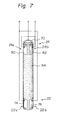
- FIG. 7 Shown in Figure 7 is a modification to the sensor assembly of Figure 6.
- a piezoelectric element 84 covers the whole outer periphery of the metal tube 70, in contrast to the spaced piezoelectric elements 72 and 78 of Figure 6.
- the electrodes 74 and 76 constituting the first sensor 22 are carried on one axial end of the piezoelectric element 84, while the metal electrodes 80 and 82 constituting the second sensor 24 are carried on the other axial end of the same.
- FIG 8. Still another modification to the cylindrical sensor configuration, particularly to that of Figure 6, is shown in Figure 8.
- a pair of spaced piezoelectric elements 72a and 72b are mounted on one end of the metal tube 70 and a pair of spaced piezoelectric elements 78a and 78b on the other end. That is, the piezoelectric element pair 72a-72b is a divided version of the piezoelectric element 72 of Figure 6 and the piezoelectric element pair 78a-78b, that of the piezoelectric element 78.
- circuits shown in Figures 2 and 5 are selectively usable for processing output signals of the cylindrical oscillation sensor assemblies shown in Figure 6-8, just as they are used for the others.
- an oscillation sensor using a piezoelectric element or the like has to have its electrode portions perfectly insulated from the surrounding members by means of glass or the like.
- This has heretofore been implemented by a method which fills the space concerned with glass powder and then heats the glass to melt and harden it, or a method which fills the space with a preformed glass.
- the problem encountered with the use of glass powder is that the filling and heating procedure has to be repeated several times because the volume of glass is smaller in the hardened state after heating than in the initial powdery state.
- the method using a preformed glass invites an increase in cost due to the intricate structure required therefor.
- any one of the cylindrical sensor configurations shown in Figures 6-8 will facilitate the procedure for fixing the sensors within the vortex shedding member 12.
- the present invention provides an oscillation compensating apparatus for a vortex flow meter which offers an excellent signal-to- noise ratio despite its simple and easy-to-produce structure.
- the sensors 22 and 24 may comprise physically separate members which are individually nested in the shedder 12, instead of the integral structure on a single base plate or a tube shown and described.
Abstract
Description
- The present invention relates to an oscillation compensating apparatus for a vortex flow meter.
- One approach to the measurement of a flow rate of a fluid is, as well known in the art, a vortex flow meter which includes a vortex shedding member disposed in a fluid passage or conduit. With this type of flow meter, an instantaneous flow rate of a fluid flowing through the conduit is measured in terms of frequency of oscillations of the vortex shedding member which results from the Karman vortex street, or vortex train, shed in the conduit downstream of the vortex shedding member.
- A problem has existed in the vortex flow meter in that a sensor thereof sensitive to the oscillations of the vortex shedding member, or shedder, picks up not only oscillations due to the vortex train but various kinds of externally derived oscillations, thereby making accurate flow rate measurement difficult. Sources of the externally derived oscillations include a pump for compressing the fluid and a damper which is mechanically opened and closed. Implementations for solving this problem are disclosed in Japanese Utility Model Laid-Open Publication Nos. 57-19465/1982 and 57-28370/1982 for example, which are characterized by the use of two oscillation sensors. The output of one of the two sensors is employed to automatically control the triggering level of a Schmitt trigger or, alternatively, the outputs of both sensors are combined with each other. However, such implementations are not fully acceptable from the viewpoint of their applicable flow rate range, because the two sensors located at different positions which make noise signals picked up thereby different in waveform or because strict adjustment is required in positioning the sensors.
- It is therefore an object of the present invention to provide an oscillation compensating apparatus for a vortex flow meter which effectively eliminates oscillation noise propagating through a conduit to pick up only expected oscillations of a vortex shedding member caused by a fluid.
- It is another object of the present invention to provide an oscillation compensating apparatus for a vortex flow meter which features a simple construction and high performance.
- It is another object of the present invention to provide a generally improved oscillation compensating apparatus for a vortex flow meter.
- In a vortex flow meter for measuring a flow rate of a fluid which flows through a conduit, an oscillation compensating apparatus for removing externally derived oscillation noise applied to the flow meter of the present invention includes an elongate vortex shedding member extending into the conduit through part of a wall of the conduit. The vortex shedding member has a shedding portion constituted by a portion thereof located inside the conduit and a compensating portion constituted by a portion thereof located outside the conduit. First oscillation sensor means is disposed in the shedding portion for sensing an oscillation component caused in the shedding portion by a vortex train and the externally derived oscillation noise, and outputs a first signal having a frequency which corresponds to the oscillation and noise components. Second oscillation sensor means is disposed in the compensating portion for sensing only the noise component and outputs a second signal having a frequency which corresponds to the noise component.
- The above and other objects, features and advantages of the present invention will become apparent from the following detailed description taken with the accompanying drawings.
-
- Figure 1 is a sectional view of a vortex flow meter which employs an oscillation compensating apparatus embodying the present invention;
- Figure 2 is a block diagram of an exemplary electrical arrangement of the apparatus shown in Figure 1;
- Figure 3 is a diagram demonstrating the principle of operation of the apparatus in accordance with the present invention;
- Figure 4 is a sectional view of an alternative oscillation sensor construction in accordance with the present invention;
- Figure 5 is a block diagram of an electrical circuit associated with the sensor construction of Figure 4; and
- Figures 6-8 are perspective views of other alternative oscillation sensor constructions.
- While the oscillation compensating apparatus for a vortex flow meter of the present invention is susceptible of numerous physical embodiments, depending upon the environment and requirements of use, substantial numbers of the herein shown and described embodiments have been made, tested and used, and all have performed in an eminently satisfactory manner.
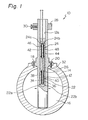
- Referring to Figure 1 of the drawings, there is shown a vortex flow meter furnished with a
vibration compensating apparatus 10 embodying the present invention. An elongatevortex shedding member 12 extends into aconduit 14 through which afluid 16 is allowed to flow. Thevortex shedder 12, having a triangular cross-section for example, is rigidly mounted to the wall of theconduit 14 by means ofscrews bore 12a extends axially through thevortex shedder 12 from the top toward the bottom and accomodates thereinside afirst oscillation sensor 22 inside of theconduit 14 and asecond oscillation sensor 24 outside of the same. The first andsecond oscillation sensors bore 12a by aglass envelope 26. Abalance weight 28 is coupled over thevortex shedder 12 adjacent to the outermost end of the latter. The position of thebalance weight 28 relative to theelement 12 is controllable as desired by means of an adjustingscrew 30. - The
first sensor 22 comprises aflat base plate 32 made of metal and extending substantially along the axis of thebore 12a, a pair ofpiezoelectric elements base plate 32, andmetal electrodes piezoelectric elements base plate 32 with thefirst sensor 22, thesecond sensor 24 comprises a pair ofpiezoelectric elements base plate 32, andmetal electrodes piezoelectric elements piezoelectric sensor 22a is formed by thebase plate 32,piezoelectric element 34 andelectrode 38 in thefirst sensor 22. Anotherpiezoelectric sensor 22b, which faces thesensor 22a, is formed by thebase plate 32,piezoelectric element 36 andelectrode 40. Likewise, thesecond sensor 24 has apiezoelectric sensor 24a formed by thebase plate 32,piezoelectric element 42 andelectrode 46, and anotherpiezoelectric sensor 24b formed by thebase plate 32,piezoelectric element 44 andelectrode 48, thepiezoelectric sensors - The first and
second sensors axial bore 12a of thevortex shedder 12 such that theelectrodes electrodes fluid 16 in theconduit 14. Stated another way, as shown in Figure 1, theelectrodes base plate 32 and so are theelectrodes - The
glass envelope 26 retaining thesensors bore 12a functions in three ways: completely insulating the sensors from the surrounding elements, causing the sensors to oscillate in a unitary structure with thevortex shedder 12, and enhancing the resistivity of the sensors to heat. Therefore, so long as these functions are satisfied, theenvelope 26 may be made of resin, ceramic or the like, instead of glass. - Referring to Figure 2, there are shown electrical connections of the sensor made up of the
piezoelectric sensors piezoelectric sensors second sensors charge amplifier 50, a low-passactive filter 52 and a Schmitt trigger 54. A pulse signal appears at anoutput terminal 56. - In operation, when the
fluid 16 flows through theconduit 14, a vortex train is shed in a known manner in a position downstream of that part of thevortex shedder 12 located inside of the conduit 14 (this part will be referred to as the "shedding portion" hereinafter). The vortex train causes the shedding portion of thevortex shedder 12 to oscillate substantially perpendicular to the flow of the fluid through theconduit 14, that is, in the lateral direction as seen in Figure 1. Thepiezoelectric sensors first sensor 22, which is integral with thevortex shedder 12 as mentioned earlier, sense the oscillations to deliver a signal proportional to the oscillation frequency. Here, due to the common interconnection of thepiezoelectric sensors first sensor 22 is entraining noise due to external oscillations which propagate through theconduit 14, in addition to the expected oscillations due to the vortex train. In detail, because thepiezoelectric sensors first sensor 22 face each other in the direction perpendicular to the fluid flow, they are hardly sensitive to oscillations parallel to the fluid flow and, if sensitive, the resulting outputs would cancel each other to not constitute any noise due to the differential interconnection of the electrodes. However, when it comes to externally derived oscillations of theconduit 14 perpendicular to the fluid flow andvortex shedder 12, they are allowed to reach the shedding portion of theshedder 12 to be detected together with the oscillations caused by the vortex train. - Meanwhile, the
second sensor 24 is adapted to sense only the external oscillations which are transferred through theconduit 14. As previously mentioned, thevortex shedder 12 is firmly fastened to theconduit 14 by means of thescrews shedder 12 is prevented from propagating outwardly beyond the fastened position to the remaining outer portion of the shedder 12 (this portion will be referred to as the "compensating portion" hereinafter). Thesecond sensor 24, therefore, is immune to oscillation except for those which are introduced intoconduit 14 from the outside. It will be noted that thesecond sensor 24 is common to the first 22 in sensing only the oscillations in the direction perpendicular to the fluid flow andshedder 12. - Now, consideration will be given to oscillations of the
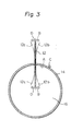
vortex shedder 12 originating from external oscillations which propagate through theconduit 14, with particular reference to Figure 3. In response to a leftward oscillation indicated by a dotted arrow A, both the shedding and compensating portions of theshedder 12 bend themselves to the right in the drawing as indicated by dotted arrows B, each fulcrumed by the interconnected portion of theshedder 12 andconduit 14. The resulting position of theshedder 12 is indicated by a dash-and-dot line 12b in the drawing. In response to a righward oscillation indicated by a solid arrow C, on the other hand, both the shedding and compensating portions of theshedder 12 bend to the left to a position indicated by a dash-and-dots line 12c. Therefore, the first andsecond sensors second sensor 24, however, it senses the composite oscillations of oscillations due to external oscillations and oscillations due to the vortex train. - With the above principles in mind, if the first and
second sensors second sensor 24 will cancel a noise component in the output of thefirst sensor 22 thereby leaving only the signal resulted from the vortex train. Because thesensors charge amplifier 50. The low-passactive filter 52 removes from the voltage variations high frequency components which have no bearing on the oscillations of thevortex shedder 12. The Schmitt trigger 54 processes an output of thefilter 52 into a rectangular pulse signal which accurately reflects an oscillation frequency provided by the vortex train only. Counting the output pusles of theSchmitt trigger 54 provides any instantaneous flow rate of the fluid 16. - The unique construction described, in which two
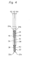
sensors shedder 12, affords the following advantage. Where one of the sensors is located inside theconduit 14 and the other outside the same, they receive exactly the same external oscillations and thereby pick up noise signals from theconduit 14 as exactly the same waveforms regardless of the direction or the like of the oscillations. As a result, a noise component will be completely cancelled when outputs of thesensors shedder 12 is in the liquid and the compensating portion in air, the oscillation modes of the shedding and compensating portions will differ from each other. Another factor that brings about a difference between their oscillation modes is derived externally, e.g., a difference in mass and/or shape between them. Any such difference in oscillation mode between the two portions can be readily eliminated by'shifting thebalance weight 30 to a desired position on theelement 12. - Referring to Figure 4, a modification to the sensor assembly of Figure 1 is illustrated. In Figure 4, the same reference numerals as those of Figure 1 designate the same structural elements. While in Figure 1 the
piezoelectric elements first sensor 22 are physically independent of theiradjacent counterparts second sensor 24, in Figure 4 the adjacent piezoelectric elements are replaced by a pair of commonpiezoelectric elements metal base plate 32; a terminal 62 is led out from theelectrodes elements electrodes elements - A circuit for processing outputs of the
sensors charge amplifier 50a connected to theoutput terminals first sensor 22, asecond charge amplifier 50b connected to theoutput terminals second oscillation sensor 24, avariable amplifier 66, and an adder or substractor 69. For the reason which will follow, the circuit of Figure 5 will prove effective when the output level of thefirst sensor 22 differs from that of the second 24. Although the waveform of noise included in the output of thefirst sensor 22 is in principle the same as the waveform of the output of thesecond sensor 24 as already discussed, a difference sometimes develops between the two output levels due to a difference in amplitude or the like between the inner and outer portions of theshedder 12. To eliminate this, the circuit of Figure 5 allows the output of theamplifier 66 and thereby that of thesecond sensor 24 to be adjusted such that the second sensor output reaches a same level as the first sensor output, which is provided through thecharge amplifier 50a. Then, the first and second sensor outputs will be combined by the adder orsubstractor 66 to remove the noise component. - It should be noted in Figure 5 that the low-pass
active filter 52 and Schmitt trigger 54 individually function in the same manner as those described with reference to Figure 2. - Referring to Figure 6, a cylindrical sensor assembly is shown as an alternative to the configuration of Figure 1 or 4. In Figure 6, the same reference numerals as those of Figure 1 or 4 designate the same structural elements. The
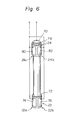
first sensor 22 shown in Figure 6 comprises acylindrical metal tube 70, an annularpiezoelectric element 72 mounted on thetube 70, and a pair ofmetal electrodes piezoelectric element 72 as by evaporation or gold paste baking in such a manner as to oppose each other. Thesecond sensor 24 shares themetal tube 70 with thefirst sensor 22 and has, in addition thereto, an annularpiezoelectric element 78 fit around thetube 70, and a pair ofmetal electrodes element 78 in the same manner as theelectrodes tube 70,piezoelectric element 72 andelectrode 74 constitute onepiezoelectric sensor 22a in combination, while thetube 70,piezoelectric element 72 andelectrode 76 constitute anotherpiezoelectric sensor 22b which faces thepiezoelectric sensor 22a. Further, thetube 70 cooperates with thepiezoelectric element 78 andelectrode 80 to form onepiezoelectric sensor 24a, while cooperating with thepiezoelectric element 78 andelectrode 82 to form anotherpiezoelectric sensor 24b, which faces thepiezoelectric sensor 24a. Again, the orientation of the sensor assembly inside theelement 12 is such that theelectrodes electrodes conduit 14. Stated another way, as in the case of Figure 1, theelectrodes electrodes - Shown in Figure 7 is a modification to the sensor assembly of Figure 6. In Figure 7, a
piezoelectric element 84 covers the whole outer periphery of themetal tube 70, in contrast to the spacedpiezoelectric elements electrodes first sensor 22 are carried on one axial end of thepiezoelectric element 84, while themetal electrodes second sensor 24 are carried on the other axial end of the same. - Still another modification to the cylindrical sensor configuration, particularly to that of Figure 6, is shown in Figure 8. A pair of spaced
piezoelectric elements metal tube 70 and a pair of spacedpiezoelectric elements piezoelectric element pair 72a-72b is a divided version of thepiezoelectric element 72 of Figure 6 and thepiezoelectric element pair 78a-78b, that of thepiezoelectric element 78. - The circuits shown in Figures 2 and 5 are selectively usable for processing output signals of the cylindrical oscillation sensor assemblies shown in Figure 6-8, just as they are used for the others.
- Now, an oscillation sensor using a piezoelectric element or the like has to have its electrode portions perfectly insulated from the surrounding members by means of glass or the like. This has heretofore been implemented by a method which fills the space concerned with glass powder and then heats the glass to melt and harden it, or a method which fills the space with a preformed glass. The problem encountered with the use of glass powder is that the filling and heating procedure has to be repeated several times because the volume of glass is smaller in the hardened state after heating than in the initial powdery state. The method using a preformed glass invites an increase in cost due to the intricate structure required therefor. In contrast, any one of the cylindrical sensor configurations shown in Figures 6-8 will facilitate the procedure for fixing the sensors within the
vortex shedding member 12. That is, it is possible to insert, melt and harden a cylindrical glass tube or preformed galss in the annular space between the wall of thebore 12a in theshedder 12 and the outer periphery of the sensors. This enveloping procedure does not need to be repeated inasmuch as the volume of the glass tube or preformed glass is free from reduction after hardening. Even the use of a preformed glass is cost-effective due to the simply cylindrical sensor configuration. - In summary, it will be seen that the present invention provides an oscillation compensating apparatus for a vortex flow meter which offers an excellent signal-to- noise ratio despite its simple and easy-to-produce structure.
- Various modifications will become possible for those skilled in the art after receiving the teachings of the present disclosure without departing from the scope thereof. For example, various other designs are applicable concerning the shape of the
vortex shedding member 12, fixing means therefor, means for fixing the sensors inside theshedder 12, configurations of the piezoelectric elements and electrodes of the sensors, circuit arrangement for combining the outputs of the sensors, etc. Thesensors shedder 12, instead of the integral structure on a single base plate or a tube shown and described.
Claims (24)
Applications Claiming Priority (2)
| Application Number | Priority Date | Filing Date | Title |
|---|---|---|---|
| JP126732/82 | 1982-07-22 | ||
| JP57126732A JPS5918422A (en) | 1982-07-22 | 1982-07-22 | Vibration compensating device for vortex flowmeter |
Publications (2)
| Publication Number | Publication Date |
|---|---|
| EP0100931A1 true EP0100931A1 (en) | 1984-02-22 |
| EP0100931B1 EP0100931B1 (en) | 1987-06-03 |
Family
ID=14942508
Family Applications (1)
| Application Number | Title | Priority Date | Filing Date |
|---|---|---|---|
| EP83107079A Expired EP0100931B1 (en) | 1982-07-22 | 1983-07-19 | Oscillation compensating apparatus for vortex flow meter |
Country Status (6)
| Country | Link |
|---|---|
| US (1) | US4526040A (en) |
| EP (1) | EP0100931B1 (en) |
| JP (1) | JPS5918422A (en) |
| KR (1) | KR870000458B1 (en) |
| CA (1) | CA1189349A (en) |
| DE (1) | DE3371941D1 (en) |
Cited By (4)
| Publication number | Priority date | Publication date | Assignee | Title |
|---|---|---|---|---|
| EP0549945A3 (en) * | 1991-12-30 | 1994-10-19 | Rota Yokogawa Gmbh & Co Kg | Flowmeter |
| DE102008025365A1 (en) | 2008-05-27 | 2009-12-03 | Stübbe, Peter | Non-invasive tooth bridge for use in dental laboratory, has casting mold for filling tooth gap with structural adhesive, and lining provided on front and/or upper side of bridge and comprising thin elastomer layer on its inner side |
| CN102279025A (en) * | 2011-06-30 | 2011-12-14 | 福建上润精密仪器有限公司 | Integrated gas mass flow meter for plug-in sensor integrated component |
| DE102010056279A1 (en) * | 2010-12-24 | 2012-06-28 | Abb Technology Ag | Vortex flowmeter with optimized temperature detection |
Families Citing this family (32)
| Publication number | Priority date | Publication date | Assignee | Title |
|---|---|---|---|---|
| JPS6023721U (en) * | 1983-07-26 | 1985-02-18 | オ−バル機器工業株式会社 | Vortex flowmeter vortex detection device |
| DE3377936D1 (en) * | 1982-11-25 | 1988-10-13 | Oval Eng Co Ltd | VORTEX FLOW METER |
| JPS607024U (en) * | 1983-06-28 | 1985-01-18 | オ−バル機器工業株式会社 | Microfluctuation pressure detector |
| JPS6130823U (en) * | 1984-07-27 | 1986-02-24 | オ−バル機器工業株式会社 | vortex flow meter |
| EP0144937B1 (en) * | 1983-12-02 | 1991-06-05 | Oval Engineering Co., Ltd. | Vortex flow meter |
| DE3544198A1 (en) * | 1985-12-13 | 1987-06-19 | Flowtec Ag | Vortex flow meter |
| US4862750A (en) * | 1987-02-11 | 1989-09-05 | Nice Gerald J | Vortex shedding fluid velocity meter |
| US5095760A (en) * | 1989-05-08 | 1992-03-17 | Lew Hyok S | Vortex flowmeter with dual sensors |
| US4984471A (en) * | 1989-09-08 | 1991-01-15 | Fisher Controls International, Inc. | Force transmitting mechanism for a vortex flowmeter |
| US5209125A (en) * | 1989-12-22 | 1993-05-11 | The Foxboro Company | Piezoelectric pressure sensor |
| US5003827A (en) * | 1989-12-22 | 1991-04-02 | The Foxboro Company | Piezoelectric differential pressure vortex sensor |
| US5197336A (en) * | 1990-01-29 | 1993-03-30 | Fuji Electric Co., Ltd. | Karman vortex flow meter |
| US5313843A (en) * | 1990-01-29 | 1994-05-24 | Fuji Electric Co., Ltd. | Karman vortex flow meter |
| US5220842A (en) * | 1990-12-31 | 1993-06-22 | Lew Hyok S | Vortex generator-sensor with pivotally balanced mass distribution |
| US5247838A (en) * | 1991-12-19 | 1993-09-28 | Badger Meter, Inc. | Double wing vortex flowmeter |
| US5347873A (en) * | 1993-04-09 | 1994-09-20 | Badger Meter, Inc. | Double wing vortex flowmeter with strouhal number corrector |
| US5561249A (en) * | 1993-12-23 | 1996-10-01 | Nice; Gerald J. | Insertable flow meter with dual sensors |
| DE4441129A1 (en) * | 1994-11-21 | 1996-05-23 | Junkalor Gmbh | Transducer for a vortex flow meter |
| KR100232471B1 (en) * | 1996-06-05 | 1999-12-01 | 류정열 | A fuel detecting method considered by a body vibration of a car |
| US5869772A (en) * | 1996-11-27 | 1999-02-09 | Storer; William James A. | Vortex flowmeter including cantilevered vortex and vibration sensing beams |
| US5804740A (en) * | 1997-01-17 | 1998-09-08 | The Foxboro Company | Capacitive vortex mass flow sensor |
| DE19723006A1 (en) * | 1997-06-02 | 1998-12-03 | Bailey Fischer & Porter Gmbh | Eddy frequency detection method for flow measuring device |
| US7073394B2 (en) * | 2004-04-05 | 2006-07-11 | Rosemount Inc. | Scalable averaging insertion vortex flow meter |
| US6973841B2 (en) * | 2004-04-16 | 2005-12-13 | Rosemount Inc. | High pressure retention vortex flow meter with reinforced flexure |
| JP4158980B2 (en) * | 2004-07-15 | 2008-10-01 | 株式会社オーバル | Multi vortex flowmeter |
| KR100868046B1 (en) * | 2006-11-28 | 2008-11-11 | 주식회사 세 바 | Vortex flowmeter |
| DE102012220505B4 (en) * | 2012-11-09 | 2016-10-20 | Gestra Ag | Monitoring a steam trap |
| GB201300403D0 (en) * | 2013-01-10 | 2013-02-20 | Smiths Medical Int Ltd | Flow sensors and apparatus |
| US9513147B2 (en) * | 2013-11-04 | 2016-12-06 | South Jersey Engineering & Research, LLC | Flowmeter comprising piezoelectric sensor |
| CN105006991A (en) * | 2015-07-22 | 2015-10-28 | 上海交通大学 | Laminated piezoelectric downhole energy collection device |
| JP2017067726A (en) * | 2015-10-02 | 2017-04-06 | サーパス工業株式会社 | Karman vortex flow meter |
| FR3117589B1 (en) | 2020-12-11 | 2023-07-28 | La Rochelle Univ | Device for measuring at least one flow parameter of a fluid |
Citations (4)
| Publication number | Priority date | Publication date | Assignee | Title |
|---|---|---|---|---|
| US3979954A (en) * | 1974-07-29 | 1976-09-14 | Hokushin Electric Works, Ltd. | Karman vortex flowmeter |
| US3991613A (en) * | 1975-03-10 | 1976-11-16 | Corning Glass Works | Sensing element for flow meter |
| GB2008752A (en) * | 1977-11-14 | 1979-06-06 | Yokogawa Electric Works Ltd | Vortex flow meter |
| US4248098A (en) * | 1977-05-30 | 1981-02-03 | Yokogawa Electric Works, Ltd. | Flow metering apparatus |
Family Cites Families (5)
| Publication number | Priority date | Publication date | Assignee | Title |
|---|---|---|---|---|
| US4186599A (en) * | 1976-12-29 | 1980-02-05 | Rosemount Inc. | Vortex shedding flowmeter assembly |
| DD141352A1 (en) * | 1979-02-09 | 1980-04-23 | Gisela Schmiedeberg | ARRANGEMENT FOR SWIVEL VOLUME FLOW MEASUREMENT |
| US4270391A (en) * | 1979-08-24 | 1981-06-02 | Fischer & Porter Co. | Frequency-responsive filter for flowmeter transmission system |
| US4362061A (en) * | 1981-02-04 | 1982-12-07 | Yokogawa Electric Works, Ltd. | Vortex shedding flow measuring device |
| JPS5860217A (en) * | 1981-10-06 | 1983-04-09 | Yokogawa Hokushin Electric Corp | Vortex flowmeter |
-
1982
- 1982-07-22 JP JP57126732A patent/JPS5918422A/en active Granted
-
1983
- 1983-07-18 US US06/515,090 patent/US4526040A/en not_active Expired - Lifetime
- 1983-07-19 EP EP83107079A patent/EP0100931B1/en not_active Expired
- 1983-07-19 DE DE8383107079T patent/DE3371941D1/en not_active Expired
- 1983-07-21 KR KR1019830003366A patent/KR870000458B1/en not_active IP Right Cessation
- 1983-07-21 CA CA000432864A patent/CA1189349A/en not_active Expired
Patent Citations (4)
| Publication number | Priority date | Publication date | Assignee | Title |
|---|---|---|---|---|
| US3979954A (en) * | 1974-07-29 | 1976-09-14 | Hokushin Electric Works, Ltd. | Karman vortex flowmeter |
| US3991613A (en) * | 1975-03-10 | 1976-11-16 | Corning Glass Works | Sensing element for flow meter |
| US4248098A (en) * | 1977-05-30 | 1981-02-03 | Yokogawa Electric Works, Ltd. | Flow metering apparatus |
| GB2008752A (en) * | 1977-11-14 | 1979-06-06 | Yokogawa Electric Works Ltd | Vortex flow meter |
Non-Patent Citations (1)
| Title |
|---|
| J.TICHY, G.GAUTSCHI "Piezoelektrische Messtechnik", 1st edition, 1980 SPRINGER-VERLAG, Berlin, Heidelberg, New York pages 158, 159 * |
Cited By (7)
| Publication number | Priority date | Publication date | Assignee | Title |
|---|---|---|---|---|
| EP0549945A3 (en) * | 1991-12-30 | 1994-10-19 | Rota Yokogawa Gmbh & Co Kg | Flowmeter |
| DE102008025365A1 (en) | 2008-05-27 | 2009-12-03 | Stübbe, Peter | Non-invasive tooth bridge for use in dental laboratory, has casting mold for filling tooth gap with structural adhesive, and lining provided on front and/or upper side of bridge and comprising thin elastomer layer on its inner side |
| DE102010056279A1 (en) * | 2010-12-24 | 2012-06-28 | Abb Technology Ag | Vortex flowmeter with optimized temperature detection |
| DE102010056279B4 (en) * | 2010-12-24 | 2013-07-04 | Abb Technology Ag | Vortex flowmeter with optimized temperature detection |
| US8910527B2 (en) | 2010-12-24 | 2014-12-16 | Abb Technology Ag | Vortex flowmeter with optimized temperature detection |
| CN102279025A (en) * | 2011-06-30 | 2011-12-14 | 福建上润精密仪器有限公司 | Integrated gas mass flow meter for plug-in sensor integrated component |
| CN102279025B (en) * | 2011-06-30 | 2013-02-20 | 福建上润精密仪器有限公司 | Integrated gas mass flow meter for plug-in sensor integrated component |
Also Published As
| Publication number | Publication date |
|---|---|
| DE3371941D1 (en) | 1987-07-09 |
| KR840005552A (en) | 1984-11-14 |
| US4526040A (en) | 1985-07-02 |
| KR870000458B1 (en) | 1987-03-11 |
| JPS6332127B2 (en) | 1988-06-28 |
| JPS5918422A (en) | 1984-01-30 |
| CA1189349A (en) | 1985-06-25 |
| EP0100931B1 (en) | 1987-06-03 |
Similar Documents
| Publication | Publication Date | Title |
|---|---|---|
| US4526040A (en) | Oscillation compensating apparatus for vortex flow meter | |
| CN110892235B (en) | Flowmeter sensor with interchangeable flow paths and related methods | |
| US4716770A (en) | Vortex flow meter | |
| US4422338A (en) | Method and apparatus for mass flow measurement | |
| US5492016A (en) | Capacitive melt pressure measurement with center-mounted electrode post | |
| EP0083144B1 (en) | Improved method and apparatus for mass flow measurement | |
| EP0359294A2 (en) | Coriolis mass flow rate meter and method for producing a mass flow rate signal with reduced harmonic content | |
| KR100186887B1 (en) | Electromagnetic flowmeter and method for electromagnetically measuring flow rate | |
| US4437350A (en) | Vortex flow metering apparatus | |
| US4201084A (en) | Vortex flow meter | |
| EP0364508A4 (en) | Vortex flowmeter | |
| US4088027A (en) | Force balance servo accelerometer | |
| JPS6332126B2 (en) | ||
| US5767419A (en) | Hall effect fluid flow switch and flow meter | |
| EP0415627B1 (en) | Acceleration sensor and acceleration sensing system | |
| US5036240A (en) | Impulse sensor with mechanical preamplification and noise cancellation | |
| US4976156A (en) | Impulse sensor with balanced mass-stiffness distribution | |
| US7523662B2 (en) | Process meter | |
| US6408700B1 (en) | Mass flow rate measurement circuit and method for a mass flow/density meter | |
| JP3049176B2 (en) | Vortex flowmeter and vortex sensor | |
| GB2068551A (en) | Vortex Shedding Flow Measuring Device | |
| JP4670152B2 (en) | Vortex flow meter | |
| JPH11258016A (en) | Vortex flow meter | |
| RU2083988C1 (en) | Molecular-electron converter of oscillatory accelerations | |
| JP4648625B2 (en) | Vortex flow meter |
Legal Events
| Date | Code | Title | Description |
|---|---|---|---|
| PUAI | Public reference made under article 153(3) epc to a published international application that has entered the european phase |
Free format text: ORIGINAL CODE: 0009012 |
|
| AK | Designated contracting states |
Designated state(s): CH DE FR GB LI NL |
|
| 17P | Request for examination filed |
Effective date: 19840731 |
|
| GRAA | (expected) grant |
Free format text: ORIGINAL CODE: 0009210 |
|
| AK | Designated contracting states |
Kind code of ref document: B1 Designated state(s): CH DE FR GB LI NL |
|
| REF | Corresponds to: |
Ref document number: 3371941 Country of ref document: DE Date of ref document: 19870709 |
|
| ET | Fr: translation filed | ||
| PLBE | No opposition filed within time limit |
Free format text: ORIGINAL CODE: 0009261 |
|
| STAA | Information on the status of an ep patent application or granted ep patent |
Free format text: STATUS: NO OPPOSITION FILED WITHIN TIME LIMIT |
|
| 26N | No opposition filed | ||
| PGFP | Annual fee paid to national office [announced via postgrant information from national office to epo] |
Ref country code: GB Payment date: 19980703 Year of fee payment: 16 |
|
| PGFP | Annual fee paid to national office [announced via postgrant information from national office to epo] |
Ref country code: FR Payment date: 19980717 Year of fee payment: 16 |
|
| PGFP | Annual fee paid to national office [announced via postgrant information from national office to epo] |
Ref country code: NL Payment date: 19980728 Year of fee payment: 16 |
|
| PGFP | Annual fee paid to national office [announced via postgrant information from national office to epo] |
Ref country code: CH Payment date: 19980818 Year of fee payment: 16 |
|
| PGFP | Annual fee paid to national office [announced via postgrant information from national office to epo] |
Ref country code: DE Payment date: 19980827 Year of fee payment: 16 |
|
| PG25 | Lapsed in a contracting state [announced via postgrant information from national office to epo] |
Ref country code: GB Free format text: LAPSE BECAUSE OF NON-PAYMENT OF DUE FEES Effective date: 19990719 |
|
| PG25 | Lapsed in a contracting state [announced via postgrant information from national office to epo] |
Ref country code: LI Free format text: LAPSE BECAUSE OF NON-PAYMENT OF DUE FEES Effective date: 19990731 Ref country code: FR Free format text: THE PATENT HAS BEEN ANNULLED BY A DECISION OF A NATIONAL AUTHORITY Effective date: 19990731 Ref country code: CH Free format text: LAPSE BECAUSE OF NON-PAYMENT OF DUE FEES Effective date: 19990731 |
|
| PG25 | Lapsed in a contracting state [announced via postgrant information from national office to epo] |
Ref country code: NL Free format text: LAPSE BECAUSE OF NON-PAYMENT OF DUE FEES Effective date: 20000201 |
|
| GBPC | Gb: european patent ceased through non-payment of renewal fee |
Effective date: 19990719 |
|
| REG | Reference to a national code |
Ref country code: CH Ref legal event code: PL |
|
| NLV4 | Nl: lapsed or anulled due to non-payment of the annual fee |
Effective date: 20000201 |
|
| PG25 | Lapsed in a contracting state [announced via postgrant information from national office to epo] |
Ref country code: DE Free format text: LAPSE BECAUSE OF NON-PAYMENT OF DUE FEES Effective date: 20000503 |
|
| REG | Reference to a national code |
Ref country code: FR Ref legal event code: ST |