EP0102285A1 - Electrical pressure contact incorporating closing and interrupting capability - Google Patents
Electrical pressure contact incorporating closing and interrupting capability Download PDFInfo
- Publication number
- EP0102285A1 EP0102285A1 EP83401610A EP83401610A EP0102285A1 EP 0102285 A1 EP0102285 A1 EP 0102285A1 EP 83401610 A EP83401610 A EP 83401610A EP 83401610 A EP83401610 A EP 83401610A EP 0102285 A1 EP0102285 A1 EP 0102285A1
- Authority
- EP
- European Patent Office
- Prior art keywords
- well
- stud
- heel
- moving part
- contact
- Prior art date
- Legal status (The legal status is an assumption and is not a legal conclusion. Google has not performed a legal analysis and makes no representation as to the accuracy of the status listed.)
- Granted
Links
Images

Classifications
-
- H—ELECTRICITY
- H01—ELECTRIC ELEMENTS
- H01R—ELECTRICALLY-CONDUCTIVE CONNECTIONS; STRUCTURAL ASSOCIATIONS OF A PLURALITY OF MUTUALLY-INSULATED ELECTRICAL CONNECTING ELEMENTS; COUPLING DEVICES; CURRENT COLLECTORS
- H01R13/00—Details of coupling devices of the kinds covered by groups H01R12/70 or H01R24/00 - H01R33/00
- H01R13/66—Structural association with built-in electrical component
- H01R13/70—Structural association with built-in electrical component with built-in switch
- H01R13/703—Structural association with built-in electrical component with built-in switch operated by engagement or disengagement of coupling parts, e.g. dual-continuity coupling part
- H01R13/7036—Structural association with built-in electrical component with built-in switch operated by engagement or disengagement of coupling parts, e.g. dual-continuity coupling part the switch being in series with coupling part, e.g. dead coupling, explosion proof coupling
-
- H—ELECTRICITY
- H01—ELECTRIC ELEMENTS
- H01H—ELECTRIC SWITCHES; RELAYS; SELECTORS; EMERGENCY PROTECTIVE DEVICES
- H01H5/00—Snap-action arrangements, i.e. in which during a single opening operation or a single closing operation energy is first stored and then released to produce or assist the contact movement
- H01H5/04—Energy stored by deformation of elastic members
- H01H5/14—Energy stored by deformation of elastic members by twisting of torsion members
- H01H5/16—Energy stored by deformation of elastic members by twisting of torsion members with auxiliary means for temporarily holding parts until torsion member is sufficiently strained
Definitions
- the invention relates to electrical pressure contacts and relates to a pressure contact with incorporated closing and opening power.
- Such a contact can be used in various devices such as a modular system, a disconnectable single-pole switch, etc., but it is particularly recommended for the equipment of industrial sockets,
- the invention provides a third type of pressure contact capable of giving them the breaking capacity of a switch, by producing a rocker which works parallel to the line of the contact elements,
- each contact becomes a single-pole switch with abrupt opening and closing and independent of the operator's operation
- the pressure contact intended to ensure the electrical connection between a conductive pin rigidly carried by the insulating support of a plug and a fixed stud electrically connected to an arrival terminal and disposed in a well formed in the insulating support.
- a base when the plug pin is inserted axially into the well of the base, the bodies of the plug and the base carrying combined guide means and locking to ensure and maintain this introduction, is remarkable in that it comprises a rigid and movable conductive part, disposed in the well of the base, extending over part of the depth of the latter, and intended to be pushed towards the bottom of the well by the free end of the spindle bearing on an end heel of said part, against an elastic means which tends to apply said heel against the orifice of the well, only means guide are provided to ensure the moving part a displacement substantially parallel to the axis of the contact until its end opposite the heel reaches the level of the stud connected to the arrival terminal and that the moving part and the means guide are arranged so that at the end of this movement parallel to the
- a pressure contact at the end is intended to ensure the electrical connection between a conductive pin 11 rigidly carried by the insulating support of a plug (not shown) and a fixed stud 12 electrically connected by a conductive strip 13 to an arrival terminal (not shown),
- the fixed stud 12 is disposed in a well 14, formed in the insulating support 15 of a base not otherwise shown, and having an orifice 16 allowing the axial introduction of the pin 11.
- This electrical connection between the elements 11 and 12 is produced by the guided longitudinal displacement, followed by a tilting , of a rigid conductive part 17 disposed in the well 14 and extending over part of the depth of said well 14,
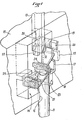
- the movable conductive part 17 is constituted by a plate (see in particular Figure 1), one end of which is bent twice at 90 ° to form a heel 18 in a U shape and the other end of which carries a stud 19 intended to cooperate with the fixed stud 12, has lateral appendages 20 giving it a T-shaped configuration,
- a second torsion coil spring 24 is intended to act on the part 17, one of its end branches being applied against said part on its face facing the wall 23 and the tube being disposed in the U formed by the heel 18,
- the end branch of the spring 21 engaged in this U is disposed inside the coil of the spring 24 and thus ensures the maintenance of the latter.
- the T-end, with its stud 19, of the part l7 is situated at a level lower than that of the legs 22, the axis of the contact being assumed to be vertical as in the drawing, the second end branch of the spring 24 is free from any constraint.
- the assembly is arranged in such a way that the stud 19 of the part 17 arrives at the level of the fixed stud 12, at the moment when the appendages 20 exceed the upper edge of the lugs 22 (figure; 2C and figure 1), action of the spring 24, the part 17 which is no longer retained by the lugs 22, tilts towards the wall of the well opposite the wall 23 and the stud 19 comes to abruptly apply against the fixed stud 22 (Figure 2 D) thus achieving the abrupt closure of the contact.
- the pin 11 After unlocking, the pin 11 is extracted by simple axial traction. The movement is facilitated by the action of the spring 21 which, by holding the heel 18 against the end of the pin 11, tends to drive the latter out of the well, Au start of the maneuver (FIG. 2E) the stud 19, still in elastic support against the fixed stud 12, by means of the spring 24, slides on said stud 12 thus causing self-cleaning of the contact surfaces.
- the studs 12 and 19 are semi-cylindrical.
Abstract
Selon l'invention, le contact destiné à assurer la liaison électrique entre une broche (11) de fiche et un plot fixe (12) d'alimentation disposé dans le puits (14) d'un socle, comporte une pièce conductrice mobile (17) disposée dans le socle, destinée à être repoussée par la broche (11) à l'encontre d'un moyen élastique (21) suivant une trajectoire parallèle à l'axe du contact, afin de se dégager de moyens de guidage (22) pour basculer ensuite brusquement, sous l'action d'un moyen élastique (24) jusqu'à la mise en contact d'un plot (19) porté par la pièce mobile (17) avec le plot fixe (12).According to the invention, the contact intended to ensure the electrical connection between a plug pin (11) and a fixed supply stud (12) disposed in the well (14) of a base, comprises a movable conductive part (17 ) disposed in the base, intended to be pushed back by the spindle (11) against an elastic means (21) along a path parallel to the axis of the contact, in order to disengage from guide means (22) to then switch suddenly, under the action of an elastic means (24) until a stud (19) carried by the moving part (17) is brought into contact with the fixed stud (12).
Application aux contacts de prises de courant industrielles.
Description
L'invention concerne les contacts électriques à pression et a pour objet un contact à pression à pouvoir de fermeture et d'ouverture incorporé.The invention relates to electrical pressure contacts and relates to a pressure contact with incorporated closing and opening power.
Un tel contact peut être utilisé dans divers dispositifs tels qu'un système modulaire, un interrupteur déconnectable unipolaire, etc., mais il est particulièrement recommandé pour l'équipement des prises de courant industrielles,Such a contact can be used in various devices such as a modular system, a disconnectable single-pole switch, etc., but it is particularly recommended for the equipment of industrial sockets,
En effet, les prises de courant industrielles doivent répondre aux règles définies par la publication 309-I de la Commission Electrotechnique Internationale qui fixe en particulier, pour chaquee calibre de prise de courant, un pouvoir de coupure minimum,Indeed, industrial sockets must comply with the rules defined by publication 309-I of the International Electrotechnical Commission which in particular fixes, for each rating of socket, a minimum breaking capacity,
Dans les prises à contacts glissants ( contacts par broches et alvéoles), la pression de contact est perpendiculaire au mouvement d'extraction de la broche, elle s'oppose à ce mouve- mentet le pouvoir de coupure est pratiquement inexistant. Pour répondre aux prescriptions susmentionnées, de telles prises devraient être verrouillées par un interrupteur,In sockets with sliding contacts (contacts by pins and cells), the contact pressure is perpendicular to the spindle extraction movement, it opposes this movement and the breaking capacity is practically nonexistent. To meet the above requirements, such sockets should be locked by a switch,
Dans les prises à contacts à pression, la pression de contact est parallèle au mouvement de séparation et favorise ce mouvement, il faut donc un moyen de verrouillage pour maintenir la pression de contact, Il suffit alors d'ajouter à ce moyen de verrouillage, un dispositif approprié de façon telle qu'au moment du déverrouillage les éléments de contact se séparent à une distance et avec une vitesse données, ce qui permet d'atteindre très aisément les caractéristiques définies par la publication 309-1 de la C.E.I.. Cependant, certains pays, en particulier les Etats-Unis, demandent que les prises de courant industrielles aient un pouvoir de coupure comparable à celui d'un interrupteur, c'est-à-dire qu'elles atteignent les performances imposées aux interrupteurs par la publication 408 de la C.E.I.. Avec les contacts à pression en bout actuellement existants, les prises de courant ne peuvent satisfaire à cette exigence car, au moment du déverrouillage et avant que les éléments de contact ne se séparent, la pression de contact qui était de quelques kilos , diminue pour devenir nulle au moment de la séparation et la vitesse de séparation est limitée par l'inertie du système,In pressure contact sockets, the contact pressure is parallel to the separation movement and promotes this movement, so a locking means is required to maintain the contact pressure. It is then sufficient to add to this locking means, a suitable device in such a way that at the time of unlocking the contact elements separate at a given distance and with a given speed, which makes it very easy to reach the characteristics defined by publication 309-1 of the IEC. However, certain countries, in particular the United States, require that industrial sockets have a breaking capacity comparable to that of a switch, that is to say that they achieve the performance imposed on switches by the IEC publication 408. With the existing end-to-end pressure contacts, sockets cannot meet this requirement because, at the time of unlocking and before the contact elements separate, the contact pressure, which was a few kilos, decreases to become zero at the time of separation and the separation speed is limited by the inertia of the system,
Deux types de contacts à pression sont actuellement utilisés:
- - pour des intensités inférieures à 250 ampères ces contacts comportent un contact élastique ayant une tête mobile montée sur un ressort, et reliée électriquement à un plot fixe de raccordement des conducteurs par une tresse coaxiale avec le ressort,
- - pour les intensités supérieures à 250 ampères ces contacts comportent une bascule qui travaille perpendiculairement à la ligne des éléments de contacts.
- - for intensities of less than 250 amps, these contacts comprise an elastic contact having a movable head mounted on a spring, and electrically connected to a fixed stud for connecting the conductors by a braid coaxial with the spring,
- - for the intensities higher than 250 amps these contacts comprise a rocker which works perpendicular to the line of the elements of contacts.
L'invention fournit un troisième type de contacts à pression capable de conférer à ceux-ci le pouvoir de coupure d'un interrupteur, en réalisant une bascule qui travaille parallèlement à la ligne des éléments de contact,The invention provides a third type of pressure contact capable of giving them the breaking capacity of a switch, by producing a rocker which works parallel to the line of the contact elements,
Un tel système présente naturellement, par rapport aux contacts utilisant une tresse, tous les avantages du contact à bascule, à savoir:
- a) la chute de tension du dispositif est garantie dans le temps, puisque contrairement au dispositif à tresse, les chutes de tension qui peuvent varier, n'existent qu"au point de contact ,
- b) les inconvénients de la brasure ou du sertissage de la tresse sont supprimés,
- c) la section de la bascule peut être au moins égale au plus gros conducteur pouvant être raccordé dans l'appareil,
- d) il y a un fort auto-nettoyage des contacts, résultant du mouvement de la bascule,
- a) the voltage drop of the device is guaranteed over time, since unlike the braided device, the voltage drops which can vary, exist only at the point of contact,
- b) the disadvantages of brazing or crimping the braid are eliminated,
- c) the section of the scale can be at least equal to the largest conductor that can be connected in the device,
- d) there is a strong self-cleaning of the contacts, resulting from the movement of the rocker,
En outre,ici, chaque contact devient un interrupteur unipolaire à ouverture et fermeture brusques et indépendantes de la manoeuvre de l'opérateur,In addition, here, each contact becomes a single-pole switch with abrupt opening and closing and independent of the operator's operation,
Selon l'invention le contact à pression destiné à assurer la liaison électrique entre une broche conductrice portée rigidement par le support isolant d'une fiche et un plot fixe relié électriquement à une borne d'arrivée et disposé dans un puits ménagé dans le support isolant d'un socle, lorsque la broche de fiche est introduite axialement dans le puits du socle, les corps de la fiche et du socle portant des moyens conjugués de guidage et de verrouillage pour assurer puis maintenir cette introduction, est remarquable en ce qu'il comporte une pièce conductrice rigide et mobile, disposée dans le puits du socle, s'étendant sur une partie de la profondeur de ce dernier, et destinée à être repoussée vers le fond du puits par l'extrémité libre de la broche prenant appui sur un talon d'extrémité de la dite pièce, à l'encontre d'un moyen élastique qui tend à appliquer ledit talon contre l'orifice du puits, que des moyens de guidage sont prévus pour assurer à la pièce mobile un déplacement sensiblement parallèle à l'axe du contact jusqu'à ce que son extrémité opposée au talon arrive au niveau du plot relié à la borne d'arrivée et que la pièce mobile et les moyens de guidage sont aménagés de façon telle qu'à la fin de ce déplacement parallèle à l'axe, la pièce mobile échappe aux dits moyens pour basculer et venir s'appliquer brusquement contre le plot sous l'action d'un moyen élastique, tandis que ce dernier moyen élastique contribue à assurer la rupture brusque du contact, lors du retrait de la broche de fiche, en accentuant le basculement de la pièce mobile,According to the invention, the pressure contact intended to ensure the electrical connection between a conductive pin rigidly carried by the insulating support of a plug and a fixed stud electrically connected to an arrival terminal and disposed in a well formed in the insulating support. a base, when the plug pin is inserted axially into the well of the base, the bodies of the plug and the base carrying combined guide means and locking to ensure and maintain this introduction, is remarkable in that it comprises a rigid and movable conductive part, disposed in the well of the base, extending over part of the depth of the latter, and intended to be pushed towards the bottom of the well by the free end of the spindle bearing on an end heel of said part, against an elastic means which tends to apply said heel against the orifice of the well, only means guide are provided to ensure the moving part a displacement substantially parallel to the axis of the contact until its end opposite the heel reaches the level of the stud connected to the arrival terminal and that the moving part and the means guide are arranged so that at the end of this movement parallel to the axis, the movable part escapes from said means for tilting and abruptly coming to bear against the stud under the action of an elastic means, while that this last elastic means contr ibue to ensure the abrupt break of the contact, during the withdrawal of the plug pin, by accentuating the tilting of the moving part,
On réalise ainsi un véritable interrupteur à ouverture et fermeture brusques tout en permettant des pressions de contact fortes et en respectant les règles de sécurité puisque le plot fixe, sous tension, ne peut être atteint accidentellement puisqu' il n'est accessible qu'en repoussant la pièce mobile,A real switch with abrupt opening and closing is thus produced while allowing strong contact pressures and respecting safety rules since the fixed stud, under tension, cannot be accidentally reached since it is only accessible by pushing back the moving part,
L' invention sera mieux comprise à la lecture de la description qui v&;suivre d'un de ses modes de réalisation, description qui se réfère au dessin annexé dans lequel;
- - la figure 1 est une perspective en coupe partielle d'un contact selon l'invention, et
- - les figures 2A à 2F des représentations schématiques, à plus petite échelle, les différentes phases de fonctionnement de la pièce mobile lors des manoeuvres d'enfoncement et de dégagement de la broche,
- FIG. 1 is a perspective in partial section of a contact according to the invention, and
- FIGS. 2A to 2 F are diagrammatic representations, on a smaller scale, of the different operating phases of the moving part during the insertion and disengagement operations of the spindle,
Sur le dessin, un contact à pression en bout est destiné à assurer la liaison électrique entre une broche conductrice 11 portée rigidement par le support isolant d'une fiche ( non représentée) et un plot fixe 12 relié électriquement par une lame conductrice 13 à une borne d'arrivée ( non représentée), Le plot fixe 12 est disposé dans un puits 14, ménagé dans le support isolant 15 d'u n socle non autrement représenté, et présentant un orifice 16 permettant l'introduction axiale de la broche 11. Cette liaison électrique entre les éléments 11 et 12 est réalisée par le déplacment longitudinal guidé, suivi d'un basculement, d'une pièce conductrice 17 rigide disposée dans le puits 14 et s'étendant sur une partie de la profondeur dudit puits 14,In the drawing, a pressure contact at the end is intended to ensure the electrical connection between a
Dans l'exemple représenté la pièce conductrice mobile 17, est constituée par une plaquette ( voir notamment figure 1) dont l'une des extrémités est courbée deux fois à 90° pour former un talon 18 en U et dont l'autre extrémité, qui porte un plot 19 destiné à coopérer avec le plot fixe 12, présente des appendices latéraux 20 lui donnant une configuration en T,In the example shown the movable
Au repos ( figure 2A), c'est à dire après retrait de la broche 11, la pièce 17 est sollicitée vers l'extérieur du puits 14, son talon 18 venant s'appliquer contre l'orifice 16, sous l'action d'un ressort de torsion à boudin 21 dont une branche d'extrémité est engagée dans le U formé par le talon 18 et l'autre calée et maintenue contre la paroi interne du puits 14,At rest (Figure 2A), that is to say after removal of the
Dans le puits 14 sont disposées transversalement, dans le prolongement l'unede l'autre, deux pattes 22 espacées de la paroi 23 du puits le long de laquelle doit se déplacer longitudinalement la pièce 17, L'écartement entre les bords en regard des deux pattes 22 est supérieur à la largeur de la partie médiane de la pièce 17, mais inférieur à la largeur de l'extrémité en T de ladite pièce,In the
Un second ressort de torsion à boudin 24 est destiné à agir' sur la pièce 17, l'une de ses branches d'extrémité étant appliquée contra ladite pièce sur sa face tournée vers la paroi 23 et le boudin étant disposé dans le U formé par le talon 18, Avantageusement, la branche d'extrémité du ressort 21 engagée dans ce U, est disposée à l'intérieur du boudin du ressort 24 et assure ainsi le maintien de ce dernier, Dans la position de repos (fig. 2A) susmentionnée, l'extrémité en T, avec son plot 19, de la pièce l7,est située à un niveau inférieur à celui des pattes 22, l'axe du contact étant supposé vertical comme sur le dessinât la seconde branche d'extrémité du ressort 24 est libre de toute contrainte.A second
Lorsque la broche 11 est introduite dans l'orifice 16 du puits 14, son extrémité libre vient s'appliquer contre le talon 18 de la pièce 17 et lorsque la manoeuvre d'introduction se poursuit la dite pièce est repoussée vers le fond du puits, Dans un premier temps( figure 2B) , les appendices 20 de la pièce 17 s'engagent entre la paroi 23 et les pattes de guidage 22 et, en même temps, l'extrémité libre du ressort 24 vient s'arc-bouter contre une saillie interne 25 du puits 14, saillie servant également au maintien du ressort 21.When the
L'introduction de la broche 11 se poursuivant, la pièce 17 se déplace , sensiblement parallèlement à elle-même, vers le fond du puits, les appendices 20 étant fermement appliqués contre les pattes 22 par l'action du ressort 24 ( figure 2C),The introduction of the
L'ensemble est aménagé de façon telle que le plot 19 de la pièce 17 arrive au niveau du plot fixe 12, au moment où les appendices 20 dépassent le bord supérieur des pattes 22 (figure; 2C et figure 1), Alors, sous l'action du ressort 24, la pièce 17 qui n'est plus retenue par les pattes 22, bascule vers la paroi du puits opposée à la paroi 23 et le plot 19 vient s'appliquer brusquement contre le plot fixe 22 (figure 2 D) réalisant ainsi la fermeture brusque du contact.The assembly is arranged in such a way that the
Bien entendu, à ce même moment, intervient un verrouillage immobilisant la broche 11, Ce verrouillage est obtenu par tout moyen connu, généralement par immobilisation relative de la fiche solidaire de la broche 11 par rapport au socle dans lequel est situé le puits 14, par exemple par une liaison à baïonnette,Of course, at this same moment, a locking action takes place immobilizing the
Après déverrouillage, l'extraction de la broche 11 s'effectue par simple traction axiale, Le mouvement est facilité par l'action du ressort 21 qui, en maintenant le talon 18 contre l'extrémité de la broche 11, tend à chasser cette dernière hors du puits, Au début de la manoeuvre ( figure 2E) le plot 19, toujours en appui élastique contre le plot fixe 12, grâce au ressort 24, glisse sur ledit plot 12 entrainant ainsi un auto-nettoyage des portées de contact. Avantageusement, pour assurer un fort auto-nettoyage les plots 12 et 19 sont hémicylindriques.After unlocking, the
L'extraction de la broche 11 se poursuivant, la pièce 17 continue à la suivre en direction de l'orifice 16 du puits et à un moment donné, le plot 19 échappe au plot 12 et, sous l'action du ressort 24, bascule brutalement vers la paroi opposée à la paroi 23 ( figure2 F) déterminant une ouverture brusque du contact. En même temps, la branche d'extrémité du ressort 24 s'éloigne de la saillie 25 et le dit ressort 24 devenant libre de toute contrainte, la pièce 17 n'est plus soumise qu'à l'action du ressort 21 qui applique alors la partie antérieure courbe du talon 18 contre l'extrémité de la broche 11. Le point de contact n'est pas à l'aplomb de la branche d'extrémité du ressort 21 et la pièce 17 tendà se redresser, la courbure du talon 18 facilitant ce mouvement et, à la fin de sa course, la pièce 17 vient s'appliquer par son talon sur l'orifice du puits reprenant sa position de repos (figure 2 A) dans l'attente d'une nouvelle introduction de la broche 11. Cependant d'autres moyens peuvent être imaginés pour guider le redressement de la pièce 17.The extraction of the
Ainsi le contact est devenu un véritable interrupteur unipolaire à ouverture et fermeture brusques,So the contact has become a real unipolar switch with abrupt opening and closing,
Tout ce qui précède se rapporte à un contact isolé, mais il est évident qu'une pluralité de tels contacts permet de réaliser différents dispositifs et, notamment, des prises de courant dans lesquels chaque contact, à l'exception éventuellement d'un contact de terre s'il existe, joue le rôle d'interrupteur et cela indépendamment de tous les aménagements connus susceptibles d'être utilisés( décalage angulaire d'au moins un contact, supports isolants à position angulaire variable, disque de sécurité simple ou double, etc,),All of the above relates to an isolated contact, but it is obvious that a plurality of such contacts makes it possible to produce different devices and, in particular, sockets in which each contact, with the possible exception of a contact of earth if it exists, plays the role of switch and this independently of all known arrangements which may be used (angular offset of at least one contact, insulating supports with variable angular position, single or double safety disc, etc. ,),
Claims (4)
Applications Claiming Priority (3)
| Application Number | Priority Date | Filing Date | Title |
|---|---|---|---|
| FR8213891A FR2531577A1 (en) | 1982-08-09 | 1982-08-09 | ELECTRIC PRESSURE CONTACT WITH CLOSURE AND OPENING POWER INCORPORATED |
| FR8213891 | 1982-08-09 | ||
| FR858504198A FR2579381B2 (en) | 1982-08-09 | 1985-03-21 | ELECTRICAL PRESSURE CONTACT WITH INCORPORATED CLOSING AND OPENING POWER |
Publications (2)
| Publication Number | Publication Date |
|---|---|
| EP0102285A1 true EP0102285A1 (en) | 1984-03-07 |
| EP0102285B1 EP0102285B1 (en) | 1986-04-09 |
Family
ID=26223037
Family Applications (1)
| Application Number | Title | Priority Date | Filing Date |
|---|---|---|---|
| EP83401610A Expired EP0102285B1 (en) | 1982-08-09 | 1983-08-03 | Electrical pressure contact incorporating closing and interrupting capability |
Country Status (6)
| Country | Link |
|---|---|
| US (2) | US4516819A (en) |
| EP (1) | EP0102285B1 (en) |
| JP (1) | JPS5949170A (en) |
| AU (1) | AU555434B2 (en) |
| CA (1) | CA1196943A (en) |
| FR (2) | FR2531577A1 (en) |
Cited By (3)
| Publication number | Priority date | Publication date | Assignee | Title |
|---|---|---|---|---|
| FR2579381A2 (en) * | 1982-08-09 | 1986-09-26 | Marechal Sepm | ELECTRIC PRESSURE CONTACT WITH CLOSURE AND OPENING POWER INCORPORATED |
| FR2737601A1 (en) * | 1995-08-01 | 1997-02-07 | Berdanos Guy | Low voltage isolation switch responding to high voltage pulse for use in telecommunications - has high insulation pair of switch sets possessing high cut=off power, one of which forms rapid disconnection set, for several circuits |
| CN102543593A (en) * | 2012-03-08 | 2012-07-04 | 江苏辉能电气有限公司 | Method for mounting rotating shaft of molded case circuit breaker |
Families Citing this family (11)
| Publication number | Priority date | Publication date | Assignee | Title |
|---|---|---|---|---|
| FR2586460B1 (en) * | 1985-08-21 | 1987-11-06 | Marechal Sepm | ANTI-INVERSION DEVICE FOR THE RELATIVE MOTION OF TWO RESPECTIVELY MALE AND FEMALE ORGANS, ONE OF WHICH IS MANUALLY ACTUATED |
| FR2623945B1 (en) * | 1987-11-30 | 1990-04-27 | Marechal Sepm | POWER SOCKET WITH PRESSURE CONTACTS |
| US5013877A (en) * | 1988-02-08 | 1991-05-07 | Raychem Corporation | Devices for electrical connection |
| US5476391A (en) * | 1993-06-15 | 1995-12-19 | Sumitomo Wiring Systems, Ltd. | Lever type connector assembly |
| FR2756669B1 (en) * | 1996-12-02 | 1998-12-31 | Marechal Sepm | ELECTRICAL CONNECTION DEVICE WITH LOCKING IN OPENING POSITION |
| US6250454B1 (en) | 1999-06-23 | 2001-06-26 | Danville Automation Holdings, Llc | Storage buffer for a multi lane conveyor |
| US6485318B1 (en) | 2001-11-13 | 2002-11-26 | Delphi Technologies, Inc. | Electrical shuttle connector |
| JP4179397B1 (en) * | 2007-07-04 | 2008-11-12 | オムロン株式会社 | switch |
| JP5556237B2 (en) * | 2010-02-26 | 2014-07-23 | オムロン株式会社 | switch |
| EP3410143B1 (en) * | 2017-05-31 | 2019-07-10 | Siemens Healthcare GmbH | Connector for use in a magnetic resonance device |
| US10971868B2 (en) * | 2019-02-20 | 2021-04-06 | TE Connectivity Services Gmbh | Electrical/mechanical switching module |
Citations (7)
| Publication number | Priority date | Publication date | Assignee | Title |
|---|---|---|---|---|
| GB191213455A (en) * | 1912-06-08 | 1913-04-24 | Albert Wynne | Improvements in or relating to Electrical Switches. |
| US1754585A (en) * | 1924-06-04 | 1930-04-15 | Square D Co | Electric switch |
| GB497810A (en) * | 1937-09-03 | 1938-12-29 | John Bristow Tucker | Improvements relating to electrical plug and socket connectors |
| FR1157309A (en) * | 1955-05-23 | 1958-05-28 | Ciba Geigy | Explosion-proof electrical distribution or control equipment |
| CH356812A (en) * | 1957-05-28 | 1961-09-15 | Doebelin Hennig Rudolf | Three-pole socket |
| DE1242735B (en) * | 1965-04-21 | 1967-06-22 | Marquardt J & J | Electrical snap-action switch actuated by a plunger |
| EP0053194A1 (en) * | 1980-11-28 | 1982-06-09 | Square D Starkstrom GmbH | Contact device |
Family Cites Families (5)
| Publication number | Priority date | Publication date | Assignee | Title |
|---|---|---|---|---|
| US1470824A (en) * | 1919-07-21 | 1923-10-16 | E H Freeman Electric Company | Electrical connector device |
| US3370141A (en) * | 1965-10-21 | 1968-02-20 | Garamszegi Charles | Electrical receptacle having zero potential until an electrical plug is positioned therein and including circuit breaker means |
| DE2008420A1 (en) * | 1970-02-24 | 1971-09-02 | Klieber H | Two or multi-pole electrical safety plug-in device |
| DE2030264A1 (en) * | 1970-06-19 | 1971-12-23 | Kabel Metallwerke Ghh | Coupling element for connecting electrical lines |
| FR2531577A1 (en) * | 1982-08-09 | 1984-02-10 | Marechal Sepm | ELECTRIC PRESSURE CONTACT WITH CLOSURE AND OPENING POWER INCORPORATED |
-
1982
- 1982-08-09 FR FR8213891A patent/FR2531577A1/en active Granted
-
1983
- 1983-07-29 JP JP58139316A patent/JPS5949170A/en active Granted
- 1983-08-02 AU AU17500/83A patent/AU555434B2/en not_active Ceased
- 1983-08-03 EP EP83401610A patent/EP0102285B1/en not_active Expired
- 1983-08-03 US US06/519,868 patent/US4516819A/en not_active Expired - Lifetime
- 1983-08-08 CA CA000434091A patent/CA1196943A/en not_active Expired
-
1985
- 1985-03-21 FR FR858504198A patent/FR2579381B2/en not_active Expired
- 1985-05-09 US US06/732,294 patent/US4632481A/en not_active Expired - Lifetime
Patent Citations (7)
| Publication number | Priority date | Publication date | Assignee | Title |
|---|---|---|---|---|
| GB191213455A (en) * | 1912-06-08 | 1913-04-24 | Albert Wynne | Improvements in or relating to Electrical Switches. |
| US1754585A (en) * | 1924-06-04 | 1930-04-15 | Square D Co | Electric switch |
| GB497810A (en) * | 1937-09-03 | 1938-12-29 | John Bristow Tucker | Improvements relating to electrical plug and socket connectors |
| FR1157309A (en) * | 1955-05-23 | 1958-05-28 | Ciba Geigy | Explosion-proof electrical distribution or control equipment |
| CH356812A (en) * | 1957-05-28 | 1961-09-15 | Doebelin Hennig Rudolf | Three-pole socket |
| DE1242735B (en) * | 1965-04-21 | 1967-06-22 | Marquardt J & J | Electrical snap-action switch actuated by a plunger |
| EP0053194A1 (en) * | 1980-11-28 | 1982-06-09 | Square D Starkstrom GmbH | Contact device |
Cited By (4)
| Publication number | Priority date | Publication date | Assignee | Title |
|---|---|---|---|---|
| FR2579381A2 (en) * | 1982-08-09 | 1986-09-26 | Marechal Sepm | ELECTRIC PRESSURE CONTACT WITH CLOSURE AND OPENING POWER INCORPORATED |
| FR2737601A1 (en) * | 1995-08-01 | 1997-02-07 | Berdanos Guy | Low voltage isolation switch responding to high voltage pulse for use in telecommunications - has high insulation pair of switch sets possessing high cut=off power, one of which forms rapid disconnection set, for several circuits |
| CN102543593A (en) * | 2012-03-08 | 2012-07-04 | 江苏辉能电气有限公司 | Method for mounting rotating shaft of molded case circuit breaker |
| CN102543593B (en) * | 2012-03-08 | 2014-06-04 | 江苏辉能电气有限公司 | Method for mounting rotating shaft of molded case circuit breaker |
Also Published As
| Publication number | Publication date |
|---|---|
| JPS5949170A (en) | 1984-03-21 |
| CA1196943A (en) | 1985-11-19 |
| FR2531577A1 (en) | 1984-02-10 |
| AU555434B2 (en) | 1986-09-25 |
| FR2579381A2 (en) | 1986-09-26 |
| FR2531577B1 (en) | 1984-12-28 |
| FR2579381B2 (en) | 1989-06-30 |
| US4632481A (en) | 1986-12-30 |
| JPH0332859B2 (en) | 1991-05-15 |
| EP0102285B1 (en) | 1986-04-09 |
| AU1750083A (en) | 1984-02-16 |
| US4516819A (en) | 1985-05-14 |
Similar Documents
| Publication | Publication Date | Title |
|---|---|---|
| EP0102285B1 (en) | Electrical pressure contact incorporating closing and interrupting capability | |
| EP1729376B1 (en) | Locking lever mechanism for connector | |
| FR2580432A1 (en) | CONNECTING CONNECTOR FOR ELECTRICAL CONDUCTORS | |
| EP0743702B1 (en) | Device for electrical contacts with insulation displacement | |
| EP0020241B1 (en) | Connecting device for insulated electrical conductors | |
| EP0505256B1 (en) | Two part adapter for connection of an electrical apparatus by plug and socket | |
| EP0596776B1 (en) | Contact bank with adaptable labelling | |
| FR2541815A1 (en) | ELECTROMAGNETIC RELAY WITH ARTICULATED FRAME | |
| EP3646413B1 (en) | Electrical connection mount comprising a movable connection element, additional electrical connection mount, and assembly comprising such mounts | |
| EP2456021B1 (en) | Electric socket comprising translatably mobile side posts | |
| EP0087158B1 (en) | Polyvalent electrical connector | |
| EP0805605A1 (en) | Interconnecting device for transmission networks, especially for telephony and data processing | |
| EP3487006B1 (en) | Electrical system comprising an electrical apparatus and an interchangeable connector module | |
| WO2016087799A1 (en) | Electrical connection element penetrating an electrical wire insulation sheath | |
| EP2503644B1 (en) | Electrical device of terminal block type | |
| FR2794902A1 (en) | COMPACT BYPASS CONNECTOR OF AT LEAST ONE NEUTRAL BYPASS CABLE ON A MAIN NEUTRAL AND SIMULTANEOUS GROUNDED CABLE | |
| EP1030409B1 (en) | Device having at least a diode laser, assembly comprising such a device and a connector for electrical power supply | |
| FR2782577A1 (en) | Low insertion force connector; has guide slots enabling insertion and subsequent pivoting into secure contact position | |
| FR3034263B1 (en) | "UNITARY MINIATURE ELECTRICAL CONNECTOR WITH EXTRACTIBLE CONTACT ELEMENTS AND ASSOCIATED TOOL FOR UNLOCKING AND EXTRACTING CONTACT ELEMENTS" | |
| EP0949718B1 (en) | Connecting/disconnecting module for insulated electrical conductor pairs | |
| CH660257A5 (en) | FUSE HOLDER. | |
| FR2782576A1 (en) | Reduced insertion force connection for multiple contacts; has pivoting system to close contacts after insertion, without large force | |
| EP1612889B1 (en) | Terminal with leaf spring for reduced insertion force | |
| EP2538495A1 (en) | Electrical clamp connection for electrical equipment contact and electric apparatus equipped with such clamp connection | |
| EP3651273A1 (en) | Device for electrical connection of the downstream terminals of an electrical protection device |
Legal Events
| Date | Code | Title | Description |
|---|---|---|---|
| PUAI | Public reference made under article 153(3) epc to a published international application that has entered the european phase |
Free format text: ORIGINAL CODE: 0009012 |
|
| AK | Designated contracting states |
Designated state(s): DE GB IT |
|
| 17P | Request for examination filed |
Effective date: 19840404 |
|
| ITF | It: translation for a ep patent filed |
Owner name: LENZI & C. |
|
| GRAA | (expected) grant |
Free format text: ORIGINAL CODE: 0009210 |
|
| AK | Designated contracting states |
Kind code of ref document: B1 Designated state(s): DE GB IT |
|
| REF | Corresponds to: |
Ref document number: 3362922 Country of ref document: DE Date of ref document: 19860515 |
|
| PLBE | No opposition filed within time limit |
Free format text: ORIGINAL CODE: 0009261 |
|
| STAA | Information on the status of an ep patent application or granted ep patent |
Free format text: STATUS: NO OPPOSITION FILED WITHIN TIME LIMIT |
|
| 26N | No opposition filed | ||
| ITTA | It: last paid annual fee | ||
| PGFP | Annual fee paid to national office [announced via postgrant information from national office to epo] |
Ref country code: GB Payment date: 20010718 Year of fee payment: 19 |
|
| PGFP | Annual fee paid to national office [announced via postgrant information from national office to epo] |
Ref country code: DE Payment date: 20011025 Year of fee payment: 19 |
|
| REG | Reference to a national code |
Ref country code: GB Ref legal event code: IF02 |
|
| PG25 | Lapsed in a contracting state [announced via postgrant information from national office to epo] |
Ref country code: GB Free format text: LAPSE BECAUSE OF NON-PAYMENT OF DUE FEES Effective date: 20020803 |
|
| PG25 | Lapsed in a contracting state [announced via postgrant information from national office to epo] |
Ref country code: DE Free format text: LAPSE BECAUSE OF NON-PAYMENT OF DUE FEES Effective date: 20030301 |
|
| GBPC | Gb: european patent ceased through non-payment of renewal fee |
Effective date: 20020803 |