EP0103491B1 - Method and apparatus for providing feedback-controlled muscle stimulation - Google Patents
Method and apparatus for providing feedback-controlled muscle stimulation Download PDFInfo
- Publication number
- EP0103491B1 EP0103491B1 EP83305389A EP83305389A EP0103491B1 EP 0103491 B1 EP0103491 B1 EP 0103491B1 EP 83305389 A EP83305389 A EP 83305389A EP 83305389 A EP83305389 A EP 83305389A EP 0103491 B1 EP0103491 B1 EP 0103491B1
- Authority
- EP
- European Patent Office
- Prior art keywords
- stimulation
- generating
- signal
- muscle
- limb
- Prior art date
- Legal status (The legal status is an assumption and is not a legal conclusion. Google has not performed a legal analysis and makes no representation as to the accuracy of the status listed.)
- Expired
Links
- 230000000638 stimulation Effects 0.000 title claims description 66
- 210000003205 muscle Anatomy 0.000 title claims description 52
- 238000000034 method Methods 0.000 title claims description 23
- 230000033001 locomotion Effects 0.000 claims description 22
- 230000004936 stimulating effect Effects 0.000 claims description 8
- 206010033799 Paralysis Diseases 0.000 claims description 6
- 230000000694 effects Effects 0.000 claims description 6
- 230000004044 response Effects 0.000 claims description 6
- 230000003387 muscular Effects 0.000 claims description 5
- 238000003745 diagnosis Methods 0.000 claims description 2
- 230000008602 contraction Effects 0.000 description 8
- 230000003189 isokinetic effect Effects 0.000 description 7
- 238000004804 winding Methods 0.000 description 6
- 230000006378 damage Effects 0.000 description 4
- 210000005036 nerve Anatomy 0.000 description 4
- 238000002560 therapeutic procedure Methods 0.000 description 4
- 240000007643 Phytolacca americana Species 0.000 description 3
- 238000005452 bending Methods 0.000 description 3
- 239000003990 capacitor Substances 0.000 description 3
- 230000007423 decrease Effects 0.000 description 3
- 230000003247 decreasing effect Effects 0.000 description 3
- 230000007115 recruitment Effects 0.000 description 3
- 230000001225 therapeutic effect Effects 0.000 description 3
- 238000006243 chemical reaction Methods 0.000 description 2
- 238000004590 computer program Methods 0.000 description 2
- 230000000994 depressogenic effect Effects 0.000 description 2
- 230000006870 function Effects 0.000 description 2
- 238000005259 measurement Methods 0.000 description 2
- 230000002093 peripheral effect Effects 0.000 description 2
- 210000003314 quadriceps muscle Anatomy 0.000 description 2
- 239000004065 semiconductor Substances 0.000 description 2
- 210000000278 spinal cord Anatomy 0.000 description 2
- 230000002459 sustained effect Effects 0.000 description 2
- 238000012360 testing method Methods 0.000 description 2
- 206010049565 Muscle fatigue Diseases 0.000 description 1
- 206010049816 Muscle tightness Diseases 0.000 description 1
- 239000004696 Poly ether ether ketone Substances 0.000 description 1
- 229910000831 Steel Inorganic materials 0.000 description 1
- 230000009471 action Effects 0.000 description 1
- 230000003213 activating effect Effects 0.000 description 1
- JUPQTSLXMOCDHR-UHFFFAOYSA-N benzene-1,4-diol;bis(4-fluorophenyl)methanone Chemical compound OC1=CC=C(O)C=C1.C1=CC(F)=CC=C1C(=O)C1=CC=C(F)C=C1 JUPQTSLXMOCDHR-UHFFFAOYSA-N 0.000 description 1
- 238000010276 construction Methods 0.000 description 1
- 230000008878 coupling Effects 0.000 description 1
- 238000010168 coupling process Methods 0.000 description 1
- 238000005859 coupling reaction Methods 0.000 description 1
- 230000006866 deterioration Effects 0.000 description 1
- 239000003814 drug Substances 0.000 description 1
- 230000005611 electricity Effects 0.000 description 1
- 239000004744 fabric Substances 0.000 description 1
- 239000000835 fiber Substances 0.000 description 1
- 238000010304 firing Methods 0.000 description 1
- 230000000774 hypoallergenic effect Effects 0.000 description 1
- 238000012544 monitoring process Methods 0.000 description 1
- 210000002161 motor neuron Anatomy 0.000 description 1
- 230000004118 muscle contraction Effects 0.000 description 1
- 210000004126 nerve fiber Anatomy 0.000 description 1
- 210000002569 neuron Anatomy 0.000 description 1
- 229920002530 polyetherether ketone Polymers 0.000 description 1
- 230000008569 process Effects 0.000 description 1
- 238000012545 processing Methods 0.000 description 1
- 230000000630 rising effect Effects 0.000 description 1
- 210000002027 skeletal muscle Anatomy 0.000 description 1
- 239000010959 steel Substances 0.000 description 1
- 229940124597 therapeutic agent Drugs 0.000 description 1
- 238000012546 transfer Methods 0.000 description 1
Images


Classifications
-
- A—HUMAN NECESSITIES
- A61—MEDICAL OR VETERINARY SCIENCE; HYGIENE
- A61N—ELECTROTHERAPY; MAGNETOTHERAPY; RADIATION THERAPY; ULTRASOUND THERAPY
- A61N1/00—Electrotherapy; Circuits therefor
- A61N1/18—Applying electric currents by contact electrodes
- A61N1/32—Applying electric currents by contact electrodes alternating or intermittent currents
- A61N1/36—Applying electric currents by contact electrodes alternating or intermittent currents for stimulation
- A61N1/36003—Applying electric currents by contact electrodes alternating or intermittent currents for stimulation of motor muscles, e.g. for walking assistance
-
- Y—GENERAL TAGGING OF NEW TECHNOLOGICAL DEVELOPMENTS; GENERAL TAGGING OF CROSS-SECTIONAL TECHNOLOGIES SPANNING OVER SEVERAL SECTIONS OF THE IPC; TECHNICAL SUBJECTS COVERED BY FORMER USPC CROSS-REFERENCE ART COLLECTIONS [XRACs] AND DIGESTS
- Y10—TECHNICAL SUBJECTS COVERED BY FORMER USPC
- Y10S—TECHNICAL SUBJECTS COVERED BY FORMER USPC CROSS-REFERENCE ART COLLECTIONS [XRACs] AND DIGESTS
- Y10S128/00—Surgery
- Y10S128/905—Feedback to patient of biological signal other than brain electric signal
Definitions
- the present invention relates to a method and apparatus for electrically stimulating muscle and, more particularly, to a computer controlled method and apparatus for monitoring muscular activity and adjusting an electrical stimulus to provide controlled and sustained isokinetic contractions. Still more particularly the present invention relates to a method and apparatus for directing coordinated movement of several muscles and exercising them through a specific exercise routine.
- the invention which is disclosed and claimed herein has particular value in the treatment of persons who have suffered injuries resulting in spinal cord damage. This particular type of damage often times produces partial or total paralysis of muscles which are controlled from a point below the point of spinal cord damage. The victim then faces a life of relative inactivity and deterioration of muscles which otherwise would be active. It has now been found that such muscles can be stimulated to engage in an exercise program once thought to be impossible. Moreover, it has been found that such an exercise program can restore normal muscle tone, even after years of inactivity.
- U.S. Patent No. 3,387,147 (1968) discloses a muscle stimulating pulse generator designed to provide a pulse signal having a relatively high voltage-to-width ratio and a steep rising wavefront.
- Maurer U.S. Patent No. 3,817,254 (1974), discloses a transcutaneous stimulator for use in suppressing pain designed to differentially stimulate touch versus pain nerve fibres in an effort to reduce the prickly sensation known to accompany some pain therapy.
- Maurer notes that differences in the response of nerves to electro-stimulation can be used to selectively stimulate different types of nerves.
- nerve fibers are distinguished in terms of their size and conduction velocity. He notes that the amplitude of electrical stimulation required to elicit a muscle response increases as the fiber size decreases.
- Wyss et al U.S. Patent No. 4,148,321 (1979), discloses a muscular therapy similar in some respects to Nawracaj et al wherein muscles are made to rhythmically contract and relax at a very low frequency which is induced by modulating a medium frequency current between 3,000 and 100,000 Hz with a low frequency current less than 1 Hz.
- Wyss et al uses a phase shifter to transform the modulated alternating output current into a three phase alternating current, which is delivered to three electrodes angularly spaced about a limb to provide deep uniform stimulation.
- Petrofsky "Microprocessor Controlled Stimulation in Paralyzed Muscle", IEEE August 1979 outlines a computer-controlled stimulation system which mimics normal asynchronous recruitment of motor units and firing rate control in the gastrocnemius muscle of a cat.
- a computer was programmed to set the recruitment order of the motor units as it sensed fatigue in the muscle. This was accomplished by using an anodal block electrode in combination with a sequential electrode sleeve. The electrode sleeve was placed around the motor nerve to the muscle and was configured for alternately stimulating three groups of neurons in the nerve. The anodal block electrode was placed just proximal to the muscle. Muscle fatigue was sensed by a strain gauge transducer mounted on a bar attached to one end of the muscle.
- the Petrofsky article teaches that electrostimulation can be controlled by a microprocessor in such a way as to develop isometric contractions in a muscle. However, there is no teaching of any method or apparatus for causing smooth, natural isokinetic contractions. Also, the techniques taught by Petrofsky are not applied to man.
- the invention provides apparatus for stimulating muscular activity in a paralyzed human limb comprising control means for generating a stimulation control signal, stimulation means responsive to said control signal for generating a series of stimulation signals and electrode means for applying said stimulation signals to a control muscle for said limb; characterised in that said control means comprise feedback means (17) responsive to motion of said limb for generating a corresponding feedback signal and computing means (12, 13, 14) responsive to said feedback signal for generating said stimulation control signal; said stimulation means comprise pulse generating means (101, 102, 103) for causing said stimulation signals to be generated as a pair of pulse trains, the pulses in one train alternating with those of the other train; and said electrode means comprise at least three electrodes (15a, 15b, 15c) connected in pairs for alternate energisation by said pulse trains.
- the invention provides a method of causing movement of a paralyzed human limb (the method not being one for treatment or diagnosis) comprising the steps of generating a stimulation control signal, generating electrical stimulation signals in response to said control signal and applying said stimulation signals to a muscle connected for producing movement of said limb; characterised in that said control signal is varied by generating a feedback signal corresponding to the motion of said limb and said control signal is adjusted in accordance with variations in said feedback signal; said stimulation signals comprising a pair of pulse trains, the pulses in one train alternating with those of the other train, and are applied to the muscle through at least three electrodes connected in pairs for alternate energisation by the pulse trains.
- the stimulation apparatus is controlled through a digital to analog converter by a digitally controlled microprocessor.
- the limb which is moved by the stimulated muscle is secured against a dynamic load which yieldingly resists movement of the muscle.
- a feedback sensor senses the movement actually achieved by the limb and transmits an indication thereof through an analog to digital converter back to the microprocessor.
- a plurality of transcutaneous stimulators are applied to the skin of the subject in a pattern for stimulating a muscle which is connected for moving the limb to be exercised.
- the stimulators are then excited by a plurality of stimulation signals having profiles for causing the muscle to contract and produce a predetermined movement of the limb.
- a resisting force is applied thereagainst to cause exertion of the muscle during its contraction.
- the movement of the limb is sensed and a corresponding feedback signal is generated.
- the feedback signal is monitored to determine when a predetermined movement has been achieved.
- the stimulation signals are altered to permit the limb to return to its initial position. The process is then repeated to produce an exercise routine.
- Exercise system 10 also comprises a seat belt 18 for securing a person in chair 16 and a leg strap 19 for grasping the lower portion of a leg 31.
- Leg strap 19 is provided with interlocking pieces of hook and loop fastening fabric 20, 20 of the type sold by Velcro U.S.A., Inc. of New York, New York under the trademark Velcro.
- Velcro U.S.A., Inc. of New York, New York under the trademark Velcro.
- Leg strap 19 has a steel eyelet for fastening to one or the other of a pair of scissor-type eyelet fasteners 21, 22.
- Fasteners 21 and 22 are attached to pair of cables 33, 34, respectively, which extend through a facing board 24.
- Cables 33 and 34 are guided by a roller 23 having a pair of offset guide channels (not illustrated). Cable 33 extends rearwardly from roller 23 around a roller 36 and thence upwardly for attachment to a toothed belt 35. Cable 34 wraps around roller 23 and extends upwardly for attachment to a relatively stiff bending arm 25 supported upon frame member 39, as best illustrated in Fig. 3.
- Toothed belt 35 extends around a pair of toothed rollers 37 and 38 mounted between a pair of support plates 41 a and 41 b, as best illustrated in Fig. 4.
- Support plates 41 a and 41 b are securely supported by frame member 40, which in turn is supported by frame member 39.
- Belt 35 supports a set of weights 27 placed upon a pan 42. Thus when the leg 31 moves arcuately as indicated by arrow 46, the weights 27 are raised or lowered.
- the arrangement provides a dynamic load which resists but does not prevent movement of leg 31.
- potentiometer 17 When the leg 31 is extended upwardly, pulling cable 33 and belt 35, the movement is measured by a potentiometer 17 (see Fig. 4) attached to roller 38 by a coupling device 44'.
- the housing for potentiometer 17 is supported by a support arm 43 secured to the upper support plate 41, as viewed in Fig. 4.
- the potentiometer 17 transmits a feedback signal to A/D converter 12.
- A/D converter 12 converts the feedback signal into a digital format for processing by computer 13, as hereinafter described in detail.
- Computer 13 responds to the feedback signal by transmitting a digital control signal to D/A converter 14.
- D/A converter 14 then generates an analog stimulation signal for stimulator 50.
- Stimulator 50 uses the control signal from D/A converter 14 for generation of a pair of stimulation signals which are applied across electrodes 15a, 15b and 15c.
- Electrodes 15a, 15b and 15c are commercially available transcutaneous electrodes such as Medtronic Model 3793 electrodes sold by Medtronic, Inc. of Minneapolis, Minnesota.
- the electrodes are placed in spaced positions above the quadriceps muscles of one leg, as generally illustrated in Fig. 2.
- the electrodes are attached to the leg of the subject by hypoallergenic tape or elastic bandages. Priorto application of the electrodes, the skin is cleaned and dried.
- An electrode gel such as Tens electrode gel, also sold by Medtronic, Inc. is applied to the electrodes before they are placed upon the skin of the subject.
- leg strap 19 may be connected to cable 34 in which ' case leg 31 strains isometrically against bending arm 25.
- Strain gauge 32 is connected to provide a load signal for a meter 26 which may be mounted at any convenient location.
- the meter 26 provides a "strength" indication for use in the exercise procedure hereinafter described in detail.
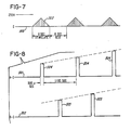
- Stimulator 50 generates a first signal 301 as illustrated by the top line of Fig. 8 and a second signal 302 as illustrated by the bottom line of Fig. 8.
- Signal 301 is applied across terminals 15a and 15c, while signal 302 is applied terminals 15b and 15c.
- Terminal 15c is connected to high voltage ground, as hereinafter described with reference to Fig. 5.
- Each of signals 301 and 302 has an envelope generally illustrated by triangular projections 303 rising above the line 300 of Fig. 7.
- the signal is characterized by alternating stimulation and rest periods of approximately 6 seconds each.
- the signal is pulsed at a frequency in a range from about 55 to 65 Hz and preferably about 60 Hz.
- the pulses which are so generated have peak values which increase gradually from a value near 0 volts to a maximum which is somewhat less than 255 volts and which produces maximum effort from the muscle or muscle group being stimulated. Thereafter the pulse amplitudes decrease gradually to a value near zero, and the muscle is rested.
- the maximum voltage value depends upon the state of exhaustion of the muscle and the effort which is desired. As the muscle tires, more stimulation voltage is required for production of the same effort. Generally speaking a maximum voltage of about 255 volts produces recruitment of all motor units and results in maximum effort by the muscle.
- signal 301 comprises a series of pulses 304 while signal 302 comprises another series of pulses 305.
- Pulses 304 and 305 are generated in an alternating sequence at a frequency of 60 Hz each. Thus the effective combined frequency is 120 Hz.
- Pulses 304 and 305 have peak values which conform with the signal envelope of Fig. 7. They have a duration of approximately 500 microseconds, so that each of signals 301 and 302 has a duty cycle of 0.03. It has been found that if the pulse width is increased, then the stimulation voltage may be decreased and vice versa.
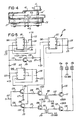
- the circuitry for producing signals 301 and 302 is illustrated in Fig. 5.
- the associated feedback and control circuitry is illustrated schematically in Fig. 6.
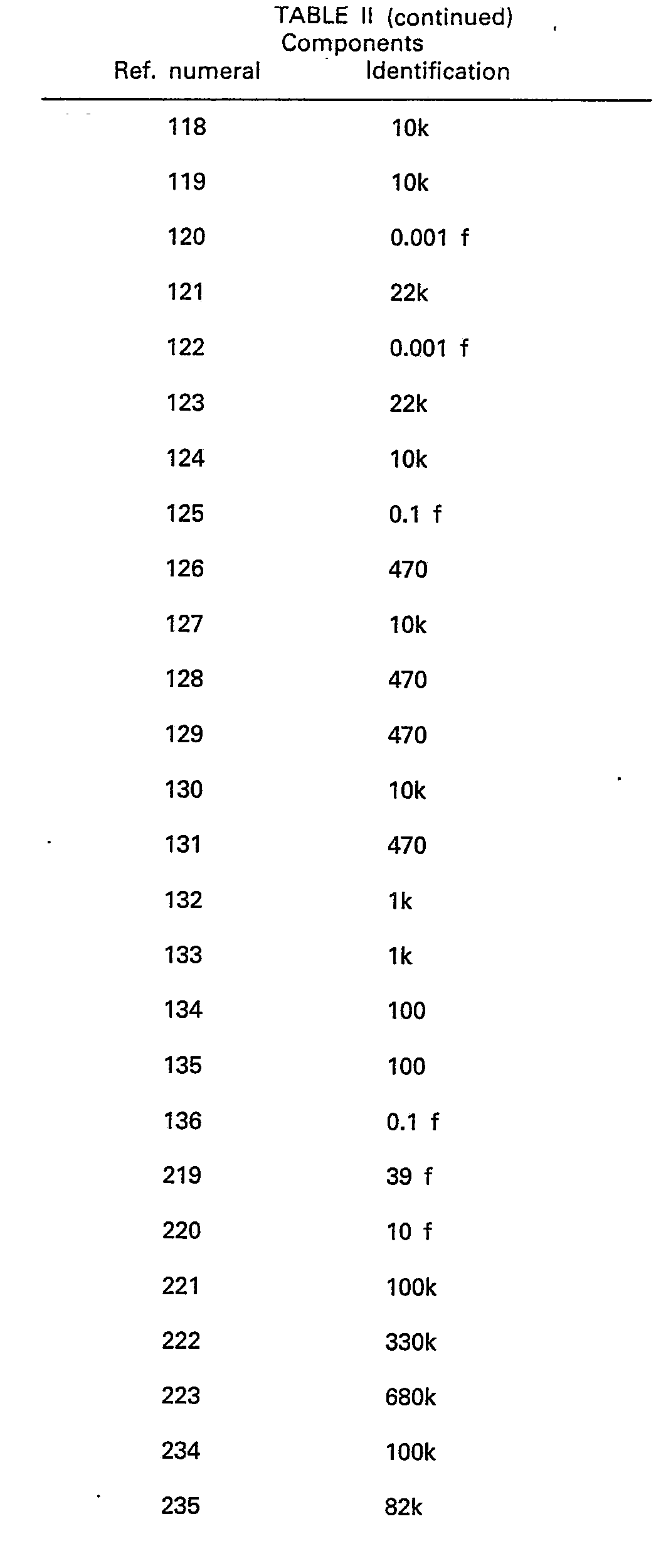
- the circuitry includes integrated circuits as identified in Table I and components as identified in Table II. Table III lists significant pin number designations for the principal integrated circuits listed in Table I.
- IC 101 is connected to operate as a 60 Hz free running multivibrator.
- the output from IC 101 is applied via transistor 104 to input pins 2 of IC 102 and 103.
- IC 102 and 103 produce alternating 500 microsecond pulses each at a frequency of 60 Hz for application to the collector terminals of transistors 105 and 106.
- the pulse width is set by appropriate selection of the resistance for resistors R116 and R124 and the capacitance of capacitors 117 and 125, as shown in the manufacturer's data sheets for integrated circuits 102 and 103.
- the phase between the pulses produced by integrated circuits 102 and 103 is set by appropriate selection of the resistance for resistors 113 and 114.
- An analog voltage representing the desired envelope for the stimulation pulses is applied to input line 197, which is connected to the base terminals of transistors 105 and 106.
- output pulses from pin 3 IC of 102 and pin 3 of IC 103 are applied to the collectors of transistors 1'06 and 105 respectively.
- transistors 106 and 105 generate emitter currents across resistors 130 and 127 providing voltage profiles of the general shape illustrated in Figs. 7 and 8. These voltages are applied to the base terminals of transistors 108 and 107. This results in corresponding voltage pulses ranging between 0 and 12 volts across the primary windings of transformers 110 and 109.
- the voltage pulses across the primary windings of transformers 110 and 109 produce low current, high voltage pulses ranging from 0 to 255 volts across the secondary windings of transformers 110 and 109.
- the secondary windings of transformers 110 and 109 have one side grounded to a high voltage ground which is different from the ground utilized for the primary windings thereof.
- the output pulses from the secondary windings are thereby RF isolated to maintain the safety of the person who is the subject of the exercise procedure.
- Output voltage pulses from transformers 110 and 109 are applied to the base terminals of transistors 112 and 111 respectively.
- Transistors 112 and 111 provide a current gain so as to have high current, high voltage and low duty cycle pulses available for application across terminal pairs 15a-15c and 15b-15c.
- the analog driving signal appearing at line 197 is generated by the control system circuitry as illustrated in Fig. 6.
- the heart of the control system is the computer 13, which in the embodiment described herein is an Apple II computer sold by Apple Computer Inc. of Cupertino, California.
- the Apple II computer is provided with several slots into which may be plugged connectors for customized peripheral devices.
- the system described herein is plugged into slot number 3, which includes a connector 200 as illustrated by dotted lines in Fig. 6.
- the computer addresses analog to digital converter 12 and digital to analog computer 13 through a decoder/demultiplexer 201.
- the peripheral board is addressed by the computer in memory locations C100 to C1 FF (hexadecimal notation).
- Pin number 1 of connector 200 provides a signal from the computer's input/output select line. This line becomes active whenever one of the memory locations C1 FF to C100 are selected for memory read or write operations.
- Pin number 1 is tied to pin number 5 of IC 201, an SN74LS138 integrated circuit.
- Pin number 5 is the G2 input of IC 201.
- a signal at this terminal enables IC 201 to decode the three high order bits (A7, A6, and A5) of an eight-bit address provided by the computer. These three bits appear at pin numbers 9, 8 and 7 respectively of connector 200.
- IC 201 is designed for producing eight decoded outputs, but only three of these outputs are used. These outputs appear at pin numbers 14, 12 and 10 and respectively read A/D converter 12, strobe D/A converter 14 and strobe A/D converter 12.
- A/D converter 12 is an eight channel device sold by National Semiconductor under the designation ADC0808. A/D converter 12 receives its clock from the system clock on pin number 40 of connector 200.
- A/D converter 12 When a strobe signal appears at pin number 12 of IC 201, A/D converter 12 is enabled for reading and digitizing analog signals appearing at any one of eight analog input ports (only two of which are used). The two analog input ports are addressed by a three-bit address appearing at pin numbers 25, 24 and 23 of A/D converter 12. The three address bits are the three least significant bits of an eight-bit address generated by computer 13. These three bits appear at pin numbers 2, and 4 of connector 200 (the three most significant bits appearing at pin numbers 7, 8 and 9 as above stated and bit numbers 3 and 4 not being utilized.
- Computer 13 generates the above mentioned eight-bit address whenever any one of computer memory address locations 50080 to 50087 (decimal notation) are strobed. Such strobing not only generates an associated eight-bit address, but also enables A/D converter 12 by causing generation of a strobe signal at output pin 12 of IC201, as above described.
- Memory locations 50080 to 50087 are strobed by execution of a "POKE" instruction, such as, for instance, the instruction "POKE 50080,0" appearing at line number 1450 of the computer program set forth in Table IV hereof.
- the described embodiment supplies only two analog input signals for digitizing by A/D converter 12. These two signals appear at pin numbers 3 and 28 of A/D converter 12 and are addressed respectively by "POKING" memory locations 50080 and 50082 respectively.
- the resulting digitized representation thereof appears in eight-bit format at pin numbers 17,14,15,8,18,19,20 and 21 of A/D converter 12. These eight bits are read into memory location 49952 (decimal notation) upon execution of a "PEEK" instruction.
- A/D converter 12 is strobed to start conversion of the analog signal to digital format.
- a maximum of 100 microseconds is required for the analog to digital conversion, after which the computer may execute a normal memory read cycle, whereby the digitized data is transferred onto the data bus and stored in memory location 49952.
- the output of A/D converter 12 is an eight-bit binary signal ranging between values of 0 and 255 (decimal) for analog input voltages between 0 and 5 volts.
- the analog signal supplied to pin No. 3 of A/D converter 12 has a triangular voltage profile and is produced by a profile generating circuit 202, comprising IC 204, amplifier 209, capacitors 219 and 220, and resistors 219 through 223.
- IC 204 generates a square wave at 1/6 Hz which is converted to a triangular ramp by capacitor 219 and resistor 221 and is buffered by amplifier 209.
- the triangular voltage profile, so generated, represents a desired response from potentiometer 17 when the leg of the subject is being stimulated to raise and lower.
- potentiometer 17 is applied to pin No. 28 of A/D converter 12, as shown in Fig. 6.
- An output-of 5 volts from potentiometer 17 represents a shaft angle rotation of 360°.
- the diameter of roller 38 is selected such that one rotation thereof corresponds to a leg movement of about 70 degrees from its initial vertical position.
- the amplitude of the analog stimulation signal appearing at line 197 is controlled by D/A converter 14, a DAC0831 integrated circuit sold by National Semiconductor. D/A converter 14 is selected for operation by applying a strobe signal to pin 19 thereof. Also, a write signal (logic LO) is applied to input terminals 1 and 2 for activating the transfer of data to the internal latch register of D/A converter 14. The data so transferred is an eight-bit stimulation command code appearing at terminals 13, 14, 15, 16, 4, 5, 6 and 7 of D/A converter 14. The output of D/A converter 14 is buffered and amplified and thereafter applied to input line 197 of stimulator 50.
- Computer 13 generates eight-bit binary representation of stimulation command voltages ranging between 0 and 255 by executing an appropriate POKE instruction.
- a desired stimulation voltage ranging between 0 and 255 is POKED into memory location 50016 (decimal).
- the computer When this memory location is POKED the computer generates an address for IC201 which causes output pin 12 to go LO.
- This LO output signal is inverted by inverter 205 to create the above mentioned strobe signal for D/A converter 14.
- the program set forth in Table IV includes an isometric strength measurement routine beginning at line 220 and a main control program beginning at line 1000.
- the main control program includes a start cycle beginning at line 1250 and a muscle stimulation routine beginning at line 1432.
- the start cycle finds the beginning of a ramp generated by the profile generator 202.
- the computer increments a variable Y from 1 to 17 (line 290) and POKES the value 10Y into memory location 50016. This causes generation of stimulation pulses having a voltage equal to the value 10Y.
- the test supervisor depresses the Escape key on the computer control board. This action loads the ASCII code 155 into memory location 49152.
- the computer checks that memory location at line 329 and jumps to line 400 if the Escape key has been depressed.
- the computer assigns the current value of 10Y to the variable Z as a threshold voltage.
- the computer enters the main control program to determine the maximum strength of the muscle by isokinetic exercise. During this routine the computer steps the stimulation voltage from the value Z up to 255 volts in 10 volt steps (lines 1045 and 1060). During this period of time the leg is attached to cable 34 as indicated by Fig. 3. When strength meter 36 indicates that the strength has levelled off, then the test supervisor again depresses the Escape key. The computer checks memory location 49152 once during each voltage step (line 1105) and proceeds to line 1120, if the Escape key has been depressed.
- the isokinetic exercise routine begins at line 1432. During this routine the computer generates stepped variations for a variable Z9 and POKES the value of Z9 into memory location 50016. After each new value of Z9 has been utilized for generation of a corresponding stimulation voltage, the computer checks to see if Z9 has a value equal to 255 (maximum stimulation voltage). If that value is noted, than the isokinetic exercise routine is terminated. If not, the computer proceeds to execute the instructions at line 1450 which cause reading of the analog voltages generated by profile generator 202 and potentiometer 17. These voltages are digitized and utilized to establish values for variables A8 and A9 respectively.
- A8 is greater than A9, the computer knows that the leg is not raised as much as it should be, and the value of Z9 is increased. This then increases the stimulation voltage command generated by the computer. Conversely, if A8 is less than A9, Z9 and the stimulation command are decreased. When A8 has decreased to a value indicating the end of a cycle, then the leg is rested for the duration of a counting loop which continues for approximately 6 seconds.
- Stimulation signals of the general type herein described may be applied (at greatly reduced voltage levels) to implanted sleeve electrodes which surround the motoneurons as described in the Petrofsky article.
- the apparatus and/or methods could be used to drive self-propelled vehicles, i.e. the muscle stimulation or contraction, and in particular the resultant limb movement, could be used to operate pedals or other drivable members of a tricycle, bicycle, self-propelled wheel chair or other device, and/or to carry out control functions associated with such devices.
- the resultant limb movement could be used to operate or control equipment, or to enable, or assist in enabling, a person to walk or carry out other normal limb functions.
Landscapes
- Health & Medical Sciences (AREA)
- Physical Education & Sports Medicine (AREA)
- Engineering & Computer Science (AREA)
- Biomedical Technology (AREA)
- Nuclear Medicine, Radiotherapy & Molecular Imaging (AREA)
- Radiology & Medical Imaging (AREA)
- Life Sciences & Earth Sciences (AREA)
- Animal Behavior & Ethology (AREA)
- General Health & Medical Sciences (AREA)
- Public Health (AREA)
- Veterinary Medicine (AREA)
- Electrotherapy Devices (AREA)
- Feedback Control In General (AREA)
Description
- The present invention relates to a method and apparatus for electrically stimulating muscle and, more particularly, to a computer controlled method and apparatus for monitoring muscular activity and adjusting an electrical stimulus to provide controlled and sustained isokinetic contractions. Still more particularly the present invention relates to a method and apparatus for directing coordinated movement of several muscles and exercising them through a specific exercise routine.
- The invention which is disclosed and claimed herein has particular value in the treatment of persons who have suffered injuries resulting in spinal cord damage. This particular type of damage often times produces partial or total paralysis of muscles which are controlled from a point below the point of spinal cord damage. The victim then faces a life of relative inactivity and deterioration of muscles which otherwise would be active. It has now been found that such muscles can be stimulated to engage in an exercise program once thought to be impossible. Moreover, it has been found that such an exercise program can restore normal muscle tone, even after years of inactivity.
- Since the work of Galvani in 1791, it has been known that electricity can be used to induce muscle contractions. Recently, there has been increased awareness of the value of electrostimulation in muscle therapy.
- Numerous devices and techniques have been developed for supplying electrical pulses as part of a therapeutic regime of muscle stimulation. Several examples of these are found in the patent literature.
- Frank, U.S. Patent No. 3,204,637 (1965) discloses a stimulating apparatus for the functional stimulation of muscles lacking normal voluntary control in which a pulse train having adjustable characteristics is generated and applied to a pair of electrodes adapted to be connected to the nerve trunk or muscle to be stimulated.
- Radwan, U.S. Patent No. 3,387,147 (1968) discloses a muscle stimulating pulse generator designed to provide a pulse signal having a relatively high voltage-to-width ratio and a steep rising wavefront.
- Maurer, U.S. Patent No. 3,817,254 (1974), discloses a transcutaneous stimulator for use in suppressing pain designed to differentially stimulate touch versus pain nerve fibres in an effort to reduce the prickly sensation known to accompany some pain therapy. Maurer notes that differences in the response of nerves to electro-stimulation can be used to selectively stimulate different types of nerves. According to Maurer, nerve fibers are distinguished in terms of their size and conduction velocity. He notes that the amplitude of electrical stimulation required to elicit a muscle response increases as the fiber size decreases.
- Nawracaj et al, U.S. Patent No. 4,071,033 (1978), discloses an electrostimulation device which utilizes a heterodyne effect to produce an otherwise painful low frequency stimulus in a muscle and cause the muscle to contract and relax at a low frequency.
- Wyss et al, U.S. Patent No. 4,148,321 (1979), discloses a muscular therapy similar in some respects to Nawracaj et al wherein muscles are made to rhythmically contract and relax at a very low frequency which is induced by modulating a medium frequency current between 3,000 and 100,000 Hz with a low frequency current less than 1 Hz. In one embodiment Wyss et al uses a phase shifter to transform the modulated alternating output current into a three phase alternating current, which is delivered to three electrodes angularly spaced about a limb to provide deep uniform stimulation.
- Kofskey et al, U.S. Patent No. 4,177,819 (1979) teaches an apparatus for stimulating a muscle for 2 to 20 seconds at 2 to 50 second intervals using a 2000 to 3000 Hz signal modulated at 40 to 50 Hz. In one embodiment, the muscle stimulating waveform is controlled by a microprocessor which gradually increases and decreases the amplitude of the stimulation at the beginning and end of each pulse. The microprocessor responds to signals from a no-load/overload sensor and to a manually controlled gain setting signal.
- It can be seen that the efforts embodied in the foregoing patents focus on the stimulus itself as the therapeutic agent and have as a principal objective to optimize the intensity, duration and frequency of the stimulus to enhance its therapeutic effects. In the disclosed therapies, the muscle is not stimulated against a load. These prior art systems do not provide smooth isometric contractions and do not respond to muscle activity.
- In order to train a muscle and make it physically strong, it is necessary to work the muscle against a load while producing powerful, sustained, isokinetic contractions at a substantial proportion of the muscle's strength. Isokinetic contractions cannot be maintained for prolonged periods of time in the aforementioned therapies, because they stimulate the muscle synchronously using frequencies much higher than normal physiological frequencies. This causes the muscle to fatigue rapidly, making it impossible to maintain muscle tension.
- Petrofsky, "Microprocessor Controlled Stimulation in Paralyzed Muscle", IEEE August 1979 outlines a computer-controlled stimulation system which mimics normal asynchronous recruitment of motor units and firing rate control in the gastrocnemius muscle of a cat. A computer was programmed to set the recruitment order of the motor units as it sensed fatigue in the muscle. This was accomplished by using an anodal block electrode in combination with a sequential electrode sleeve. The electrode sleeve was placed around the motor nerve to the muscle and was configured for alternately stimulating three groups of neurons in the nerve. The anodal block electrode was placed just proximal to the muscle. Muscle fatigue was sensed by a strain gauge transducer mounted on a bar attached to one end of the muscle.
- The Petrofsky article teaches that electrostimulation can be controlled by a microprocessor in such a way as to develop isometric contractions in a muscle. However, there is no teaching of any method or apparatus for causing smooth, natural isokinetic contractions. Also, the techniques taught by Petrofsky are not applied to man.
- It is an object of the present invention to provide a method and apparatus for electrically stimulating a muscle and exercising the muscle through a specific exercise routine based upon feedback control.
- From one aspect the invention provides apparatus for stimulating muscular activity in a paralyzed human limb comprising control means for generating a stimulation control signal, stimulation means responsive to said control signal for generating a series of stimulation signals and electrode means for applying said stimulation signals to a control muscle for said limb; characterised in that said control means comprise feedback means (17) responsive to motion of said limb for generating a corresponding feedback signal and computing means (12, 13, 14) responsive to said feedback signal for generating said stimulation control signal; said stimulation means comprise pulse generating means (101, 102, 103) for causing said stimulation signals to be generated as a pair of pulse trains, the pulses in one train alternating with those of the other train; and said electrode means comprise at least three electrodes (15a, 15b, 15c) connected in pairs for alternate energisation by said pulse trains.
- From another aspect the invention provides a method of causing movement of a paralyzed human limb (the method not being one for treatment or diagnosis) comprising the steps of generating a stimulation control signal, generating electrical stimulation signals in response to said control signal and applying said stimulation signals to a muscle connected for producing movement of said limb; characterised in that said control signal is varied by generating a feedback signal corresponding to the motion of said limb and said control signal is adjusted in accordance with variations in said feedback signal; said stimulation signals comprising a pair of pulse trains, the pulses in one train alternating with those of the other train, and are applied to the muscle through at least three electrodes connected in pairs for alternate energisation by the pulse trains.
- In the preferred embodiment the stimulation apparatus is controlled through a digital to analog converter by a digitally controlled microprocessor. The limb which is moved by the stimulated muscle is secured against a dynamic load which yieldingly resists movement of the muscle. A feedback sensor senses the movement actually achieved by the limb and transmits an indication thereof through an analog to digital converter back to the microprocessor.
- In an exercise routine, a plurality of transcutaneous stimulators are applied to the skin of the subject in a pattern for stimulating a muscle which is connected for moving the limb to be exercised. The stimulators are then excited by a plurality of stimulation signals having profiles for causing the muscle to contract and produce a predetermined movement of the limb. While the limb is contracting, a resisting force is applied thereagainst to cause exertion of the muscle during its contraction. The movement of the limb is sensed and a corresponding feedback signal is generated. The feedback signal is monitored to determine when a predetermined movement has been achieved. After the predetermined movement has been achieved, the stimulation signals are altered to permit the limb to return to its initial position. The process is then repeated to produce an exercise routine.
- In order that the invention may be more readily understood, reference will now be made to the accompanying drawings, in which:
- Fig. 1 is a schematic illustration of exercising apparatus in accordance with the present invention;
- Fig. 2 is a side elevation view of an exercise chair;
- Fig. 3 is an illustration of means for indicating the isometric load developed by a human leg;
- Fig. 4 is a view taken along line 4-4 of Fig. 2;
- Fig. 5 is a schematic illustration of a stimulation apparatus;
- Fig. 6 is a schematic illustration of a control system for the stimulation apparatus of Fig. 5;
- Fig. 7 is a schematic illustration of a stimulation signal; and
- Fig. 8 is an enlarged schematic illustration of portions of two alternately pulsed stimulation signals.
- Fig. 1 illustrates apparatus comprising an
exercise system 10, constructed in accordance with this invention. The exercise system may comprise achair 16 mounted on asupport frame 11.Chair 16 rests upon asupport board 30 and is clamped in place by aclamp plate 28, as illustrated in Fig. 2.Clamp plate 28 may be forced upwardly against the lower surface ofsupport board 30 by any convenient means, such as, for instance, a rotary handle andscrew arrangement 29. Whenclamp 28 is releasedchair 16 may be moved along the surface ofsupport board 30 as illustrated by thearrow 45. This enables positioning ofchair 16 for accommodating an exercise routine for either the left leg or the right leg of a person seated inchair 16. -
Exercise system 10 also comprises aseat belt 18 for securing a person inchair 16 and aleg strap 19 for grasping the lower portion of aleg 31.Leg strap 19 is provided with interlocking pieces of hook andloop fastening fabric leg strap 19 be easily and securely fastened around a leg of any size. -
Leg strap 19 has a steel eyelet for fastening to one or the other of a pair of scissor-type eyelet fasteners Fasteners cables board 24. -
Cables roller 23 having a pair of offset guide channels (not illustrated).Cable 33 extends rearwardly fromroller 23 around aroller 36 and thence upwardly for attachment to atoothed belt 35.Cable 34 wraps aroundroller 23 and extends upwardly for attachment to a relativelystiff bending arm 25 supported uponframe member 39, as best illustrated in Fig. 3. -
Toothed belt 35 extends around a pair oftoothed rollers support plates 41 a and 41 b, as best illustrated in Fig. 4.Support plates 41 a and 41 b are securely supported by frame member 40, which in turn is supported byframe member 39. -
Belt 35 supports a set ofweights 27 placed upon apan 42. Thus when theleg 31 moves arcuately as indicated byarrow 46, theweights 27 are raised or lowered. The arrangement provides a dynamic load which resists but does not prevent movement ofleg 31. - When the
leg 31 is extended upwardly, pullingcable 33 andbelt 35, the movement is measured by a potentiometer 17 (see Fig. 4) attached toroller 38 by a coupling device 44'. The housing forpotentiometer 17 is supported by a support arm 43 secured to the upper support plate 41, as viewed in Fig. 4. - As the
leg 31 moves and pullsbelt 35 acrossroller 38, thepotentiometer 17 transmits a feedback signal to A/D converter 12. A/D converter 12 converts the feedback signal into a digital format for processing bycomputer 13, as hereinafter described in detail.Computer 13 responds to the feedback signal by transmitting a digital control signal to D/A converter 14. D/A converter 14 then generates an analog stimulation signal forstimulator 50.Stimulator 50 uses the control signal from D/A converter 14 for generation of a pair of stimulation signals which are applied acrosselectrodes Electrodes - For an exercise as hereinafter described the electrodes are placed in spaced positions above the quadriceps muscles of one leg, as generally illustrated in Fig. 2. The electrodes are attached to the leg of the subject by hypoallergenic tape or elastic bandages. Priorto application of the electrodes, the skin is cleaned and dried. An electrode gel, such as Tens electrode gel, also sold by Medtronic, Inc. is applied to the electrodes before they are placed upon the skin of the subject.
- When the stimulation signals from
stimulator 50 are applied toelectrodes leg 31 against the dynamic resistance ofcable 33 as described above. Alternatively,leg strap 19 may be connected tocable 34 in which 'case leg 31 strains isometrically against bendingarm 25. This produces an output signal from astrain gauge 32 mounted on top of bendingarm 25.Strain gauge 32 is connected to provide a load signal for ameter 26 which may be mounted at any convenient location. Themeter 26 provides a "strength" indication for use in the exercise procedure hereinafter described in detail. - The stimulation signals which are applied to
electrodes Stimulator 50 generates afirst signal 301 as illustrated by the top line of Fig. 8 and a second signal 302 as illustrated by the bottom line of Fig. 8.Signal 301 is applied acrossterminals terminals - Each of
signals 301 and 302 has an envelope generally illustrated bytriangular projections 303 rising above theline 300 of Fig. 7. The signal is characterized by alternating stimulation and rest periods of approximately 6 seconds each. During the stimulation period the signal is pulsed at a frequency in a range from about 55 to 65 Hz and preferably about 60 Hz. The pulses which are so generated have peak values which increase gradually from a value near 0 volts to a maximum which is somewhat less than 255 volts and which produces maximum effort from the muscle or muscle group being stimulated. Thereafter the pulse amplitudes decrease gradually to a value near zero, and the muscle is rested. The maximum voltage value depends upon the state of exhaustion of the muscle and the effort which is desired. As the muscle tires, more stimulation voltage is required for production of the same effort. Generally speaking a maximum voltage of about 255 volts produces recruitment of all motor units and results in maximum effort by the muscle. - As shown in Fig. 8, signal 301 comprises a series of
pulses 304 while signal 302 comprises another series ofpulses 305.Pulses Pulses signals 301 and 302 has a duty cycle of 0.03. It has been found that if the pulse width is increased, then the stimulation voltage may be decreased and vice versa. - The circuitry for producing
signals 301 and 302 is illustrated in Fig. 5. The associated feedback and control circuitry is illustrated schematically in Fig. 6. The circuitry includes integrated circuits as identified in Table I and components as identified in Table II. Table III lists significant pin number designations for the principal integrated circuits listed in Table I.


- The operation of
stimulator 50 will now be described with reference to Fig. 5. That figure shows 3integrated circuits transistor 104 to inputpins 2 ofIC IC transistors capacitors 117 and 125, as shown in the manufacturer's data sheets forintegrated circuits integrated circuits resistors - An analog voltage representing the desired envelope for the stimulation pulses is applied to input
line 197, which is connected to the base terminals oftransistors pin 3 IC of 102 andpin 3 ofIC 103 are applied to the collectors of transistors 1'06 and 105 respectively. As aresult thereof transistors resistors transistors transformers - The voltage pulses across the primary windings of
transformers transformers transformers - Output voltage pulses from
transformers transistors 112 and 111 respectively.Transistors 112 and 111 provide a current gain so as to have high current, high voltage and low duty cycle pulses available for application acrossterminal pairs 15a-15c and 15b-15c. The analog driving signal appearing atline 197 is generated by the control system circuitry as illustrated in Fig. 6. - The heart of the control system is the
computer 13, which in the embodiment described herein is an Apple II computer sold by Apple Computer Inc. of Cupertino, California. The Apple II computer is provided with several slots into which may be plugged connectors for customized peripheral devices. The system described herein is plugged intoslot number 3, which includes a connector 200 as illustrated by dotted lines in Fig. 6. The computer addresses analog todigital converter 12 and digital toanalog computer 13 through a decoder/demultiplexer 201. The peripheral board is addressed by the computer in memory locations C100 to C1 FF (hexadecimal notation).Pin number 1 of connector 200 provides a signal from the computer's input/output select line. This line becomes active whenever one of the memory locations C1 FF to C100 are selected for memory read or write operations.Pin number 1 is tied to pinnumber 5 ofIC 201, an SN74LS138 integrated circuit.Pin number 5 is the G2 input ofIC 201. A signal at this terminal enablesIC 201 to decode the three high order bits (A7, A6, and A5) of an eight-bit address provided by the computer. These three bits appear atpin numbers -
IC 201 is designed for producing eight decoded outputs, but only three of these outputs are used. These outputs appear atpin numbers D converter 12, strobe D/A converter 14 and strobe A/D converter 12. A/D converter 12 is an eight channel device sold by National Semiconductor under the designation ADC0808. A/D converter 12 receives its clock from the system clock on pin number 40 of connector 200. - When a strobe signal appears at
pin number 12 ofIC 201, A/D converter 12 is enabled for reading and digitizing analog signals appearing at any one of eight analog input ports (only two of which are used). The two analog input ports are addressed by a three-bit address appearing atpin numbers D converter 12. The three address bits are the three least significant bits of an eight-bit address generated bycomputer 13. These three bits appear atpin numbers pin numbers bit numbers -
Computer 13 generates the above mentioned eight-bit address whenever any one of computer memory address locations 50080 to 50087 (decimal notation) are strobed. Such strobing not only generates an associated eight-bit address, but also enables A/D converter 12 by causing generation of a strobe signal atoutput pin 12 of IC201, as above described. Memory locations 50080 to 50087 are strobed by execution of a "POKE" instruction, such as, for instance, the instruction "POKE 50080,0" appearing at line number 1450 of the computer program set forth in Table IV hereof. - As mentioned above, the described embodiment supplies only two analog input signals for digitizing by A/
D converter 12. These two signals appear atpin numbers D converter 12 and are addressed respectively by "POKING" memory locations 50080 and 50082 respectively. The resulting digitized representation thereof appears in eight-bit format atpin numbers D converter 12. These eight bits are read into memory location 49952 (decimal notation) upon execution of a "PEEK" instruction. - It is therefore seen that when memory addresses 50080 through 50087 are strobed, the computer selects the analog channel which is to be multiplexed into A/
D converter 12. Simultaneously with this selection A/D converter 12 is strobed to start conversion of the analog signal to digital format. A maximum of 100 microseconds is required for the analog to digital conversion, after which the computer may execute a normal memory read cycle, whereby the digitized data is transferred onto the data bus and stored in memory location 49952. It is to be noted that the output of A/D converter 12 is an eight-bit binary signal ranging between values of 0 and 255 (decimal) for analog input voltages between 0 and 5 volts. - The analog signal supplied to pin No. 3 of A/
D converter 12 has a triangular voltage profile and is produced by aprofile generating circuit 202, comprisingIC 204,amplifier 209,capacitors resistors 219 through 223.IC 204 generates a square wave at 1/6 Hz which is converted to a triangular ramp bycapacitor 219 andresistor 221 and is buffered byamplifier 209. The triangular voltage profile, so generated, represents a desired response frompotentiometer 17 when the leg of the subject is being stimulated to raise and lower. - The output of
potentiometer 17 is applied to pin No. 28 of A/D converter 12, as shown in Fig. 6. An output-of 5 volts frompotentiometer 17 represents a shaft angle rotation of 360°. The diameter ofroller 38 is selected such that one rotation thereof corresponds to a leg movement of about 70 degrees from its initial vertical position. - The amplitude of the analog stimulation signal appearing at
line 197 is controlled by D/A converter 14, a DAC0831 integrated circuit sold by National Semiconductor. D/A converter 14 is selected for operation by applying a strobe signal to pin 19 thereof. Also, a write signal (logic LO) is applied to inputterminals A converter 14. The data so transferred is an eight-bit stimulation command code appearing atterminals A converter 14. The output of D/A converter 14 is buffered and amplified and thereafter applied to inputline 197 ofstimulator 50. -
Computer 13 generates eight-bit binary representation of stimulation command voltages ranging between 0 and 255 by executing an appropriate POKE instruction. A desired stimulation voltage ranging between 0 and 255 is POKED into memory location 50016 (decimal). When this memory location is POKED the computer generates an address for IC201 which causesoutput pin 12 to go LO. This LO output signal is inverted byinverter 205 to create the above mentioned strobe signal for D/A converter 14. - The computer program for producing the above described operation is described in the program listing set forth in Table IV. This program is written in source code in accordance with the APPLESOFT variation of the well known BASIC language. The program will be self-explanatory to persons skilled in the art and only brief comments need be made.
- The program set forth in Table IV includes an isometric strength measurement routine beginning at
line 220 and a main control program beginning at line 1000. The main control program includes a start cycle beginning at line 1250 and a muscle stimulation routine beginning at line 1432. The start cycle finds the beginning of a ramp generated by theprofile generator 202. - During the isometric measurement routine the computer increments a variable Y from 1 to 17 (line 290) and POKES the value 10Y into memory location 50016. This causes generation of stimulation pulses having a voltage equal to the value 10Y. When the muscle begins to develop tension, then the test supervisor depresses the Escape key on the computer control board. This action loads the ASCII code 155 into memory location 49152. The computer checks that memory location at line 329 and jumps to
line 400 if the Escape key has been depressed. The computer then assigns the current value of 10Y to the variable Z as a threshold voltage. - After the threshold voltage has been established, the computer enters the main control program to determine the maximum strength of the muscle by isokinetic exercise. During this routine the computer steps the stimulation voltage from the value Z up to 255 volts in 10 volt steps (lines 1045 and 1060). During this period of time the leg is attached to
cable 34 as indicated by Fig. 3. Whenstrength meter 36 indicates that the strength has levelled off, then the test supervisor again depresses the Escape key. The computer checks memory location 49152 once during each voltage step (line 1105) and proceeds to line 1120, if the Escape key has been depressed. - After the maximum strength has been determined, the computer looks for a start of a cycle (line 1250).
- The isokinetic exercise routine begins at line 1432. During this routine the computer generates stepped variations for a variable Z9 and POKES the value of Z9 into memory location 50016. After each new value of Z9 has been utilized for generation of a corresponding stimulation voltage, the computer checks to see if Z9 has a value equal to 255 (maximum stimulation voltage). If that value is noted, than the isokinetic exercise routine is terminated. If not, the computer proceeds to execute the instructions at line 1450 which cause reading of the analog voltages generated by
profile generator 202 andpotentiometer 17. These voltages are digitized and utilized to establish values for variables A8 and A9 respectively. - If A8 is greater than A9, the computer knows that the leg is not raised as much as it should be, and the value of Z9 is increased. This then increases the stimulation voltage command generated by the computer. Conversely, if A8 is less than A9, Z9 and the stimulation command are decreased. When A8 has decreased to a value indicating the end of a cycle, then the leg is rested for the duration of a counting loop which continues for approximately 6 seconds.
- It will be appreciated that the muscular response produced by the invention herein described is not limited to the use of transcutaneous stimulators. Stimulation signals of the general type herein described may be applied (at greatly reduced voltage levels) to implanted sleeve electrodes which surround the motoneurons as described in the Petrofsky article.
- While the method herein described and the form of apparatus for carrying this method into effect constitutes preferred embodiments of this invention, it is to be understood that the invention is not limited to this precise method and form of apparatus, and that changes may be made in either without departing from the scope of the invention which is defined in the appended claims.


- The apparatus described and claimed are not limited to therapeutic applications. For example, the apparatus and/or methods could be used to drive self-propelled vehicles, i.e. the muscle stimulation or contraction, and in particular the resultant limb movement, could be used to operate pedals or other drivable members of a tricycle, bicycle, self-propelled wheel chair or other device, and/or to carry out control functions associated with such devices. Additionally or alternatively, the resultant limb movement could be used to operate or control equipment, or to enable, or assist in enabling, a person to walk or carry out other normal limb functions.
Claims (12)
Applications Claiming Priority (2)
| Application Number | Priority Date | Filing Date | Title |
|---|---|---|---|
| US417934 | 1982-09-14 | ||
| US06/417,934 US4492233A (en) | 1982-09-14 | 1982-09-14 | Method and apparatus for providing feedback-controlled muscle stimulation |
Publications (2)
| Publication Number | Publication Date |
|---|---|
| EP0103491A1 EP0103491A1 (en) | 1984-03-21 |
| EP0103491B1 true EP0103491B1 (en) | 1987-06-16 |
Family
ID=23655958
Family Applications (1)
| Application Number | Title | Priority Date | Filing Date |
|---|---|---|---|
| EP83305389A Expired EP0103491B1 (en) | 1982-09-14 | 1983-09-14 | Method and apparatus for providing feedback-controlled muscle stimulation |
Country Status (5)
| Country | Link |
|---|---|
| US (1) | US4492233A (en) |
| EP (1) | EP0103491B1 (en) |
| JP (1) | JPS59146664A (en) |
| CA (1) | CA1234603A (en) |
| DE (1) | DE3372074D1 (en) |
Families Citing this family (63)
| Publication number | Priority date | Publication date | Assignee | Title |
|---|---|---|---|---|
| JPS59160455A (en) * | 1983-03-03 | 1984-09-11 | 半田 康延 | Apparatus for restoring paralyzed upper arm function of heavy limb paralyzed patient by upper motion nerve obstacle |
| WO1985000256A1 (en) * | 1983-06-27 | 1985-01-17 | The Commonwealth Of Australia | Squelch circuit |
| US4620543A (en) * | 1984-06-15 | 1986-11-04 | Richards Medical Company | Enhanced fracture healing and muscle exercise through defined cycles of electric stimulation |
| JPS61217174A (en) * | 1985-03-22 | 1986-09-26 | 新技術事業団 | System for reproducing living body function by functional electric stimulation |
| US4697808A (en) * | 1985-05-16 | 1987-10-06 | Wright State University | Walking assistance system |
| US4811742A (en) * | 1985-06-11 | 1989-03-14 | Verimed, Inc. | Proportional response electrical muscle stimulation |
| US4686991A (en) * | 1985-06-17 | 1987-08-18 | Minnesota Mining And Manufacturing Company | Electrical stimulator for biological tissue utilizing linear current output circuit |
| GB8520473D0 (en) * | 1985-08-15 | 1985-09-18 | Grenfell H W | Electrostimulation of muscles |
| US4817628A (en) * | 1985-10-18 | 1989-04-04 | David L. Zealear | System and method for evaluating neurological function controlling muscular movements |
| US4711242A (en) * | 1986-02-18 | 1987-12-08 | Wright State University | Control system for knee joint |
| AU610497B2 (en) * | 1986-05-23 | 1991-05-23 | Trustees Of The University Of Pennsylvania, The | Portable electro-therapy system |
| US4750499A (en) * | 1986-08-20 | 1988-06-14 | Hoffer Joaquin A | Closed-loop, implanted-sensor, functional electrical stimulation system for partial restoration of motor functions |
| US4715367A (en) * | 1986-09-15 | 1987-12-29 | Crossley Robert B | Multifunctional behavioral modification device for snoring, bruxism, and apnea |
| US4742832A (en) * | 1987-02-12 | 1988-05-10 | Richard Kauffmann | Muscle measuring apparatus and method |
| US4848152A (en) * | 1987-05-04 | 1989-07-18 | Pratt Jr G Andrew | Biofeedback lifting monitor |
| US4912638A (en) * | 1987-05-04 | 1990-03-27 | Pratt Jr G Andrew | Biofeedback lifting monitor |
| US4838272A (en) * | 1987-08-19 | 1989-06-13 | The Regents Of The University Of California | Method and apparatus for adaptive closed loop electrical stimulation of muscles |
| US4934368A (en) * | 1988-01-21 | 1990-06-19 | Myo/Kinetics Systems, Inc. | Multi-electrode neurological stimulation apparatus |
| US4969452A (en) * | 1989-03-24 | 1990-11-13 | Petrofsky Research, Inc. | Orthosis for assistance in walking |
| US5054476A (en) * | 1989-03-24 | 1991-10-08 | Petrofsky Research, Inc. | Orthosis for assistance in walking |
| US5163440A (en) * | 1990-05-30 | 1992-11-17 | Trustees Of Boston University | Method for monitoring performance of back muscles |
| US5085226A (en) * | 1990-05-30 | 1992-02-04 | Trustees Of Boston University | Force monitoring apparatus for back muscles |
| US5112296A (en) * | 1991-04-30 | 1992-05-12 | The Board Of Supervisors Of Louisiana State University | Biofeedback activated orthosis for foot-drop rehabilitation |
| US5482051A (en) * | 1994-03-10 | 1996-01-09 | The University Of Akron | Electromyographic virtual reality system |
| US5507788A (en) * | 1994-08-11 | 1996-04-16 | The Regents Of The University Of California | Method and apparatus for controlling skeletal muscle fatigue during electrical stimulation |
| DE19758110B4 (en) * | 1997-12-17 | 2004-07-29 | Biotronik Meß- und Therapiegeräte GmbH & Co. Ingenieurbüro Berlin | Stimulation device for spinal cord stimulation |
| DE19824504C2 (en) * | 1998-06-02 | 2001-08-16 | Albrecht Struppler | Body part stimulation device |
| IL127481A (en) * | 1998-10-06 | 2004-05-12 | Bio Control Medical Ltd | Incontinence treatment device |
| WO2000019939A1 (en) | 1998-10-06 | 2000-04-13 | Bio Control Medical, Ltd. | Control of urge incontinence |
| JP2004505709A (en) * | 2000-08-14 | 2004-02-26 | ネオプラクシス プロプライエタリイ リミテッド | Muscle fatigue meter |
| US7117136B1 (en) * | 2000-08-18 | 2006-10-03 | Linden Research, Inc. | Input and feedback system |
| US6644976B2 (en) | 2001-09-10 | 2003-11-11 | Epoch Innovations Ltd | Apparatus, method and computer program product to produce or direct movements in synergic timed correlation with physiological activity |
| US7280871B2 (en) * | 2001-10-19 | 2007-10-09 | The University Of Syndey | Muscle stimulation systems |
| US20030082884A1 (en) * | 2001-10-26 | 2003-05-01 | International Business Machine Corporation And Kabushiki Kaisha Toshiba | Method of forming low-leakage dielectric layer |
| IL162193A0 (en) * | 2001-11-29 | 2005-11-20 | Biocontrol Medical Ltd | Pelvic disorder treatment device |
| US6862480B2 (en) * | 2001-11-29 | 2005-03-01 | Biocontrol Medical Ltd. | Pelvic disorder treatment device |
| US6712772B2 (en) | 2001-11-29 | 2004-03-30 | Biocontrol Medical Ltd. | Low power consumption implantable pressure sensor |
| US20070185394A1 (en) * | 2004-07-15 | 2007-08-09 | Takashi Ishizuka | Living body optical measurement apparatus |
| US8214047B2 (en) * | 2004-09-27 | 2012-07-03 | Advanced Neuromodulation Systems, Inc. | Method of using spinal cord stimulation to treat gastrointestinal and/or eating disorders or conditions |
| US20070208392A1 (en) * | 2006-02-17 | 2007-09-06 | Alfred E. Mann Foundation For Scientific Research | System for functional electrical stimulation |
| US8195296B2 (en) * | 2006-03-03 | 2012-06-05 | Ams Research Corporation | Apparatus for treating stress and urge incontinence |
| WO2007114875A1 (en) * | 2006-04-04 | 2007-10-11 | Ams Research Corporation | Apparatus for implanting neural stimulation leads |
| US20070265675A1 (en) * | 2006-05-09 | 2007-11-15 | Ams Research Corporation | Testing Efficacy of Therapeutic Mechanical or Electrical Nerve or Muscle Stimulation |
| KR100772908B1 (en) * | 2006-05-15 | 2007-11-05 | 삼성전자주식회사 | Apparatus for supporting muscular movement |
| US20100076254A1 (en) * | 2006-06-05 | 2010-03-25 | Ams Research Corporation | Electrical muscle stimulation to treat fecal incontinence and/or pelvic prolapse |
| US20090012592A1 (en) * | 2006-07-10 | 2009-01-08 | Ams Research Corporation | Tissue anchor |
| US8160710B2 (en) * | 2006-07-10 | 2012-04-17 | Ams Research Corporation | Systems and methods for implanting tissue stimulation electrodes in the pelvic region |
| US20100049289A1 (en) * | 2007-07-10 | 2010-02-25 | Ams Research Corporation | Tissue anchor |
| US9427573B2 (en) | 2007-07-10 | 2016-08-30 | Astora Women's Health, Llc | Deployable electrode lead anchor |
| EP2373220B1 (en) * | 2008-12-05 | 2013-06-19 | Koninklijke Philips Electronics N.V. | Electrical stimulation device for locating an electrical stimulation point |
| US8612010B2 (en) * | 2008-12-23 | 2013-12-17 | Robotic Integrated Technology Development Corporation | Upper extremity muscle therapy system |
| US8615301B2 (en) * | 2008-12-23 | 2013-12-24 | Robotic Integrated Technology Development Corporation | Muscle therapy system |
| US20100217340A1 (en) * | 2009-02-23 | 2010-08-26 | Ams Research Corporation | Implantable Medical Device Connector System |
| US9539433B1 (en) | 2009-03-18 | 2017-01-10 | Astora Women's Health, Llc | Electrode implantation in a pelvic floor muscular structure |
| US8380312B2 (en) * | 2009-12-31 | 2013-02-19 | Ams Research Corporation | Multi-zone stimulation implant system and method |
| IT1397157B1 (en) * | 2010-01-07 | 2013-01-04 | Camerota | MACHINE FOR THE PHYSICAL EXERCISE OF A USER. |
| US9220887B2 (en) | 2011-06-09 | 2015-12-29 | Astora Women's Health LLC | Electrode lead including a deployable tissue anchor |
| US9114255B1 (en) | 2011-06-17 | 2015-08-25 | Customkynetics, Inc. | Exercise device for use with electrical stimulation and related methods |
| EP2753397B1 (en) | 2011-09-08 | 2017-01-11 | AMS Research Corporation | Implantable electrode assembly |
| GB2500641B (en) * | 2012-03-28 | 2016-11-02 | Actegy Ltd | Apparatus for stimulating muscles of a subject |
| GB2500642B (en) * | 2012-03-28 | 2017-02-01 | Actegy Ltd | Apparatus for electrically stimulating muscles of a subject |
| US10857358B2 (en) | 2015-06-02 | 2020-12-08 | Battelle Memorial Institute | Systems for neural bridging of the nervous system |
| US11179251B2 (en) * | 2016-01-08 | 2021-11-23 | Massachusetts Institute Of Technology | Method and system for providing proprioceptive feedback and functionality mitigating limb pathology |
Family Cites Families (32)
| Publication number | Priority date | Publication date | Assignee | Title |
|---|---|---|---|---|
| US1498529A (en) * | 1921-11-21 | 1924-06-24 | James B Allen | Exercising machine |
| US3083712A (en) * | 1961-11-29 | 1963-04-02 | Heinicke Instr Co Inc | Device for producing electrical muscle trerapy |
| US3204637A (en) * | 1963-02-07 | 1965-09-07 | Erich J Frank | Stimulating apparatus |
| US3565080A (en) * | 1964-12-21 | 1971-02-23 | Burroughs Wellcome Co | Neuromuscular block monitoring apparatus |
| US3387147A (en) * | 1967-06-09 | 1968-06-04 | Dynatone Electronics Corp | Muscle stimulating pulse generator |
| GB1227186A (en) * | 1968-09-18 | 1971-04-07 | ||
| DE2101960C3 (en) * | 1971-01-16 | 1979-12-06 | Hugo Sachs Elektronik Kg, 7801 March | Device for measuring biological quantities |
| US3817254A (en) * | 1972-05-08 | 1974-06-18 | Medtronic Inc | Transcutaneous stimulator and stimulation method |
| US4148321A (en) * | 1973-11-26 | 1979-04-10 | Wyss Oscar A M | Apparatuses and methods for therapeutic treatment and active massages of muscles |
| US3888261A (en) * | 1973-12-07 | 1975-06-10 | Medtronic Inc | Time shared stimulator |
| US3911910A (en) * | 1974-05-31 | 1975-10-14 | Robert J Oesau | Electro-splint for relieving involuntary muscular spasticity |
| AT332528B (en) * | 1974-10-18 | 1976-10-11 | Nemec Hans | ELECTROMEDICAL APPARATUS |
| US3929335A (en) * | 1975-02-10 | 1975-12-30 | Franklin S Malick | Electronic exercise aid |
| US3983881A (en) * | 1975-05-21 | 1976-10-05 | Telectronics Pty. Limited | Muscle stimulator |
| US4071033A (en) * | 1976-12-20 | 1978-01-31 | Nawracaj Edward P | Electrotherapeutic device with modulated dual signals |
| US4126137A (en) * | 1977-01-21 | 1978-11-21 | Minnesota Mining And Manufacturing Company | Electrosurgical unit |
| US4147171A (en) * | 1977-01-28 | 1979-04-03 | Greene Ronald W | Transcutaneous pain control and/or muscle stimulating apparatus |
| DE2713891A1 (en) * | 1977-03-29 | 1978-10-12 | Schweizer Helgi Jon Dr | DEVICE FOR THE PRODUCTION AND APPLICATION OF RHYTHMIC IRRITATION STRUCTURES |
| SU635995A1 (en) * | 1977-05-16 | 1978-12-05 | Предприятие П/Я А-3361 | Method of stimulating neuromuscular system |
| US4278095A (en) * | 1977-09-12 | 1981-07-14 | Lapeyre Pierre A | Exercise monitor system and method |
| SU719635A1 (en) * | 1978-01-30 | 1980-03-05 | Центральный Ордена Трудового Красного Знамени Научно-Исследовательский Институт Протезирования И Протезостроения | Mascular electrostimulator |
| US4157087A (en) * | 1978-03-06 | 1979-06-05 | Med General, Inc. | Peripheral nerve stimulator |
| US4165750A (en) * | 1978-03-18 | 1979-08-28 | Aleev Leonid S | Bioelectrically controlled electric stimulator of human muscles |
| US4177819A (en) * | 1978-03-30 | 1979-12-11 | Kofsky Harvey I | Muscle stimulating apparatus |
| SE417476B (en) * | 1978-07-25 | 1981-03-23 | Storvreta Sport Ab | MUSCULAR Saturation Bench Device |
| US4236528A (en) * | 1978-12-28 | 1980-12-02 | Anna Stanec | Apparatus and method for the quantitative measurement of the isometric contraction of the adductor pollicis muscle |
| JPS5810109B2 (en) * | 1979-06-15 | 1983-02-24 | 松下電工株式会社 | low frequency treatment device |
| US4305402A (en) * | 1979-06-29 | 1981-12-15 | Katims Jefferson J | Method for transcutaneous electrical stimulation |
| DE3030897A1 (en) * | 1980-08-14 | 1982-03-18 | Anna Stanec | Hand muscle contraction measurement appts. - has miniature force transducer attached to positioner and thumb ring with wrist and palm immobilised belts |
| US4358105A (en) * | 1980-08-21 | 1982-11-09 | Lifecycle, Inc. | Programmed exerciser apparatus and method |
| US4392496A (en) * | 1981-03-13 | 1983-07-12 | Medtronic, Inc. | Neuromuscular stimulator |
| DE3130104A1 (en) * | 1981-07-30 | 1983-02-17 | Messerschmitt-Bölkow-Blohm GmbH, 8000 München | ARRANGEMENT FOR STIMULATING A HUMAN MUSCLE |
-
1982
- 1982-09-14 US US06/417,934 patent/US4492233A/en not_active Expired - Lifetime
-
1983
- 1983-08-25 CA CA000435356A patent/CA1234603A/en not_active Expired
- 1983-09-14 EP EP83305389A patent/EP0103491B1/en not_active Expired
- 1983-09-14 JP JP58170539A patent/JPS59146664A/en active Granted
- 1983-09-14 DE DE8383305389T patent/DE3372074D1/en not_active Expired
Non-Patent Citations (1)
| Title |
|---|
| SOVIET INVENTIONS ILLUSTRATED, sections P, Q; week C 42; November, 26, 1980 DERWENT PUBLICATIONS LTD., London, P 34 * |
Also Published As
| Publication number | Publication date |
|---|---|
| JPS59146664A (en) | 1984-08-22 |
| CA1234603A (en) | 1988-03-29 |
| JPH0363385B2 (en) | 1991-09-30 |
| US4492233A (en) | 1985-01-08 |
| DE3372074D1 (en) | 1987-07-23 |
| EP0103491A1 (en) | 1984-03-21 |
Similar Documents
| Publication | Publication Date | Title |
|---|---|---|
| EP0103491B1 (en) | Method and apparatus for providing feedback-controlled muscle stimulation | |
| EP0103490A2 (en) | Exercising apparatus | |
| US4556214A (en) | Method and apparatus for exercising | |
| Alon | High voltage stimulation: effects of electrode size on basic excitatory responses | |
| US9669211B2 (en) | Method and apparatus for applying neuromuscular electrical stimulation | |
| US4586495A (en) | Therapy system for acute patient care | |
| Doucet et al. | Neuromuscular electrical stimulation for skeletal muscle function | |
| Baker et al. | Electrical stimulation of wrist and fingers for hemiplegic patients | |
| Lieber et al. | Factors influencing quadriceps femoris muscle torque using transcutaneous neuromuscular electrical stimulation | |
| Toft et al. | Mechanical and electromyographic responses to stretch of the human ankle extensors | |
| US4838272A (en) | Method and apparatus for adaptive closed loop electrical stimulation of muscles | |
| US4723552A (en) | Transcutaneous electrical nerve stimulation device | |
| US20030208246A1 (en) | Electrostimulation system with electromyographic and visual biofeeback | |
| US8175713B1 (en) | Electro-stimulation device to pump blood from legs | |
| JP2005536290A (en) | Method and system for providing variable electrical muscle stimulation | |
| JP2005536290A5 (en) | ||
| CN1665563A (en) | A method and apparatus for enhancing neurophysiologic performance | |
| GRUNER | A System for Eva uation and Exercise-Conditioning~~ of ParaUyzed Leg Musc0esa | |
| Minzly et al. | Computer-controlled portable stimulator for paraplegic patients | |
| Kim et al. | Adaptive control of movement for neuromuscular stimulation-assisted therapy in a rodent model | |
| PETROFSKY et al. | Aerobic trainer with physiological monitoring for exercise in paraplegic and quadriplegic patients | |
| DE DOMENICO et al. | Motor stimulation with interferential currents | |
| US9526892B2 (en) | Electro-therapeutic stimulation | |
| Balogun | Effects of ramp time on sensory, motor and tolerance thresholds during exogenous electrical | |
| Balogun | Pain complaint and muscle soreness associated with high-voltage electrical stimulation: effect of ramp time |
Legal Events
| Date | Code | Title | Description |
|---|---|---|---|
| PUAI | Public reference made under article 153(3) epc to a published international application that has entered the european phase |
Free format text: ORIGINAL CODE: 0009012 |
|
| AK | Designated contracting states |
Designated state(s): CH DE FR GB IT LI NL SE |
|
| 17P | Request for examination filed |
Effective date: 19840829 |
|
| 17Q | First examination report despatched |
Effective date: 19860219 |
|
| GRAA | (expected) grant |
Free format text: ORIGINAL CODE: 0009210 |
|
| AK | Designated contracting states |
Kind code of ref document: B1 Designated state(s): CH DE FR GB IT LI NL SE |
|
| REF | Corresponds to: |
Ref document number: 3372074 Country of ref document: DE Date of ref document: 19870723 |
|
| ITF | It: translation for a ep patent filed |
Owner name: STUDIO TORTA SOCIETA' SEMPLICE |
|
| ET | Fr: translation filed | ||
| PGFP | Annual fee paid to national office [announced via postgrant information from national office to epo] |
Ref country code: NL Payment date: 19870930 Year of fee payment: 5 |
|
| PLBE | No opposition filed within time limit |
Free format text: ORIGINAL CODE: 0009261 |
|
| STAA | Information on the status of an ep patent application or granted ep patent |
Free format text: STATUS: NO OPPOSITION FILED WITHIN TIME LIMIT |
|
| PG25 | Lapsed in a contracting state [announced via postgrant information from national office to epo] |
Ref country code: GB Effective date: 19880914 |
|
| PG25 | Lapsed in a contracting state [announced via postgrant information from national office to epo] |
Ref country code: SE Effective date: 19880915 |
|
| 26N | No opposition filed | ||
| PG25 | Lapsed in a contracting state [announced via postgrant information from national office to epo] |
Ref country code: LI Effective date: 19880930 Ref country code: CH Effective date: 19880930 |
|
| PG25 | Lapsed in a contracting state [announced via postgrant information from national office to epo] |
Ref country code: NL Effective date: 19890401 |
|
| NLV4 | Nl: lapsed or anulled due to non-payment of the annual fee | ||
| PG25 | Lapsed in a contracting state [announced via postgrant information from national office to epo] |
Ref country code: FR Free format text: LAPSE BECAUSE OF NON-PAYMENT OF DUE FEES Effective date: 19890531 |
|
| REG | Reference to a national code |
Ref country code: CH Ref legal event code: PL |
|
| GBPC | Gb: european patent ceased through non-payment of renewal fee | ||
| PG25 | Lapsed in a contracting state [announced via postgrant information from national office to epo] |
Ref country code: DE Effective date: 19890601 |
|
| REG | Reference to a national code |
Ref country code: FR Ref legal event code: ST |
|
| EUG | Se: european patent has lapsed |
Ref document number: 83305389.5 Effective date: 19890712 |