EP0109080A1 - Pick-up head for moving a sheet of material - Google Patents
Pick-up head for moving a sheet of material Download PDFInfo
- Publication number
- EP0109080A1 EP0109080A1 EP83111346A EP83111346A EP0109080A1 EP 0109080 A1 EP0109080 A1 EP 0109080A1 EP 83111346 A EP83111346 A EP 83111346A EP 83111346 A EP83111346 A EP 83111346A EP 0109080 A1 EP0109080 A1 EP 0109080A1
- Authority
- EP
- European Patent Office
- Prior art keywords
- pick
- head
- slots
- flow
- sheet
- Prior art date
- Legal status (The legal status is an assumption and is not a legal conclusion. Google has not performed a legal analysis and makes no representation as to the accuracy of the status listed.)
- Granted
Links
Images


Classifications
-
- H—ELECTRICITY
- H01—ELECTRIC ELEMENTS
- H01L—SEMICONDUCTOR DEVICES NOT COVERED BY CLASS H10
- H01L21/00—Processes or apparatus adapted for the manufacture or treatment of semiconductor or solid state devices or of parts thereof
- H01L21/67—Apparatus specially adapted for handling semiconductor or electric solid state devices during manufacture or treatment thereof; Apparatus specially adapted for handling wafers during manufacture or treatment of semiconductor or electric solid state devices or components ; Apparatus not specifically provided for elsewhere
- H01L21/683—Apparatus specially adapted for handling semiconductor or electric solid state devices during manufacture or treatment thereof; Apparatus specially adapted for handling wafers during manufacture or treatment of semiconductor or electric solid state devices or components ; Apparatus not specifically provided for elsewhere for supporting or gripping
- H01L21/6838—Apparatus specially adapted for handling semiconductor or electric solid state devices during manufacture or treatment thereof; Apparatus specially adapted for handling wafers during manufacture or treatment of semiconductor or electric solid state devices or components ; Apparatus not specifically provided for elsewhere for supporting or gripping with gripping and holding devices using a vacuum; Bernoulli devices
Definitions
- This invention relates to a pick-up and transfer head for handling flexible and fragile materials, in particular by employing aspirated air flow to transfer flexible and fragile materials while maintaining them in a planar shape.
- ceramic modules having multiple layers require transportation during various processing steps. These modules comprise multiple layers of ceramic materials with each sheet or layers of the ceramic having a particular conductive pattern imprinted thereon. Typically, the layers are aligned to provide a stack of uncured ceramics which is then pressed and cured to form an integral ceramic package having a very large number of electrically connected conductive paths arranged therein.
- each of the layers and the stack itself is flexible and highly fragile.
- U.S. Patents 3 539 216 and 3 411 770 Other devices to lift objects having a flat surface by means of this flow phenomenon are shown and described in U.S. Patents 3 539 216 and 3 411 770.
- flow conditions are established in radially opposite directions across the surface of the body for lifting by Bernoulli effect. The flow may be directed in an unbalanced state over the surface to urge the wafer against a lateral restraint.
- a jet of air is directed vertically downward onto a stack of sheets. The velocity of the vertical stream in its radial excursion then creates a pressure differential acting to lift the top sheet of the stack when it is displaced at a predetermined position.
- a technique distinguishable from Bernoulli effects in the prior art employs the application of a vacuum by which objects are lifted utilizing an array of suction ports on the transportation head which are in turn connected to a remote source of vacuum.
- the vacuum source may be either a vacuum pump or the throat section of a venturi tube.
- Typical are the techniques disclosed in U.S. Patent 3 648 853 and U.S. Patent 4 185 814.
- a plurality of pick-up vacuum cups are connected to the throat of a venturi tube to effectuate lifting of a flat work piece.
- a pick-up head is positioned in a fixed vertical position and has an arrangement of ports and slots through which a suction force is exerted by means of an attached vacuum source.
- a stack comprising alternate layers of green sheet material and spacers is moved upward toward the pick-up head at a stack approach velocity v. That is, the stack approaches the head at a given velocity and is then stopped in a position where the top greer
- the head may fail to pick up a sheet due to an insufficient attraction force.
- the attraction force which is a function of system parameters such as stack approach velocity, v, dwell time of the stack in proximity to the pick-up head, sheet flexibility, and the true surface spacing in the contact position.
- true surface spacing this parameter refers to the precision in stopping the stack at a predetermined head-stack spacing, h, as shown in Fig. lA, the texture of the green sheet material and the like.
- a prime consideration is the pumping effectiveness at the head surface. This parameter is a function of the number, size, shape, and arrangement of the suction ports, vis-a-vis the "true" spacing in the dwell period.
- Fig. 2A provides a force diagram showing the condition where equilibrium is not attained such that the green sheet will not be held by the head, while, Fig. 2B shows the force conditions necessary to establish pick up.
- Fig. 3 plots force F as a function of time and, for a given pumping effectiveness, the plots demonstrate that the force on the sheet characteristically goes through a maximum force value followed by a steady decrease to a minimum value or is equal to the sheet weight.
- t f is the travel time and t d , is the dwell time at the pick-up condition height h f .
- the curves establish the relationship v 1 ⁇ v 2 ⁇ v 3 .
- the present invention is related to a different technique of achieving lifting by creating a suction field.
- the present invention does not require a vacuum source but rather is based on the recognition that the aspiration properties of the gas jet provide the necessary force characteristics to uniformly and gently lift and holdiflat delicate objects, such as green sheets.
- the aggregate aspiration effects are manifested as a suction effect at the lower surface of the pick-up device. Consequently, when a green sheet is placed in proximity to this surface, it will be attracted and held in place.
- FIG 4 streamlines of a free jet issuing into the atmosphere are shown.
- a supply orifice 10 produces an air jet having a flow path substantially perpendicular to a wall portion 12.
- the air issuing from the jet may be either laminar or turbulent.
- Flow lines created by aspirated flow are generated as shown in Figure 4. That is, due to entrainment of the issuing air jet, streamlines are created which are directed inwardly and generally parallel to the wall surface 12 and then define streamlines generally parallel to the air jet. Flow rates tend to increase in the axial direction.
- a typical velocity profile (normal to the axial direction) is shown in Figure 4 for the air jets and the aspirated air flow.
- a free air jet issuing into the atmosphere characteristically entrains surrounding air. This flow condition can be used by confining the jet on three sides to focus the aspiration effect into a slot region.
- FIG. 5 illustrating one embodiment of this invention.
- An orifice 10 receives a supply of air and discharges it into a slot 14.
- This embodiment shows a single slot system.
- the slot has three wall surfaces and an opening defining a suction slot. Due to aspirated air flow into the slot, a suction region occurs. The entraining or aspiration effect is therefore focused into the slot region which exists over a large portion of the slot. The magnitude and extent of the suction are a function of the slot geometry and supply flow conditions.
- the slot 14 is elongate and straight. The elongate dimension relative to slot width is necessary to achieve steady state aspiration. A series of ports, each discrete over the same slot length would not achieve steady state conditions.
- the slot edges 15 are shown to be sharp, orthogonal to the slot openings. Improved flow characteristics may be achieved by radiusing these edges to promote laminar flow around the corner.
- the slot need not be straight. In some applications a curved or sinuous slot may be employed.
- FIGs. 6A, 6B, 6C, and 6D illustrate a second embodiment of the present invention.
- This embodiment utilizes two components, a plate 20 having the air supply flow and nozzle 10 and a plenum 22.
- the second member 30 contains a series of slots 32 positioned radially outward from the bottom surface and in fluid communication with the plenum 22 by means of a network of feed orifices 34.
- a bottom plan view each pair of slots 32 is coupled to the plenum 22 by a single feed orifice 34.
- the plenum in turn is coupled to the supply flow by means of the nozzle 10.
- Members 20 and 30, generally metallic, are coupled together at their corners by any conventional coupling elements 36.
- a series of parallel slots 32 and orifice feed grooves 34 are machined into that member.
- the number and placement of the slots 32 is a function of the ultimate utilization of the device vis-a-vis the material to be handled.
- the top member 20 contains the plenum and flow supply port with the two members attached as shown in Fig. 6B.
- Gas under pressure is then supplied from nozzle 10 into the plenum 22. It is fed via the feed orifices 34 into the slots where, as shown in Fig. 6A, a slotted flow jet emanates. As shown in Figures 5B and 5C, the slot jets 32, as a result of aspiration, tend to generate a suction effect. Accordingly, a surface placed generally parallel to the end wall 12 will be attacted and held at that surface.
- the device of Figures 6A-6D can be operated over a wide range of flow supply pressures. It is capable of effectively picking up and holding flexible as well as rigid materials. For example, at a supply pressure of approximately 0,28 bar, materials such as tissue paper, cloth or wafers are easily attracted and held by the transfer head. At the same time, flow consumption requirements are modest because of the small feed groove dimensions. Inherently, the pumping action of the slots produces a more extensive suction action due to the flow behavior in the slot regions. Hence, wider variations in sheet-head positioning can be tolerated without adverse effects on performance. Stated differently, accurate registration between the green sheet supply and the pick-up head is more readily tolerated in the device in accordance with the embodiment shown in Figures 6A-6D.
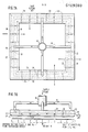
- FIG. 7A A third preferred embodiment of this invention is shown in Figures 7A and 7B.
- This configuration of a green sheet pick-up head utilizes the same aspirator jet suction techniques of the Figure 6 embodiment in the context of a larger pick-up head configuration.
- a supply from nozzle 10 is directed into a feed manifold which comprises four segments each feeding air into portions of the pick-up head having a plenum 22.
- the plenum 22 extends circumferentially about the device wherein each segment comprises a top member 20 and a bottom member 30.
- a series of radially directed slots 32 radiate from the plenum 22 in a manner corresponding to that of the embodiment of Figure 6 each pair of slots being coupled to the plenum 22 by a single feed orifice.
- a slot jet flow therefore emanates from the slots 32 in a manner corresponding to the prior embodiment.
- corner portions of member 30 are beveled at surfaces 24 to tailor the extent of the surface in contact with the green sheet. That is, the bottom surface 12 is selectively varied by the extent of the bevel 24 on both sides of the lower surface 12. Consequently, the amount of green sheet surface area which contacts surface 12 can be optimized as a function of that bevel.
- the corners of each slot may be radiused to improve flow characteristics.
- Fig. 7B shows an average suction force F which is due to the aspiration effect of air released by the slots 32. When that force equals and counteracts the weight of the green sheet, the sheet is attached to the head, that is, attached to surface 12.
- Figures 7A and 7B illustrates a symmetrical manifold arrangement from a common inlet source. Consequently, air issuing from the multiple slots 32 generates a suction which attracts in a uniform manner the approaching sheet to the surface 12. Given the sensitive nature of the green sheet material, the beveling construction, while not affecting the suction operation of the device, allows minimum yet effective contact to occur.
- the focused aspiration flow characteristics of a partially enclosed gas jet move parallel to the planar surface of a flexible sheet.
- This flow condition manifests itself as a continuously generated suction effect in the region bounded by the slot and sheet surfacels.
- the parallel gas stream induces a boundary layer frictional force on the sheet acting in the direction of the flow.
- the slots need not be directed radially outward, but as pick-up conditions dictate, be offset or skewed vis-a-vis the center of the pick-up head. Also, since the invention finds application for use with flexible materials, it is apparent that it can be employed to lift rigid wafers.
Abstract
Description
- This invention relates to a pick-up and transfer head for handling flexible and fragile materials, in particular by employing aspirated air flow to transfer flexible and fragile materials while maintaining them in a planar shape.
- In the manufacture of semiconductor devices, ceramic modules having multiple layers require transportation during various processing steps. These modules comprise multiple layers of ceramic materials with each sheet or layers of the ceramic having a particular conductive pattern imprinted thereon. Typically, the layers are aligned to provide a stack of uncured ceramics which is then pressed and cured to form an integral ceramic package having a very large number of electrically connected conductive paths arranged therein. However, prior to curing, each of the layers and the stack itself is flexible and highly fragile.
- In the prior art, a variety of techniques have been proposed and utilized to handle and stack these sheets known commonly as "green sheets". Techniques have evolved from hand-stacking to the use of suction devices. Give the fact that each individual green sheet is thin, and very flimsy, they are subject to stretching as well as local deformation if subjected to hand processing. To eliminate these problems, such as fingerprints, tearing and the like, a myriad of pick-up heads have been proposed to pick up and transfer green sheets between various processing steps without damaging the material. A standing requirement for all such devices is to define a device which is capable of supporting the green sheet on both its periphery and center to prevent stretching and tearing prior to subsequent process steps, such as imprinting, placement in a final stack and curing. Given the sensitivity of the material which is being handled, devices which are customarily used for the movement of cured (hard) wafers cannot be satisfactorily implemented for use in handling flimsy sheets.
- One such prior art technique is based on lifting wafers by utilizing the Bernoulli or axi-radial flow phenomenon. In this technique, both attraction and repelling forces are generated when an axially directed stream impinges on a flat surface (wafer) and then flows radially outward in a bounding flow passage configuration. If proper flow conditions are established, the attraction force dominates and the flat object is then lifted toward the transfer head. Such techniques are suitable for rigid planar materials but are not effective where flexible, fragile materials must be transported. The theory of "axi-radial" flow is discussed in U.S. Patent 4 257 637.
- Other devices to lift objects having a flat surface by means of this flow phenomenon are shown and described in U.S. Patents 3 539 216 and 3 411 770. In the 3 539 2161 patent, flow conditions are established in radially opposite directions across the surface of the body for lifting by Bernoulli effect. The flow may be directed in an unbalanced state over the surface to urge the wafer against a lateral restraint. In the U.S. Patent 3 411 770, a jet of air is directed vertically downward onto a stack of sheets. The velocity of the vertical stream in its radial excursion then creates a pressure differential acting to lift the top sheet of the stack when it is displaced at a predetermined position. Hence, a characteristic of both these prior art references is the use of both repelling and attraction forces which are generated when an axially directed gas stream impinges on a flat surface and then flows radially outward in a bounding flow passage. Under proper flow conditions, the attraction force tends to dominate and the object, if free to move, will then be lifted and drawn toward the opposite surface on the transfer head. Other examples of utilizing the Bernoulli effect for lifting and handling rigid planar materials with orientation by edge contact are shown in IBM Technical Disclosure Bulletin, Vol. 18, No. 6, pp. 1836-1837 (Nov. 1975) and IBM Technical Disclosure Bulletin, Vol. 20, No. 2, pp. 593-594 (July 1977).
- Also within the technology employing the Bernoulli theory are a group of pick-up heads which are used for lifting rigid planar wafers by edge contact. This technique is shown in U.S. Patent 3 523 706 and U.S. Patent 4 257 637. Reference is also made to IBM Technical Disclosure Bulletin Nos. Vol. 11, No. 2, p. 112 (July 1968); Vol. 17, No. 1, p. 84 (June 1974); Vol. 18, No. 8, p. 2447 (Jan. 1976); and Vol. 22, No. 5, pp. 1864-1865 (Oct. 1979).
- A technique distinguishable from Bernoulli effects in the prior art employs the application of a vacuum by which objects are lifted utilizing an array of suction ports on the transportation head which are in turn connected to a remote source of vacuum. The vacuum source may be either a vacuum pump or the throat section of a venturi tube. Typical are the techniques disclosed in U.S. Patent 3 648 853 and U.S. Patent 4 185 814. In the 3 648 853 patent, a plurality of pick-up vacuum cups are connected to the throat of a venturi tube to effectuate lifting of a flat work piece. In the 4 185 814 patent, green sheet material is utilized under vacuum control employing a manifold system so that upon the application of a vacuum, pick-up occurs and by reversing the pressure such that a positive pressure exists, discharge of the sheets can then be effectuated. In utilizing vacuum techniques, flow-balancing between the port is extremely sensitive. Moreover, line clogging tendencies are known problems in vacuum systems. The technique of lifting objects in an efficient manner is therefore difficult because of the sensitive nature of the pressures utilized in such vacuum approaches.
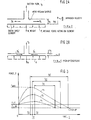
- The difficulties of vacuum systems when applied to the problem of pick-up and transportation of individual green sheets from an alternate sheet-spacer, layered stack will now be explained relative to Figures 1-3. As shown in Fig. lA, a pick-up head is positioned in a fixed vertical position and has an arrangement of ports and slots through which a suction force is exerted by means of an attached vacuum source. A stack comprising alternate layers of green sheet material and spacers is moved upward toward the pick-up head at a stack approach velocity v. That is, the stack approaches the head at a given velocity and is then stopped in a position where the top greer| sheet is disposed in close proximity to the vacuum surface of the head. In actuality, the top green sheet is essentially in contact with that head surface. Continuous pumping through the head surface openings reduces the intervening pressure to a level where an average attraction force is attained which is equal to the weight of the individual green sheet. Thus, when the stack is then retracted, the top green sheet remains behind attracted to and held by the pick-up head.
- There are, however, known deficiencies with this system. For example, the head may fail to pick up a sheet due to an insufficient attraction force. There is also a time-rate development of the attraction force which is a function of system parameters such as stack approach velocity, v, dwell time of the stack in proximity to the pick-up head, sheet flexibility, and the true surface spacing in the contact position. By true surface spacing, this parameter refers to the precision in stopping the stack at a predetermined head-stack spacing, h, as shown in Fig. lA, the texture of the green sheet material and the like. Moreover, a prime consideration is the pumping effectiveness at the head surface. This parameter is a function of the number, size, shape, and arrangement of the suction ports, vis-a-vis the "true" spacing in the dwell period.
- As shown in Fig. 1B, as the stack approaches the pick-up head, air is momentarily entrapped between the surfaces of the top green sheet and the vacuum surface of the pick-up head. There is a tendency to create a pressure increase above ambient conditions; however, this tendency is continuously counteracted by suction pumping and by the initial flow expulsion from the space between the surfaces. Expulsion flow q is shown in Fig. 1B alpng with the suction flow q . Within the dwell period, the pumping action must be sufficient to rapidly reduce the pressure to a level that will produce the required attraction force. If it is insufficient then the green sheet will not be retained by the pick-up head when the stack is retracted.
- By model analysis as shown in Fig. 2 and Fig. 3, for a given pumping effectiveness, it can be shown that the force on the sheet characteristically reaches a maximum followed by a steady decrease to a negative value where it is equal to the sheet weight. The extent of this behavior is a function of the approach velocity v and thus, for higher approach velocities (i.e., shorter travel time), a correspondingly larger minimum dwell time is required to achieve pick-up conditions. Fig. 2A provides a force diagram showing the condition where equilibrium is not attained such that the green sheet will not be held by the head, while, Fig. 2B shows the force conditions necessary to establish pick up. In FIG. 2A the expulsion flow qe is directed outward, while in a pick-up condition the force q', in FIG. 2B, is directed inwardly. During the transition period between the conditions shown in FIG. 2A and FIG. 2B the expulsion flow passes through zero.
- Fig. 3 plots force F as a function of time and, for a given pumping effectiveness, the plots demonstrate that the force on the sheet characteristically goes through a maximum force value followed by a steady decrease to a minimum value or is equal to the sheet weight. In Fig. 3, tf is the travel time and td, is the dwell time at the pick-up condition height hf. The curves establish the relationship v1 < v2 < v3. In Fig. 3, at t = 0:h = hO as shown in Fig. 2A. For t = tf:h = hf as shown in Fig. 2B.
- Given the operational variations inherent in such suction systems, the pick-up condition will not be attained in every cycling of the stack. One way to reduce the incidence of this occurrence is to decrease the approach velocity while increasing the dwell time. Such a technique reduces the maximum force while providing more than the minimum dwell time for the generation of the pick-up force. Fig. 3 shows increasing dwell time td at the pick-up position hf. Such a technique, however, is not completely sufficient to eliminate the problem in view of other variations inherent in pumping systems. For example, pumping effectiveness is especially important. In existing devices utilizing ports and slots, together with a vacuum pump, the suction process is essentially of the "sink" type. Hence, careful sheet-head positioning requirements are generally involved to most effectively utilize the suction field effect created by the ports on the lower side of the pick-up head. The field effect can be enhanced, for example, by the use of a larger number of small diameter ports which are spread to a larger extent over the vacuum head surface. Such an approach, however, involves increased practical problems, such as pressure drop-flow limitations between ports, and pumps, problems of port clogging and the like.
- Given these deficiencies in the prior art, the present invention is related to a different technique of achieving lifting by creating a suction field. The present invention, however, does not require a vacuum source but rather is based on the recognition that the aspiration properties of the gas jet provide the necessary force characteristics to uniformly and gently lift and holdiflat delicate objects, such as green sheets. By the use of a particular structure incorporating multiple gas jets, the aggregate aspiration effects are manifested as a suction effect at the lower surface of the pick-up device. Consequently, when a green sheet is placed in proximity to this surface, it will be attracted and held in place.
- It is therefore the object of the present invention to provide a device that will pick up delicate objects, such as green sheets and transport them for processing, whereby the pick-up head utilizes the aspiration effects of an air jet to attract a flat surface placed in proximity to the device surface.
- This object is attained in accordance with the invention as claimed in
claim 1. - In comparison with existing devices utilizing ports connected to a vacuum pump by using aspirator characteristics construction in accordance with the invention is inherently simplified yet positive performance advantages are attained. One principal advantage is that the aspirated air flow characteristics produce a larger integrated suction effect over a larger region of the head. Thus, a sheet is more effectively attracted to the surface of the device, an important criterion in the case of flexible easily damaged green sheets. Moreover, because pressurized jets are used to create suction, line clogging tendencies are minimized. In operation, the device is thoroughly insensitive to variations in flow conditions.
- A complete description of the invention will be set forth with reference to the following detailed description tak n with the accompanying drawings.
- FIG. 1A are schematic cross sections of known and FIG. 1B pick-up devices showing the relationship of the object being picked up with the device;
- FIG. 2A are schematic cross sections of a prior and FIG. 2B art pick-up device utilizing suction techniques;
- FIG. 3 is a diagram showing the relationship of a force as a function of time for operation of a suction device;
- FIG. 4 is a schematic view showing air flow lines of a free jet issuing into atmosphere including aspirated air flow;
- FIG. 5 is a perspective view of one embodiment illustrating the aspiration characteristics of a confined air jet in a slot wall system;
- FIGS. 6A, 6B, are bottom plan, side, and elevation 6C and 6D views, respectively, of a second embodiment of this invention; and
- FIG. 7A are plan and side elevation views
- and FIG. 7B respectively of a third embodiment of this invention.
- Referring now to Figure 4, streamlines of a free jet issuing into the atmosphere are shown. In Figure 4, a
supply orifice 10 produces an air jet having a flow path substantially perpendicular to awall portion 12. The air issuing from the jet may be either laminar or turbulent. Flow lines created by aspirated flow are generated as shown in Figure 4. That is, due to entrainment of the issuing air jet, streamlines are created which are directed inwardly and generally parallel to thewall surface 12 and then define streamlines generally parallel to the air jet. Flow rates tend to increase in the axial direction. A typical velocity profile (normal to the axial direction) is shown in Figure 4 for the air jets and the aspirated air flow. Hence, a free air jet issuing into the atmosphere characteristically entrains surrounding air. This flow condition can be used by confining the jet on three sides to focus the aspiration effect into a slot region. - Reference is made to Figure 5 illustrating one embodiment of this invention. An
orifice 10 receives a supply of air and discharges it into aslot 14. This embodiment shows a single slot system. The slot has three wall surfaces and an opening defining a suction slot. Due to aspirated air flow into the slot, a suction region occurs. The entraining or aspiration effect is therefore focused into the slot region which exists over a large portion of the slot. The magnitude and extent of the suction are a function of the slot geometry and supply flow conditions. As shown in Fig. 5, theslot 14 is elongate and straight. The elongate dimension relative to slot width is necessary to achieve steady state aspiration. A series of ports, each discrete over the same slot length would not achieve steady state conditions. - The slot edges 15 are shown to be sharp, orthogonal to the slot openings. Improved flow characteristics may be achieved by radiusing these edges to promote laminar flow around the corner. The slot need not be straight. In some applications a curved or sinuous slot may be employed.
- Utilizing these flow characteristics and the single slot system, Figs. 6A, 6B, 6C, and 6D illustrate a second embodiment of the present invention. This embodiment utilizes two components, a
plate 20 having the air supply flow andnozzle 10 and aplenum 22. Thesecond member 30 contains a series ofslots 32 positioned radially outward from the bottom surface and in fluid communication with theplenum 22 by means of a network offeed orifices 34. As shown in Fig. 6A, a bottom plan view, each pair ofslots 32 is coupled to theplenum 22 by asingle feed orifice 34. The plenum in turn is coupled to the supply flow by means of thenozzle 10.Members conventional coupling elements 36. Hence, in thebottom member 30, a series ofparallel slots 32 and orifice feedgrooves 34 are machined into that member. The number and placement of theslots 32 is a function of the ultimate utilization of the device vis-a-vis the material to be handled. Thetop member 20 contains the plenum and flow supply port with the two members attached as shown in Fig. 6B. - Gas under pressure is then supplied from
nozzle 10 into theplenum 22. It is fed via thefeed orifices 34 into the slots where, as shown in Fig. 6A, a slotted flow jet emanates. As shown in Figures 5B and 5C, theslot jets 32, as a result of aspiration, tend to generate a suction effect. Accordingly, a surface placed generally parallel to theend wall 12 will be attacted and held at that surface. - It has been found that a long narrow groove passage defining the slots is much more effective than a short plate orifice. In operation, the device of Figures 6A-6D can be operated over a wide range of flow supply pressures. It is capable of effectively picking up and holding flexible as well as rigid materials. For example, at a supply pressure of approximately 0,28 bar, materials such as tissue paper, cloth or wafers are easily attracted and held by the transfer head. At the same time, flow consumption requirements are modest because of the small feed groove dimensions. Inherently, the pumping action of the slots produces a more extensive suction action due to the flow behavior in the slot regions. Hence, wider variations in sheet-head positioning can be tolerated without adverse effects on performance. Stated differently, accurate registration between the green sheet supply and the pick-up head is more readily tolerated in the device in accordance with the embodiment shown in Figures 6A-6D.
- A third preferred embodiment of this invention is shown in Figures 7A and 7B. This configuration of a green sheet pick-up head utilizes the same aspirator jet suction techniques of the Figure 6 embodiment in the context of a larger pick-up head configuration. As shown in Fig. 7A, a supply from
nozzle 10 is directed into a feed manifold which comprises four segments each feeding air into portions of the pick-up head having aplenum 22. Theplenum 22 extends circumferentially about the device wherein each segment comprises atop member 20 and abottom member 30. A series of radially directedslots 32 radiate from theplenum 22 in a manner corresponding to that of the embodiment of Figure 6 each pair of slots being coupled to theplenum 22 by a single feed orifice. A slot jet flow therefore emanates from theslots 32 in a manner corresponding to the prior embodiment. As shown in Fig. 7B, corner portions ofmember 30 are beveled atsurfaces 24 to tailor the extent of the surface in contact with the green sheet. That is, thebottom surface 12 is selectively varied by the extent of thebevel 24 on both sides of thelower surface 12. Consequently, the amount of green sheet surface area which contacts surface 12 can be optimized as a function of that bevel. Also, as mentioned in connection with the FIG. 5 embodiment, the corners of each slot may be radiused to improve flow characteristics. - Fig. 7B shows an average suction force F which is due to the aspiration effect of air released by the
slots 32. When that force equals and counteracts the weight of the green sheet, the sheet is attached to the head, that is, attached to surface 12. - The embodiment of Figures 7A and 7B illustrates a symmetrical manifold arrangement from a common inlet source. Consequently, air issuing from the
multiple slots 32 generates a suction which attracts in a uniform manner the approaching sheet to thesurface 12. Given the sensitive nature of the green sheet material, the beveling construction, while not affecting the suction operation of the device, allows minimum yet effective contact to occur. - In this invention, the focused aspiration flow characteristics of a partially enclosed gas jet move parallel to the planar surface of a flexible sheet. This flow condition manifests itself as a continuously generated suction effect in the region bounded by the slot and sheet surfacels. At the same time, the parallel gas stream induces a boundary layer frictional force on the sheet acting in the direction of the flow. By providing the array of slots as shown in the preferred embodiments, the aggregate effect of these forces is to lift and hold the sheet on the head. Accordingly, following these principles a number of different slot arrangements may be defined. While not illustrated the slot or slots may be curved or sinuous. The slots need not be directed radially outward, but as pick-up conditions dictate, be offset or skewed vis-a-vis the center of the pick-up head. Also, since the invention finds application for use with flexible materials, it is apparent that it can be employed to lift rigid wafers.
Claims (8)
Applications Claiming Priority (2)
| Application Number | Priority Date | Filing Date | Title |
|---|---|---|---|
| US442206 | 1982-11-16 | ||
| US06/442,206 US4474397A (en) | 1982-11-16 | 1982-11-16 | Pick-up head utilizing aspirated air flow |
Publications (2)
| Publication Number | Publication Date |
|---|---|
| EP0109080A1 true EP0109080A1 (en) | 1984-05-23 |
| EP0109080B1 EP0109080B1 (en) | 1987-07-22 |
Family
ID=23755925
Family Applications (1)
| Application Number | Title | Priority Date | Filing Date |
|---|---|---|---|
| EP83111346A Expired EP0109080B1 (en) | 1982-11-16 | 1983-11-14 | Pick-up head for moving a sheet of material |
Country Status (4)
| Country | Link |
|---|---|
| US (1) | US4474397A (en) |
| EP (1) | EP0109080B1 (en) |
| JP (1) | JPS5992545A (en) |
| DE (1) | DE3372681D1 (en) |
Cited By (6)
| Publication number | Priority date | Publication date | Assignee | Title |
|---|---|---|---|---|
| DE3536432A1 (en) * | 1985-10-12 | 1987-04-16 | Telefunken Electronic Gmbh | Contactless holding device for semiconductor discs |
| DE3920035A1 (en) * | 1988-07-04 | 1990-01-11 | Kuttler Hans Juergen | Apparatus for the isolation and transportation of workpieces |
| AT1527U1 (en) * | 1995-07-12 | 1997-06-25 | Sez Semiconduct Equip Zubehoer | SUPPORT FOR DISC-SHAPED OBJECTS, IN PARTICULAR SILICO DISC |
| WO1999046199A1 (en) * | 1998-03-13 | 1999-09-16 | Ab Initio | Vacuum ejector with a number of suction cups |
| US6022417A (en) * | 1995-07-12 | 2000-02-08 | Sumnitsch; Franz | Support for wafer-shaped objects, in particular silicon wafers |
| DE102009047086A1 (en) * | 2009-11-24 | 2011-05-26 | J. Schmalz Gmbh | Compressed air-operated low pressure gripper has housing, particularly rectangular-shaped housing with compressed air inlet and flow chamber that is opened towards suction side |
Families Citing this family (14)
| Publication number | Priority date | Publication date | Assignee | Title |
|---|---|---|---|---|
| US5067762A (en) * | 1985-06-18 | 1991-11-26 | Hiroshi Akashi | Non-contact conveying device |
| DE3822597A1 (en) * | 1988-07-04 | 1990-01-11 | Siemens Ag | Adjusting device and method for adjusting a robot arm for use in automated production areas, in particular in semiconductor technology |
| US5470420A (en) * | 1992-07-31 | 1995-11-28 | Eastman Kodak Company | Apparatus for label application using Bernoulli Effect |
| US6455186B1 (en) | 1998-03-05 | 2002-09-24 | Black & Decker Inc. | Battery cooling system |
| US6095582A (en) * | 1998-03-11 | 2000-08-01 | Trusi Technologies, Llc | Article holders and holding methods |
| GB9822153D0 (en) * | 1998-10-09 | 1998-12-02 | Labflax Systems Ltd | Apparatus for applying labels to moving articles |
| JP4391655B2 (en) | 2000-02-22 | 2009-12-24 | インターナショナル・ビジネス・マシーンズ・コーポレーション | Air tweezers |
| US7007942B1 (en) | 2003-03-25 | 2006-03-07 | Wps Industries, Inc. | Panel handling apparatus |
| JP3703464B2 (en) * | 2003-04-04 | 2005-10-05 | キヤノン株式会社 | manipulator |
| WO2010108462A1 (en) * | 2009-03-26 | 2010-09-30 | Jonas & Redmann Automationstechnik Gmbh | Bernoulli gripper apparatus having at least one bernoulli gripper |
| US9490156B2 (en) * | 2013-05-23 | 2016-11-08 | Asm Technology Singapore Pte Ltd | Transfer device for holding an object using a gas flow |
| WO2016132448A1 (en) * | 2015-02-17 | 2016-08-25 | 富士機械製造株式会社 | Suction attachment nozzle |
| JP6651327B2 (en) * | 2015-10-15 | 2020-02-19 | 東レエンジニアリング株式会社 | Air float device for sheet material |
| JP2018122381A (en) * | 2017-01-31 | 2018-08-09 | ブラザー工業株式会社 | Component holding device |
Citations (8)
| Publication number | Priority date | Publication date | Assignee | Title |
|---|---|---|---|---|
| US3411770A (en) * | 1966-08-04 | 1968-11-19 | Sperry Rand Corp | Sheet separator |
| US3523706A (en) * | 1967-10-27 | 1970-08-11 | Ibm | Apparatus for supporting articles without structural contact and for positioning the supported articles |
| US3539216A (en) * | 1968-01-11 | 1970-11-10 | Sprague Electric Co | Pickup device |
| US3648853A (en) * | 1970-04-03 | 1972-03-14 | Erie Eng Co | Vacuum work pick-up attachment for work device |
| US4029351A (en) * | 1976-06-02 | 1977-06-14 | International Business Machines Corporation | Bernoulli pickup head with self-restoring anti-tilt improvement |
| DE2524916B2 (en) * | 1975-06-05 | 1978-03-16 | Reifenhaeuser Kg, 5210 Troisdorf | Gripping device for solid bodies |
| US4185814A (en) * | 1977-12-12 | 1980-01-29 | International Business Machines Corporation | Pick up and placement head for green sheet and spacer |
| US4257637A (en) * | 1979-09-28 | 1981-03-24 | International Business Machines Corporation | Contactless air film lifting device |
Family Cites Families (5)
| Publication number | Priority date | Publication date | Assignee | Title |
|---|---|---|---|---|
| JPS5113308B2 (en) * | 1972-07-03 | 1976-04-27 | ||
| JPS5420963Y2 (en) * | 1974-07-16 | 1979-07-27 | ||
| GB1513444A (en) * | 1974-09-06 | 1978-06-07 | Chemical Reactor Equip As | Pick-up devices for lifting and moving semiconductor wafers |
| JPS56156580U (en) * | 1980-04-18 | 1981-11-21 | ||
| JPS58141536A (en) * | 1982-02-17 | 1983-08-22 | Sanyo Electric Co Ltd | Attracting head of semiconductor wafer |
-
1982
- 1982-11-16 US US06/442,206 patent/US4474397A/en not_active Expired - Lifetime
-
1983
- 1983-10-11 JP JP58188583A patent/JPS5992545A/en active Granted
- 1983-11-14 EP EP83111346A patent/EP0109080B1/en not_active Expired
- 1983-11-14 DE DE8383111346T patent/DE3372681D1/en not_active Expired
Patent Citations (8)
| Publication number | Priority date | Publication date | Assignee | Title |
|---|---|---|---|---|
| US3411770A (en) * | 1966-08-04 | 1968-11-19 | Sperry Rand Corp | Sheet separator |
| US3523706A (en) * | 1967-10-27 | 1970-08-11 | Ibm | Apparatus for supporting articles without structural contact and for positioning the supported articles |
| US3539216A (en) * | 1968-01-11 | 1970-11-10 | Sprague Electric Co | Pickup device |
| US3648853A (en) * | 1970-04-03 | 1972-03-14 | Erie Eng Co | Vacuum work pick-up attachment for work device |
| DE2524916B2 (en) * | 1975-06-05 | 1978-03-16 | Reifenhaeuser Kg, 5210 Troisdorf | Gripping device for solid bodies |
| US4029351A (en) * | 1976-06-02 | 1977-06-14 | International Business Machines Corporation | Bernoulli pickup head with self-restoring anti-tilt improvement |
| US4185814A (en) * | 1977-12-12 | 1980-01-29 | International Business Machines Corporation | Pick up and placement head for green sheet and spacer |
| US4257637A (en) * | 1979-09-28 | 1981-03-24 | International Business Machines Corporation | Contactless air film lifting device |
Non-Patent Citations (6)
| Title |
|---|
| IBM TECHNICAL DISCLOSURE BULLETIN, vol. 11, no. 2, July 1968 *C.P. HAYUNGA "WAFER PICKUP WITH AIR BARRIER" PAGE 112* * |
| IBM TECHNICAL DISCLOSURE BULLETIN, vol. 17, no. 1, June 1974 *R.H. BRUNNER "WAFER CHUCK" PAGE 84 * * |
| IBM TECHNICAL DISCLOSURE BULLETIN, vol. 18, no. 6, November 1975 *H. VON BURG ET AL: "ORIENTING BERNOULLI EFFECT WAFER TRANSFER MECHANISM" PAGES 1836, 1837 * * |
| IBM TECHNICAL DISCLOSURE BULLETIN, vol. 18, no. 8, January 1976 *R.F. BOUDAH; A:C: KEY "WAFER SENSING BERNOULLI HEAD "PAGE 2447 * * |
| IBM TECHNICAL DISCLOSURE BULLETIN, vol. 20, no. 2, July 1977 *B.C. O'NEILL ET AL. "ANNULAR ORIENTOR" PAGES 593, 594 * * |
| IBM TECHNICAL DISCLOSURE BULLETIN, vol. 22, no. 5, October 1979 3W:B:BALDER; R,P, CACHON "DIVERTED FLOW BERNOULLI PICK UP DEVICE " PAGES 1864,1865 * * |
Cited By (7)
| Publication number | Priority date | Publication date | Assignee | Title |
|---|---|---|---|---|
| DE3536432A1 (en) * | 1985-10-12 | 1987-04-16 | Telefunken Electronic Gmbh | Contactless holding device for semiconductor discs |
| DE3920035A1 (en) * | 1988-07-04 | 1990-01-11 | Kuttler Hans Juergen | Apparatus for the isolation and transportation of workpieces |
| AT1527U1 (en) * | 1995-07-12 | 1997-06-25 | Sez Semiconduct Equip Zubehoer | SUPPORT FOR DISC-SHAPED OBJECTS, IN PARTICULAR SILICO DISC |
| US6022417A (en) * | 1995-07-12 | 2000-02-08 | Sumnitsch; Franz | Support for wafer-shaped objects, in particular silicon wafers |
| WO1999046199A1 (en) * | 1998-03-13 | 1999-09-16 | Ab Initio | Vacuum ejector with a number of suction cups |
| US6467825B1 (en) | 1998-03-13 | 2002-10-22 | Pronomic Ab | Vacuum ejector with a number of suction cups |
| DE102009047086A1 (en) * | 2009-11-24 | 2011-05-26 | J. Schmalz Gmbh | Compressed air-operated low pressure gripper has housing, particularly rectangular-shaped housing with compressed air inlet and flow chamber that is opened towards suction side |
Also Published As
| Publication number | Publication date |
|---|---|
| EP0109080B1 (en) | 1987-07-22 |
| DE3372681D1 (en) | 1987-08-27 |
| JPS5992545A (en) | 1984-05-28 |
| JPH0353777B2 (en) | 1991-08-16 |
| US4474397A (en) | 1984-10-02 |
Similar Documents
| Publication | Publication Date | Title |
|---|---|---|
| EP0109080B1 (en) | Pick-up head for moving a sheet of material | |
| US5067762A (en) | Non-contact conveying device | |
| KR100675408B1 (en) | Carrying unit | |
| US5169196A (en) | Non-contact pick-up head | |
| JP5219173B2 (en) | Non-contact type vacuum pad | |
| US20130108409A1 (en) | Thin substrate, mass-transfer bernoulli end-effector | |
| US4172513A (en) | Article handling apparatus using air flow to provide article orientation | |
| US3796455A (en) | Air flow actuated overhead pickup device for limp sheet materials | |
| US6647791B1 (en) | Device for contactlessly gripping and positioning components | |
| JP3445138B2 (en) | Non-contact transfer device | |
| JP2002127070A (en) | Plate-like body holder | |
| KR101187684B1 (en) | Non-contact air pads for chucking a substrate by using the radial flow | |
| JP5384305B2 (en) | Work transfer device | |
| JP6716136B2 (en) | Fluid flow former and non-contact transfer device | |
| KR101261313B1 (en) | Apparatus for aligning and pick up transporting of moving object | |
| JPH0151413B2 (en) | ||
| JP2001105369A (en) | Carrying device | |
| JPH05335404A (en) | Non-contact retaining equipment | |
| US6981312B2 (en) | System for handling microelectronic dies having a non-piercing die ejector | |
| JP2697013B2 (en) | Clamping device | |
| JPH0328029Y2 (en) | ||
| JP3050910B2 (en) | Device for holding thin plate members | |
| JP3054896B2 (en) | Air holding device for plate with small holes | |
| JPH0533534U (en) | Sample holder | |
| JPH02138044A (en) | Holding device for platelike body |
Legal Events
| Date | Code | Title | Description |
|---|---|---|---|
| PUAI | Public reference made under article 153(3) epc to a published international application that has entered the european phase |
Free format text: ORIGINAL CODE: 0009012 |
|
| AK | Designated contracting states |
Designated state(s): DE FR GB |
|
| 17P | Request for examination filed |
Effective date: 19840921 |
|
| GRAA | (expected) grant |
Free format text: ORIGINAL CODE: 0009210 |
|
| AK | Designated contracting states |
Kind code of ref document: B1 Designated state(s): DE FR GB |
|
| REF | Corresponds to: |
Ref document number: 3372681 Country of ref document: DE Date of ref document: 19870827 |
|
| ET | Fr: translation filed | ||
| PLBE | No opposition filed within time limit |
Free format text: ORIGINAL CODE: 0009261 |
|
| STAA | Information on the status of an ep patent application or granted ep patent |
Free format text: STATUS: NO OPPOSITION FILED WITHIN TIME LIMIT |
|
| 26N | No opposition filed | ||
| PGFP | Annual fee paid to national office [announced via postgrant information from national office to epo] |
Ref country code: GB Payment date: 19931019 Year of fee payment: 11 |
|
| PGFP | Annual fee paid to national office [announced via postgrant information from national office to epo] |
Ref country code: FR Payment date: 19931103 Year of fee payment: 11 |
|
| PGFP | Annual fee paid to national office [announced via postgrant information from national office to epo] |
Ref country code: DE Payment date: 19931118 Year of fee payment: 11 |
|
| PG25 | Lapsed in a contracting state [announced via postgrant information from national office to epo] |
Ref country code: GB Effective date: 19941114 |
|
| GBPC | Gb: european patent ceased through non-payment of renewal fee |
Effective date: 19941114 |
|
| PG25 | Lapsed in a contracting state [announced via postgrant information from national office to epo] |
Ref country code: FR Effective date: 19950731 |
|
| PG25 | Lapsed in a contracting state [announced via postgrant information from national office to epo] |
Ref country code: DE Effective date: 19950801 |
|
| REG | Reference to a national code |
Ref country code: FR Ref legal event code: ST |