EP0125060A2 - Detecting luminescent security features - Google Patents
Detecting luminescent security features Download PDFInfo
- Publication number
- EP0125060A2 EP0125060A2 EP84302699A EP84302699A EP0125060A2 EP 0125060 A2 EP0125060 A2 EP 0125060A2 EP 84302699 A EP84302699 A EP 84302699A EP 84302699 A EP84302699 A EP 84302699A EP 0125060 A2 EP0125060 A2 EP 0125060A2
- Authority
- EP
- European Patent Office
- Prior art keywords
- document
- luminescence
- security
- detecting
- sensing means
- Prior art date
- Legal status (The legal status is an assumption and is not a legal conclusion. Google has not performed a legal analysis and makes no representation as to the accuracy of the status listed.)
- Withdrawn
Links
- 238000004020 luminiscence type Methods 0.000 claims abstract description 45
- 238000000034 method Methods 0.000 claims description 23
- 239000002131 composite material Substances 0.000 claims description 3
- 239000000835 fiber Substances 0.000 abstract description 5
- 230000005855 radiation Effects 0.000 description 2
- KKQWHYGECTYFIA-UHFFFAOYSA-N 2,5-dichlorobiphenyl Chemical compound ClC1=CC=C(Cl)C(C=2C=CC=CC=2)=C1 KKQWHYGECTYFIA-UHFFFAOYSA-N 0.000 description 1
- 238000003491 array Methods 0.000 description 1
- 238000001914 filtration Methods 0.000 description 1
- 229910052736 halogen Inorganic materials 0.000 description 1
- 238000005286 illumination Methods 0.000 description 1
- 230000000977 initiatory effect Effects 0.000 description 1
- 239000000463 material Substances 0.000 description 1
- 238000001228 spectrum Methods 0.000 description 1
- 229910052721 tungsten Inorganic materials 0.000 description 1
- 239000010937 tungsten Substances 0.000 description 1
- -1 tungsten halogen Chemical class 0.000 description 1
- 238000011144 upstream manufacturing Methods 0.000 description 1
Images


Classifications
-
- G—PHYSICS
- G07—CHECKING-DEVICES
- G07F—COIN-FREED OR LIKE APPARATUS
- G07F7/00—Mechanisms actuated by objects other than coins to free or to actuate vending, hiring, coin or paper currency dispensing or refunding apparatus
- G07F7/08—Mechanisms actuated by objects other than coins to free or to actuate vending, hiring, coin or paper currency dispensing or refunding apparatus by coded identity card or credit card or other personal identification means
- G07F7/086—Mechanisms actuated by objects other than coins to free or to actuate vending, hiring, coin or paper currency dispensing or refunding apparatus by coded identity card or credit card or other personal identification means by passive credit-cards adapted therefor, e.g. constructive particularities to avoid counterfeiting, e.g. by inclusion of a physical or chemical security-layer
-
- G—PHYSICS
- G07—CHECKING-DEVICES
- G07D—HANDLING OF COINS OR VALUABLE PAPERS, e.g. TESTING, SORTING BY DENOMINATIONS, COUNTING, DISPENSING, CHANGING OR DEPOSITING
- G07D7/00—Testing specially adapted to determine the identity or genuineness of valuable papers or for segregating those which are unacceptable, e.g. banknotes that are alien to a currency
- G07D7/06—Testing specially adapted to determine the identity or genuineness of valuable papers or for segregating those which are unacceptable, e.g. banknotes that are alien to a currency using wave or particle radiation
- G07D7/12—Visible light, infrared or ultraviolet radiation
- G07D7/121—Apparatus characterised by sensor details
-
- G—PHYSICS
- G07—CHECKING-DEVICES
- G07D—HANDLING OF COINS OR VALUABLE PAPERS, e.g. TESTING, SORTING BY DENOMINATIONS, COUNTING, DISPENSING, CHANGING OR DEPOSITING
- G07D7/00—Testing specially adapted to determine the identity or genuineness of valuable papers or for segregating those which are unacceptable, e.g. banknotes that are alien to a currency
- G07D7/20—Testing patterns thereon
Definitions
- the invention relates to a method and apparatus for detecting luminescent security features in or on documents.
- a method of detecting luminescent security features in or on documents comprises illuminating a test document with an interrogation beam; sensing luminescence emitted from the document with sensing means; dividing the area over which luminescence is sensed into a plurality of portions; comparing the intensity of the luminescence of each portion with the average intensity of all the portions; and detecting the presence of a security feature if the two intensities satisfy a predetermined realtionship.
- a detector for detecting luminescent security features in or on documents comprising means for illuminating a test document with an interrogation beam; sensing means for sensing luminescence emitted from the document; and discriminating means for discriminating between luminescence due to a security feature and other luminescence emitted by the document, the discriminating means comprising means for comparing the average intensity of the luminescence emitted over a plurality of adjacent portions of the document with the intensity of each portion and detecting means for detecting whether the compared intensities satisfy a predetermined relationship.
- the relationship between the two intensities may be for example a minimum ratio which must be achieved or possibly the two intensities could be subtracted one from the other and the presence of the security feature detected if the difference exceeds a predetermined threshold.
- the method may further comprise repeating the sensing step over a plurality of areas of the document, and detecting the presence of a composite security feature if a predetermined arrangement of individual security features are detected.
- a method is particularly suitable for detecting a luminescent security thread, the method comprising feeding a test document past the sensing means in a direction such that a security thread will extend in the feed direction; sensing luminescence emitted from a plurality of sets of adjacent portions of the test document, each set of adjacent portions being aligned transversely to the security thread; determining which portion or portions of each set of portions has emitted luminescence corresponding to a security feature; and detecting the presence of a security thread if security features are detected for each set of portions in positions which are arranged in a manner corresponding to a security thread.
- Such an arrangement could be a straight line.
- the document containing the security thread passes the sensing means with the thread extending parallel to the direction of motion.
- the method further comprises periodically checking for failure of the sensing means and this may be carried out between successive documents. This enables the method to be substantially automated since the checking step will reveal any failure in the sensing means and such failure can be indicated by means of a suitable alarm.
- the checking step may be carried out by checking means which preferably comprises means for ensuring that no luminescence is sensed when no document is being illuminated; and means for illuminating the sensing means and means to check that the sensing means then senses the apparent presence of luminescence.
- the checking means includes circuitry for ensuring that the output from the sensing means does not exceed a low level threshold when no document is present.
- the means for illuminating the sensing means may be a light emitting diode (LED).
- the apparatus preferably further comprises another sensing means positioned on the opposite side of the document to the one sensing means to detect luminescence emitted from that side of the document.
- the or each sensing means comprises a photo-diode array. This is particularly suitable for dividing the area over which luminescence is sensed into a plurality of portions.
- the or each sensing means comprises a line of sensors, the line being transverse, in use, to the security thread.
- the detector according to the second aspect of the invention may be used in apparatus for automatically detecting the presence of security features on a plurality of documents.
- means are provided for automatically feeding successive ones of the documents past the illuminating means and the sensing means; together with means for indicating a document in which a security feature has not been detected.
- the detector is capable of detecting security features very rapidly and this enables high speed operation to be underaken (e.g. 20 bank notes/sec).
- the detector includes checking means as outlined above and further comprises means for indicating the presence of a fault in the or each sensing means. This is particularly useful for fully automated operation since the indicating means can for example generate a fault signal for terminating operation and/or initiating an alarm.
- the checking means is operable between successive documents so that after each document is processed a check is carried out.
- the form of the interrogation beam depends on the nature of the luminescent security feature but is typically white light causing the luminescent security feature to luminesce in the infra-red. With a suitable choice of filters and light source, security features luminescing in other regions of the spectrum may be detected, when illuminating with other than visible light. Furthermore, by arranging to sense luminescence a predetermined time interval after the document has been illuminated by the interrogation beam, or by suitably modulating the interrogation beam and including de-modulating circuitry in the processing circuitry, it is possible to differentiate between fluorescence and phosphorescence.
- a bank note 1 having a rectangular shape is illustrated in Figure 1A.
- a luminescent security thread 2 extends across the width of the bank note 1. In this case, the security thread 2 is incorporated within the paper of the bank note.
- a detector for detecting the security thread 2 is illustrated in Figure 1B.
- the detector may be incorporated in automatic bank note sorting apparatus (not shown).
- the detector comprises a housing 3 of circular cross-section one end 4 of which is closed while a filter 5 is mounted, at the other end.
- the filter 5 transmits, in this case, infra-red luminescence but will be chosen in general to match the characteristics of the security features to be detected in order to filter out unwanted wavelengths.
- a lens 6 is mounted in the housing 3 adjacent the filter 5 and is arranged to focus luminescence passing through the filter 5 onto a photo-diode array 7.
- the photo-diode array 7 is mounted on a support 8 secured within the housing 3.
- the photo-diode array 7 is electrically connected to circuitry on a printed circuit board 9 also mounted (by means not shown) in the housing 3.
- the circuitry is illustrated in Figure 2.
- a light emitting diode (LED) 10 is mounted in an outwardly extending support 11 fixed in an aperture 12 in the housing 3.
- the LED 10 is arranged to direct light onto the photo-diode array 7 when it is illuminated.
- the detector also includes a tungsten halogen light source 13 mounted to another housing part (not shown) which is arranged to transmit visible, white light through an infra-red absorbing filter 14 into a fibre optic light guide 15.
- the fibre optic light guide 15 is mounted to the housing 3 by a suitable clamp 16.
- the fibre optic light guide 15 terminates in a fishtail portion 17 which directs light onto an area 18.
- documents 1 are fed in succession by a conventional means such as conveyor belts (not shown) under the housing 3 and the light guide 15 in the direction of the arrow 19.
- the documents 1 are fed so that the security thread 2 is parallel with the direction of motion.
- the photo-diode array 7 comprises a single line of photo-diodes arranged transversely to the direction of movement of the document.
- Light from the light source 13 is first filtered to remove infra-red wavelengths by the filter 14 and is then directed via the fibre optic fishtail 17 onto the document 1.
- a strip of the illuminated surface of the document 1 is then imaged onto the photo-diode array 7 by the lens 6 and the infra-red transmitting filter 5 removes all visible wavelengths from the light beam and thus prevents any reflected light from reaching the array 7.
- the photo-diode array 7 unless a luminsecent feature on or in the document is stimulated by the incident visible light to emit infra-red radiation.
- a small amount of light of the unwanted wavelengths may be transmitted by the filters 5, 14, so that a small signal may be generated by the elements of the array 7 but this can be dealt with by the circuitry to be described.
- the width of document to be interrogated is chosen as appropriate depending on the expected position of the security thread 2.
- the document 1 is scanned as it passes beneath the lower end of the housing 3 and a typical interval between scans is 1 mm. This may be adjusted to suit specific documents.
- the image of the security thread 2, when focused onto the photo-diode array 7, will cause one (or an adjacent pair) of the photo-diode outputs to be significantly different from all the others. It is this property which is looked for when the signals are processed.
- the signal processing circuitry is illustrated in Figure 2.
- the outputs of the diode array 7 are sequentially multiplexed by a multiplexer 20 into a single analogue datastream.
- the outputs from the photo-diode array 7 are also fed to a circuit 21 for obtaining the means output and from there to a variable resistance 22 which feeds a preset fraction of the mean output to a comparator 23.
- the single analogue datastream output from the multiplexer 20 is also fed to the comparator 23 so that a comparison is made between each photo-diode output and the mean of the entire array. The result of this comparison, now a digital signal, is auto-correlated.
- Auto-correlation is achieved by taking the digital signal from the comparator 23 and feeding this to a delay circuit 24 and to an AND gate 25.
- the output of the delay circuit 24 is then fed to the AND gate 25 where it is ANDed with the undelayed signal to produce the desired auto-correlation.
- the auto-correlated signal from the AND gate 25 is then counted by a counter 26 and if the counter output exceeds a preset value, the security thread 2 is deemed to be detected and a latch 27 is set.
- the counter 26 will be set to count a sufficient number of scans for all or a large portion of the security thread to be scanned.
- Control electronics 28 of conventional form (such as a microprocessor) is also provided on the PCB 9 to carry out two checks on the diodes of the photo-diode array 7. Firstly, the control electronics looks momentarily at the outputs of the photo-diodes in the array 7 between the passage of successive documents 1 (when light from the source 13-will not be reflected through the filter 5) to ensure that the output signal of each diode is below a low level threshold setting. Secondly, the LED 10 is momentarily activated between the passage of successive documents and the control electronics 28 checks the outputs of each diode of the photo-diode array 7 to ensure that each has an output that exceeds a high level threshold. If a fault is detected during the tests the control electronics 28 provides a suitable output signal.
- the control electronics 28 looks momentarily at the outputs of the photo-diodes in the array 7 between the passage of successive documents 1 (when light from the source 13-will not be reflected through the filter 5) to ensure that the output signal of each diode
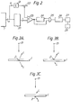
- Figure 3A illustrates a document 1 having a security thread 2 incorporated within the document.
- a document 1 passes beneath the detector illustrated in Figure 1B, strong luminescence (L) is emitted on both sides of the document 1, as indicated by the long arrows in Figure 3A.
- Figure 3B illustrates the case where a security thread 2 is provided on the surface which is illuminated and in this case strong luminescence occurs from that surface but only a weak luminescence (L) indicated by the relatively short arrow will be detected from the other surface.
- Figure 3C illustrates the same document 1 of Figure 3B but after having been reversed when only weak luminscence (L) will occur from both sides of the document 1.
- Figure 4 illustrates diagramatically another example of a detector in this case for discriminating between a document 1 having an internal security thread 2 as shown in Figure 3A and a document having a security thread 2 on its surface.
- the apparatus of Figure 4 is essentially the same as that shown in Figure 1B but with the addition of a second housing 3' having exactly the same components as the housing 3 but positioned on the opposite side of the document 1 to the housing 3. Additional illumination means are not, however, provided.
- the photo-diode array (not shown) supported by the housing 3' will detect luminenscence emitted from the adjacent side of the document 1 and by comparing the intensities of luminescence detected by each photo-diode array using suitable electronic circuitry (not shown) the authenticity of the security thread 2 can be determined. In other words, a document will only be classified as genuine if luminescence of sufficient strength is sensed by both photo-diode arrays.
- the output from the latch 27 is fed to the control electronics 28 which provides an ouput indicating the presence or absence of a security feature in or on the document.
- the apparatus of Figure 1B may be used but with the modified circuitry shown in Figure 5.
- the interrogation beam supplied by the source 13 is modulated at a frequency F and the output from the photo-diode array 7 is fed to a phase sensitive detector 29 to which is also supplied the frequency F.
- the output from the phase sensitive detector 29 is fed via a low pass filter 30 to the multiplexer 20 and the circuit 21 shown in Figure 2. Since the interrogation beam supplied by the source 13 is not continuous it is possible to distinguish between fluorescent and phosphorescent features using the circuitry shown in Figure 5.
- the area 18 which is illuminated may be positioned upstream from the position shown in Figure 1B so that luminescence is received by the diode array 7 a predetermined time interval after the test document has been illuminated with the interrogation beam so that fluorescent and phosephorescent features may be differentiated.
Abstract
Luminsecent security features in or on documents are detected using a detector comprising a fibre optic light guide (15) arranged to transmit an interrogation beam originating from a source (13) onto a document to be tested; and a housing (3) in which a photo-diode array (7) is mounted to receive luminescence emitted from the document. The photo-diode array (7) is connected to electronic circuitry (not shown) for discriminating between luminescence due to a security feature and other luminescence emitted by the document and for determining that a security feature has been detected.
Description
- The invention relates to a method and apparatus for detecting luminescent security features in or on documents.
- It has been proposed in the past to irradiate security documents, particularly paper sheets such as bank notes, with ultra-violet radiation to determine whether or not the document is luminescent. The generation of a bluish luminescence can be indicative of a forged document. Recently, luminescent materials have been incorporated into, or printed on, documents to provide security features in themselves. One form of security feature is a luminescent thread. Previous methods for detecting such security features involve using accurate and complex filtering techniques to detect whether luminescence emitted by the document falls within a particular wavelength band. These methods do not enable security features which luminesce at substantially the same wavelength as other features to be discriminated.
- In accordance with one aspect of the present invention, a method of detecting luminescent security features in or on documents comprises illuminating a test document with an interrogation beam; sensing luminescence emitted from the document with sensing means; dividing the area over which luminescence is sensed into a plurality of portions; comparing the intensity of the luminescence of each portion with the average intensity of all the portions; and detecting the presence of a security feature if the two intensities satisfy a predetermined realtionship.
- We also provide in accordance with a second aspect of the present invention a detector for detecting luminescent security features in or on documents, the detector comprising means for illuminating a test document with an interrogation beam; sensing means for sensing luminescence emitted from the document; and discriminating means for discriminating between luminescence due to a security feature and other luminescence emitted by the document, the discriminating means comprising means for comparing the average intensity of the luminescence emitted over a plurality of adjacent portions of the document with the intensity of each portion and detecting means for detecting whether the compared intensities satisfy a predetermined relationship.
- With this method and apparatus, we are able to detect luminescent security features even where the luminescence of the security feature has substantially the same wavelength as other parts of the documents.
- The relationship between the two intensities may be for example a minimum ratio which must be achieved or possibly the two intensities could be subtracted one from the other and the presence of the security feature detected if the difference exceeds a predetermined threshold.
- In one example, the method may further comprise repeating the sensing step over a plurality of areas of the document, and detecting the presence of a composite security feature if a predetermined arrangement of individual security features are detected. Such a method is particularly suitable for detecting a luminescent security thread, the method comprising feeding a test document past the sensing means in a direction such that a security thread will extend in the feed direction; sensing luminescence emitted from a plurality of sets of adjacent portions of the test document, each set of adjacent portions being aligned transversely to the security thread; determining which portion or portions of each set of portions has emitted luminescence corresponding to a security feature; and detecting the presence of a security thread if security features are detected for each set of portions in positions which are arranged in a manner corresponding to a security thread. Such an arrangement could be a straight line.
- Preferably, the document containing the security thread passes the sensing means with the thread extending parallel to the direction of motion.
- If a minimum number of individual security features, representing successive portions of the security thread, are detected then a composite security feature comprising the whole thread is detected.
- Conveniently, the method further comprises periodically checking for failure of the sensing means and this may be carried out between successive documents. This enables the method to be substantially automated since the checking step will reveal any failure in the sensing means and such failure can be indicated by means of a suitable alarm.
- The checking step may be carried out by checking means which preferably comprises means for ensuring that no luminescence is sensed when no document is being illuminated; and means for illuminating the sensing means and means to check that the sensing means then senses the apparent presence of luminescence.
- In one example, the checking means includes circuitry for ensuring that the output from the sensing means does not exceed a low level threshold when no document is present. The means for illuminating the sensing means may be a light emitting diode (LED).
- It is possible that a forger might try to duplicate a luminescent security feature normally incorporated into the document by providing a similar feature on a surface of the document. In order to detect such a forgery, the apparatus preferably further comprises another sensing means positioned on the opposite side of the document to the one sensing means to detect luminescence emitted from that side of the document.
- With this arrangement, if the forged feature is on the side of the document which is illuminated it will strongly luminesce on that side while relatively weak luminescence will be detected on the other side of the document. In contrast, a genuine security feature within the document will strongly luminesce on both sides of the document.
- Preferably, the or each sensing means comprises a photo-diode array. This is particularly suitable for dividing the area over which luminescence is sensed into a plurality of portions. Conveniently, where the detector is arranged to detect a security thread, the or each sensing means comprises a line of sensors, the line being transverse, in use, to the security thread.
- One important advantage of the detector according to the second aspect of the invention is that it may be used in apparatus for automatically detecting the presence of security features on a plurality of documents. In this case, means are provided for automatically feeding successive ones of the documents past the illuminating means and the sensing means; together with means for indicating a document in which a security feature has not been detected.
- The detector is capable of detecting security features very rapidly and this enables high speed operation to be underaken (e.g. 20 bank notes/sec).
- In one convenient form, the detector includes checking means as outlined above and further comprises means for indicating the presence of a fault in the or each sensing means. This is particularly useful for fully automated operation since the indicating means can for example generate a fault signal for terminating operation and/or initiating an alarm. Conveniently, the checking means is operable between successive documents so that after each document is processed a check is carried out.
- The form of the interrogation beam depends on the nature of the luminescent security feature but is typically white light causing the luminescent security feature to luminesce in the infra-red. With a suitable choice of filters and light source, security features luminescing in other regions of the spectrum may be detected, when illuminating with other than visible light. Furthermore, by arranging to sense luminescence a predetermined time interval after the document has been illuminated by the interrogation beam, or by suitably modulating the interrogation beam and including de-modulating circuitry in the processing circuitry, it is possible to differentiate between fluorescence and phosphorescence.
- Two examples of methods and detectors in accordance with the present invention will now be described with reference to the accompanying drawings, in which:-
- Figure lA is a plan of a document incorporating a security thread;
- Figure 1B is a diagrammatic view of a detector;
- Figure 2 illustrates circuitry for use with the detector of Figure 1B;
- Figures 3A, 3B, 3C are diagrammatic cross-sections through bank notes illustrating how forged and genuine security features are distinguished;
- Figure 4 is a diagrammatic illustration of apparatus for use in detecting the forged documents shown in Figures 3B and 3C; and,
- Figure 5 illustrates additional circuitry for use when detecting phosphorescent security features.
- A bank note 1 having a rectangular shape is illustrated in Figure 1A. A
luminescent security thread 2 extends across the width of the bank note 1. In this case, thesecurity thread 2 is incorporated within the paper of the bank note. - A detector for detecting the
security thread 2 is illustrated in Figure 1B. The detector may be incorporated in automatic bank note sorting apparatus (not shown). The detector comprises ahousing 3 of circular cross-section one end 4 of which is closed while a filter 5 is mounted, at the other end. The filter 5 transmits, in this case, infra-red luminescence but will be chosen in general to match the characteristics of the security features to be detected in order to filter out unwanted wavelengths. A lens 6 is mounted in thehousing 3 adjacent the filter 5 and is arranged to focus luminescence passing through the filter 5 onto a photo-diode array 7. The photo-diode array 7 is mounted on a support 8 secured within thehousing 3. The photo-diode array 7 is electrically connected to circuitry on a printed circuit board 9 also mounted (by means not shown) in thehousing 3. The circuitry is illustrated in Figure 2. - A light emitting diode (LED) 10 is mounted in an outwardly extending support 11 fixed in an
aperture 12 in thehousing 3. The LED 10 is arranged to direct light onto the photo-diode array 7 when it is illuminated. The detector also includes a tungstenhalogen light source 13 mounted to another housing part (not shown) which is arranged to transmit visible, white light through an infra-red absorbingfilter 14 into a fibreoptic light guide 15. The fibreoptic light guide 15 is mounted to thehousing 3 by a suitable clamp 16. The fibreoptic light guide 15 terminates in afishtail portion 17 which directs light onto anarea 18. - In use, documents 1 are fed in succession by a conventional means such as conveyor belts (not shown) under the
housing 3 and thelight guide 15 in the direction of thearrow 19. The documents 1 are fed so that thesecurity thread 2 is parallel with the direction of motion. The photo-diode array 7 comprises a single line of photo-diodes arranged transversely to the direction of movement of the document. Light from thelight source 13 is first filtered to remove infra-red wavelengths by thefilter 14 and is then directed via the fibreoptic fishtail 17 onto the document 1. A strip of the illuminated surface of the document 1 is then imaged onto the photo-diode array 7 by the lens 6 and the infra-red transmitting filter 5 removes all visible wavelengths from the light beam and thus prevents any reflected light from reaching the array 7. Thus, no light reaches the photo-diode array 7 unless a luminsecent feature on or in the document is stimulated by the incident visible light to emit infra-red radiation. In practice, a small amount of light of the unwanted wavelengths may be transmitted by thefilters 5, 14, so that a small signal may be generated by the elements of the array 7 but this can be dealt with by the circuitry to be described. - The width of document to be interrogated is chosen as appropriate depending on the expected position of the
security thread 2. The document 1 is scanned as it passes beneath the lower end of thehousing 3 and a typical interval between scans is 1 mm. This may be adjusted to suit specific documents. - The image of the
security thread 2, when focused onto the photo-diode array 7, will cause one (or an adjacent pair) of the photo-diode outputs to be significantly different from all the others. It is this property which is looked for when the signals are processed. - The signal processing circuitry is illustrated in Figure 2. In order to reduce the complexity of the processing electronics, the outputs of the diode array 7 are sequentially multiplexed by a
multiplexer 20 into a single analogue datastream. The outputs from the photo-diode array 7 are also fed to acircuit 21 for obtaining the means output and from there to a variable resistance 22 which feeds a preset fraction of the mean output to acomparator 23. The single analogue datastream output from themultiplexer 20 is also fed to thecomparator 23 so that a comparison is made between each photo-diode output and the mean of the entire array. The result of this comparison, now a digital signal, is auto-correlated. Auto-correlation is achieved by taking the digital signal from thecomparator 23 and feeding this to adelay circuit 24 and to an ANDgate 25. The output of thedelay circuit 24 is then fed to the ANDgate 25 where it is ANDed with the undelayed signal to produce the desired auto-correlation. The auto-correlated signal from the ANDgate 25 is then counted by acounter 26 and if the counter output exceeds a preset value, thesecurity thread 2 is deemed to be detected and alatch 27 is set. - If a scan is carried out at 1 mm intervals as indicated previously, the
counter 26 will be set to count a sufficient number of scans for all or a large portion of the security thread to be scanned. -
Control electronics 28 of conventional form (such as a microprocessor) is also provided on the PCB 9 to carry out two checks on the diodes of the photo-diode array 7. Firstly, the control electronics looks momentarily at the outputs of the photo-diodes in the array 7 between the passage of successive documents 1 (when light from the source 13-will not be reflected through the filter 5) to ensure that the output signal of each diode is below a low level threshold setting. Secondly, the LED 10 is momentarily activated between the passage of successive documents and thecontrol electronics 28 checks the outputs of each diode of the photo-diode array 7 to ensure that each has an output that exceeds a high level threshold. If a fault is detected during the tests thecontrol electronics 28 provides a suitable output signal. - Figure 3A illustrates a document 1 having a
security thread 2 incorporated within the document. When such a document 1 passes beneath the detector illustrated in Figure 1B, strong luminescence (L) is emitted on both sides of the document 1, as indicated by the long arrows in Figure 3A. If, however, a document having a luminescent security thread or luminescent ink on its surface passes beneath the detector of Figure 1B, the intensity of luminescence (L) emitted on each side of the document will differ. Figure 3B illustrates the case where asecurity thread 2 is provided on the surface which is illuminated and in this case strong luminescence occurs from that surface but only a weak luminescence (L) indicated by the relatively short arrow will be detected from the other surface. Conversely, Figure 3C illustrates the same document 1 of Figure 3B but after having been reversed when only weak luminscence (L) will occur from both sides of the document 1. - Figure 4 illustrates diagramatically another example of a detector in this case for discriminating between a document 1 having an
internal security thread 2 as shown in Figure 3A and a document having asecurity thread 2 on its surface. The apparatus of Figure 4 is essentially the same as that shown in Figure 1B but with the addition of a second housing 3' having exactly the same components as thehousing 3 but positioned on the opposite side of the document 1 to thehousing 3. Additional illumination means are not, however, provided. The photo-diode array (not shown) supported by the housing 3' will detect luminenscence emitted from the adjacent side of the document 1 and by comparing the intensities of luminescence detected by each photo-diode array using suitable electronic circuitry (not shown) the authenticity of thesecurity thread 2 can be determined. In other words, a document will only be classified as genuine if luminescence of sufficient strength is sensed by both photo-diode arrays. - The output from the
latch 27 is fed to thecontrol electronics 28 which provides an ouput indicating the presence or absence of a security feature in or on the document. - Where it is desired to discriminate between phosphoresecent and fluorescent features, the apparatus of Figure 1B may be used but with the modified circuitry shown in Figure 5. In this case, the interrogation beam supplied by the
source 13 is modulated at a frequency F and the output from the photo-diode array 7 is fed to a phasesensitive detector 29 to which is also supplied the frequency F. The output from the phasesensitive detector 29 is fed via alow pass filter 30 to themultiplexer 20 and thecircuit 21 shown in Figure 2. Since the interrogation beam supplied by thesource 13 is not continuous it is possible to distinguish between fluorescent and phosphorescent features using the circuitry shown in Figure 5. - In an alternative arrangement (not shown) the
area 18 which is illuminated may be positioned upstream from the position shown in Figure 1B so that luminescence is received by the diode array 7 a predetermined time interval after the test document has been illuminated with the interrogation beam so that fluorescent and phosephorescent features may be differentiated.
Claims (18)
1. A method of detecting luminescent security features in or on documents (1), the method comprising illuminating a test document with an interrogation beam; sensing luminescence emitted from the document with sensing means (7); dividing the area over which luminescence is sensed into a plurality of portions; comparing the intensity of the luminescence of each portion with the average intensity of all the portions; and detecting the presence of a security feature (2) if the two intensities satisfy a predetermined relationship.
2. A method according to claim 1, further comprising repeating the sensing step over a plurality of areas of the document, and detecting the presence of a composite security feature (2) if a predetermined arrangement of individual security features are detected.
3. A method according to claim 2 for detecting a luminescent security thread (2), the method comprising feeding a test document (1) past the sensing means (7) in a direction such that a security thread will extend in the feed direction (19); sensing luminescence emitted from a plurality of sets of adjacent portions of the test document, each set of adjacent portions being aligned transversely to the security thread; determining which portion or portions of each set of portions has emitted luminescence corresponding to a security feature; and detecting the presence of a security thread (2) if security features are detected for each set of portions in positions which are arranged in a manner corresponding to a security thread.
4. A method according to any of claims 1 to 3, further comprising periodically checking for failure of the sensing means (7).
5. A method according to claim 4, wherein the checking step is carried out between successive documents.
6. A method according to any of the preceding claims, wherein luminescence (L) emitted from both sides of the document (1) is sensed.
7. A method according to any of the preceding claims, wherein the interrogation beam is modulated, and the sensed luminescence is first demodulated prior to the comparing step so that fluorescent and phosphorescent features may be differentiated.
8. A method according to any of claims 1 to 6, wherein the sensing means senses luminescence emitted from the document a predetermined time interval after the test document has been illuminated with the interrogation beam so that fluorescent and phosphorescent features may be differentiated.
9. A method according to any of the preceding claims, wherein the predetermined relationship comprises a minimum predetermined threshold which must be exceeded by the difference between the two intensities.
10. A detector for detecting luminescent security features in or on documents (1), the detector comprising means (13,15) for illuminating a test document (1) with an interrogation beam; sensing means (7) for sensing luminescence emitted from the document (1); and discriminating means (20-27) for discriminating between luminescence due to a security feature and other luminescence emitted by the document, the discriminating means comprising comparison means (23) for comparing the average intensity of the luminescence emitted over a plurality of adjacent portions of the document with the intensity of each portion and detecting means (26) for detecting whether the compared intensities satisfy a predetermined relationship.
11. A detector according to claim 10, further comprising checking means (28,10) for checking for failure of the sensing means.
12. A detector according to claim 11, wherein the checking means comprises means (28) for ensuring that no luminescence is sensed when no document is being illuminated; and means (10) for illuminating the sensing means (7) and means (28) to check that the sensing means then senses the apparent presence of luminescence.
13. A detector according to any of claims 10 to 12, further comprising another sensing means positioned on the opposite side of the document (1) to the one sensing means (7) to detect luminescence emitted from that side of the document (1).
14. A detector according to any of claims 10 to 13, wherein the or each sensing means comprises a photo-diode array (7).
15. A detector according to any of claims 10 to 14, for detecting a luminescent security thread (2), wherein the or each sensing means comprises a line of sensors (7), the line being transverse, in use, to the security thread.
16. Apparatus for automatically detecting the presence of security features in a plurality of documents, the apparatus comprising a detector according to any of claims 10 to 15, means for automatically feeding successive ones of the documents past -the illuminating means (13,15) and the sensing means (7); and means (28) for indicating a document in which a security feature has not been detected.
17. Apparatus according to claim 16, when dependant on claim 10 or claim 11, further comprising means (28) for indicating the presence of a fault in the or each.sensing means.
18. Apparatus according to claim 17, wherein the checking means (28, 10) is operable between successive documents.
Applications Claiming Priority (2)
| Application Number | Priority Date | Filing Date | Title |
|---|---|---|---|
| GB8311795 | 1983-04-29 | ||
| GB838311795A GB8311795D0 (en) | 1983-04-29 | 1983-04-29 | Detecting luminescent security features |
Publications (2)
| Publication Number | Publication Date |
|---|---|
| EP0125060A2 true EP0125060A2 (en) | 1984-11-14 |
| EP0125060A3 EP0125060A3 (en) | 1986-10-08 |
Family
ID=10541935
Family Applications (1)
| Application Number | Title | Priority Date | Filing Date |
|---|---|---|---|
| EP84302699A Withdrawn EP0125060A3 (en) | 1983-04-29 | 1984-04-19 | Detecting luminescent security features |
Country Status (4)
| Country | Link |
|---|---|
| US (1) | US4650320A (en) |
| EP (1) | EP0125060A3 (en) |
| ES (1) | ES532028A0 (en) |
| GB (1) | GB8311795D0 (en) |
Cited By (11)
| Publication number | Priority date | Publication date | Assignee | Title |
|---|---|---|---|---|
| FR2600191A1 (en) * | 1986-06-17 | 1987-12-18 | Laurel Bank Machine Co | PAPER COINS DISCRIMINATOR |
| EP0314312A2 (en) * | 1987-10-26 | 1989-05-03 | De La Rue Systems Limited | Method and apparatus for detecting inks |
| DE3815375A1 (en) * | 1988-04-18 | 1989-10-26 | Landis & Gyr Ag | DEVICE FOR DETECTING THE AUTHENTICITY OF DOCUMENTS |
| WO1991008556A1 (en) * | 1989-11-24 | 1991-06-13 | Price Stern Sloan, Inc. | Security print detectors |
| GB2240947A (en) * | 1990-02-20 | 1991-08-21 | Aco Electronics Limited | Authentification of documents with luminescent security features |
| WO1998026276A1 (en) * | 1996-12-09 | 1998-06-18 | Giesecke & Devrient Gmbh | Device and method for detecting fluorescent and phosphorescent light |
| AT403967B (en) * | 1992-11-18 | 1998-07-27 | Oesterr Nationalbank | DOCUMENT AND FILM STRUCTURE FOR PRODUCING A DOCUMENT |
| GB2334574A (en) * | 1998-02-19 | 1999-08-25 | Panoptic Limited | Apparatus for the detection of counterfeit items by their fluorescence |
| EP2278558A3 (en) * | 2004-07-22 | 2012-01-25 | Giesecke & Devrient GmbH | Apparatus and method for examining value documents |
| WO2014072707A1 (en) * | 2012-11-06 | 2014-05-15 | Essentra Packaging & Security Limited | An authentication device |
| CN106204892A (en) * | 2016-08-18 | 2016-12-07 | 浙江然鹏电子有限公司 | A kind of multispectral transmitting and reception device |
Families Citing this family (29)
| Publication number | Priority date | Publication date | Assignee | Title |
|---|---|---|---|---|
| US5790693A (en) * | 1990-02-05 | 1998-08-04 | Cummins-Allison Corp. | Currency discriminator and authenticator |
| US5960103A (en) * | 1990-02-05 | 1999-09-28 | Cummins-Allison Corp. | Method and apparatus for authenticating and discriminating currency |
| US5652802A (en) * | 1990-02-05 | 1997-07-29 | Cummins-Allison Corp. | Method and apparatus for document identification |
| US5295196A (en) * | 1990-02-05 | 1994-03-15 | Cummins-Allison Corp. | Method and apparatus for currency discrimination and counting |
| US5151595A (en) * | 1990-10-16 | 1992-09-29 | Simon Marketing, Inc. | Imaging device and method for developing, duplicating and printing graphic media |
| US5306642A (en) * | 1992-12-21 | 1994-04-26 | The United States Of America As Represented By The Department Of Energy | Device for aqueous detection of nitro-aromatic compounds |
| US6915893B2 (en) * | 2001-04-18 | 2005-07-12 | Cummins-Alliston Corp. | Method and apparatus for discriminating and counting documents |
| US6220419B1 (en) | 1994-03-08 | 2001-04-24 | Cummins-Allison | Method and apparatus for discriminating and counting documents |
| JP3345239B2 (en) * | 1995-01-11 | 2002-11-18 | ローレルバンクマシン株式会社 | Bill validator |
| GB2309778B (en) | 1996-02-05 | 2000-05-24 | Mars Inc | Security document validation |
| GB9717194D0 (en) * | 1997-08-13 | 1997-10-22 | De La Rue Thomas & Co Ltd | Detector methods and apparatus |
| US6201662B1 (en) | 1998-09-25 | 2001-03-13 | Iomega Corporation | Latent illuminance discrimination marker with reflective layer for data storage cartridges |
| US6359745B1 (en) | 1997-09-26 | 2002-03-19 | Iomega Corporation | Latent illuminance discrimination marker system for data storage cartridges |
| US6091563A (en) * | 1997-09-26 | 2000-07-18 | Iomega Corporation | Latent illuminance discrimination marker system for data storage cartridges |
| US6264107B1 (en) | 1997-09-26 | 2001-07-24 | Iomega Corporation | Latent illuminance discrimination marker system for authenticating articles |
| US6181662B1 (en) | 1997-09-26 | 2001-01-30 | Iomega Corporation | Latent irradiance discrimination method and marker system for cartridgeless data storage disks |
| US6297924B1 (en) | 1998-11-13 | 2001-10-02 | Iomega Corporation | System and method for cartridge detection and verification using signal comparison |
| CN1209314C (en) * | 1999-02-17 | 2005-07-06 | 欧洲工业技术开发公司 | Method for producing an anhydrite III or based hydraulic bonding agent and obtained hydraulic bonding agent |
| AU772395B2 (en) * | 1999-02-17 | 2004-04-29 | Crane Canada Co. | Optical sensor with planar wall |
| US6731785B1 (en) | 1999-07-26 | 2004-05-04 | Cummins-Allison Corp. | Currency handling system employing an infrared authenticating system |
| DE10259293A1 (en) * | 2002-12-18 | 2004-07-22 | Giesecke & Devrient Gmbh | Banknote validity testing device with which luminescent light generated from security markings is detected, whereby light source and detector are arranged opposite to each other and banknotes are passed between them |
| EP1445099A1 (en) * | 2003-02-10 | 2004-08-11 | Kba-Giori S.A. | Sensor |
| JP2005100197A (en) * | 2003-09-26 | 2005-04-14 | Aruze Corp | Identification sensor and device |
| US8401268B1 (en) | 2007-03-09 | 2013-03-19 | Cummins-Allison Corp. | Optical imaging sensor for a document processing device |
| US8331643B2 (en) * | 2007-07-17 | 2012-12-11 | Cummins-Allison Corp. | Currency bill sensor arrangement |
| JP5959001B2 (en) * | 2012-07-20 | 2016-08-02 | 株式会社小森コーポレーション | Sheet inspection equipment |
| US9956464B2 (en) * | 2013-01-24 | 2018-05-01 | Wilson Sporting Goods Co. | Ball bat barrel with luminescent interior |
| RU179757U1 (en) * | 2017-10-09 | 2018-05-23 | Акционерное общество "Инженерный Промышленный Концерн "СТРАЖ" | SEAL AUTHENTICITY CONTROL DEVICE |
| DE102019005656A1 (en) * | 2019-08-12 | 2021-02-18 | Giesecke+Devrient Currency Technology Gmbh | Method and device for checking documents of value |
Citations (5)
| Publication number | Priority date | Publication date | Assignee | Title |
|---|---|---|---|---|
| FR2033680A5 (en) * | 1969-03-08 | 1970-12-04 | Satam | |
| FR2101714A5 (en) * | 1970-07-30 | 1972-03-31 | Nat Rejectors Gmbh | |
| FR2156331A1 (en) * | 1971-10-15 | 1973-05-25 | Martelli Mario | |
| US3820068A (en) * | 1972-06-29 | 1974-06-25 | Westinghouse Learning Corp | Background reference level system and method for document scanners |
| FR2443107A1 (en) * | 1978-12-01 | 1980-06-27 | Radioelectrique Comp Ind | METHOD FOR MONITORING THE PHYSICAL STATE OF A PRINTED DOCUMENT AND INSTALLATION FOR IMPLEMENTING THE METHOD |
Family Cites Families (13)
| Publication number | Priority date | Publication date | Assignee | Title |
|---|---|---|---|---|
| US4146792A (en) * | 1973-04-30 | 1979-03-27 | G.A.O. Gesellschaft Fur Automation Und Organisation Mbh | Paper secured against forgery and device for checking the authenticity of such papers |
| JPS5610643B2 (en) * | 1973-12-17 | 1981-03-10 | ||
| AT349791B (en) * | 1975-10-17 | 1979-04-25 | Gao Ges Automation Org | PROCEDURE FOR IDENTIFICATION OF FLUORESCENT SUBSTANCES AND SPECTRAL ABSORBENT FILTER FOR CARRYING OUT THE PROCEDURE |
| US4097731A (en) * | 1977-06-02 | 1978-06-27 | Burroughs Corporation | Automatic gain control for photosensing devices |
| CH622369A5 (en) * | 1978-04-18 | 1981-03-31 | Radioelectrique Comp Ind | |
| US4319137A (en) * | 1978-05-23 | 1982-03-09 | Tokyo Shibaura Denki Kabushiki Kaisha | Apparatus for identifying sheet-like printed matters |
| US4219277A (en) * | 1978-08-09 | 1980-08-26 | Westinghouse Electric Corp. | Method of detecting flaws on surfaces |
| GB2047402B (en) * | 1979-03-06 | 1983-03-09 | De La Rue Thomas & Co Ltd | Watermark detection |
| ES8203280A1 (en) * | 1980-05-30 | 1982-04-01 | Gao Ges Automation Org | Paper security with authenticity mark of luminescent material and method for the authentication thereof. |
| ES8204668A1 (en) * | 1980-05-30 | 1982-05-16 | Gao Ges Automation Org | Paper securities with authenticity mark of luminescent material. |
| CH659145A5 (en) * | 1980-05-30 | 1986-12-31 | Gao Ges Automation Org | METHOD FOR CHECKING THE VALIDITY OF SECURITIES SECURED WITH LUMINESCENT SUBSTANCES AND DEVICE FOR IMPLEMENTING THE METHOD. |
| US4529881A (en) * | 1982-03-02 | 1985-07-16 | Pyrotector, Inc. | Flame detector with test lamp and adjustable field of view |
| JPS58175091A (en) * | 1982-04-06 | 1983-10-14 | 株式会社東芝 | Security thread detector |
-
1983
- 1983-04-29 GB GB838311795A patent/GB8311795D0/en active Pending
-
1984
- 1984-04-19 EP EP84302699A patent/EP0125060A3/en not_active Withdrawn
- 1984-04-27 ES ES532028A patent/ES532028A0/en active Granted
- 1984-04-27 US US06/604,962 patent/US4650320A/en not_active Expired - Fee Related
Patent Citations (5)
| Publication number | Priority date | Publication date | Assignee | Title |
|---|---|---|---|---|
| FR2033680A5 (en) * | 1969-03-08 | 1970-12-04 | Satam | |
| FR2101714A5 (en) * | 1970-07-30 | 1972-03-31 | Nat Rejectors Gmbh | |
| FR2156331A1 (en) * | 1971-10-15 | 1973-05-25 | Martelli Mario | |
| US3820068A (en) * | 1972-06-29 | 1974-06-25 | Westinghouse Learning Corp | Background reference level system and method for document scanners |
| FR2443107A1 (en) * | 1978-12-01 | 1980-06-27 | Radioelectrique Comp Ind | METHOD FOR MONITORING THE PHYSICAL STATE OF A PRINTED DOCUMENT AND INSTALLATION FOR IMPLEMENTING THE METHOD |
Cited By (20)
| Publication number | Priority date | Publication date | Assignee | Title |
|---|---|---|---|---|
| FR2600191A1 (en) * | 1986-06-17 | 1987-12-18 | Laurel Bank Machine Co | PAPER COINS DISCRIMINATOR |
| EP0314312A2 (en) * | 1987-10-26 | 1989-05-03 | De La Rue Systems Limited | Method and apparatus for detecting inks |
| EP0314312A3 (en) * | 1987-10-26 | 1990-02-07 | De La Rue Systems Limited | Method and apparatus for detecting inks |
| US4935628A (en) * | 1987-10-26 | 1990-06-19 | De La Rue Systems Ltd. | Method and apparatus for detecting inks |
| DE3815375C5 (en) * | 1988-04-18 | 2004-07-15 | Mars, Inc. | Device for recognizing a document |
| DE3815375A1 (en) * | 1988-04-18 | 1989-10-26 | Landis & Gyr Ag | DEVICE FOR DETECTING THE AUTHENTICITY OF DOCUMENTS |
| US4922109A (en) * | 1988-04-18 | 1990-05-01 | Lgz Landis & Gyr Zug Ag | Device for recognizing authentic documents using optical modulas |
| WO1991008556A1 (en) * | 1989-11-24 | 1991-06-13 | Price Stern Sloan, Inc. | Security print detectors |
| GB2240947A (en) * | 1990-02-20 | 1991-08-21 | Aco Electronics Limited | Authentification of documents with luminescent security features |
| AT403967B (en) * | 1992-11-18 | 1998-07-27 | Oesterr Nationalbank | DOCUMENT AND FILM STRUCTURE FOR PRODUCING A DOCUMENT |
| US6165592A (en) * | 1992-11-18 | 2000-12-26 | Oesterreichische Nationalbank | Document with doped optical security attribute, layer composite for making same and test device for testing the document for authenticity |
| WO1998026276A1 (en) * | 1996-12-09 | 1998-06-18 | Giesecke & Devrient Gmbh | Device and method for detecting fluorescent and phosphorescent light |
| GB2334574A (en) * | 1998-02-19 | 1999-08-25 | Panoptic Limited | Apparatus for the detection of counterfeit items by their fluorescence |
| GB2334574B (en) * | 1998-02-19 | 2002-08-07 | Panoptic Ltd | Improvements in/or relating to the detection of counterfeit items |
| EP2278558A3 (en) * | 2004-07-22 | 2012-01-25 | Giesecke & Devrient GmbH | Apparatus and method for examining value documents |
| WO2014072707A1 (en) * | 2012-11-06 | 2014-05-15 | Essentra Packaging & Security Limited | An authentication device |
| CN104919498A (en) * | 2012-11-06 | 2015-09-16 | 益升华包装及安全有限公司 | An authentication device |
| JP2016500181A (en) * | 2012-11-06 | 2016-01-07 | エッセントラ パッケージング アンド セキュリティー リミテッド | Authentication device |
| US9536368B2 (en) | 2012-11-06 | 2017-01-03 | Essentra Packaging & Security Limited | Authentication device |
| CN106204892A (en) * | 2016-08-18 | 2016-12-07 | 浙江然鹏电子有限公司 | A kind of multispectral transmitting and reception device |
Also Published As
| Publication number | Publication date |
|---|---|
| US4650320A (en) | 1987-03-17 |
| EP0125060A3 (en) | 1986-10-08 |
| ES8600540A1 (en) | 1985-10-01 |
| ES532028A0 (en) | 1985-10-01 |
| GB8311795D0 (en) | 1983-06-02 |
Similar Documents
| Publication | Publication Date | Title |
|---|---|---|
| US4650320A (en) | Detecting luminescent security features | |
| EP0314312B1 (en) | Method and apparatus for detecting inks | |
| US5640463A (en) | Method and apparatus for authenticating documents including currency | |
| US5034616A (en) | Device for optically scanning sheet-like documents | |
| EP0668576B1 (en) | Bill discriminating apparatus for bill handling machine | |
| US5206699A (en) | Sensing a narrow frequency band of radiation and gemstones | |
| US7092583B2 (en) | Apparatus and method for detecting the authenticity of secured documents | |
| CA1334895C (en) | Sensing a narrow frequency band of radiation and gemstones | |
| US8263948B2 (en) | Authentication apparatus for moving value documents | |
| KR101037430B1 (en) | Inspection device | |
| AU777385B2 (en) | Antifalsification paper provided with applied coding consisting of luminescent mottled fibers | |
| EP1066602B1 (en) | Methods and apparatus for monitoring articles | |
| KR20120003980A (en) | Device and method for verifying value documents | |
| CZ295133B6 (en) | Method for checking authenticity of documents | |
| KR20070007333A (en) | Improved fake currency detector using integrated transmission and reflective spectral response | |
| US6024202A (en) | Detector methods and apparatus | |
| RU2301453C2 (en) | Method and device for checking authenticity of sheet material | |
| CN100562898C (en) | The apparatus and method of verifying valuable documents | |
| JP2001052232A (en) | Paper sheet genuine/false discrimination device | |
| CN112334957B (en) | Method and sensor for testing documents | |
| US20050121619A1 (en) | Document identification system | |
| JP3542223B2 (en) | Coin identification device | |
| JPH0954850A (en) | Paper money discrimination device | |
| JPS63148391A (en) | Paper money discriminator |
Legal Events
| Date | Code | Title | Description |
|---|---|---|---|
| PUAI | Public reference made under article 153(3) epc to a published international application that has entered the european phase |
Free format text: ORIGINAL CODE: 0009012 |
|
| AK | Designated contracting states |
Designated state(s): DE GB |
|
| PUAL | Search report despatched |
Free format text: ORIGINAL CODE: 0009013 |
|
| AK | Designated contracting states |
Kind code of ref document: A3 Designated state(s): DE GB |
|
| STAA | Information on the status of an ep patent application or granted ep patent |
Free format text: STATUS: THE APPLICATION IS DEEMED TO BE WITHDRAWN |
|
| 18D | Application deemed to be withdrawn |
Effective date: 19870409 |
|
| RIN1 | Information on inventor provided before grant (corrected) |
Inventor name: CHAPMAN, VICTOR BRIAN Inventor name: POTTER, MICHAEL |