EP0135340A1 - Method and apparatus for producing stereoscopic images - Google Patents
Method and apparatus for producing stereoscopic images Download PDFInfo
- Publication number
- EP0135340A1 EP0135340A1 EP84305380A EP84305380A EP0135340A1 EP 0135340 A1 EP0135340 A1 EP 0135340A1 EP 84305380 A EP84305380 A EP 84305380A EP 84305380 A EP84305380 A EP 84305380A EP 0135340 A1 EP0135340 A1 EP 0135340A1
- Authority
- EP
- European Patent Office
- Prior art keywords
- perspective
- light
- image
- spectral
- periods
- Prior art date
- Legal status (The legal status is an assumption and is not a legal conclusion. Google has not performed a legal analysis and makes no representation as to the accuracy of the status listed.)
- Granted
Links
Images


Classifications
-
- H—ELECTRICITY
- H04—ELECTRIC COMMUNICATION TECHNIQUE
- H04N—PICTORIAL COMMUNICATION, e.g. TELEVISION
- H04N13/00—Stereoscopic video systems; Multi-view video systems; Details thereof
- H04N13/30—Image reproducers
- H04N13/332—Displays for viewing with the aid of special glasses or head-mounted displays [HMD]
- H04N13/337—Displays for viewing with the aid of special glasses or head-mounted displays [HMD] using polarisation multiplexing
-
- G—PHYSICS
- G02—OPTICS
- G02B—OPTICAL ELEMENTS, SYSTEMS OR APPARATUS
- G02B30/00—Optical systems or apparatus for producing three-dimensional [3D] effects, e.g. stereoscopic images
- G02B30/20—Optical systems or apparatus for producing three-dimensional [3D] effects, e.g. stereoscopic images by providing first and second parallax images to an observer's left and right eyes
- G02B30/22—Optical systems or apparatus for producing three-dimensional [3D] effects, e.g. stereoscopic images by providing first and second parallax images to an observer's left and right eyes of the stereoscopic type
- G02B30/23—Optical systems or apparatus for producing three-dimensional [3D] effects, e.g. stereoscopic images by providing first and second parallax images to an observer's left and right eyes of the stereoscopic type using wavelength separation, e.g. using anaglyph techniques
-
- H—ELECTRICITY
- H04—ELECTRIC COMMUNICATION TECHNIQUE
- H04N—PICTORIAL COMMUNICATION, e.g. TELEVISION
- H04N13/00—Stereoscopic video systems; Multi-view video systems; Details thereof
- H04N13/10—Processing, recording or transmission of stereoscopic or multi-view image signals
- H04N13/106—Processing image signals
- H04N13/15—Processing image signals for colour aspects of image signals
-
- H—ELECTRICITY
- H04—ELECTRIC COMMUNICATION TECHNIQUE
- H04N—PICTORIAL COMMUNICATION, e.g. TELEVISION
- H04N13/00—Stereoscopic video systems; Multi-view video systems; Details thereof
- H04N13/10—Processing, recording or transmission of stereoscopic or multi-view image signals
- H04N13/106—Processing image signals
- H04N13/167—Synchronising or controlling image signals
-
- H—ELECTRICITY
- H04—ELECTRIC COMMUNICATION TECHNIQUE
- H04N—PICTORIAL COMMUNICATION, e.g. TELEVISION
- H04N13/00—Stereoscopic video systems; Multi-view video systems; Details thereof
- H04N13/10—Processing, recording or transmission of stereoscopic or multi-view image signals
- H04N13/189—Recording image signals; Reproducing recorded image signals
-
- H—ELECTRICITY
- H04—ELECTRIC COMMUNICATION TECHNIQUE
- H04N—PICTORIAL COMMUNICATION, e.g. TELEVISION
- H04N13/00—Stereoscopic video systems; Multi-view video systems; Details thereof
- H04N13/20—Image signal generators
- H04N13/204—Image signal generators using stereoscopic image cameras
- H04N13/239—Image signal generators using stereoscopic image cameras using two 2D image sensors having a relative position equal to or related to the interocular distance
-
- H—ELECTRICITY
- H04—ELECTRIC COMMUNICATION TECHNIQUE
- H04N—PICTORIAL COMMUNICATION, e.g. TELEVISION
- H04N13/00—Stereoscopic video systems; Multi-view video systems; Details thereof
- H04N13/20—Image signal generators
- H04N13/257—Colour aspects
-
- H—ELECTRICITY
- H04—ELECTRIC COMMUNICATION TECHNIQUE
- H04N—PICTORIAL COMMUNICATION, e.g. TELEVISION
- H04N13/00—Stereoscopic video systems; Multi-view video systems; Details thereof
- H04N13/20—Image signal generators
- H04N13/296—Synchronisation thereof; Control thereof
-
- H—ELECTRICITY
- H04—ELECTRIC COMMUNICATION TECHNIQUE
- H04N—PICTORIAL COMMUNICATION, e.g. TELEVISION
- H04N13/00—Stereoscopic video systems; Multi-view video systems; Details thereof
- H04N13/30—Image reproducers
- H04N13/302—Image reproducers for viewing without the aid of special glasses, i.e. using autostereoscopic displays
- H04N13/305—Image reproducers for viewing without the aid of special glasses, i.e. using autostereoscopic displays using lenticular lenses, e.g. arrangements of cylindrical lenses
-
- H—ELECTRICITY
- H04—ELECTRIC COMMUNICATION TECHNIQUE
- H04N—PICTORIAL COMMUNICATION, e.g. TELEVISION
- H04N13/00—Stereoscopic video systems; Multi-view video systems; Details thereof
- H04N13/30—Image reproducers
- H04N13/302—Image reproducers for viewing without the aid of special glasses, i.e. using autostereoscopic displays
- H04N13/31—Image reproducers for viewing without the aid of special glasses, i.e. using autostereoscopic displays using parallax barriers
-
- H—ELECTRICITY
- H04—ELECTRIC COMMUNICATION TECHNIQUE
- H04N—PICTORIAL COMMUNICATION, e.g. TELEVISION
- H04N13/00—Stereoscopic video systems; Multi-view video systems; Details thereof
- H04N13/30—Image reproducers
- H04N13/324—Colour aspects
-
- H—ELECTRICITY
- H04—ELECTRIC COMMUNICATION TECHNIQUE
- H04N—PICTORIAL COMMUNICATION, e.g. TELEVISION
- H04N13/00—Stereoscopic video systems; Multi-view video systems; Details thereof
- H04N13/30—Image reproducers
- H04N13/332—Displays for viewing with the aid of special glasses or head-mounted displays [HMD]
- H04N13/334—Displays for viewing with the aid of special glasses or head-mounted displays [HMD] using spectral multiplexing
-
- H—ELECTRICITY
- H04—ELECTRIC COMMUNICATION TECHNIQUE
- H04N—PICTORIAL COMMUNICATION, e.g. TELEVISION
- H04N13/00—Stereoscopic video systems; Multi-view video systems; Details thereof
- H04N13/30—Image reproducers
- H04N13/332—Displays for viewing with the aid of special glasses or head-mounted displays [HMD]
- H04N13/341—Displays for viewing with the aid of special glasses or head-mounted displays [HMD] using temporal multiplexing
-
- H—ELECTRICITY
- H04—ELECTRIC COMMUNICATION TECHNIQUE
- H04N—PICTORIAL COMMUNICATION, e.g. TELEVISION
- H04N13/00—Stereoscopic video systems; Multi-view video systems; Details thereof
- H04N13/30—Image reproducers
- H04N13/363—Image reproducers using image projection screens
-
- H—ELECTRICITY
- H04—ELECTRIC COMMUNICATION TECHNIQUE
- H04N—PICTORIAL COMMUNICATION, e.g. TELEVISION
- H04N13/00—Stereoscopic video systems; Multi-view video systems; Details thereof
- H04N13/10—Processing, recording or transmission of stereoscopic or multi-view image signals
- H04N13/106—Processing image signals
- H04N13/161—Encoding, multiplexing or demultiplexing different image signal components
-
- H—ELECTRICITY
- H04—ELECTRIC COMMUNICATION TECHNIQUE
- H04N—PICTORIAL COMMUNICATION, e.g. TELEVISION
- H04N13/00—Stereoscopic video systems; Multi-view video systems; Details thereof
- H04N13/10—Processing, recording or transmission of stereoscopic or multi-view image signals
- H04N13/194—Transmission of image signals
-
- H—ELECTRICITY
- H04—ELECTRIC COMMUNICATION TECHNIQUE
- H04N—PICTORIAL COMMUNICATION, e.g. TELEVISION
- H04N13/00—Stereoscopic video systems; Multi-view video systems; Details thereof
- H04N13/30—Image reproducers
- H04N13/327—Calibration thereof
-
- H—ELECTRICITY
- H04—ELECTRIC COMMUNICATION TECHNIQUE
- H04N—PICTORIAL COMMUNICATION, e.g. TELEVISION
- H04N13/00—Stereoscopic video systems; Multi-view video systems; Details thereof
- H04N13/30—Image reproducers
- H04N13/349—Multi-view displays for displaying three or more geometrical viewpoints without viewer tracking
-
- H—ELECTRICITY
- H04—ELECTRIC COMMUNICATION TECHNIQUE
- H04N—PICTORIAL COMMUNICATION, e.g. TELEVISION
- H04N13/00—Stereoscopic video systems; Multi-view video systems; Details thereof
- H04N13/30—Image reproducers
- H04N13/366—Image reproducers using viewer tracking
- H04N13/376—Image reproducers using viewer tracking for tracking left-right translational head movements, i.e. lateral movements
-
- H—ELECTRICITY
- H04—ELECTRIC COMMUNICATION TECHNIQUE
- H04N—PICTORIAL COMMUNICATION, e.g. TELEVISION
- H04N13/00—Stereoscopic video systems; Multi-view video systems; Details thereof
- H04N13/30—Image reproducers
- H04N13/398—Synchronisation thereof; Control thereof
-
- H—ELECTRICITY
- H04—ELECTRIC COMMUNICATION TECHNIQUE
- H04N—PICTORIAL COMMUNICATION, e.g. TELEVISION
- H04N19/00—Methods or arrangements for coding, decoding, compressing or decompressing digital video signals
- H04N19/50—Methods or arrangements for coding, decoding, compressing or decompressing digital video signals using predictive coding
- H04N19/597—Methods or arrangements for coding, decoding, compressing or decompressing digital video signals using predictive coding specially adapted for multi-view video sequence encoding
Definitions
- the present invention relates to a method and apparatus for producing stereoscopic images.
- stereoscopic images are commonly used to produce stereoscopic images. On the one hand these include the use of direction selective screens onto which two or more images may be projected simultaneously. Depending on the viewer's position, a different image may be observed by each eye. Where only two images are required, it is common practice to use polarising techniques. Each image is projected with a characteristic polarisation and when viewing through complementary polarising viewing spectacles, each eye only sees the picture intended for its reception.
- anaglyph technique In television systems, it is possible to use projection techniques together with two or more complete display channels, typically one or more electronic display such as a Cathode Ray Tube (CRT) for each perspective to be displayed.
- CRT Cathode Ray Tube
- these systems tend to be costly because of the large amount of equipment needed. There may also be difficulty in obtaining proper alignment of the total system.
- anaglyph techniques In order to overcome the need for more than one image creation surface such as the phosphor coated screen of a colour CRT, anaglyph techniques have been used with some modest success.
- the anaglyph system depends on the use of complementary colour filters placed in front of each eye. For example a red transmitting filter may be used for the left eye, and a blue and green transmitting filter used for the right eye.
- a further proposal which has been made in the prior art is to produce on a screen full colour images of the left and right perspectives alternately.
- the screen is viewed through spectacles which permit each eye to receive only the image of the appropriate perspective.
- This system is described in, for example, US patent Nos.3621127 (Hope) and 4021846 (Roese) and in UK patent No.1523436 (Mears).
- the problem with this system is that substantial flicker is produced because the image received by each eye alternates with periods of darkness.
- the invention provides in one embodiment apparatus comprising a display screen on which at least two perspectives of an object field are displayed so that in use, the components of the colour spectrum used to display one perspective are, at a given instant, generally complementary to the components of the colour spectrum used to display another perspective whilst, averaged over a period of time, each said perspective is displayed using a generally representative set of components of the full spectrum of colour relative to the object field to be displayed stereoscopically.
- the invention also provides in another embodiment apparatus including a display screen and viewing means adapted to transmit components of the colour spectrum corresponding to one perspective at a given instant to one eye of a viewer and components of the colour spectrum corresponding to a second perspective at that instant to the other eye of the viewer.
- a left-perspective view of an object in an object field and a right-perspective view may be displayed on a screen, with the right-perspective displayed in red and the left-perspective displayed in complementary blue-green. Rapid switching between the two produces a substantially full spectrum of colour for each perspective.
- viewing means are positioned to intercept rays from the screen. The viewing means enables the left eye to see the left perspective of the object and the right eye to see the right perspective.
- the colours supplied to each eye at a given instant are complementary to those supplied to the other eye and are switched rapidly in synchronism with the alternating colours of each view on the screen.
- the rapidity of the switching can be fast enough so that a viewer is not aware of flickering.
- the left eye sees the left-perspective in blue-green and the right eye sees the right-perspective in red and at the next instant the situation is reversed, the effect being that of a substantially full-colour stereoscopic image.
- stereoscopic apparatus comprises a display screen for displaying a first perspective view of an object field having a first set of colour components and a second perspective view of the object field having a second complementary set of colour components, means for rapidly alternating the first and second sets of colour components, and viewing means positioned to intercept rays from the screen and adapted to transmit to a viewer to enable one eye of the viewer to see the first perspective view and the other eye to see the second perspective view and to synchronise the colour components received by each eye with the alternations of the sets of colour components at the display screen thereby, in use, providing the viewer with a stereoscopic image of the object field.
- the viewing means may comprise apparatus, placed in the path between the viewer's eyes and the display screen, which includes filter array means, consisting of a repetitive array of transmission filter elements which individually either block or transmit a specific part of the colour spectrum corresponding to the object field to be viewed stereoscopically, and, associated with said filter array means processing array means, consisting of a matching array of polarising elements or lens elements, so that, in use, the light passing via each said filter element and corresponding processing elment is provided, at a given instant, with polarisation or directional characteristics specific to the perspective of the object field being displayed by use of the components of the colour spectrum transmitted by said filter element at said given instant.
- filter array means consisting of a repetitive array of transmission filter elements which individually either block or transmit a specific part of the colour spectrum corresponding to the object field to be viewed stereoscopically
- processing array means consisting of a matching array of polarising elements or lens elements
- the system may include light array means, consisting of a repetitive array of light emitting elements each of which emits radiation within a specific part of the colour spectrum relative to an object field to be displayed stereoscopically, so that, in use and at a given instant, each said element only radiates light corresponding to a specific perspective of said object field, and processing array means, consisting of a matching array of polarising elements or lens elements so that, in use, light passing through each said processing element from a corresponding light emitting element is provided with polarisation or directional characteristics specific to the perspective of said object field being displayed by use of the components of the colour spectrum emitted by said light emitting element at said given instant, and electronic and/or mechanical means to maintain the polarisation or directional characteristics specific to a particular perspective of said objest field irrespective of the spectral component used to display said perspective at any given instant.
- light array means consisting of a repetitive array of light emitting elements each of which emits radiation within a specific part of the colour spectrum relative to an object field to be
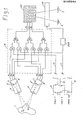
- An object field 1 with two spaced points A and B is imaged onto two photo cathodes 2 and 3 of the video cameras 4 and 5, respectively. Due to changes in perspective, the images A' and B' of points A and B are further apart on cathode 2 than their counterparts A" and B" on photocathode 3. For a stereoscopic image to be observed, the viewer's left eye 6 must see the image received by camera 5, whereas the right eye 7 must see that received by camera 4.
- Each camera has a red, green and blue signal (RGB) and the rasters corresponding to each are synchronised by a timing pulse (frame sync) 8 typically repeated at least 25 (or 30) times per second.
- RGB red, green and blue signal
- frame sync timing pulse
- circuit 9 which is illustrated diagrammatically as a series of AND and OR gates, each of which is capable of transmitting analogue video signals.
- Gates 10, 13 and 15 are enabled by a gating signal applied to line 16 or gates 11, 12 and 14 are enabled by a gating signal applied to line 17.
- the transmitted video signal components are passed by gates 18, 19 and 20 respect- i vely to emerge on lines R3, G3 and B3 respectively.
- the signals appearing on R3, G3 and B3 are either the red signal ( R1 ) from camera 4 together with the green and blue signals (G2 and B2) from camera 5 or, alternatively, the red signal (R2) from camera 5 together with the green and blue signals (G1 and B1) from camera 4.
- the timing of the gating signals corresponds to that of the two interlaced fields of the total video raster, shown as 21 (field A) and 22 (field B).
- H (High) means that the gates are enabled, whereas L (Low) means that they are blocked.
- Signals 21 and 22 could, if desired, change at the end of every line scan or on some other timing basis.
- the composite video signal (R3, G3, B3) is fed, together with the sync pulse 8 to a colour raster display 23 on which the two fields are shown diagramm- atioally as solid lines (Field A) and broken lines (Field B) respectively.
- the viewer sees the display screen through one of a number of possible viewing means 24, which are typically driven through an amplifier 24A in synchronism with gating signal 22. These ensure that each eye first sees the appropriate information contained in Field A and then, a short time later, there is a switch to Field B.
- the left eye 6 first sees the information contained in field A which corresponds to the left perspective (G2 and B2) while the right eye 7 sees the information contained in Field A which corresponds to the right perspective (R1). Then during Field B, the left eye 6 sees R2 and the right eye 7 sees G1 and B1.
- the rapidity with which the two fields are interchanged ensures that the eyes are not bothered by flickering effects.
- a motor 25 drives two substantially identical transparent tubular cylinders 26 and 27.
- Cylinder 27 is shown in section in Figure 2B, as seen from the right hand side of the viewing means.
- the cylinder 27 has two 180 0 sectors 28 (shown solid) and 29.
- Sector 28 transmits red and blocks blue and green whereas sector 29 transmits blue and green whilst blocking red.
- the two cylinders 26 and 27 are rotated in the same direction but when the red sector of cylinder 26 is facing the viewer's left eye 30, the blue-green transmitting sector of cylinder 27 is facing the viewer's right eye 31.
- Cylinder 32 is lying with its longitudinal axis parallel to the axis of rotation of cylinder 26.
- the outer periphery at the left-hand end is stepped for location against fixed walls W 1 , W 2 of the viewing means.
- the cylinder transmits red, blue and green light and has a sloped end-surface 33 at its right-hand side cut at 45° to provide an internally reflecting surface.
- Light from the screen 23 ( Figure 1) enters the cylinder 32 at its left flat end surface 34. End 34 could be curved to increase or decrease the size of the image.
- Solid cylinder 32 allows eye 30 to view the scene in front of the viewer via lens 35 (also shown in section in the side view), cylinder 26, reflecting surface 33, end surface 34 and via an auxiliary mirror 36 (part shown).
- Transparent semi-cylinder 37, corresponding to eye 31, has an equivalent auxiliary mirror 38.
- Auxiliary mirrors 36 and 38 may typically be folded inwards when not in use.
- the spaces adjacent the 45° reflecting surface of the two semicylinders 32, 37 are used to mount additional bearings 39 and 40 which are anchored to the corresponding semi-cylinder at points 41 and 42 (shown in section), outside the optically useful areas of the reflecting surfaces.
- Drive electronics 43 mounted adjacent the motor 25 and controlled by the output of amplifier 24A ensures that during Field A, left eye 30 views the screen through the green and blue transmitting sector of cylinder 26, and right eye 31 views the screen through the red sector of cylinder 27.
- Field B the cylinders 26 and 27 are rotated through 180° from their equivalent positions during Field A and each eye views a complementary part of the spectrum.
- a recess 44 shown as a broken line in the side view, allows the apparatus to accommodate the viewer's nose, and to be mounted in a natural "spectacle” position.
- An alternative to the two rotating tubular cylinders is an arrangement employing two contra- rotating discs, one for each eye.
- FIG. 3A A second embodiment of the invention, in which the viewer does not need to wear any special viewing apparatus to perceive depth is illustrated with reference to Figures 3A and 3B.
- the screen of a cathode ray tube is provided with alternating bands of phosphor on the inside of a fibre optic face plate 45.
- Stripes 46 contain blue and green phosphors, whereas stripes 47 are red emitting.
- Viewing means comprising a pair of lenticular screens, shown in section in Figure 3A, are mounted in front of the image formed on the face plate 45.
- the concave lens elements of screen 48 act in conjunction with their convex counterparts of screen 49 so that the front of the face plate 45 is at their combined focus.
- a small lateral movement of screen 48 effected by solenoid 50 causes a shift in the area behind each lenticule seen by each of the viewer's eyes 51 (left) and 52 (right).
- the lenticular screen 48 is split vertically into four sections 53, 54, 55 and 56 as shown in the front view in Figure 3B, each being independently movable by a corresponding solenoid shown schematically as rectangles 57.
- Four sinusoidal signals, (not shown) derived from the frame synchronising signals of the cathode ray tube and each 45° out of phase with its nearest neighbour and of a frequency equal to the frame rate of the raster displayed on the cathode ray tube, are applied to the four respective concave lenticular components.
- the amplitude and phase of motion are such that during Field A, the left eye 51 sees the blue and green regions of the face plate 45, whereas the right eye sees the red regions.
- the movement of each respective section reaches its maximum displacement either presenting the red or green/blue regions as appropriate to each eye.
- the width of a single lenticule at the screen will depend on the size and resolution of the display. It will typically be in the range 0.3mm to 1.5mm.
- FIG. 4A A further embodiment of the invention which requires no fixed viewing position, and only the wearing of simple polarising spectacles is illustrated with reference to Figure 4A.
- the viewer 58 wears simple polarising spectacles 59, and views a conventional colour video screen 60 through an opto-mechanical viewing device 61.
- Light from screen 60 passes through entrance window 62 of device 61 which acts as a plane polariser.
- a specially adapted continuous loop 63 of transparent material is kept in motion by rollers 64, 65, 66 and 67, so that light passes through the loop twice, once through material 68 moving to the left as seen in the Figure, and once through material 69 moving to the right.
- a detail 70 of this arrangement is shown in Figure 4B and region P is shown in elevation 71, Figure 4C.
- the continuous loop consists of pairs of narrow stripes 72, 73 which transmit either red (72) or blue/green (73). Alternate pairs of red and blue/green stripes are provided with a layer of material 74, such as the nematic twisted crystal used in liquid crystal displays, which rotates the plane of polarisation of the transmitted light by 90°. The remaining pairs located between pairs provided with material 74 transmit without such a rotation. The effect of light passing successively through two 90° rotations is equivalent to a zero effect. When two red stripes coincide for material moving to the left and right, and the corresponding red stripes each have a 90° rotation associated, then all red stripes will transmit without a net rotation.
- the detail 71 in Figure 4C shows how the stripes of alternating transmission characteristics are tipped to the left (as seen from the viewer's position at the front) on portion 68 (moving to the left) and to the right on portion 69 (moving to the right).
- Regions of coincidence 75 and 76 are alternatively red or blue/green transmitting and travel in a downward direction as seen from the front.
- the two states of plane polarisation corresponding to red or blue/green are altered to left or right circular or elliptical polarisation.
- a movement of left and right moving material of one coloured stripe width will completely switch the direction of circular polarisation corresponding to red or blue/green and is synchronised to correspond to a change from Field A to Field B.
- the downward motion of the region of coincidence is made to correspond to that of the vertical scan rate of the raster by setting the angle of tip correctly.
- Each spectacle window 78 consists, as shown in Figure 4D, of a quarter wave plate 79 and appropriate plane polarising element 80 to ensure that each eye receives only left or right circularly/elliptically polarised light.
- the drive means (not shown) for the loop 63 is controlled by the frame synchronising pulses of the cathode ray tube 60 and by a light transmitter/receiver pair 81 which detects the position of the loop 63, to synchronise the motion of loop 63 to the frame rate of the raster.
- the situation is reversed as the plane of polarisation of the plane polarising layer 80 is normal to that of the other layer in the left window and a blue/green image can be seen.
- the loop is synchronised with the frame rate of the raster so that the left eye constantily sees an image from one perspective and the right eye see a different perspective.
- Perfect circular polarisation is not necessary and in practice some ellipticity will be present.
- the requirement is for the quarter wave plates to have matching and opposite characteristics.
- the width of the stripes of colour filter material will depend as in the lenticular case on the size and resolution of the display. Similar dimensions would be employed.
- An alternative and simple variation of the above embodiment of the invention which requires only the wearing of polarising spectacles, comprises two striped sheets positioned face to face and in close proximity in front of the display screen.
- the first sheet comprises parallel vertical stripes of filter material arranged alternately to transmit red and blue/green light.
- the second sheet has matching stripes of polarising material alternate ones of which polarise light from the screen in one direction and the other ones of which polarise light in the orthogonal direction.
- the invention as described deals with the display of stereoscopic images on a screen in which different colour components of the same perspective are displayed alternatively and colour components of each of the two perspectives are displayed together.
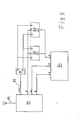
- an encoded (PAL, SECAM or NTSC) signal is received by aerial 82 and decoded into R, G and B components and a sync pulse by decoder 83. Two of these signals (G and B) are fed directly to the display screen 84.
- the R component is stored in a video frame (strictly speaking this should be video field) buffer.
- two video buffers are employed and may alternately be set to read (store) data or to write (display) data.
- the outputs of flip flop 85 which is complemented by field sync 86, cause either video buffer 87 or video buffer 88 to be selected for reading or writing.
- the outputs of buffers 87 and 88 are ORed together and the combination drives the R input of the display screen.
- FIG. 6A An alternative to the embodiment illustrated with reference to Figure 2A is shown in two forms in Figure 6A.
- a pair of spectacles may be constructed operating with either electro-optical shutter means or mechanical shutter means.
- FIG 6A both alternatives are illustrated by showing the window for the right eye in its electro-optic form, whereas that for the left eye is shown as an exploded mechanical assembly.
- an alternating array of red transmitting stripes 89 and blue/green transmitting stripes 90 are situated immediately behind a slotted lightweight shutter plate 91 which may be rapidly oscillated by an actuator 92 which is fed with electrical signals synchronised to the frame rate of the system.
- the whole assembly is shown as an exploded view.
- plate 91 runs in two grooves at the top and bottom of the striped array. For reasons of clarity only the lower groove 91A is shown. During one field the slots are aligned with stripes 89 whilst during the following field stripes 90 are allowed to pass light.
- the striped filter material 93 is situated behind a transparent sheet electrode 94 which forms part of a sandwich comprising two other electrodes 95 and 96 which are electrically isolated from each other and each of which has a series of fingers 95A and 96A respectively.
- the fingers 95A are positioned in front of all the stripes of one colour of filter material and the fingers 95B are positioned in front of the other stripes of colour filter material.
- Sandwiched between the electrode 94 and the electrodes 95, 96 is a layer of liquid crystal material 97. To complete the assembly it is normal to use polarising material on both sides of the total sandwich.
- Figure 6B shows these elements in section as layers 93A and 93B.
- the plane of polarisation of light passing through electrodes 94 and 95 will be altered by the voltage between them. The same is true for light passing through electrodes 94 and 96.
- red light may be transmitted whilst green and blue is blocked and vice versa .
- the slots or stripes in both mechanical and electro-optic embodiments would typically have a width of between 0.4mm to 1mm.
- the signals controlling the mechanical or electro-optical shutter means are derived from signals produced in synchronism with the production of the frames or fields of the image.
- liquid crystals employing a longitudinal field effect have been illustrated, other forms of electro-optic structure may be used.
- a good example of such an alternative is lanthanum doped lead Zirconate Titanate (PLZT) which, given a transverse field between adjacent narrow electrodes, will provide similar results. Its advantage compared to liquid crystal is its speed, but at a price premium.
- the embodiments described so far relate to special screens and/or viewing means adapted to switch the correct components of the displayed image to each of the viewer's eyes.
- the embodiment illustrated with reference to Figure 4 required the viewer to wear simple polarising glasses, whilst a colour selective polarising system is placed between the viewer and a conventional television soreen.
- polarising elements awitohable between alternate time periods may be placed in the light path before this reaches the display screen.
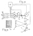
- One example of such a system uses a laser light source for each of the the three primary oolours, red, green, and blue. This is illustrated with reference to Figures 7A and 7B.
- Three laser sources 98 (red), 99 (green) and 100 (blue) are used. In practice these may be derived from one or two laser systems.
- an Argon laser typically provides green and blue wavelengths. Each laser is assumed to have a polarised output which may be modulated independently.
- a computer 101 provides drive signals to acousto-optic modulators 102, 103 and 104.
- the green output beam has its plane of polarisation twisted by 90° with respect to the red and blue beams. In this embodiment this is accomplished by a half wave plate 105.
- the three primary colours are combined into one composite beam by mirrors 106 and 107 and two dichroic elements 108 and 109.
- An electro-optic cell 110 in the path of the beam switches the polarisation axes of all components at the beginning of each field under the control of computer 101.
- Field A the red and blue components are vertically polarised whilst green has horizontal polarisation
- cell 110 causes the inverse to be true in Field B.
- the composite beam is scanned in the form of a raster on screen 111 shown in Figure 7B in front elevation 112. This is achieved by a spinning polygonal mirror 113 and an oscillating mirror 114 each of which receives signals from computer 101. Relay optics 115 ensures maximum efficiency in this process.
- the viewer 116 observes screen 111 through polarised spectacles 117, each window of which selects orthogonally polarised components.
- cell 110 may equally well have been replaced by three elements acting in parallel and placed in the component beams before their recombination.
- an electro-mechanical polarisation switch could replace cell 110.
- the two spectral components switched between fields to each eye are the red and blue on the one hand and the green on the other.
- computer 101 could in practice be a video signal receiver or a device such as a video cassette recorder.
- a video recording for displaying stereoscopic images in accordance with the invention is illustrated with reference to Figure 8.
- This shows in diagrammatic form a section of a video tape 118 on which magnetic information has been recorded.
- Tape control information is contained in a stripe 119, whereas audio information is recorded on tracks 120 and 121.
- Video signals are recorded on a diagonal format, three such tracks being illustrated. Each diagonally recorded track comprises video signals for a single field of the image.
- track 122 contains the red and blue spectral components for the left eye together with the green component for the right eye and comprises the Field A signal.
- Track 123 contains the red and blue components for the right eye together with the green component for the left eye and comprises the Field B signal.
- Track 124 comprises the first field of the next video frame.
- the data may be recorded on a video disc or in digital form in a ROM (Read Only Memory) or on a computer tape or disc.
- the format in which it is recorded may be tailored to be suitable for use by a computer program for displaying stereoscopic images.
- the record may form part of a video game.
- the record need not be on a magnetic medium but may comprise photographic film.
- Lenticular screens may be used in conjunction with conventional TV screens or adapted screens may be combined with polarising arrangements as described above.
- the principles of the invention may be applied to cinematography, in which successive frames are treated in the way that alternate fields are in the examples given. It will also be apparent that switching from one part of the spectrum to another need not be done at any particular rate, providing the viewing mechanism does so on a synchronous basis. In this case, line frequency may replace alternate fields.
- the division of the spectrum need not be as described and other permutations are permissible.
- the arrangement shown in Figure 3 may be modified for use with a conventional television screen.
- the elements indicated by reference numbers 46 and 47 would be constituted by a filter having stripes alternate ones of which pass one of the spectral component and the others of which pass the other spectral component.
- the fibre-optic face plate may be omitted.
- the device modified in this way may be placed close to the television screen and stereoscopic images viewed provided the images produced on the television screen are in accordance with the teachings of the present invention.
- both in this arrangement and in the arrangement shown in Figure 3 it would be possible to employ just a single lenticular lens sheet but in this case a larger amplitude of movement would be required.
- the system is not limited to the display of colour images, and may be used to provide a substantially flicker free display of a black and white picture by feeding the same black and white video signal to the R, G and B inputs of a colour display system. Each perspective would be displayed in a subset of these colours in any given field.
Abstract
Description
- The present invention relates to a method and apparatus for producing stereoscopic images.
- The principle of stereoscopic vision is well understood. At the most basic level, each of the viewer's two eyes must perceive the subject matter to be viewed from a slightly different perspective. That is to say that, although the differences are generally quite subtle, each eye receives a different image.
- Several methods are commonly used to produce stereoscopic images. On the one hand these include the use of direction selective screens onto which two or more images may be projected simultaneously. Depending on the viewer's position, a different image may be observed by each eye. Where only two images are required, it is common practice to use polarising techniques. Each image is projected with a characteristic polarisation and when viewing through complementary polarising viewing spectacles, each eye only sees the picture intended for its reception.
- In television systems, it is possible to use projection techniques together with two or more complete display channels, typically one or more electronic display such as a Cathode Ray Tube (CRT) for each perspective to be displayed. However these systems tend to be costly because of the large amount of equipment needed. There may also be difficulty in obtaining proper alignment of the total system. In order to overcome the need for more than one image creation surface such as the phosphor coated screen of a colour CRT, anaglyph techniques have been used with some modest success. The anaglyph system, as practised in the current art, depends on the use of complementary colour filters placed in front of each eye. For example a red transmitting filter may be used for the left eye, and a blue and green transmitting filter used for the right eye. After each eye has become accustomed to the particular colour bias, and by displaying the left hand perspective of the subject in red and the right hand perspective in blue-green, a reasonable stereoscopic image may be observed. However, because each eye is observing a very restricted portion of th full colour spectrum, only limited colour information can be added to what generally appears as a lightly tinted picture.
- A further proposal which has been made in the prior art is to produce on a screen full colour images of the left and right perspectives alternately. The screen is viewed through spectacles which permit each eye to receive only the image of the appropriate perspective. This system is described in, for example, US patent Nos.3621127 (Hope) and 4021846 (Roese) and in UK patent No.1523436 (Mears). The problem with this system is that substantial flicker is produced because the image received by each eye alternates with periods of darkness.
- An object of the invention is to provide a method and apparatus for producing a stereoscopic image in which the viewer is provided with an image which may include a substantially full range of colour information for each eye substantially without flicker. Another object of the invention is to provide such an apparatus which, at least in certain forms, may be produced at relatively low cost.
- The invention provides in one embodiment apparatus comprising a display screen on which at least two perspectives of an object field are displayed so that in use, the components of the colour spectrum used to display one perspective are, at a given instant, generally complementary to the components of the colour spectrum used to display another perspective whilst, averaged over a period of time, each said perspective is displayed using a generally representative set of components of the full spectrum of colour relative to the object field to be displayed stereoscopically.
- The invention also provides in another embodiment apparatus including a display screen and viewing means adapted to transmit components of the colour spectrum corresponding to one perspective at a given instant to one eye of a viewer and components of the colour spectrum corresponding to a second perspective at that instant to the other eye of the viewer.
- For example, a left-perspective view of an object in an object field and a right-perspective view may be displayed on a screen, with the right-perspective displayed in red and the left-perspective displayed in complementary blue-green. Rapid switching between the two produces a substantially full spectrum of colour for each perspective. In order to view a stereoscopic image on the screen, viewing means are positioned to intercept rays from the screen. The viewing means enables the left eye to see the left perspective of the object and the right eye to see the right perspective. The colours supplied to each eye at a given instant are complementary to those supplied to the other eye and are switched rapidly in synchronism with the alternating colours of each view on the screen. The rapidity of the switching can be fast enough so that a viewer is not aware of flickering. At one instant the left eye sees the left-perspective in blue-green and the right eye sees the right-perspective in red and at the next instant the situation is reversed, the effect being that of a substantially full-colour stereoscopic image.
- Thus, in an embodiment of the invention stereoscopic apparatus comprises a display screen for displaying a first perspective view of an object field having a first set of colour components and a second perspective view of the object field having a second complementary set of colour components, means for rapidly alternating the first and second sets of colour components, and viewing means positioned to intercept rays from the screen and adapted to transmit to a viewer to enable one eye of the viewer to see the first perspective view and the other eye to see the second perspective view and to synchronise the colour components received by each eye with the alternations of the sets of colour components at the display screen thereby, in use, providing the viewer with a stereoscopic image of the object field.
- The viewing means may comprise apparatus, placed in the path between the viewer's eyes and the display screen, which includes filter array means, consisting of a repetitive array of transmission filter elements which individually either block or transmit a specific part of the colour spectrum corresponding to the object field to be viewed stereoscopically, and, associated with said filter array means processing array means, consisting of a matching array of polarising elements or lens elements, so that, in use, the light passing via each said filter element and corresponding processing elment is provided, at a given instant, with polarisation or directional characteristics specific to the perspective of the object field being displayed by use of the components of the colour spectrum transmitted by said filter element at said given instant.
- The system may include light array means, consisting of a repetitive array of light emitting elements each of which emits radiation within a specific part of the colour spectrum relative to an object field to be displayed stereoscopically, so that, in use and at a given instant, each said element only radiates light corresponding to a specific perspective of said object field, and processing array means, consisting of a matching array of polarising elements or lens elements so that, in use, light passing through each said processing element from a corresponding light emitting element is provided with polarisation or directional characteristics specific to the perspective of said object field being displayed by use of the components of the colour spectrum emitted by said light emitting element at said given instant, and electronic and/or mechanical means to maintain the polarisation or directional characteristics specific to a particular perspective of said objest field irrespective of the spectral component used to display said perspective at any given instant.
- The invention will now be described by way of example with reference to the accompanying drawings, in which:
- Figure 1 illustrates schematically an arrangement in which a colour video signal for a raster display system is generated;
- Figures 2A and 2B show respectively in plan and sectional side elevation a device constructed in accordance with one embodiment of the invention and suitable for use by a viewer to view a stereoscopic image displayed on a screen;
- Figures 3A and 3B show respectively in horizontal section and front elevation a display screen and viewing means constructed in accordance with a second embodiment of the invention and suitable for viewing a stereoscopic image without the aid of any special viewing device worn by the viewer;
- Figures 4A, 4B, 4C and 4D illustrate a third embodiment of the invention in which the viewer needs only passive polarising glasses; Figure 4A shows the arrangement in plan, Figure 4D showing an enlarged section through one side of the spectacles; Figure 4B shows a small region of the main assembly in horizontal section and Figure 4C shows this same region in front elevation;
- Figure 5 illustrates a further embodiment of the invention in which a PAL, NTSC or SECAM colour signal is suitably processed for subsequent display in a form in accordance with the invention;
- Figure 6A illustrates diagrammatically and in two halves, two alternative embodiments of viewing spectacles constructed in accordance with the invention;
- Figure 6B shows in horizontal section a small portion of the right eye's assembly of Figure 6A;
- Figure 7A illustrates schematically a laser raster display for displaying stereoscopic images in accordance with the invention;
- Figure 7B shows the screen of Figure 7A with displayed raster in front elevation;
- Figure 8 illustrates diagrammatically a video recording produced in accordance with the invention.
- A method for combining two colour video signals, one corresponding to each of two perspectives of an object field and applying the composite signal to a display screen is illustrated with reference to Figure 1.
- An
object field 1 with two spaced points A and B is imaged onto twophoto cathodes video cameras 4 and 5, respectively. Due to changes in perspective, the images A' and B' of points A and B are further apart oncathode 2 than their counterparts A" and B" onphotocathode 3. For a stereoscopic image to be observed, the viewer's left eye 6 must see the image received by camera 5, whereas the right eye 7 must see that received bycamera 4. - Each camera has a red, green and blue signal (RGB) and the rasters corresponding to each are synchronised by a timing pulse (frame sync) 8 typically repeated at least 25 (or 30) times per second.
- The RGB signals from both cameras are accepted by circuit 9 which is illustrated diagrammatically as a series of AND and OR gates, each of which is capable of transmitting analogue video signals.
Gates line 16 orgates line 17. The transmitted video signal components are passed bygates 18, 19 and 20 respect- ively to emerge on lines R3, G3 and B3 respectively. - By ensuring that the gating signals applied to
lines camera 4 together with the green and blue signals (G2 and B2) from camera 5 or, alternatively, the red signal (R2) from camera 5 together with the green and blue signals (G1 and B1) fromcamera 4. - Typically, the timing of the gating signals corresponds to that of the two interlaced fields of the total video raster, shown as 21 (field A) and 22 (field B). H (High) means that the gates are enabled, whereas L (Low) means that they are blocked.
Signals - The composite video signal (R3, G3, B3) is fed, together with the
sync pulse 8 to acolour raster display 23 on which the two fields are shown diagramm- atioally as solid lines (Field A) and broken lines (Field B) respectively. - The viewer sees the display screen through one of a number of possible viewing means 24, which are typically driven through an
amplifier 24A in synchronism withgating signal 22. These ensure that each eye first sees the appropriate information contained in Field A and then, a short time later, there is a switch to Field B. Thus, the left eye 6 first sees the information contained in field A which corresponds to the left perspective (G2 and B2) while the right eye 7 sees the information contained in Field A which corresponds to the right perspective (R1). Then during Field B, the left eye 6 sees R2 and the right eye 7 sees G1 and B1. The rapidity with which the two fields are interchanged ensures that the eyes are not bothered by flickering effects. - One possible viewing means is illustrated with reference to Figure 2A. A
motor 25 drives two substantially identical transparenttubular cylinders Cylinder 27 is shown in section in Figure 2B, as seen from the right hand side of the viewing means. Thecylinder 27 has two 1800 sectors 28 (shown solid) and 29.Sector 28 transmits red and blocks blue and green whereassector 29 transmits blue and green whilst blocking red. The twocylinders cylinder 26 is facing the viewer'sleft eye 30, the blue-green transmitting sector ofcylinder 27 is facing the viewer'sright eye 31. - Inside each tubular cylinder there is a solid, stationary, clear
transparent semi-cylinder 32, 37. The left and right sides of the viewing means are similar, and the left side only will be described.Cylinder 32 is lying with its longitudinal axis parallel to the axis of rotation ofcylinder 26. The outer periphery at the left-hand end is stepped for location against fixed walls W1, W2 of the viewing means. The cylinder transmits red, blue and green light and has a sloped end-surface 33 at its right-hand side cut at 45° to provide an internally reflecting surface. Light from the screen 23 (Figure 1) enters thecylinder 32 at its leftflat end surface 34.End 34 could be curved to increase or decrease the size of the image.Solid cylinder 32 allowseye 30 to view the scene in front of the viewer via lens 35 (also shown in section in the side view),cylinder 26, reflecting surface 33,end surface 34 and via an auxiliary mirror 36 (part shown). Transparent semi-cylinder 37, corresponding to eye 31, has an equivalentauxiliary mirror 38. Auxiliary mirrors 36 and 38 may typically be folded inwards when not in use. - In order to provide an axis for each rotating hollow cylinder with some rigidity, the spaces adjacent the 45° reflecting surface of the two
semicylinders 32, 37 are used to mountadditional bearings 39 and 40 which are anchored to the corresponding semi-cylinder atpoints 41 and 42 (shown in section), outside the optically useful areas of the reflecting surfaces. - Drive
electronics 43 mounted adjacent themotor 25 and controlled by the output ofamplifier 24A ensures that during Field A, lefteye 30 views the screen through the green and blue transmitting sector ofcylinder 26, andright eye 31 views the screen through the red sector ofcylinder 27. By rotating the tops of the cylinders -towards the viewer, transitions between red and blue/green transmission occur from top to bottom of the field of view which makes synchronisation less critical as it follows the direction of the raster scan pattern on the screen. During Field B, thecylinders - A
recess 44, shown as a broken line in the side view, allows the apparatus to accommodate the viewer's nose, and to be mounted in a natural "spectacle" position. - An alternative to the two rotating tubular cylinders is an arrangement employing two contra- rotating discs, one for each eye.
- A second embodiment of the invention, in which the viewer does not need to wear any special viewing apparatus to perceive depth is illustrated with reference to Figures 3A and 3B.
- The screen of a cathode ray tube is provided with alternating bands of phosphor on the inside of a fibre
optic face plate 45.Stripes 46 contain blue and green phosphors, whereasstripes 47 are red emitting. - Viewing means, comprising a pair of lenticular screens, shown in section in Figure 3A, are mounted in front of the image formed on the
face plate 45. The concave lens elements ofscreen 48 act in conjunction with their convex counterparts ofscreen 49 so that the front of theface plate 45 is at their combined focus. A small lateral movement ofscreen 48 effected bysolenoid 50 causes a shift in the area behind each lenticule seen by each of the viewer's eyes 51 (left) and 52 (right). - The
lenticular screen 48 is split vertically into foursections rectangles 57. Four sinusoidal signals, (not shown) derived from the frame synchronising signals of the cathode ray tube and each 45° out of phase with its nearest neighbour and of a frequency equal to the frame rate of the raster displayed on the cathode ray tube, are applied to the four respective concave lenticular components. The amplitude and phase of motion are such that during Field A, theleft eye 51 sees the blue and green regions of theface plate 45, whereas the right eye sees the red regions. As the raster proceeds from the top of the screen (section 53) to the bottom (section 56) the movement of each respective section reaches its maximum displacement either presenting the red or green/blue regions as appropriate to each eye. - There will be several viewing positions which may be adopted by the viewer to perceive correct orthoscopic images, but each is relatively well defined in space. The width of a single lenticule at the screen will depend on the size and resolution of the display. It will typically be in the range 0.3mm to 1.5mm.
- A further embodiment of the invention which requires no fixed viewing position, and only the wearing of simple polarising spectacles is illustrated with reference to Figure 4A.
- The
viewer 58 wearssimple polarising spectacles 59, and views a conventionalcolour video screen 60 through an opto-mechanical viewing device 61. Light fromscreen 60 passes throughentrance window 62 ofdevice 61 which acts as a plane polariser. A specially adaptedcontinuous loop 63 of transparent material is kept in motion byrollers material 68 moving to the left as seen in the Figure, and once throughmaterial 69 moving to the right. Adetail 70 of this arrangement is shown in Figure 4B and region P is shown inelevation 71, Figure 4C. - The continuous loop consists of pairs of
narrow stripes material 74, such as the nematic twisted crystal used in liquid crystal displays, which rotates the plane of polarisation of the transmitted light by 90°. The remaining pairs located between pairs provided withmaterial 74 transmit without such a rotation. The effect of light passing successively through two 90° rotations is equivalent to a zero effect. When two red stripes coincide for material moving to the left and right, and the corresponding red stripes each have a 90° rotation associated, then all red stripes will transmit without a net rotation. At the same time, all light passing through green/blue stripes will suffer only one 90° rotation, either through the material moving to the left or that moving to the right. As the loop continues to move, this condition will alternate and the red polarisation will become rotated whereas green/blue will remain unaltered. - The
detail 71 in Figure 4C shows how the stripes of alternating transmission characteristics are tipped to the left (as seen from the viewer's position at the front) on portion 68 (moving to the left) and to the right on portion 69 (moving to the right). Regions ofcoincidence wave retardation plate 77, the two states of plane polarisation corresponding to red or blue/green are altered to left or right circular or elliptical polarisation. A movement of left and right moving material of one coloured stripe width will completely switch the direction of circular polarisation corresponding to red or blue/green and is synchronised to correspond to a change from Field A to Field B. - The downward motion of the region of coincidence is made to correspond to that of the vertical scan rate of the raster by setting the angle of tip correctly.
- Each
spectacle window 78 consists, as shown in Figure 4D, of aquarter wave plate 79 and appropriate plane polarising element 80 to ensure that each eye receives only left or right circularly/elliptically polarised light. The drive means (not shown) for theloop 63 is controlled by the frame synchronising pulses of thecathode ray tube 60 and by a light transmitter/receiver pair 81 which detects the position of theloop 63, to synchronise the motion ofloop 63 to the frame rate of the raster. - The operation is as follows. Light from
screen 60 becomes plane polarised in one direction in passing throughwindow 62. The polarisation of red light transmitted at a given instant by the loop is unaltered because it suffers two 90° rotations, whilst the polarisation of blue/green light is rotated through 90°.Quarter wave plate 77 causes the red and blue/green light to become oppositely circularly polarised. On reaching the left spectacle window, quarter-wave plate layer 79 of that window converts the two types of circularly polarised light to plane polarised beams, one red and one blue/green, differentiated by 90°. Plane polarising layer 80 transmits one only of the beams so that the left eye sees only, say a red image. For the right eye the situation is reversed as the plane of polarisation of the plane polarising layer 80 is normal to that of the other layer in the left window and a blue/green image can be seen. As the loop moves, the situation reverses so that the left eye sees a blue/green image and the right eye a red one. The loop is synchronised with the frame rate of the raster so that the left eye constantily sees an image from one perspective and the right eye see a different perspective. Perfect circular polarisation is not necessary and in practice some ellipticity will be present. The requirement is for the quarter wave plates to have matching and opposite characteristics. The width of the stripes of colour filter material will depend as in the lenticular case on the size and resolution of the display. Similar dimensions would be employed. - An alternative and simple variation of the above embodiment of the invention, which requires only the wearing of polarising spectacles, comprises two striped sheets positioned face to face and in close proximity in front of the display screen. The first sheet comprises parallel vertical stripes of filter material arranged alternately to transmit red and blue/green light. The second sheet has matching stripes of polarising material alternate ones of which polarise light from the screen in one direction and the other ones of which polarise light in the orthogonal direction. By moving the two sheets with respect to each other in their own plane in a horizontal direction, the complimentary spectral components have their polarisation vector switched between fields and always orthogonal one to the other.
- The invention as described deals with the display of stereoscopic images on a screen in which different colour components of the same perspective are displayed alternatively and colour components of each of the two perspectives are displayed together.
- When the invention is used in a TV transmission environment, it is often convenient to employ PAL, NTSC or SECAM colour encoding techniques. In these systems, R, G and B signals are produced by decoding the luminance and chrominance signals and there is a risk of noise on the received signal causing false colour to be displayed. In fact, averaging techniques and effects make the eye tolerant to such errors, but the stereoscopic display technique proposed by the invention can be substantially degraded by a mixing between the two perspectives.
- It is therefore preferable to transmit the entire first perspective in Field A (with all its colour components) and the entire second perspective in Field B. The display of this information, following decoding is arranged by use of storage techniques to be colour sequential for each perspective.
- In Figure 5 an encoded (PAL, SECAM or NTSC) signal is received by aerial 82 and decoded into R, G and B components and a sync pulse by
decoder 83. Two of these signals (G and B) are fed directly to thedisplay screen 84. The R component is stored in a video frame (strictly speaking this should be video field) buffer. - In the embodiment shown, two video buffers are employed and may alternately be set to read (store) data or to write (display) data. The outputs of
flip flop 85, which is complemented byfield sync 86, cause eithervideo buffer 87 or video buffer 88 to be selected for reading or writing. - The outputs of
buffers 87 and 88 are ORed together and the combination drives the R input of the display screen. - The result is that, although the signal is transmitted in a full field sequential mode, it is displayed in accordance with the invention in colour sequential manner and a substantially lower level of flicker is achieved.
- An alternative to the embodiment illustrated with reference to Figure 2A is shown in two forms in Figure 6A. A pair of spectacles may be constructed operating with either electro-optical shutter means or mechanical shutter means. In Figure 6A both alternatives are illustrated by showing the window for the right eye in its electro-optic form, whereas that for the left eye is shown as an exploded mechanical assembly.
- In the mechanical case an alternating array of red transmitting stripes 89 and blue/
green transmitting stripes 90 are situated immediately behind a slottedlightweight shutter plate 91 which may be rapidly oscillated by anactuator 92 which is fed with electrical signals synchronised to the frame rate of the system. The whole assembly is shown as an exploded view. Inpractice plate 91 runs in two grooves at the top and bottom of the striped array. For reasons of clarity only the lower groove 91A is shown. During one field the slots are aligned with stripes 89 whilst during thefollowing field stripes 90 are allowed to pass light. - In the electro-optio case, a similar result is achieved without mechanical movement. The
striped filter material 93 is situated behind atransparent sheet electrode 94 which forms part of a sandwich comprising twoother electrodes fingers fingers 95A are positioned in front of all the stripes of one colour of filter material and the fingers 95B are positioned in front of the other stripes of colour filter material. Sandwiched between theelectrode 94 and theelectrodes liquid crystal material 97. To complete the assembly it is normal to use polarising material on both sides of the total sandwich. Figure 6B shows these elements in section aslayers electrodes electrodes electrodes - Although liquid crystals employing a longitudinal field effect have been illustrated, other forms of electro-optic structure may be used. A good example of such an alternative is lanthanum doped lead Zirconate Titanate (PLZT) which, given a transverse field between adjacent narrow electrodes, will provide similar results. Its advantage compared to liquid crystal is its speed, but at a price premium.
- The embodiments described so far relate to special screens and/or viewing means adapted to switch the correct components of the displayed image to each of the viewer's eyes. The embodiment illustrated with reference to Figure 4 required the viewer to wear simple polarising glasses, whilst a colour selective polarising system is placed between the viewer and a conventional television soreen. In systems where the TV raster is generated by scanning a beam of light or on a small format, following which it is projected optically onto a large soreen, polarising elements awitohable between alternate time periods may be placed in the light path before this reaches the display screen. One example of such a system uses a laser light source for each of the the three primary oolours, red, green, and blue. This is illustrated with reference to Figures 7A and 7B.
- Three laser sources 98 (red), 99 (green) and 100 (blue) are used. In practice these may be derived from one or two laser systems. For example, an Argon laser typically provides green and blue wavelengths. Each laser is assumed to have a polarised output which may be modulated independently. A
computer 101 provides drive signals to acousto-optic modulators half wave plate 105. The three primary colours are combined into one composite beam bymirrors dichroic elements optic cell 110 in the path of the beam switches the polarisation axes of all components at the beginning of each field under the control ofcomputer 101. Thus, if in Field A the red and blue components are vertically polarised whilst green has horizontal polarisation,cell 110 causes the inverse to be true in Field B. - The composite beam is scanned in the form of a raster on screen 111 shown in Figure 7B in
front elevation 112. This is achieved by a spinningpolygonal mirror 113 and an oscillating mirror 114 each of which receives signals fromcomputer 101.Relay optics 115 ensures maximum efficiency in this process. Theviewer 116 observes screen 111 through polarisedspectacles 117, each window of which selects orthogonally polarised components. - Thus, one eye observes red and blue whilst the other observes green and this situation is reversed during the following field.
- It will be apparent that different arrangements are possible. For
instance cell 110 may equally well have been replaced by three elements acting in parallel and placed in the component beams before their recombination. Also, an electro-mechanical polarisation switch could replacecell 110. In this example, unlike previous embodiments, the two spectral components switched between fields to each eye are the red and blue on the one hand and the green on the other. It will also be apparent thatcomputer 101 could in practice be a video signal receiver or a device such as a video cassette recorder. - A video recording for displaying stereoscopic images in accordance with the invention is illustrated with reference to Figure 8. This shows in diagrammatic form a section of a
video tape 118 on which magnetic information has been recorded. Tape control information is contained in a stripe 119, whereas audio information is recorded ontracks Track 123 contains the red and blue components for the right eye together with the green component for the left eye and comprises the Field B signal.Track 124 comprises the first field of the next video frame. - It will be clear that other forms of record are possible. The data may be recorded on a video disc or in digital form in a ROM (Read Only Memory) or on a computer tape or disc. The format in which it is recorded may be tailored to be suitable for use by a computer program for displaying stereoscopic images. The record may form part of a video game.
- The record need not be on a magnetic medium but may comprise photographic film.
- It will be apparent that many variations to the various embodiments illustrated are possible. Lenticular screens may be used in conjunction with conventional TV screens or adapted screens may be combined with polarising arrangements as described above. The principles of the invention may be applied to cinematography, in which successive frames are treated in the way that alternate fields are in the examples given. It will also be apparent that switching from one part of the spectrum to another need not be done at any particular rate, providing the viewing mechanism does so on a synchronous basis. In this case, line frequency may replace alternate fields. Furthermore, the division of the spectrum need not be as described and other permutations are permissible.
- As a further embodiment of the invention, the arrangement shown in Figure 3 may be modified for use with a conventional television screen. In this modification, the elements indicated by
reference numbers - In fact, the system is not limited to the display of colour images, and may be used to provide a substantially flicker free display of a black and white picture by feeding the same black and white video signal to the R, G and B inputs of a colour display system. Each perspective would be displayed in a subset of these colours in any given field.
Claims (25)
Priority Applications (1)
| Application Number | Priority Date | Filing Date | Title |
|---|---|---|---|
| AT84305380T ATE32819T1 (en) | 1983-08-12 | 1984-08-07 | METHOD AND EQUIPMENT FOR GENERATION OF STEROSCOPIC IMAGES. |
Applications Claiming Priority (2)
| Application Number | Priority Date | Filing Date | Title |
|---|---|---|---|
| GB838321727A GB8321727D0 (en) | 1983-08-12 | 1983-08-12 | Producing stereoscopic images |
| GB8321727 | 1983-08-12 |
Publications (2)
| Publication Number | Publication Date |
|---|---|
| EP0135340A1 true EP0135340A1 (en) | 1985-03-27 |
| EP0135340B1 EP0135340B1 (en) | 1988-03-02 |
Family
ID=10547203
Family Applications (1)
| Application Number | Title | Priority Date | Filing Date |
|---|---|---|---|
| EP84305380A Expired EP0135340B1 (en) | 1983-08-12 | 1984-08-07 | Method and apparatus for producing stereoscopic images |
Country Status (5)
| Country | Link |
|---|---|
| US (2) | US4641178A (en) |
| EP (1) | EP0135340B1 (en) |
| AT (1) | ATE32819T1 (en) |
| DE (1) | DE3469668D1 (en) |
| GB (1) | GB8321727D0 (en) |
Cited By (4)
| Publication number | Priority date | Publication date | Assignee | Title |
|---|---|---|---|---|
| WO1998033331A1 (en) * | 1997-01-22 | 1998-07-30 | Dynamic Digital Depth Research Pty Ltd | Method and apparatus for producing stereoscopic images |
| GB2428153A (en) * | 2005-07-08 | 2007-01-17 | Sharp Kk | Interactive multiple view display |
| CN102638701A (en) * | 2011-02-15 | 2012-08-15 | 瑞昱半导体股份有限公司 | Display, image processing device and image processing method |
| EP2624573A1 (en) * | 2012-01-31 | 2013-08-07 | Funai Electric Advanced Applied Technology Research Institute Inc. | Laser scan type projector and three dimensional display system |
Families Citing this family (55)
| Publication number | Priority date | Publication date | Assignee | Title |
|---|---|---|---|---|
| GB8321727D0 (en) * | 1983-08-12 | 1983-09-14 | Brightad Ltd | Producing stereoscopic images |
| US4739418A (en) * | 1985-03-20 | 1988-04-19 | Victor Company Of Japan, Ltd. | Information signal recording disc recorded with stereoscopic television signal |
| US5036385A (en) * | 1986-03-07 | 1991-07-30 | Dimension Technologies, Inc. | Autostereoscopic display with multiple sets of blinking illuminating lines and light valve |
| US4829365A (en) * | 1986-03-07 | 1989-05-09 | Dimension Technologies, Inc. | Autostereoscopic display with illuminating lines, light valve and mask |
| JPS63116590A (en) * | 1986-11-04 | 1988-05-20 | Nippon Hoso Kyokai <Nhk> | Stereoscopic video disk record |
| KR930009882B1 (en) * | 1987-10-31 | 1993-10-12 | 주식회사 금성사 | Lcd projector driving device for high brightness |
| US4893898A (en) * | 1988-02-09 | 1990-01-16 | Beard Terry D | Low differential 3-D viewer glasses and method with spectral transmission properties to control relative intensities |
| US4827347A (en) * | 1988-08-22 | 1989-05-02 | Eastman Kodak Company | Electronic camera with proofing feature |
| US4853764A (en) * | 1988-09-16 | 1989-08-01 | Pedalo, Inc. | Method and apparatus for screenless panoramic stereo TV system |
| US4945407A (en) * | 1989-05-12 | 1990-07-31 | Winnek Douglas Fredwill | High definition, three-dimensional television |
| WO1991003133A1 (en) * | 1989-08-23 | 1991-03-07 | Sokolnichesky Tsentr Nttm G. Moskvy | Television device for demonstration of stereoscopic images |
| US4963959A (en) * | 1989-11-20 | 1990-10-16 | Drewlo Kenneth G | Three-dimensional cathode ray tube display |
| US5537144A (en) * | 1990-06-11 | 1996-07-16 | Revfo, Inc. | Electro-optical display system for visually displaying polarized spatially multiplexed images of 3-D objects for use in stereoscopically viewing the same with high image quality and resolution |
| US5327285A (en) | 1990-06-11 | 1994-07-05 | Faris Sadeg M | Methods for manufacturing micropolarizers |
| GB9027881D0 (en) * | 1990-12-21 | 1991-02-13 | Delta System Design Ltd | Improvements in 3d imaging systems |
| US5260773A (en) * | 1991-10-04 | 1993-11-09 | Matsushita Electric Corporation Of America | Color alternating 3-dimensional TV system |
| US5264964A (en) | 1991-12-18 | 1993-11-23 | Sades Faris | Multi-mode stereoscopic imaging system |
| US5903388A (en) | 1992-06-11 | 1999-05-11 | Sedlmayr Steven R | High efficiency electromagnetic beam projector and systems and method for implementation thereof |
| US5347644A (en) * | 1992-06-11 | 1994-09-13 | Sedlmayr Steven R | Three-dimensional image display device and systems and methods for implementation thereof |
| US5347433A (en) * | 1992-06-11 | 1994-09-13 | Sedlmayr Steven R | Collimated beam of light and systems and methods for implementation thereof |
| DE69422803T2 (en) * | 1993-03-03 | 2000-06-15 | Graham Stewart B Street | Image orientation and device |
| CN1068756C (en) * | 1993-10-08 | 2001-07-18 | 李昌 | Stereo television system |
| US6111598A (en) * | 1993-11-12 | 2000-08-29 | Peveo, Inc. | System and method for producing and displaying spectrally-multiplexed images of three-dimensional imagery for use in flicker-free stereoscopic viewing thereof |
| US5774261A (en) * | 1993-11-19 | 1998-06-30 | Terumo Kabushiki Kaisha | Image display system |
| EP0656730B1 (en) * | 1993-12-03 | 2000-04-26 | Terumo Kabushiki Kaisha | Stereoscopic image display system |
| JPH07222204A (en) * | 1994-02-07 | 1995-08-18 | Terumo Corp | Stereoscopic image display device |
| JPH07218864A (en) * | 1994-02-07 | 1995-08-18 | Terumo Corp | Three-dimensional image display device |
| JPH07226957A (en) * | 1994-02-09 | 1995-08-22 | Terumo Corp | Stereoscopic picture communication equipment |
| JPH07222866A (en) * | 1994-02-09 | 1995-08-22 | Terumo Corp | Stereoscopic image game machine |
| US6011580A (en) * | 1994-06-07 | 2000-01-04 | Terumo Kabushiki Kaisha | Image display apparatus |
| US5936774A (en) * | 1995-08-29 | 1999-08-10 | Street; Graham S. B. | Autostereoscopic display |
| US5737087A (en) * | 1995-09-29 | 1998-04-07 | Eastman Kodak Company | Motion-based hard copy imaging |
| DE19537356C1 (en) * | 1995-10-06 | 1996-12-05 | Ldt Gmbh & Co | Method of producing stereoscopic video picture |
| US6055012A (en) * | 1995-12-29 | 2000-04-25 | Lucent Technologies Inc. | Digital multi-view video compression with complexity and compatibility constraints |
| WO1997046029A1 (en) * | 1996-05-24 | 1997-12-04 | Reveo, Inc. | Flicker-free stereoscopic 3-d display system using spectral-multiplexing |
| WO1998049837A1 (en) * | 1997-04-30 | 1998-11-05 | Ldt Gmbh & Co. Laser-Display-Technologie Kg | Method and facility for light-beam projection of images on a screen |
| DE19808264C2 (en) * | 1997-04-30 | 2000-04-06 | Helmut Jorke | Method for producing stereocopic color images with high image contrast |
| KR100270804B1 (en) * | 1998-02-18 | 2000-11-01 | 박남은 | Apparatus for implementing stereoscopic images in a computer system using crt monitor |
| US6816158B1 (en) | 1998-10-30 | 2004-11-09 | Lemelson Jerome H | Three-dimensional display system |
| DE602004026791D1 (en) * | 2003-10-21 | 2010-06-02 | Barco Nv | Method and device for carrying out a stereoscopic image display on the basis of color-selective filters |
| GB0329312D0 (en) * | 2003-12-18 | 2004-01-21 | Univ Durham | Mapping perceived depth to regions of interest in stereoscopic images |
| US20060072005A1 (en) * | 2004-10-06 | 2006-04-06 | Thomas-Wayne Patty J | Method and apparatus for 3-D electron holographic visual and audio scene propagation in a video or cinematic arena, digitally processed, auto language tracking |
| JP2008546040A (en) * | 2005-06-10 | 2008-12-18 | カラーリンク・インコーポレイテッド | 3D stereoscopic projection architecture |
| RU2313191C2 (en) * | 2005-07-13 | 2007-12-20 | Евгений Борисович Гаскевич | Method and system for generation of a stereo image |
| US8102413B2 (en) * | 2005-12-15 | 2012-01-24 | Unipixel Displays, Inc. | Stereoscopic imaging apparatus incorporating a parallax barrier |
| US7528906B2 (en) * | 2006-01-23 | 2009-05-05 | Real D | Achromatic polarization switches |
| JP5508721B2 (en) | 2006-02-10 | 2014-06-04 | リアルディー インコーポレイテッド | Multifunctional active matrix liquid crystal display |
| US20070242090A1 (en) * | 2006-04-13 | 2007-10-18 | Waterstrike Incorporated | Apparatus and method for setup frame sequencing in color sequential display systems |
| DE102006054713B4 (en) * | 2006-11-19 | 2012-08-30 | Infitec Gmbh | Stereo projection with interference filters |
| US20090316114A1 (en) * | 2008-06-18 | 2009-12-24 | Dolby Laboratories Licensing Corporation | Method and apparatus for light recapture and sequential channel illumination |
| WO2010009758A1 (en) * | 2008-07-22 | 2010-01-28 | Nokia Corporation | Stereoscopic field sequential colour display control |
| HUP0800501A2 (en) * | 2008-08-07 | 2010-04-28 | 3D For All Szamitastechnikai F | Device, methods and 3d spectacles for producing stereoscopic sight |
| WO2015183218A1 (en) * | 2014-05-30 | 2015-12-03 | Koç Üniversitesi | A super multi-view image display system |
| US10810971B2 (en) * | 2018-12-31 | 2020-10-20 | Samsung Electronics Co., Ltd. | Multi-view display system and method therefor |
| CN111711807B (en) * | 2020-03-11 | 2021-09-28 | 潍坊学院 | Projector system with invisible prompter function and data superposition processing method |
Citations (6)
| Publication number | Priority date | Publication date | Assignee | Title |
|---|---|---|---|---|
| DE2051263A1 (en) * | 1970-10-19 | 1972-04-20 | Spectrac Ltd | Color television converter |
| DE2055935A1 (en) * | 1970-11-13 | 1972-06-08 | Krueger G | Process for the production of three-dimensional television pictures |
| GB1325432A (en) * | 1969-07-25 | 1973-08-01 | Marklew E G | Television and like optical apparatus |
| DE2341705A1 (en) * | 1972-08-25 | 1974-04-04 | Hitachi Ltd | IMAGE DISPLAY DEVICE |
| DE2302151A1 (en) * | 1973-01-17 | 1974-07-25 | Zeiss Carl Fa | METHOD AND DEVICE FOR TELEVISION TRANSMISSION OF SPATIAL IMAGES |
| DE2913274A1 (en) * | 1979-04-03 | 1980-10-16 | Hans Robert Dipl Ing Schmidt | Complementary colour filter stereoscopic TV - is reproduced by normal receiver viewed through colour filter spectacles |
Family Cites Families (9)
| Publication number | Priority date | Publication date | Assignee | Title |
|---|---|---|---|---|
| US2508920A (en) * | 1945-12-12 | 1950-05-23 | Rca Corp | Television system |
| US2689879A (en) * | 1951-03-26 | 1954-09-21 | Miles P Rehorn | Color television |
| DE1272583B (en) * | 1965-04-09 | 1968-07-11 | Philips Patentverwaltung | Process for photo-optical recording or storage of information consisting of individual symbols |
| GB1322060A (en) * | 1970-10-13 | 1973-07-04 | Topping F V | Colour convertor for black and white television sets |
| JPS5455114A (en) * | 1977-10-11 | 1979-05-02 | Ricoh Co Ltd | Method and device for obtaining stereophonic television picture |
| US4217602A (en) * | 1979-02-12 | 1980-08-12 | Lady Bea Enterprises, Inc. | Method and apparatus for generating and processing television signals for viewing in three dimensions |
| US4431265A (en) * | 1980-12-31 | 1984-02-14 | Polaroid Corporation | Apparatus for viewing stereoscopic images |
| NL8104475A (en) * | 1981-10-01 | 1983-05-02 | Philips Nv | THREE-DIMENSIONAL TELEVISION SYSTEM AND A TRANSMITTER SUITABLE FOR IT. |
| GB8321727D0 (en) * | 1983-08-12 | 1983-09-14 | Brightad Ltd | Producing stereoscopic images |
-
1983
- 1983-08-12 GB GB838321727A patent/GB8321727D0/en active Pending
-
1984
- 1984-08-07 US US06/638,414 patent/US4641178A/en not_active Expired - Fee Related
- 1984-08-07 EP EP84305380A patent/EP0135340B1/en not_active Expired
- 1984-08-07 DE DE8484305380T patent/DE3469668D1/en not_active Expired
- 1984-08-07 AT AT84305380T patent/ATE32819T1/en not_active IP Right Cessation
-
1986
- 1986-12-08 US US06/939,059 patent/US4692792A/en not_active Expired - Fee Related
Patent Citations (6)
| Publication number | Priority date | Publication date | Assignee | Title |
|---|---|---|---|---|
| GB1325432A (en) * | 1969-07-25 | 1973-08-01 | Marklew E G | Television and like optical apparatus |
| DE2051263A1 (en) * | 1970-10-19 | 1972-04-20 | Spectrac Ltd | Color television converter |
| DE2055935A1 (en) * | 1970-11-13 | 1972-06-08 | Krueger G | Process for the production of three-dimensional television pictures |
| DE2341705A1 (en) * | 1972-08-25 | 1974-04-04 | Hitachi Ltd | IMAGE DISPLAY DEVICE |
| DE2302151A1 (en) * | 1973-01-17 | 1974-07-25 | Zeiss Carl Fa | METHOD AND DEVICE FOR TELEVISION TRANSMISSION OF SPATIAL IMAGES |
| DE2913274A1 (en) * | 1979-04-03 | 1980-10-16 | Hans Robert Dipl Ing Schmidt | Complementary colour filter stereoscopic TV - is reproduced by normal receiver viewed through colour filter spectacles |
Cited By (4)
| Publication number | Priority date | Publication date | Assignee | Title |
|---|---|---|---|---|
| WO1998033331A1 (en) * | 1997-01-22 | 1998-07-30 | Dynamic Digital Depth Research Pty Ltd | Method and apparatus for producing stereoscopic images |
| GB2428153A (en) * | 2005-07-08 | 2007-01-17 | Sharp Kk | Interactive multiple view display |
| CN102638701A (en) * | 2011-02-15 | 2012-08-15 | 瑞昱半导体股份有限公司 | Display, image processing device and image processing method |
| EP2624573A1 (en) * | 2012-01-31 | 2013-08-07 | Funai Electric Advanced Applied Technology Research Institute Inc. | Laser scan type projector and three dimensional display system |
Also Published As
| Publication number | Publication date |
|---|---|
| GB8321727D0 (en) | 1983-09-14 |
| US4692792A (en) | 1987-09-08 |
| DE3469668D1 (en) | 1988-04-07 |
| ATE32819T1 (en) | 1988-03-15 |
| US4641178A (en) | 1987-02-03 |
| EP0135340B1 (en) | 1988-03-02 |
Similar Documents
| Publication | Publication Date | Title |
|---|---|---|
| US4641178A (en) | Method and apparatus for producing stereoscopic images | |
| US4562463A (en) | Stereoscopic television system with field storage for sequential display of right and left images | |
| US4214257A (en) | Method and color television picture tube for reproducing three-dimensional image | |
| US7114809B2 (en) | Apparatus based on shutter function for projection of a stereo or multichannel image | |
| US4957351A (en) | Stereo image display device | |
| US5541642A (en) | Stereoscopic imaging systems | |
| US7375885B2 (en) | Autostereoscopic display | |
| JP3721641B2 (en) | Video projection device | |
| US20100177171A1 (en) | Dual-view stereoscopic display using linear modulator arrays | |
| US4588259A (en) | Stereoscopic optical system | |
| US20050237487A1 (en) | Color wheel assembly for stereoscopic imaging | |
| GB2296617A (en) | Observer tracking autosteroscopic display | |
| US5416509A (en) | Method and apparatus for the generation of a stereoscopic presentation | |
| WO1983002169A1 (en) | Stereoscopic pictures | |
| WO2006038744A1 (en) | Digital image projection system and method for 3-dimensional stereoscopic display | |
| US4584604A (en) | Process and apparatus for the display of relief moving pictures | |
| US4719482A (en) | Three-dimensional color television | |
| JP3083635B2 (en) | 3D stereoscopic image / 2D image coexistence type display device | |
| US5258833A (en) | Sterescopic television/video system | |
| JP3072866B2 (en) | 3D stereoscopic image display device | |
| JPH09159971A (en) | Stereoscopic display device | |
| EP0136696A2 (en) | Stereo imaging system and a liquid crystal cell therefor | |
| EP0724175B1 (en) | Depth image display on a CRT | |
| JPH10336706A (en) | Stereoscopic display device | |
| US4905076A (en) | Three dimensional television system and projection television receiver |
Legal Events
| Date | Code | Title | Description |
|---|---|---|---|
| PUAI | Public reference made under article 153(3) epc to a published international application that has entered the european phase |
Free format text: ORIGINAL CODE: 0009012 |
|
| AK | Designated contracting states |
Designated state(s): AT DE FR GB NL SE |
|
| 17P | Request for examination filed |
Effective date: 19850916 |
|
| 17Q | First examination report despatched |
Effective date: 19860828 |
|
| GRAA | (expected) grant |
Free format text: ORIGINAL CODE: 0009210 |
|
| AK | Designated contracting states |
Kind code of ref document: B1 Designated state(s): AT DE FR GB NL SE |
|
| PG25 | Lapsed in a contracting state [announced via postgrant information from national office to epo] |
Ref country code: NL Effective date: 19880302 Ref country code: FR Free format text: THE PATENT HAS BEEN ANNULLED BY A DECISION OF A NATIONAL AUTHORITY Effective date: 19880302 Ref country code: AT Effective date: 19880302 |
|
| REF | Corresponds to: |
Ref document number: 32819 Country of ref document: AT Date of ref document: 19880315 Kind code of ref document: T |
|
| PG25 | Lapsed in a contracting state [announced via postgrant information from national office to epo] |
Ref country code: SE Effective date: 19880331 |
|
| REF | Corresponds to: |
Ref document number: 3469668 Country of ref document: DE Date of ref document: 19880407 |
|
| EN | Fr: translation not filed | ||
| NLV1 | Nl: lapsed or annulled due to failure to fulfill the requirements of art. 29p and 29m of the patents act | ||
| PLBE | No opposition filed within time limit |
Free format text: ORIGINAL CODE: 0009261 |
|
| STAA | Information on the status of an ep patent application or granted ep patent |
Free format text: STATUS: NO OPPOSITION FILED WITHIN TIME LIMIT |
|
| 26N | No opposition filed | ||
| PG25 | Lapsed in a contracting state [announced via postgrant information from national office to epo] |
Ref country code: GB Effective date: 19890807 |
|
| GBPC | Gb: european patent ceased through non-payment of renewal fee | ||
| PG25 | Lapsed in a contracting state [announced via postgrant information from national office to epo] |
Ref country code: DE Effective date: 19900501 |