EP0135735A1 - Electric shock electrode circuit for a defibrillator - Google Patents
Electric shock electrode circuit for a defibrillator Download PDFInfo
- Publication number
- EP0135735A1 EP0135735A1 EP84109215A EP84109215A EP0135735A1 EP 0135735 A1 EP0135735 A1 EP 0135735A1 EP 84109215 A EP84109215 A EP 84109215A EP 84109215 A EP84109215 A EP 84109215A EP 0135735 A1 EP0135735 A1 EP 0135735A1
- Authority
- EP
- European Patent Office
- Prior art keywords
- electrode
- shock
- defibrillator
- protective
- electrodes
- Prior art date
- Legal status (The legal status is an assumption and is not a legal conclusion. Google has not performed a legal analysis and makes no representation as to the accuracy of the status listed.)
- Granted
Links
Images


Classifications
-
- A—HUMAN NECESSITIES
- A61—MEDICAL OR VETERINARY SCIENCE; HYGIENE
- A61N—ELECTROTHERAPY; MAGNETOTHERAPY; RADIATION THERAPY; ULTRASOUND THERAPY
- A61N1/00—Electrotherapy; Circuits therefor
- A61N1/18—Applying electric currents by contact electrodes
- A61N1/32—Applying electric currents by contact electrodes alternating or intermittent currents
- A61N1/38—Applying electric currents by contact electrodes alternating or intermittent currents for producing shock effects
- A61N1/39—Heart defibrillators
- A61N1/3925—Monitoring; Protecting
- A61N1/3931—Protecting, e.g. back-up systems
Definitions
- the invention relates to an electrical shock electrode circuit for a defibrillator with an operating handle and an application electrode, to which the energy of an energy store (capacitor) is supplied to the defibrillator circuit via a discharge line.
- an energy store capacitor
- Graduated amounts of energy can be stored in the energy store of the defibrillator circuit and correspondingly graduated amounts of energy (energy dosage) can be delivered depending on the patient and the desired type of treatment.
- the amount of energy delivered for external defibrillation can be between 20 and 320 joules.
- Defibrillator devices are said to be easily portable, and an open design is therefore preferred. With this design, the defibrillator electrodes are unprotected against moisture and dirt from the outside. Furthermore, a conductive gel is often used to make contact with the application electrodes and is applied to the electrode surface. The danger of the formation of electrical leakage paths this increases between the application electrode and the handle.
- the object of the invention is therefore to provide an electrical shock electrode circuit for a defibrillator, by means of which an optimal protection against contact with the shock electrodes is achieved.
- the two protective electrodes can be connected to one another via a control line, switches being built into this control line.
- the shock electrodes can be paddle-shaped or spoon-shaped for application to a heart muscle.
- the electrical shock electrode circuit can preferably be used in a defibrillator whose circuit is described in DE-OS 32 29 134.
- the invention ensures faultless handling, taking into account important safety functions.
- An electrical circuit 37 shown in FIGS. 1 to 3 is used to generate energy brain pulses at two shock electrodes 3, 4 of a defibrillator (as described, for example, in DE-OS 32 29 134), with an energy store (e.g. 6 and 7), the energy of which is dissipated in a pulsed manner via a closed work switch to the shock electrodes 3, 4 during the shock treatment of a patient.
- a defibrillator as described, for example, in DE-OS 32 29 134
- an energy store e.g. 6 and 7
- shock electrodes 3 and 4 have a handle 31 and an application electrode 30, via which the energy of the energy store 1 is released during defibrillation.
- a protective electrode 32 which can be disc-shaped or ring-shaped and which has at least one surface running around the outer peripheral surface of the defibrillation electrode.
- the protective electrode 32 stands along with the outer peripheral surface a peripheral edge.
- the supply line for the application electrodes 30 is passed through a bushing 35 in the protective electrode 32.
- the protective electrodes 32 of the two defibrillator electrodes are connected to one another via a line 36. This line 36 can lead over the defibrillator 37.
- connection via z. B. a control line.
- additional switches SUI and S02 can be provided.
- the connection between the two protective electrodes 32 is monitored via a coupler 38 and two wire lines.
- the special design of the defibrillator electrodes with protective electrodes 32 serves to avoid the risk of electric shock for the operator due to conductive surface contamination of the defibrillator electrodes.
- Defibriilator devices should be easy to transport, so an open design is preferred. With this design, the defibrillator electrodes are against Wetness and pollution from the outside not protected.
- a conductive gel is often used to contact the application electrodes, which is spread onto the electrode surface. This also increases the risk of electrical creepage paths being formed between the application electrode 30 and the handle 31.
- the protective electrode 32 is provided between the handle 31 and the application electrode 30.
- the feed lines for the application electrode 30 and the protective electrode 32 can be accommodated in common cables 39.
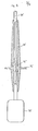
- Fig. 4 shows a paddle or spoon-shaped electrode which can be applied directly to the heart muscle.
- This electrode has an application electrode 30 in the form of a spoon or paddle, which is attached to the heart muscle for internal use during defibrillation.
- a circumferential protective electrode 32 is provided, which has a bushing 35 for the supply line.
- both the supply line for the application electrode 30 and the line connected to the protective electrode 32 are at the front. term operating handle 31 led away.
- These lines can be connected in the same manner as is shown in the exemplary embodiments in FIGS. 1 to 3.
- FIG. 5 shows an exemplary embodiment for an energy store 1 and a work switch 6 of the defibrillator circuit 37.
- the energy store 1 consists of several capacitors C ... C connected in series.
- the work switch 6 has several even-1 n if switches Sb ... Sb connected in series, 1 n the connection points of two capacitors C1 and C2 ... C n -1 and C n with the connection points of two switches Sb and Sb. ..Sb - 1 and Sb connected 1 2 nn are connected via further switches Sa 1 ... Sa n .
- the capacitors connected in series are all charged to the same voltage level.
- the capacitors are discharged one after the other in precisely defined time periods.
- the switches Sb ... Sb are closed in succession in these defined time periods.
- the respective switch Sa ... Sa via which the previous discharge of a respective capacitor was carried out, is opened.
- the capacitor C is first discharged via the closed switch Sa and the closed switch 1 Sb.
- the switches Sb ... Sb are open.
- To discharge the capacitor C the switch Sb is closed and the switch Sa is opened.
- Switch 1 Sb remains closed.
- Switch Sa is also closed. This means that the capacitor C 2 is discharged via the switch Sa, Sb, Sb.
- the remaining capacitors C ... C are discharged in the same way.
- the switches Sb ... Sb are open before the capacitor 3 n gates begin to discharge. 1 n
- the switches Sa ... Sa can be closed. 1 n
- the energy store consists of connected in parallel Capacitors C ... C.
- the capacitors 1 n are charged via a charging line 33 with switches 1 n SL ... SL connected in series with the capacitors C ... C.
- the discharge takes place via a discharge line 34, the switches SL ... SL open and the 1 n switches SE ... SE, which are in series with the capacitors C ... C, in succession at certain times stands will be closed.
- an individually desired discharge curve is formed by successively increasing the individual capacitor voltages with simultaneous discharge via the shock electrodes.
- the switches SE ... SE assume the function of the working switch 6. Diodes, transistors, thyristo-1 are also suitable for the switches SL ... SL and 1 n SE ... SE n ren and the like
Abstract
Description
Die Erfindung betrifft eine elektrische Schockelektrodenschaltung für einen Defibrillator mit einem Bedienungshandgriff und einer Anwendungselektrode, der über eine Entladungsleitung die Energie eines Energiespeichers (Kondensator) der Defibrillatorschaltung zugeführt wird.The invention relates to an electrical shock electrode circuit for a defibrillator with an operating handle and an application electrode, to which the energy of an energy store (capacitor) is supplied to the defibrillator circuit via a discharge line.
Im Energiespeicher der Defibrillatorschaltung lassen sich abgestufte Energiemengen abspeichern und entsprechend abgestufte Energiemengen (Energiedosierung) in Abhängigkeit vom Patienten und der gewünschten Behandlungsart abgeben. Die abgegebenen Energiemengen für externe Defibrillation können zwischen 20 und 320 Joule liegen.Graduated amounts of energy can be stored in the energy store of the defibrillator circuit and correspondingly graduated amounts of energy (energy dosage) can be delivered depending on the patient and the desired type of treatment. The amount of energy delivered for external defibrillation can be between 20 and 320 joules.
Defibrillatorgeräte sollen leicht transportabel sein, und es wird daher eine offene Bauweise bevorzugt. Bei dieser Bauweise sind die Defibrillatorelektroden gegen Nässe und Verschmutzung von außen ungeschützt. Ferner wird zur Kontaktierung der Anwendungselektroden häufig ein leitendes Gel verwendet, das auf die Elektrodenoberfläche aufgestriciien wird. Die Gefahr der Bildung elektrischer Kriechwege zwischen der Anwendungselektrode und dem Handgriff erhöht sich hierdurch.Defibrillator devices are said to be easily portable, and an open design is therefore preferred. With this design, the defibrillator electrodes are unprotected against moisture and dirt from the outside. Furthermore, a conductive gel is often used to make contact with the application electrodes and is applied to the electrode surface. The danger of the formation of electrical leakage paths this increases between the application electrode and the handle.
Aufgabe der Erfindung ist es daher, eine elektrische Schockelektrodenschaltung für einen Defibrillator zu schaffen, durch die ein optimaler Berührungsschutz an den Schockelektroden erzielt wird.The object of the invention is therefore to provide an electrical shock electrode circuit for a defibrillator, by means of which an optimal protection against contact with the shock electrodes is achieved.
Diese Aufgabe wird erfindungsgemäß bei der elektrischen Schockelektrodenschaltung der eingangs genannten Art dadurch gelöst, daß zwischen der Anwendungselektrode und dem Bedienungshandgriff der Schockelektrode eine ring-oder scheibenförmige Schutzelektrode vorgesehen ist, die nit der Schutzelektrode der anderen Schockelektrode elektrisch leitend verbunden ist.This object is achieved in the electrical shock electrode circuit of the type mentioned in that an annular or disk-shaped protective electrode is provided between the application electrode and the operating handle of the shock electrode, which is electrically conductively connected to the protective electrode of the other shock electrode.
Die beiden Schutzelektroden können über eine Steuerleitung niteinander verbunden sein, wobei in diese Steuerleitung Schalter eingebaut sind.The two protective electrodes can be connected to one another via a control line, switches being built into this control line.
Für das Anlegen an einen Herzmuskel können die Schockelektroden paddel- oder löffelförmig ausgebildet sein.The shock electrodes can be paddle-shaped or spoon-shaped for application to a heart muscle.
Die elektrische Schockelektrodenschaltung kann bevorzugt Anwendung finden bei einem Defibrillator, dessen schaltung in der DE-OS 32 29 134 beschrieben ist.The electrical shock electrode circuit can preferably be used in a defibrillator whose circuit is described in DE-OS 32 29 134.
Durch die Erfindung wird wegen des optimalen Berührungsschutzes an den Defibrillatorelektroden eine einwandfreie Handhabung unter Berücksichtigung wichtiger Sicherheitsfunktionen gewährleistet.Due to the optimal protection against accidental contact on the defibrillator electrodes, the invention ensures faultless handling, taking into account important safety functions.
Anhand der beiliegenden Figuren, die Ausführungsbeispiele der Erfindung darstellen, wird die Erfindung noch näher erläutert. Es zeigen:
- Fig. 1 bis 4 Ausführungsformen von Defibrillatorelektroden und
- Fig. 5 und 6 Ausführungsformen für den im Defibrillator verwendeten Energiespeicher.
- 1 to 4 embodiments of defibrillator electrodes and
- 5 and 6 embodiments for the energy storage used in the defibrillator.
Eine in den Figuren 1 bis 3 gezeigte elektrische Schaltung 37 dient zur Erzeugung von Energieirnpulsen an zwei Schockelektroden 3, 4 eines Defibrillators (wie er z. B. in der DE-OS 32 29 134 beschrieben ist), mit einem Energiespeicher (z. B. wie in Fig. 6 und 7), dessen Energie über einen geschlossenen Arbeitsschalter an die Schockelektroden 3, 4 bei Schockbehandlung eines Patienten impulsartig abgeführt wird.An
Diese Schockelektroden 3 und 4 besitzen einen Handgriff 31 und eine Anwendungselektrode 30, über die die Energie des Energiespeichers 1 bei der Defibrillation abgegeben wird. Zwischen dem Bedienungshandgriff 31 und der Anwendungselektrode 30 befindet sich eine Schutzelektrode 32, welche scheiben- oder ringförmig ausgebildet sein kann und die zumindest eine um die äußere Umfangsfläche der Defibrillationselektrode umlaufende Fläche besitzt. Bei den dargestellten Ausführungsbeispielen steht die Schutzelektrode 32 über die äußere Umfangsfläche mit einem umlaufenden Randteil über. Die Versorgungsleitung für die Anwendungselektroden 30 ist durch eine Durchführung 35 in der Schutzelektrode 32 hindurchgeführt. Wie aus den Figuren zu ersehen ist, sind die Schutzelektroden 32 der beiden Defibrillatorelektroden über eine Leitung 36 miteinander verbunden. Diese Leitung 36 kann über das Defibrillatorgerät 37 führen. Zur Überwachung der elektrisch leitenden Verbindung zwischen den beiden Schutzelektroden 32 kann die Verbindung über z. B. eine Steuerleitung erfolgen. Hierzu können, wie in der Fig. 2 dargestellt ist, zusätzliche Schalter SUI und S02 vorgesehen sein. Beim Ausfühfungsbeispiel der Fig. 3 erfolgt die Überwachung der Verbindung der beiden Schutzelektroden 32 über einen Koppler 38 und zwei Drahtleitungen.These shock electrodes 3 and 4 have a
Die spezielle Ausbildung der Defibrillatorelektroden mit Schutzelektroden 32 dient zur Vermeidung der Gefahr von elektrischen Schlägen für die Bedienungsperson aufgrund leitender Oberflächenverschmutzung der Defibrillatorelektroden. Defibriilatorgeräte sollen leicht transportabel sein, une es wird daher eine offene Bauweise bevorzugt. Bei dieser Bauweise sind die Defibrillatorelektroden gegen Nässe und Verschmutzung von außen nicht geschützt. Ferner wird zur Kontaktierung der Anwendungselektroden häufig ein leitendes Gel verwendet, das auf die Elektrodenoberfläche aufgestrichen wird. Auch hierdurch wird die Gefahr der Bildung elektrischer Kriechwege zwischen der Anwendungselektrode 30 und dem Handgriff 31 erhöht. Um nun die Bedienungsperson absolut vor solchen Kriechströmen zu schützen, wird die Schutzelektrode 32 zwischen dem Handgriff 31 und der Anwendungselektrode 30 vorgesehen.The special design of the defibrillator electrodes with
Wie aus den Figuren 1 bis 3 zu ersehen ist, können die Zuleitungen für die Anwendungselektrode 30 und die Schutzelektrode 32 in gemeinsamen Kabeln 39 untergebracht sein.As can be seen from FIGS. 1 to 3, the feed lines for the
Die Fig. 4 zeigt eine paddel- oder löffelförmige Elektrode, welche direkt an den Herzmuskel angelegt werden kann. Diese Elektrode besitzt eine Anwendungselektrode 30 in Löffel- bzw. Paddelform, welche zur internen Anwendung bei der Defibrillation an den Herzmuskel angesetzt wird. Im stielartigen Bedienungshandgriff 31 ist eine umlaufende Schutzelektrode 32 vorgesehen, die für die Versorgungsleitung eine Durchführung 35 aufweist. In einem gemeinsamen Kabel 39 werden sowohl die Versorgungsleitung für die Anwendungselektrode 30 als auch die mit der Schutzelektrode 32 verbundene Leitung vorn stielar-. tigen Bedienungshandgriff 31 weggeführt. Die Verschaltung dieser Leitungen kann in der gleichen Weise erfolgen wie bei den Ausführungsbeispielen der Figuren 1 bis 3 gezeigt ist.Fig. 4 shows a paddle or spoon-shaped electrode which can be applied directly to the heart muscle. This electrode has an
In der Fig. 5 ist ein Ausführungsbeispiel für einen Energiespeicicher 1 und einen Arbeitsschalter 6 der Defibrillatorschaltung 37 dargestellt. Der Energiespeicher 1 besteht aus mehreren in Reihe geschalteten Kondensatoren C ...C . Der Arbeitsschalter 6 besitzt mehrere eben-1 n falls in Reihe geschaltete Schalter Sb ...Sb , wobei 1 n die Verbindungspunkte jeweils zweier Kondensatoren C1 und C2...Cn -1 und Cn mit den Verbindungspunkten zweier Schalter Sb und Sb ...Sb - 1 und Sb verbunden 1 2 n n sind über weitere Schalter Sa1 ...San . FIG. 5 shows an exemplary embodiment for an
Die in Reihe geschalteten Kondensatoren werden alle auf gleichen Spannungspegel geladen. Das Entladen der Kondensatoren erfolgt nacheinander in genau festgelegten Zeitabschnitten. Hierzu werden nacheinander in diesen festgelegten Zeitabschnitten die Schalter Sb ...Sb geschlos-1 n sen. Der jeweilige Schalter Sa ...Sa , über welchen 1 n die vorhergehende Entladung eines jeweiligen Kondensators erfolgte, wird dabei geöffnet. Bei Beginn der Entladung wird zunächst der Nondensator C entladen über den ge- schlossenen Schalter Sa und den geschlossenen Schalter 1 Sb . Die Schalter Sb ...Sb sind geöffnet. Zur Ent-1 2 n ladung des Kondensators C wird der Schalter Sb ge-2 2 schlossen und der Schalter Sa geöffnet. Der Schalter 1 Sb bleibt geschlossen. Auch der Schalter Sa ist ge-1 2 schlossen. Das heißt, die Entladung des Kondensators C 2 erfolgt über den Schalter Sa , Sb , Sb . In der 2 2 1 gleichen Weise erfolgt die Entladung der restlichen Kondensatoren C ...C . Bevor die Entladung der Kondensa-3 n toren beginnt, sind die Schalter Sb ...Sb geöffnet. 1 n Die Schalter Sa ...Sa können geschlossen sein. 1 nThe capacitors connected in series are all charged to the same voltage level. The capacitors are discharged one after the other in precisely defined time periods. For this purpose, the switches Sb ... Sb are closed in succession in these defined time periods. The respective switch Sa ... Sa, via which the previous discharge of a respective capacitor was carried out, is opened. At the start of the discharge, the capacitor C is first discharged via the closed switch Sa and the closed
Durch dieses zeitliche nacheinanderfolgende Aufstocken der einzelnen Kondensatorspannungen bei gleichzeitiger Entladung über die Schockelektroden läßt sich eine individuell formbare Entladekurve erzeugen.This successive increase in time of the individual capacitor voltages with simultaneous discharge via the shock electrodes enables an individually formable discharge curve to be generated.
Für die Schalter Sa ...Sa und Sb ...Sb können 1 n 1 n Dioden, Transistoren, Thyristoren und dgl. verwendet werden.1 n 1 n diodes, transistors, thyristors and the like can be used for the switches Sa ... Sa and Sb ... Sb.
In der Fig. 6 ist ein weiteres Ausführungsbeispiel für den Energiespeicher 1 dargestellt. bei diesem Ausführungsbei- spiel besteht der Energiespeicher aus parallel geschalteten Kondensatoren C ...C . Die Aufladung der Kondensatoren 1 n erfolgt über eine Ladeleitung 33 bei mit den Kondensatoren C ...C jeweils in Reihe geschalteten Schaltern 1 n SL ...SL . Die Entladung erfolgt über eine Entladelei-1 n tung 34, wobei die Schalter SL ...SL geöffnet und die 1 n zu den Kondensatoren C ...C jeweils in Reihe liegenden 1 n Schalter SE ...SE nacheinander in bestimmten Zeitabi n ständen geschlossen werden. Auch hier erfolgt durch das zeitlich nacheinanderfolgende Aufstocken der einzelnen Kondensatorspannungen bei gleichzeitiger Entladung über die Schockelektroden die Bildung einer individuell erwünschten Entladekurve. Beim Ausführungsbeispiel der Fig. 6 übernehmen die Schalter SE ...SE die Funktion des Arbeits-1 n schalters 6. Auch für die Schalter SL ...SL und 1 n SE ...SE eignen sich Dioden, Transistoren, Thyristo-1 n ren und dgl.6 shows a further exemplary embodiment for the
Claims (7)
daß zwischen der Anwendungselektrode (30, 30 ) und dem Bedienungshandgriff (31, 31 der Schockelektrode (3 bzw. 4) eine ring- oder scheibenförmige Schutzelektrode (32) vorgesehen ist, die mit der Schutzelektrode (32, 32) der anderen Schockelektrode (4 bzw. 3) elektrisch leitend (Leitung 36) verbunden ist.1. Electrical shock electrode circuit for a defibrillator with an operating handle (31, 31) and an application electrode (30, 30), which is supplied with energy from an energy store (1) of the defibrillator circuit (37) via a discharge line (341), characterized in that
that between the application electrode (30, 30) and the operating handle (31, 31 of the shock electrode (3 or 4) an annular or disc-shaped protective electrode (32) is provided which is connected to the protective electrode (32, 32) of the other shock electrode (4th or 3) is electrically conductively connected (line 36).
daß die beiden Schutzelektroden (32) über eine Steuerleitung miteinander verbunden sind.2. Shock electrode circuit according to claim 1, characterized in
that the two protective electrodes (32) are connected to one another via a control line.
daß der Energiespeicher (1) aus in Reihe oder parallel geschalteten Kondensatoren C1, C2...Cn besteht, die aln le auf gleichen Spannungspegel geladen sind und nacheinander mittels Scnaltern SA1 ...SAn und SB1 ...SBn in bestimmten Zeitabschnitten entladen werden.3. shock electrode circuit according to claim 1 or 2, characterized by,
that the energy store (1) consists of capacitors C1, C2 ... C n connected in series or in parallel, which are charged to the same voltage level and successively by means of scanners SA 1 ... SA n and SB 1 ... SB n be unloaded at certain intervals.
daß die Schockelektroden (3, 4) paddel- oder löffelförmig ausgebildet sind.4. shock electrode circuit according to one of claims 1 to 3, characterized in
that the shock electrodes (3, 4) are paddle or spoon-shaped.
daß die Schutzelektrode (32, 32 ) zumindest eine um die äußere Umfangsfläche der Schockelektrode (3 bzw. 4) umlaufende Fläche besitzt.5. Shock electrode circuit according to one of claims 1 to 4, characterized in
that the protective electrode (32, 32) has at least one surface surrounding the outer peripheral surface of the shock electrode (3 or 4).
daß die Schutzelektrode (32, 32 ) mit einem umlaufenden Randteil über die äußere Umfangsfläche der Schockelektrode (3 bzw. 4) übersteht.6. Shock electrode circuit according to one of claims 1 to 5, characterized in
that the protective electrode (32, 32) with a peripheral edge part protrudes over the outer peripheral surface of the shock electrode (3 and 4).
daß in die Steuerleitungen Schalter SO , SO geschal-1 2 tet sind.7. shock electrode circuit according to claim 2, characterized in
that in the control lines switches SO, SO are switched-1 2 tet.
Priority Applications (1)
| Application Number | Priority Date | Filing Date | Title |
|---|---|---|---|
| AT84109215T ATE34304T1 (en) | 1983-08-03 | 1984-08-03 | ELECTRIC SHOCK ELECTRODE CIRCUIT FOR A DEFIBRILLATOR. |
Applications Claiming Priority (2)
| Application Number | Priority Date | Filing Date | Title |
|---|---|---|---|
| US51984383A | 1983-08-03 | 1983-08-03 | |
| US519843 | 1983-08-03 |
Publications (2)
| Publication Number | Publication Date |
|---|---|
| EP0135735A1 true EP0135735A1 (en) | 1985-04-03 |
| EP0135735B1 EP0135735B1 (en) | 1988-05-18 |
Family
ID=24070030
Family Applications (1)
| Application Number | Title | Priority Date | Filing Date |
|---|---|---|---|
| EP84109215A Expired EP0135735B1 (en) | 1983-08-03 | 1984-08-03 | Electric shock electrode circuit for a defibrillator |
Country Status (3)
| Country | Link |
|---|---|
| EP (1) | EP0135735B1 (en) |
| AT (1) | ATE34304T1 (en) |
| DE (1) | DE3471258D1 (en) |
Cited By (4)
| Publication number | Priority date | Publication date | Assignee | Title |
|---|---|---|---|---|
| EP0445800A1 (en) * | 1990-03-07 | 1991-09-11 | Müller, Gerhard | Electric circuit for providing a high tension impulse, particularly for a defibrillator |
| AU621839B2 (en) * | 1988-04-11 | 1992-03-26 | Fukuda Denshi Co., Ltd. | Electrode for use with a defibrillator |
| EP0691870A1 (en) * | 1993-03-31 | 1996-01-17 | Survivalink Corporation | Current leakage prevention mechanism for a defibrillator |
| EP3772361A1 (en) * | 2019-08-06 | 2021-02-10 | BIOTRONIK SE & Co. KG | Implantable pulse generator with rectangular shock shape |
Families Citing this family (1)
| Publication number | Priority date | Publication date | Assignee | Title |
|---|---|---|---|---|
| DE4110402A1 (en) * | 1991-03-28 | 1992-10-01 | Siemens Ag | DEFIBRILLATOR / CONVERTER |
Citations (5)
| Publication number | Priority date | Publication date | Assignee | Title |
|---|---|---|---|---|
| US3196877A (en) * | 1962-11-14 | 1965-07-27 | Corbin Farnsworth Inc | Defibrillation electrode device |
| US3389703A (en) * | 1966-02-03 | 1968-06-25 | Zenith Radio Corp | Defibrillator electrode or the like |
| GB1298189A (en) * | 1970-02-09 | 1972-11-29 | Medtronic Inc | Electromedical apparatus |
| US3942533A (en) * | 1974-10-17 | 1976-03-09 | Cannon Robert L Iii | Cardiac defibrillator depolarizing paddle arrangement |
| DE2811325A1 (en) * | 1978-03-16 | 1979-09-27 | Messerschmitt Boelkow Blohm | Oscillator circuit for heart surgery fibrillator - has battery powered symmetrical double transistor arrangement producing AF oscillations |
-
1984
- 1984-08-03 EP EP84109215A patent/EP0135735B1/en not_active Expired
- 1984-08-03 DE DE8484109215T patent/DE3471258D1/en not_active Expired
- 1984-08-03 AT AT84109215T patent/ATE34304T1/en not_active IP Right Cessation
Patent Citations (5)
| Publication number | Priority date | Publication date | Assignee | Title |
|---|---|---|---|---|
| US3196877A (en) * | 1962-11-14 | 1965-07-27 | Corbin Farnsworth Inc | Defibrillation electrode device |
| US3389703A (en) * | 1966-02-03 | 1968-06-25 | Zenith Radio Corp | Defibrillator electrode or the like |
| GB1298189A (en) * | 1970-02-09 | 1972-11-29 | Medtronic Inc | Electromedical apparatus |
| US3942533A (en) * | 1974-10-17 | 1976-03-09 | Cannon Robert L Iii | Cardiac defibrillator depolarizing paddle arrangement |
| DE2811325A1 (en) * | 1978-03-16 | 1979-09-27 | Messerschmitt Boelkow Blohm | Oscillator circuit for heart surgery fibrillator - has battery powered symmetrical double transistor arrangement producing AF oscillations |
Cited By (6)
| Publication number | Priority date | Publication date | Assignee | Title |
|---|---|---|---|---|
| AU621839B2 (en) * | 1988-04-11 | 1992-03-26 | Fukuda Denshi Co., Ltd. | Electrode for use with a defibrillator |
| EP0445800A1 (en) * | 1990-03-07 | 1991-09-11 | Müller, Gerhard | Electric circuit for providing a high tension impulse, particularly for a defibrillator |
| EP0691870A1 (en) * | 1993-03-31 | 1996-01-17 | Survivalink Corporation | Current leakage prevention mechanism for a defibrillator |
| EP0691870A4 (en) * | 1993-03-31 | 1996-06-05 | Survivalink Corp | Current leakage prevention mechanism for a defibrillator |
| EP3772361A1 (en) * | 2019-08-06 | 2021-02-10 | BIOTRONIK SE & Co. KG | Implantable pulse generator with rectangular shock shape |
| WO2021023506A1 (en) * | 2019-08-06 | 2021-02-11 | Biotronik Se & Co. Kg | Implantable pulse generator having rectangular shock waveform |
Also Published As
| Publication number | Publication date |
|---|---|
| EP0135735B1 (en) | 1988-05-18 |
| DE3471258D1 (en) | 1988-06-23 |
| ATE34304T1 (en) | 1988-06-15 |
Similar Documents
| Publication | Publication Date | Title |
|---|---|---|
| EP0569609B1 (en) | Implantable defibrillator system | |
| DE69825568T2 (en) | EXTERNAL H-BRIDGE DEFIBRILLATOR FOR GENERATING A TWO-PHASE WAVEFORM FOR HIGH ENERGY | |
| EP1062969B1 (en) | Electrode assembly | |
| DE69323138T3 (en) | Apparatus for delivering cardiac defibrillation sequences from pacing pulses and defibrillation shocks | |
| DD148845A5 (en) | BATTERY UNIT WITH DC TO DC CONVERTER | |
| DE718637C (en) | Device for coil field treatment with short-wave electrical oscillations | |
| DE2811325C2 (en) | Cardiac surgery fibrillator | |
| EP0445800A1 (en) | Electric circuit for providing a high tension impulse, particularly for a defibrillator | |
| DE2651031A1 (en) | MEDICAL DEVICE FOR ELECTRIC SHOCK TREATMENT | |
| EP0135735B1 (en) | Electric shock electrode circuit for a defibrillator | |
| EP0016850B1 (en) | Surge voltage diverter to protect several conductors simultaneously | |
| DE1963671A1 (en) | Ignition device used to operate an internal combustion engine | |
| DE1463662A1 (en) | Electrical power supply | |
| DE2444893A1 (en) | CIRCUIT ARRANGEMENT FOR IGNITING AT LEAST ONE GAS DISCHARGE FLASHING LAMP | |
| DE1803212C3 (en) | Circuit arrangement for an electrical machine operating alternatively as a motor or generator | |
| EP3772361A1 (en) | Implantable pulse generator with rectangular shock shape | |
| DE2646277A1 (en) | CIRCUIT ARRANGEMENT FOR CONTROLLING THE CONTINUITY OF ELECTRICAL SIGNALS | |
| EP0071965B2 (en) | Implantable heart pacemaker (ensuring a minimal amplitude) | |
| CH661383A5 (en) | THYRISTOR DEVICE. | |
| DE3910741A1 (en) | High-voltage relay circuit | |
| DD147317A1 (en) | DEVICE FOR ELECTRIC STIMULATION OF THE HEART | |
| DE3109489A1 (en) | DEFIBRILLATOR | |
| EP0269846A1 (en) | Stimulator | |
| DE2338540A1 (en) | PULSE GENERATOR USED IN A PACEMAKER THAT GENERATES PULSES WITH CONSTANT ENERGY | |
| DE2649474A1 (en) | Electrical stimulation of nerves or muscles - uses generator with cyclic discharge of coupling capacitor in intervals between pulses |
Legal Events
| Date | Code | Title | Description |
|---|---|---|---|
| PUAI | Public reference made under article 153(3) epc to a published international application that has entered the european phase |
Free format text: ORIGINAL CODE: 0009012 |
|
| AK | Designated contracting states |
Designated state(s): AT CH DE FR GB IT LI |
|
| 17P | Request for examination filed |
Effective date: 19850906 |
|
| 17Q | First examination report despatched |
Effective date: 19870415 |
|
| GRAA | (expected) grant |
Free format text: ORIGINAL CODE: 0009210 |
|
| AK | Designated contracting states |
Kind code of ref document: B1 Designated state(s): AT CH DE FR GB IT LI |
|
| REF | Corresponds to: |
Ref document number: 34304 Country of ref document: AT Date of ref document: 19880615 Kind code of ref document: T |
|
| REF | Corresponds to: |
Ref document number: 3471258 Country of ref document: DE Date of ref document: 19880623 |
|
| ET | Fr: translation filed | ||
| GBT | Gb: translation of ep patent filed (gb section 77(6)(a)/1977) | ||
| ITF | It: translation for a ep patent filed |
Owner name: BUGNION S.P.A. |
|
| PLBE | No opposition filed within time limit |
Free format text: ORIGINAL CODE: 0009261 |
|
| STAA | Information on the status of an ep patent application or granted ep patent |
Free format text: STATUS: NO OPPOSITION FILED WITHIN TIME LIMIT |
|
| 26N | No opposition filed | ||
| ITTA | It: last paid annual fee | ||
| PGFP | Annual fee paid to national office [announced via postgrant information from national office to epo] |
Ref country code: GB Payment date: 19940802 Year of fee payment: 11 |
|
| PGFP | Annual fee paid to national office [announced via postgrant information from national office to epo] |
Ref country code: FR Payment date: 19940812 Year of fee payment: 11 |
|
| PGFP | Annual fee paid to national office [announced via postgrant information from national office to epo] |
Ref country code: AT Payment date: 19940831 Year of fee payment: 11 |
|
| PGFP | Annual fee paid to national office [announced via postgrant information from national office to epo] |
Ref country code: CH Payment date: 19941129 Year of fee payment: 11 |
|
| PG25 | Lapsed in a contracting state [announced via postgrant information from national office to epo] |
Ref country code: GB Effective date: 19950803 Ref country code: AT Effective date: 19950803 |
|
| PG25 | Lapsed in a contracting state [announced via postgrant information from national office to epo] |
Ref country code: LI Effective date: 19950831 Ref country code: CH Effective date: 19950831 |
|
| GBPC | Gb: european patent ceased through non-payment of renewal fee |
Effective date: 19950803 |
|
| REG | Reference to a national code |
Ref country code: CH Ref legal event code: PL |
|
| PG25 | Lapsed in a contracting state [announced via postgrant information from national office to epo] |
Ref country code: FR Effective date: 19960430 |
|
| REG | Reference to a national code |
Ref country code: FR Ref legal event code: ST |
|
| PGFP | Annual fee paid to national office [announced via postgrant information from national office to epo] |
Ref country code: DE Payment date: 20001031 Year of fee payment: 17 |
|
| PG25 | Lapsed in a contracting state [announced via postgrant information from national office to epo] |
Ref country code: DE Free format text: LAPSE BECAUSE OF NON-PAYMENT OF DUE FEES Effective date: 20020501 |