EP0136902A2 - Electrophotographic apparatus comprising photosensitive layer of amorphous silicon type photoconductor - Google Patents
Electrophotographic apparatus comprising photosensitive layer of amorphous silicon type photoconductor Download PDFInfo
- Publication number
- EP0136902A2 EP0136902A2 EP84306674A EP84306674A EP0136902A2 EP 0136902 A2 EP0136902 A2 EP 0136902A2 EP 84306674 A EP84306674 A EP 84306674A EP 84306674 A EP84306674 A EP 84306674A EP 0136902 A2 EP0136902 A2 EP 0136902A2
- Authority
- EP
- European Patent Office
- Prior art keywords
- photosensitive drum
- drum
- electrophotographic apparatus
- temperature
- set forth
- Prior art date
- Legal status (The legal status is an assumption and is not a legal conclusion. Google has not performed a legal analysis and makes no representation as to the accuracy of the status listed.)
- Granted
Links
Images


Classifications
-
- G—PHYSICS
- G03—PHOTOGRAPHY; CINEMATOGRAPHY; ANALOGOUS TECHNIQUES USING WAVES OTHER THAN OPTICAL WAVES; ELECTROGRAPHY; HOLOGRAPHY
- G03G—ELECTROGRAPHY; ELECTROPHOTOGRAPHY; MAGNETOGRAPHY
- G03G15/00—Apparatus for electrographic processes using a charge pattern
- G03G15/75—Details relating to xerographic drum, band or plate, e.g. replacing, testing
- G03G15/751—Details relating to xerographic drum, band or plate, e.g. replacing, testing relating to drum
-
- G—PHYSICS
- G03—PHOTOGRAPHY; CINEMATOGRAPHY; ANALOGOUS TECHNIQUES USING WAVES OTHER THAN OPTICAL WAVES; ELECTROGRAPHY; HOLOGRAPHY
- G03G—ELECTROGRAPHY; ELECTROPHOTOGRAPHY; MAGNETOGRAPHY
- G03G21/00—Arrangements not provided for by groups G03G13/00 - G03G19/00, e.g. cleaning, elimination of residual charge
- G03G21/20—Humidity or temperature control also ozone evacuation; Internal apparatus environment control
- G03G21/203—Humidity
-
- G—PHYSICS
- G03—PHOTOGRAPHY; CINEMATOGRAPHY; ANALOGOUS TECHNIQUES USING WAVES OTHER THAN OPTICAL WAVES; ELECTROGRAPHY; HOLOGRAPHY
- G03G—ELECTROGRAPHY; ELECTROPHOTOGRAPHY; MAGNETOGRAPHY
- G03G21/00—Arrangements not provided for by groups G03G13/00 - G03G19/00, e.g. cleaning, elimination of residual charge
- G03G21/20—Humidity or temperature control also ozone evacuation; Internal apparatus environment control
- G03G21/206—Conducting air through the machine, e.g. for cooling, filtering, removing gases like ozone
Definitions
- the present invention relates to an electrophotographic apparatus comprising a phototensitive layer of an amorphous silicon type photocanductor. More particularly, the present invention relates to an electrophotographic apparatus in which the problem of the flow of an image, which is inherent to the use of an amorphous silicon type photoconductor, is effectively solved.
- a layer of an amorphous silicon type photoconductor has a high surface hardness and a good sensitivity to rays having a long wavelength. Accordingly, this photoconductor layer has attracted attention as a photosensitive material for the electrophotography.
- amorphous silicon type photosensitive material ordinarily used for an electrostatic copying apparatus when an amorphous silicon type photosensitive material ordinarily used for an electrostatic copying apparatus is subjected to glow discharge, the long range order accumulated on the base is lost, and the amorphous silicon type photosensitive material is constructed by interatomic bonds of silicon where only the short range order is present and therefore, many dangling bonds are present. Since the local level density is increased by the presence of the dangling bonds, these dangling bonds are ordinarily blocked with hydrogen atoms, and they are made present in the form of amorphous silicon hydride (a-Si:H) to readily cause a doping effect with a dopant such as boron or phosphorus.
- a-Si:H amorphous silicon hydride
- a photosensitive layer of this amorphous silicon hydride is repeatedly used in a known electrophotographic process, the photosensitive layer is exposed to corona discharge at such steps as charging and transfer, and hydrogen atoms are released and dangling bonds are formed again.
- This dangling bond of silicon is attacked by ozone generated by corona discharge and a silicon- oxygen bond, such as Si-OH or Si-0-Si, which is more stable than the Si-H bond, is formed.
- this oxygen atom present on the surface of the photosensitive layer is hydrophilic, if the concentration of the silicon- oxygen bond is increased with increase of the frequency of the exposure to corona discharge, molecules of water in the atmosphere surrounding the surface of the photosensitive layer are readily absorbed in the photosensitive layer and the photosensitive material becomes sensitive to the moisture. It is considered that this is the cause of the undesirable phenomenon of the flow of an image.
- water molecule adsorbing medium the phenomenon of adsorption of water molecules in the atmosphere by the oxygen atom bonded to silicon (hereinafter referred to as "water molecule adsorbing medium"), which is considered to be the cause of the flow of an image, is substantially different from the dewing phenomenon caused when a conventional Se type photosensitive material is used. The reasons are described below.
- the dewing phenomenon is not caused during the copying operation but is caused when the copying machine is used for the first time in the morning after the copying machine has been allowed to stand still in the night. In contrast, the phenomenon of the flow of an image is caused even while the copying operation is continued.
- this phenomenon is caused by the adsorption of water mole molecules in the atmosphere in the vicinity of the surface of the photosensitive layer by the water molecule absorbing medium having Si-0 bonds generated on the surface of the photosensitive layer by exposure to corona discharge.
- This adsorption of water molecules is caused relatively to the relation between the densities of the water molecule and the water molecule adsorbing medium, even if the water vapor pressure is lower than the saturated water vapor pressure.
- the surface of the amorphous silicon type photosensitive material should be maintained at a temperature of 30 to 40°C, especially 35 to 40°C, according to the present invention.
- the surface of the photosensitive material is maintained at the above-mentioned temperature not only while the main switch of the copying machine is turned on but also while the main switch is turned off, for example, in the night.
- the above-mentioned phenomenon of adsorption of water molecules in the atmosphere by the water molecule adsorbing medium on the surface of the photosensitive layer is the adsorption-desorption phenomenon which depends on the temperature, and within the above-mentioned temperature range, the desorption state can be maintained.
- adsorption-desorption phenomenon which depends on the temperature, and within the above-mentioned temperature range, the desorption state can be maintained.
- adsorption-desorption phenomenon which depends on the temperature, and within the above-mentioned temperature range, the desorption state can be maintained.
- adsorption-desorption phenomenon which depends on the temperature, and within the above-mentioned temperature range, the desorption state can be maintained.
- adsorption-desorption phenomenon which depends on the temperature, and within the above-mentioned temperature range, the desorption state can be maintained.
- adsorption-desorption phenomenon which depends on the temperature, and within the above-mentioned temperature range, the desorption state can be maintained.
- optional means can be adopted as a mechanism for heating the surface of the photosensitive material, so far as the surface temperature is maintained within the above-mentioned range.
- a heat source is arranged in the vicinity of the surface of the photosensitive material or within the photosensitive material, or a method in which hot air is fed to the surface of the photosensitive material from a heat fixation mechanism or the like.
- Adjustment of the surface temperature of the photosensitive material may be accomplished by using a known temperature-adjusting member such as a thermostat.
- a known amorphous silicon type photoconductor layer may optionally be used in the present invention.
- amorphous silicon precipitated on a substrate by plasma decomposition of a silane gas may be used.
- This amorphous silicon may be doped with hydrogen or halogen or with an element of the group III or IV of the Periodic Table, such as boron or phosphorus.
- Typical values of the physical properties of an amorphous silicon photosensitive material are a dark conductivity not higher than 10 -12 ⁇ -1 ⁇ cm, an activating energy lower than 0.85 eV, a photoconductivity higher than 10 -7 ⁇ -1 ⁇ cm -1 and an optical band gap of 1.7 to 1.9 eV. Furthermore, the amount of the bonded hydrogen is 10 to 20 atomic %and the dielectric constant of the film is in the range of from 11.5 to 12.5.
- This amorphous silicon photoconductive layer can be positively or negatively charged according to the kind of the dopant, and the voltage applied to a corona charger is ordinarily in the range of from 5 to 8 KV.
- optional means known in the field of the electrostatic photography may be adopted as mechanism for the operations of charging, imagewise exposure, development and transfer.
- the defect inherent to the use of an amorphous silicon type photoconductive layer can be eliminated by very simple means of heating the surface of the photosensitive material without adopting troublesome means such as the surface treatment of the photosensitive material.
- the electrophotographic apparatus of the present invention may be applied to not only a copying machine but also a non-impact printer such as a CRT printer or laser printer or a laser facsimile.
- Fig. 1 The entire structure of a copying machine, to which the present invention is applied, is diagrammatically illustrated in Fig. 1.
- an amorphous silicon type photoconductor layer 2 is arranged on the surface of a metal drum 1 driven and rotated.
- a main charging corona charger 3 On the circumference of the drum l, there are arranged a main charging corona charger 3, an imagewise exposure mechanism comprising a lamp 4, an original-supporting transparent plate 5 and an optical system 6, a developing mehcanism 8 having a toner 7, a toner transfer corona charger 9, a paper-separating corona charger 10, an electricity-removing lamp 11 and a cleaning mechanism 12 in the recited order.
- the photoconductor layer 2 is charged with charges of a predetermined polarity by the corona charger 3. Then, an original 13 to be copied is illuminated by the lamp 4, and the photoconductive layer 2 is exposed to a light image of the original through the optical system 6 to form an electrostatic latent image corresponding to the image of the original.
- This electrostatic latent image is developed with the toner 7 by the development mechanism 8.
- a transfer sheet 14 is supplied so that the transfer sheet 14 falls in contact with the surface of the drum at the position of the toner transfer charger 9, and corona charging of the same polarity as that of the electrostatic latent image is performed from the back face of the transfer sheet l4 to transfer the toner image to the transfer sheet 14.
- the transfer sheet 14 having the toner image transferred thereon is electrostatically peeled from the drum by the electricity-removing action of the paper-separating corona charger 10 and is fed to a heat fixation device 14.
- This heat fixation device l5 is, for example, an oven heater having heaters 16 installed therein, and heat fixation is accomplished by heat radiation by the heaters 16.
- the photoconductor layer 2, from which the toner image has been transferred, is exposed to light in front of the electricity-removing lamp 11 to erase the residual charges, and then, the residual toner is removed by the cleaning mechanism 12.
- a heater is arranged within the photosensitive drum 1 as the heating mechanism for heating the photoconductive layer 2. This heating mechanism will now be described in detail with reference to Figs. 2 and 3.
- Both the side faces of the drum 28 (1 in Fig. 1) are closed by flanges 21 and 21' having central openings 20 and 20', and a gear portion 22 is arranged on the circumferential end edge of one flange 21 to transmit the driving power from a driving motor to the drum 28.
- the rotation shaft 23 of the drum is not caused to participate directly in rotation and driving, but a heater 24 may be arranged as the heating mechanism at the position of the shaft 23 to heat the interior of the drum 28 and maintain the photosensitive layer 2 at a predetermined temperature.
- the flanges 21 and 21' are attached to both the side faces of the drum 1 by a plurality of rod members 25 having male screws on both the ends.
- the central portions of the flanges 21 and 21' have shapes including projections 26 and 26' outwardly projected and openings 20 and 20' formed at the centers thereof.
- a gear portion 22 is arranged on the circumferential end edge of one flange 21 to transmit the driving power of a driving motor (not shown) of the copying machine to the drum 28.
- the projections 26 and 26' are fitted in bearings 27 and 27' and the drum 28 is held on a drum rcceiver (not shown).
- the gear portion 22 is engaged with a driving gear of the copying machine, so that the photosensitive drum 28 is rotatably set at the copying machine.
- a heat source for example, a rod heater 24, is inserted from one of the openings 20 and 20' and is secured by heater electrode sockets 30 and 30' attached to the copying machine so that a voltage can be applied to the heater 24 from a power source 31.
- a hollow pope 32 or the like may be laid out between both the flanges 21 and 21' so as to facilitate the insertion of the heater 24.
- a Nichrome wire insulatingly covered on a thin stainless steel plate or a so-called film heater comprising a heating member sandwiched between two insulating films may be arranged within the photosensitive drum 28.
- the film filter 41 is inserted in the drum 1 and attached to the inner face of the drum 1.
- One electrode 42 is connected to the inner face of the drum 1 as the ground while the other electrode is connected to a connector 44 of a rotary brush electrode 43 arranged on the inner face side of the drum 1 on one flange 21' (composed of an insulating material such as Duracon).
- a heater voltage is applied from an external socket 46 through a fixed axial electrode 45, the voltage can be applied to the heater through the brush electrode 43 with rotation of the drum 1.
- control of the temperature of the photosensitive layer 2 heated by the heating mechanism is performed by a temperature-adjusting mechanism 47 described below.
- a temperature sensor 33 is attached in the vicinity of the surface of the photosensitive layer, and a control portion 34 for setting a predetermined temperature on receipt of a signal of the sensor 33 turns on or off a switch 35 of a heater circuit.
- a thermistor is arranged as temperature detecting means, and the output voltage to the heater is adjusted to 24 V.
- the heater is turned on or off by controlling the base current.of a transistor Tr connected in series to heater terminals CNB-1 and CNB-2.
- Control of the base current is performed by two comparators Cl and C2.
- One comparator Cl controls the base current of the transistor Tr based on the change of the electric resistance of the thermistor caused according to the change of the surface temperature of the drum.
- the other comparator C2 has a protecting function of controlling the base current of the transistor Tr so as to turn off the heater when breaking is caused in the thermistor.
- the comparator Cl compares the standard level on the negative side with the change of the voltage caused by the change of the resistance of the thermistor connected to the thermistor terminals CNB-3 and CNB-4 on the positive side, and based on the result of the comparison of both the levels, the comparator Cl is held at a low or high level.
- the comparator Cl is held at a high level, with the result that the base current of the transistor Tr flows and the heater is kept in the "on" state.
- the resistance of the thermistor is excessively lowered and the voltage on the positive side is lower than the standard level (on the negative side), with the result that the comparator is held at a low level. Accordingly, the base current of the transistor Tr does not flow and the heater is kept in the "off" state.
- a variable resistor is connected to the standard level (the negative side) so that the standard level can be changed to adjust the temperature.
- the comparator C2 acts as a protecting circuit, and a relatively high standard level is maintained on the positive side.
- the level of the positive side of the comparator Cl is higher than the standard level and the comparator Cl is held at a high level, but the level of the negative side of the comparator C2 is higher than the standard level on the positive side and hence, the comparator C2 is held at a low level. Since the base current of the transistor Tr does not flow if one of the comparators Cl and C2 is held at a low level, the base current of the transistor Tr does not flow in this case and the heater is turned off.
- bearings 53 and 53' are fitted in openings 52 and 52 t of flanges 51 and 51', and a heater 55 is attached to the central holes of the bearings through fixing members 54 and 54'.
- the heater 55 is attached to the copying machine before the photosensitive drum 28 is set at the copying machine.
- each of the numbers of the electrode and socket of the heater may be reduced to one (56 and 57 in the drawings), and connection to the power source 31 is facilitated.
- the heat source for heating the photoconductive layer 2 is disposed independently from the heat fixation mechanism, and even in the case where the photosensitive drum 28 is stopped, the photoconductive layer 2 can be uniformly heated. Therefore, even in the state where the operation of the copying machine is stopped, that is, in the case where the copying machine is not used in the night, the surface temperature of the photoconductive layer can be maintained at a level of 30 to 40°C, especially 35 to 40°C.
- the surface temperature of the photoconductive layer 2 be maintained at a level of 30 to 40°C.
- the apparatus is kept at room temperature in the night, if the drum is heated at the start of the operation of the apparatus, the flow of an image can be prevented. In this case, however, a certain time is necessary for stabilization for elevating the surface temperature of the photoconductive layer to the above-mentioned level.
- a hollow shaft 70 is arranged to extend through the central portion of the drum 1, and hot air is supplied into this shaft 70 from the heat fixation mechanism 15 to heat the photoconductive layer 2 from the substrate side.
- one end of the hollow shaft 70 is connected to the heat fixation mechanism 15 through air feed pipes 71 and 71', and the other end of the hollow shaft 70 is connected to an exhaust fan 73 through an air supply pipe 72.
- Many small holes 74 are formed on this hollow shaft 70.
- a rubber plug 75 is arranged in the hollow portion of the shaft 70 to divide the hollow portion into two parts.
- flanges 81 and 81'- having central openings 80 and 80' are disposed on both the sides of the drum 1, and the openings 80 and 80' are formed to have shapes including projections 82 and 82' projected outwardly.
- the projections 82 and 82' are fitted in bearings 83 and 83' and the drum 1 is supported in a drum-receiving portion (not shown) of the copying machine.
- the driving power for the drum 1 is transmitted from a driving motor (not shown) through a gear 84 mounted on one flange 81 arranged on one side of the drum 1, whereby the drum 1 is rotated.
- the drum 1 has a closed structure except the openings 80 and 81'. Accordingly, outer air is prevented from flowing into the interior space of the drum 1, and heating of the photoconductive layer 2 by hot air is effectively performed. Moreover, supply of hot air from the heat fixation mechanism 15 can be accomplished very easily.
- Both the end portions of the hollow shaft 70 are connected to the inner sides of the flanges 81 and 81' so that the openings 80 and 80' of the flanges 81 and 81' are covered with both the end portions of the hollow shaft 70, and the air feed pipes 71 and 72 are directed to the interior space of the hollow shaft 70 through the openings 80 and 80'.
- the air feed pipes 71 and 72 are secured to the flanges 81 and 81' through the bearings 85 and 86. Accordingly, although the hollow shaft 70 is rotated together with the drum 1 when the drum 1 is driven and rotated, the air feed pipes 71 and 72 are kept stationary.
- the heat fixation mechanism 15 since the heat fixation mechanism 15 is used as the heat source, an independent heat source need not particularly be disposed, and hot air is not supplied to the photoconductive layer 2 from the outside but hot air is supplied to the interior of the drum to heat the photoconductive layer 2. Accordingly, heating can be performed very efficiently without any bad influence being given by air streams.
- this heating by hot air be continuously conducted, but heating may be performed intermittently, so far as the surface temperature of the photoconductive layer 2 is maintained at a level of 30 to 40°C, especially 35 to 40°C.
- Control of the surface temperature of the photoconductive layer 2 is performed by a temperature-adjusting mechanism 47'.
- This temperature-adjusting mechanism 47' is principally the same as the above-mentioned temperature-adjusting mechanism. Namely, the temperature-adjusting mechanism 47' comprises a temperature sensor 33' arranged on the surface of the photoconductive layer 2 and a controller 34'.
- the operation of the exhaust fan 73 is stopped instead of turn-off of the heater.
- the exhaust fan 73 is operated again.
- the surface temperature of the photoconductive layer is adjusted to the predetermined level.
- a hot air feed mechanism 91 comprises, for example, a fan 92 arranged to feed hot air to the surface of the photoconductive layer 2 through a passage 93. If the drum 1 is idly rotated when hot air is fed, hot air is fed to the surface of the photoconductive layer 2 by the fan 92 to effect heating of the photoconductive layer 2.
- the surface of the photoconductive layer 2 is locally exposed to a part of the passage 93 connected to a heat fixation zone A of the heat fixation mechanism 15, so that when hot air passes through this passage 93, the photoconductive layer 2 is heated.
- the position of the exposure of the photoconductive layer 2 to the passage 93 is not particularly critical but optional, so far as the position is not limited by the space in the copying machine. However, in view of the heating efficiency, it is preferred that the photoconductive layer 2 be exposed to the passage 93 in the vicinity of the,heat fixation mechanism 15.
- the wall of the passage 93 on the downstream side with respect to the rotation direction of the drum 1 be arranged to abut lightly to the surface of the photoconductive layer 2. Hot air from the heat fixation zone passes through the surface portion of the photoconductive layer 2 exposed within the passage 93 and is then discharged outside the copying machine by the fan 92.
- Control of the surface temperature of the photoconductive layer 2 is accomplished by means of a temperature control mechanism 47 similar to that adopted in the embodiment shown in Figs. 1 through 3. More specifically, when the surface temperature of the photoconductive layer 2 exceeds 40°C, the operation of the fan 92 is stopped by this control mechanism 47 to perform the temperature adjustment.
- the ceiling wall of the heat fixation mechanism 15 comprises a fixed wall 100 and a slidable wall 101, and the slidable wall 101 is set at a predetermined position by a spring'102.
- One end of the slidable wall 101 is connected to a solenoid 104 through a wire 103, and the wall 101 is slid by the operation of the solenoid 104 to form an opening 105.
- the slidable wall 101 is returned to the predetermined position by the spring 102 to shut the opening 105. Accordingly, a driving circuit is formed so that the solenoid 104 is operated synchronously with the fan 98. Accordingly, while hot air is not supplied, the heat fixation zone A is intercepted from the passage 93, and the heat loss is prevented.
- heating of the photoconductive layer 2 can also be accomplished by using a hot roller.
- the structure of the copying machine comprising this heating mechanism is illustrated in Fig. 11.
- a hot roller 111 is arranged between a cleaning mechanism 12 and a main charging corona charger 3.
- the hot roller 111 is kept in contact with the photoconductive layer 2 to effect heating of the surface of the photoconductive layer 2.
- a silicone rubber roller having a heater 102 installed therein may be used as the hot roller 111, and a temperature control mechanism (not shown) similar to that adopted in the foregoing embodiments is disposed to perform the temperature control by turning on or off the heater 102 according to the surface temperature of the photoconductive layer 2.
- the hot roller 111 be kept in the state non-contacted with the photoconductive layer 2 while the copying operation is not performed and the drum 1 is stopped. Contact or non-contact of the hot roller 111 with the photoconductive layer 2 can easily be accomplished by using such means as a cam mechanism or solenoid mechanism (not shown).
- the heating mechanism as described hereinbefore is arranged so that the surface temperature of the photoconductive layer 2 be maintained at a level of 30 to 40°C.
- an interception mechanism be disposed to intercept the transfer corona charger 9 and the paper-separating corona charger 10 from the photoconductive layer 2 after termination of the copying operation.
- This problem of the flow of an image caused by the above-mentioned ions can be solved by intercepting the corona charger 10 from the photoconductive layer 2 after termination of the copying operation.
- Interception of the corona charger 10 from the photoconductive layer 2 can be accomplished by various methods.
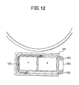
- An embodiment of this intercepting mechanism is illustrated in Fig. 12. Referring to Fig. 12, pulleys 122 are arranged around a charger unit 121 containing the charger 10 therein, and a wire 124 connected to an insulating film 123 is spread on the pulleys 122, so that the position of the insulating film 123 may be appropriately adjusted by rotating the pulleys 122. After termination of the copying operation, the pulleys 122 are rotated to cover the opening of the charger unit 121 by this intercepting film 123.
- This intercepting operation is carried out after the copying machine has been continuously used, and when the copying machine is used again, this interception is released.
- this interception may also be applied to the transfer corona charger 9.
- This transfer corona charger 9 effects charging of the same polarity as the charging polarity of the corona charger 3 for charging the photosensitive material, that is, positive charging.
- the quantities of the above-mentioned ions generated by this positive charging are small, since the transfer charger 9 is located below the photosensitive material, it is apprehended that these ions will be likely to stay in the transfer charger 9. Therefore, it is preferred that also the transfer charger 9 be intercepted from the photoconductive layer.
- the main charging corona charger 3 be intercepted from the photoconductive layer 2, though ions are hardly stored in the corona charger 3.
- an electrophotographic apparatus comprising a photosensitive layer of an amorphous silicon type photoconductor.
- the process comprising charging (positive charging), light exposure and removal of electricity (AC charging) was continuously repeated 30,000 times on a photosensitive drum of a-Si:H, whereby Si-0 bonds were formed on the surface of the drum.
- This drum was set in an ordinary copying machine, and the copying operation was continuously conducted 20 times, and then, the drum which was heated at several temperature was allowed to stand in an atmosphere maintained at a room temperature of 25°C and a relative humidity of 75 or 85°C for 10 hours at maximum.
- a film heater was uniformly bonded to the inner surface of the drum, and a heating mechanism comprising a brush electrode contacted with a sliding end terminal of the drum was arranged so that a voltage could be applied to the film heater even while the drum was rotated.
- the film heater used comprised an insulated and covered Nichrome wire arranged meanderingly at certain intervals on substantially all of one surface of a thin stainless steel substrate and a cotton cloth bonded to the surface of the Nichrome wire. After the above standing for 10 hours at maximum, the copying operation was continuously conducted at each ambient temperature of drum.
- the copying operation was continuously conducted 100 times in an atmosphere maintained at a room temperature of 25°C and a relative humidity of 75 % by using an a-Si:H drum where Si-0 bonds were formed as in Example 1 while changing the ambient temperature of the drum by using the heating mechanism shown in Figs. 2 and 3. If the ambient temperature of the drum was lower than 30°C, the flow of an image was caused when scores of prints were formed, but if the ambient temperature of the drum was at least 30°C, the flow of an image was not caused during the continuous copying operation.
- the ambient temperature of the drum exceeded 40°C, because of the inherent characteristic of the semiconductor, the dark resistivity was reduced and the image density was reduced in the prints. However, also in this case, the flow of an image was not caused.
- the relation between the ambient temperature of the drum and the image density retention ratio is shown in Fig. 13.
- the retention ratio in the drawings is a percent value calculated based on the assumption that the reflection density of the image area (solid black portion of 2 cm x 2 cm) measured by a reflection densitometer (Model TC-6D supplied by Tokyo Denshoku), which was 1.3, was 100 %.
Abstract
Description
- The present invention relates to an electrophotographic apparatus comprising a phototensitive layer of an amorphous silicon type photocanductor. More particularly, the present invention relates to an electrophotographic apparatus in which the problem of the flow of an image, which is inherent to the use of an amorphous silicon type photoconductor, is effectively solved.
- A layer of an amorphous silicon type photoconductor has a high surface hardness and a good sensitivity to rays having a long wavelength. Accordingly, this photoconductor layer has attracted attention as a photosensitive material for the electrophotography.
- However, in an electrophotographic apparatus comprising a layer of this amorphous silicon type photoconductor, when this photosensitive layer is used repeatedly, the surface of the photosensitive material becomes sensitive to the moisture and is likely to absorb water therein, with the result that the surface resistivity is reduced and surface charges migrate in the lateral direction, and the so-called flow of an image is caused.
- As means for preventing this undesirable phenomenon of the flow of an image, there has been proposed a method in which a blocking layer of a-Six.Cl-x or a-SiNx is formed on the surface of the photosensitive material. However, even if this surface treatment is performed a toner cleaning mechanism for removing the residual toner adhering to the surface of the photosensitive drum and a fixing mechanism for fixing the transferred toner image to said paper sheet, wherein a heating mechanism is arranged to heat the surface of the photosensitive drum at a temperature of 30 to 40°C.
-
- Fig. 1 is a diagram illustrating the entire structure of a copying machine to which the present invention is applied.
- Fig. 2 is a sectional view illustrating an embodiment of the present invention in which a heater is arranged as a heating mechanism in the central portion of a photosensitive drum.
- Fig. 3 is a perspective view illustrating the embodiment shown in Fig. 2.
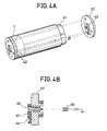
- Fig. 4-A is a perspective view showing an embodiment of the present invention in which a film heater is arranged as a heating mechanism on the inner surface of a photosensitive drum.
- Fig. 4-B is a sectional view showing the flange portion in the embodiment shown in Fig. 4-A.
- Fig. 5 is a circuit diagram illustrating an example of a temperature control circuit of a heating mechanism according to the present invention.
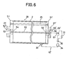
- Fig. 6 is a sectional view of a photosensitive drum, which illustrates an embodiment of attachment of a heater shown in Fig. 7.
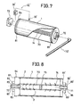
- Fig. 7 is a perspective view showing an embodiment of a heating mechanism according to the present invention.
- Fig. 8 is a sectional view of a photosensitive drum provided with the heating mechanism shown in Fig. 2.
- Fig. 9 is a diagram illustrating the entire structure of a copying machine to which another embodiment of the heating mechanism according to the present invention is applied.
- Fig. 10 is a sectional partial view illustrating the heating mechanism shown in Fig. 9.
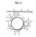
- Fig. 11 is a schematic diagram illustrating an embodiment in which a hot roller is used as a heating mechanism.
- Fig. 12 is a sectional view illustrating an intercepting mechanism for a charger unit.
- Fig. 13 is a graph illustrating the relation between the ambient temperature of a photosensitive drum and the image density retention ratio.
- As pointed out hereinbefore, when an amorphous silicon type photoconductor layer is used repeatedly, the surface of the photosensitive material becomes sensitive to the moisture and is likely to adsorb water therein, with the result that the surface charges leak in the lateral direction to render formation of an electrostatic latent image impossible and the flow of an image is caused. We made research on this undesirable phenomenon of the flow of an image, and we presumed that when the amorphous silicon photoconductive layer is used repeatedly, the flow of an image would be caused by a change of the intermolecular bond of silicon, which is caused by the exposure of the surface of the amorphous silicon photoconductive layer to the corona discharge.
- More specifically, when an amorphous silicon type photosensitive material ordinarily used for an electrostatic copying apparatus is subjected to glow discharge, the long range order accumulated on the base is lost, and the amorphous silicon type photosensitive material is constructed by interatomic bonds of silicon where only the short range order is present and therefore, many dangling bonds are present. Since the local level density is increased by the presence of the dangling bonds, these dangling bonds are ordinarily blocked with hydrogen atoms, and they are made present in the form of amorphous silicon hydride (a-Si:H) to readily cause a doping effect with a dopant such as boron or phosphorus.
- As a photosensitive layer of this amorphous silicon hydride is repeatedly used in a known electrophotographic process, the photosensitive layer is exposed to corona discharge at such steps as charging and transfer, and hydrogen atoms are released and dangling bonds are formed again. This dangling bond of silicon is attacked by ozone generated by corona discharge and a silicon- oxygen bond, such as Si-OH or Si-0-Si, which is more stable than the Si-H bond, is formed. Since this oxygen atom present on the surface of the photosensitive layer is hydrophilic, if the concentration of the silicon- oxygen bond is increased with increase of the frequency of the exposure to corona discharge, molecules of water in the atmosphere surrounding the surface of the photosensitive layer are readily absorbed in the photosensitive layer and the photosensitive material becomes sensitive to the moisture. It is considered that this is the cause of the undesirable phenomenon of the flow of an image.
- The above consideration is supported by the fact that when the surface of the photosensitive layer where the flow of an image takes place is analyzed by XPS (X-ray photoelectron spectroscopy), the Si-0 bond is detected or if the front layer where the Si-0 bond is formed is thinly peeled from the photosensitive layer where the flow of an image takes place by plasma etching, the flow of an image is not caused any more.
- We judge that the phenomenon of adsorption of water molecules in the atmosphere by the oxygen atom bonded to silicon (hereinafter referred to as "water molecule adsorbing medium"), which is considered to be the cause of the flow of an image, is substantially different from the dewing phenomenon caused when a conventional Se type photosensitive material is used. The reasons are described below.
- When the operation of a copying machine is stopped and the copying machine is allowed to stand still, as the temperature in the machine is lowered, the temperature of the photosensitive drum having a specific heat smaller than air is lowered more rapidly than the temperature of the atmosphere surrounding the drum and therefore, the water vapor pressure in the vicinity of the surface of the photosensitive drum becomes the saturated vapor pressure and the dewing phenomenon is caused. Accordingly, occurrence of the dewing phenomenon is prevented, as disclosed in, for example, Japanese Patent Application Laid-Open Specification No. 53376/80, by a method in which a dewing-preventing heater is attached to a copying machine and the temperature is maintained at a level not causing crystallization of the Se type photosensitive material, for example, at up to 30°C, so that the temperature of the surface of the photosensitive material is not lowered to the dew point. Namely, the dewing phenomenon is not caused during the copying operation but is caused when the copying machine is used for the first time in the morning after the copying machine has been allowed to stand still in the night. In contrast, the phenomenon of the flow of an image is caused even while the copying operation is continued. As pointed out hereinbefore, this phenomenon is caused by the adsorption of water mole molecules in the atmosphere in the vicinity of the surface of the photosensitive layer by the water molecule absorbing medium having Si-0 bonds generated on the surface of the photosensitive layer by exposure to corona discharge. This adsorption of water molecules is caused relatively to the relation between the densities of the water molecule and the water molecule adsorbing medium, even if the water vapor pressure is lower than the saturated water vapor pressure.
- In order to prevent occurrence of the flow of an image, described hereinbefore, it is important that during the copying operation, especially always, the surface of the amorphous silicon type photosensitive material should be maintained at a temperature of 30 to 40°C, especially 35 to 40°C, according to the present invention. By the term "always" used herein, it is meant that the surface of the photosensitive material is maintained at the above-mentioned temperature not only while the main switch of the copying machine is turned on but also while the main switch is turned off, for example, in the night.
- The above-mentioned phenomenon of adsorption of water molecules in the atmosphere by the water molecule adsorbing medium on the surface of the photosensitive layer is the adsorption-desorption phenomenon which depends on the temperature, and within the above-mentioned temperature range, the desorption state can be maintained. At too low a temperature, adsorption of water molecules by the water molecule adsorbing medium takes place and the flow of an image is caused. On the other hand, at too high a temperature, migration of charges is generally increased and retention of the charges becomes difficult, resulting in reduction of the image density.
- In the electrophotographic apparatus of the present invention, optional means can be adopted as a mechanism for heating the surface of the photosensitive material, so far as the surface temperature is maintained within the above-mentioned range. For example, there can be adopted a method in which a heat source is arranged in the vicinity of the surface of the photosensitive material or within the photosensitive material, or a method in which hot air is fed to the surface of the photosensitive material from a heat fixation mechanism or the like.
- Adjustment of the surface temperature of the photosensitive material may be accomplished by using a known temperature-adjusting member such as a thermostat.
- A known amorphous silicon type photoconductor layer may optionally be used in the present invention. For example, amorphous silicon precipitated on a substrate by plasma decomposition of a silane gas may be used. This amorphous silicon may be doped with hydrogen or halogen or with an element of the group III or IV of the Periodic Table, such as boron or phosphorus.
- Typical values of the physical properties of an amorphous silicon photosensitive material are a dark conductivity not higher than 10-12 Ω-1·cm, an activating energy lower than 0.85 eV, a photoconductivity higher than 10-7 Ω-1 ·cm-1 and an optical band gap of 1.7 to 1.9 eV. Furthermore, the amount of the bonded hydrogen is 10 to 20 atomic %and the dielectric constant of the film is in the range of from 11.5 to 12.5.
- This amorphous silicon photoconductive layer can be positively or negatively charged according to the kind of the dopant, and the voltage applied to a corona charger is ordinarily in the range of from 5 to 8 KV.
- In the apparatus of the present invention, optional means known in the field of the electrostatic photography may be adopted as mechanism for the operations of charging, imagewise exposure, development and transfer.
- As pointed out hereinbefore, in the electrophotographic apparatus of the present invention, the defect inherent to the use of an amorphous silicon type photoconductive layer can be eliminated by very simple means of heating the surface of the photosensitive material without adopting troublesome means such as the surface treatment of the photosensitive material.
- The electrophotographic apparatus of the present invention may be applied to not only a copying machine but also a non-impact printer such as a CRT printer or laser printer or a laser facsimile.
- The entire structure of a copying machine, to which the present invention is applied, is diagrammatically illustrated in Fig. 1.
- Referring to Fig. 1, an amorphous silicon
type photoconductor layer 2 is arranged on the surface of ametal drum 1 driven and rotated. On the circumference of the drum l, there are arranged a maincharging corona charger 3, an imagewise exposure mechanism comprising a lamp 4, an original-supportingtransparent plate 5 and anoptical system 6, a developingmehcanism 8 having a toner 7, a tonertransfer corona charger 9, a paper-separatingcorona charger 10, an electricity-removinglamp 11 and acleaning mechanism 12 in the recited order. - At first, the
photoconductor layer 2 is charged with charges of a predetermined polarity by thecorona charger 3. Then, an original 13 to be copied is illuminated by the lamp 4, and thephotoconductive layer 2 is exposed to a light image of the original through theoptical system 6 to form an electrostatic latent image corresponding to the image of the original. This electrostatic latent image is developed with the toner 7 by thedevelopment mechanism 8. Atransfer sheet 14 is supplied so that thetransfer sheet 14 falls in contact with the surface of the drum at the position of thetoner transfer charger 9, and corona charging of the same polarity as that of the electrostatic latent image is performed from the back face of the transfer sheet l4 to transfer the toner image to thetransfer sheet 14. Thetransfer sheet 14 having the toner image transferred thereon is electrostatically peeled from the drum by the electricity-removing action of the paper-separatingcorona charger 10 and is fed to aheat fixation device 14. - This heat fixation device l5 is, for example, an oven
heater having heaters 16 installed therein, and heat fixation is accomplished by heat radiation by theheaters 16. - The
photoconductor layer 2, from which the toner image has been transferred, is exposed to light in front of the electricity-removinglamp 11 to erase the residual charges, and then, the residual toner is removed by thecleaning mechanism 12. - In the embodiment illustrated in Fig. 1, a heater is arranged within the
photosensitive drum 1 as the heating mechanism for heating thephotoconductive layer 2. This heating mechanism will now be described in detail with reference to Figs. 2 and 3. - Both the side faces of the drum 28 (1 in Fig. 1) are closed by
flanges 21 and 21' havingcentral openings 20 and 20', and agear portion 22 is arranged on the circumferential end edge of oneflange 21 to transmit the driving power from a driving motor to thedrum 28. The rotation shaft 23 of the drum is not caused to participate directly in rotation and driving, but aheater 24 may be arranged as the heating mechanism at the position of the shaft 23 to heat the interior of thedrum 28 and maintain thephotosensitive layer 2 at a predetermined temperature. - The
flanges 21 and 21' are attached to both the side faces of thedrum 1 by a plurality ofrod members 25 having male screws on both the ends. The central portions of theflanges 21 and 21' haveshapes including projections 26 and 26' outwardly projected andopenings 20 and 20' formed at the centers thereof. Agear portion 22 is arranged on the circumferential end edge of oneflange 21 to transmit the driving power of a driving motor (not shown) of the copying machine to thedrum 28. - When the
photosensitive drum 28 having the above-mentioned structure is attached to the copying machine, theprojections 26 and 26' are fitted inbearings 27 and 27' and thedrum 28 is held on a drum rcceiver (not shown). At this point, thegear portion 22 is engaged with a driving gear of the copying machine, so that thephotosensitive drum 28 is rotatably set at the copying machine. - Attachment of the heating mechanism will now be described. Since the above-mentioned
openings 20 and 20' are formed on thephotosensitive drum 28 set at the copying machine and the driving power is transmitted through thegear 22 of theflange 21, the axis connecting theopenings 20 and 20' to each other, that is, the rotation shaft per se, does not participate in the rotation of thedrum 28. A heat source, for example, arod heater 24, is inserted from one of theopenings 20 and 20' and is secured byheater electrode sockets 30 and 30' attached to the copying machine so that a voltage can be applied to theheater 24 from apower source 31. In this embodiment of the present invention, ahollow pope 32 or the like may be laid out between both theflanges 21 and 21' so as to facilitate the insertion of theheater 24. - Instead of the above-mentioned
heater 24, a Nichrome wire insulatingly covered on a thin stainless steel plate or a so-called film heater comprising a heating member sandwiched between two insulating films may be arranged within thephotosensitive drum 28. - This embodiment using the film heater will now be described with reference to Fig. 4-A and Fig. 4-B showing the section of the flange 2l'. The
film filter 41 is inserted in thedrum 1 and attached to the inner face of thedrum 1. Oneelectrode 42 is connected to the inner face of thedrum 1 as the ground while the other electrode is connected to aconnector 44 of arotary brush electrode 43 arranged on the inner face side of thedrum 1 on one flange 21' (composed of an insulating material such as Duracon). When a heater voltage is applied from anexternal socket 46 through a fixedaxial electrode 45, the voltage can be applied to the heater through thebrush electrode 43 with rotation of thedrum 1. - Referring to Fig. 3 again, control of the temperature of the
photosensitive layer 2 heated by the heating mechanism is performed by a temperature-adjustingmechanism 47 described below. Namely, atemperature sensor 33 is attached in the vicinity of the surface of the photosensitive layer, and acontrol portion 34 for setting a predetermined temperature on receipt of a signal of thesensor 33 turns on or off aswitch 35 of a heater circuit. - An example of this temperature control circuit will now be described with reference to Fig. 5. In this circuit, a thermistor is arranged as temperature detecting means, and the output voltage to the heater is adjusted to 24 V. In principle, the heater is turned on or off by controlling the base current.of a transistor Tr connected in series to heater terminals CNB-1 and CNB-2.
- Control of the base current is performed by two comparators Cl and C2. One comparator Cl controls the base current of the transistor Tr based on the change of the electric resistance of the thermistor caused according to the change of the surface temperature of the drum. The other comparator C2 has a protecting function of controlling the base current of the transistor Tr so as to turn off the heater when breaking is caused in the thermistor.
- The comparator Cl compares the standard level on the negative side with the change of the voltage caused by the change of the resistance of the thermistor connected to the thermistor terminals CNB-3 and CNB-4 on the positive side, and based on the result of the comparison of both the levels, the comparator Cl is held at a low or high level. In the case where the surface temperature of the drum is lowered and the resistance of the thermistor is increased, the level on the positive side is higher than the standard level on the negative side and the comparator Cl is held at a high level, with the result that the base current of the transistor Tr flows and the heater is kept in the "on" state. On the other hand, in the case where the surface temperature of the drum is higher than the predetermined level, the resistance of the thermistor is excessively lowered and the voltage on the positive side is lower than the standard level (on the negative side), with the result that the comparator is held at a low level. Accordingly, the base current of the transistor Tr does not flow and the heater is kept in the "off" state.
- In the comparator Cl, a variable resistor is connected to the standard level (the negative side) so that the standard level can be changed to adjust the temperature.
- The comparator C2 acts as a protecting circuit, and a relatively high standard level is maintained on the positive side. In the case where breaking is caused in the thermistor and detection of the temperature becomes impossible, the level of the positive side of the comparator Cl is higher than the standard level and the comparator Cl is held at a high level, but the level of the negative side of the comparator C2 is higher than the standard level on the positive side and hence, the comparator C2 is held at a low level. Since the base current of the transistor Tr does not flow if one of the comparators Cl and C2 is held at a low level, the base current of the transistor Tr does not flow in this case and the heater is turned off.
- According to another embodiment of the attachment of the heating mechanism, as shown in Fig. 6,
bearings 53 and 53' are fitted inopenings flanges 51 and 51', and aheater 55 is attached to the central holes of the bearings through fixingmembers 54 and 54'. In this embodiment, theheater 55 is attached to the copying machine before thephotosensitive drum 28 is set at the copying machine. In this embodiment, each of the numbers of the electrode and socket of the heater may be reduced to one (56 and 57 in the drawings), and connection to thepower source 31 is facilitated. - In this embodiment, the heat source for heating the
photoconductive layer 2 is disposed independently from the heat fixation mechanism, and even in the case where thephotosensitive drum 28 is stopped, thephotoconductive layer 2 can be uniformly heated. Therefore, even in the state where the operation of the copying machine is stopped, that is, in the case where the copying machine is not used in the night, the surface temperature of the photoconductive layer can be maintained at a level of 30 to 40°C, especially 35 to 40°C. - In the electrophotographic apparatus of the present invention, in order to completely prevent occurrence of the flow of an image, it is preferred that even in the state where the apparatus is not used, for example, in the night, the surface temperature of the
photoconductive layer 2 be maintained at a level of 30 to 40°C. However, even when the apparatus is kept at room temperature in the night, if the drum is heated at the start of the operation of the apparatus, the flow of an image can be prevented. In this case, however, a certain time is necessary for stabilization for elevating the surface temperature of the photoconductive layer to the above-mentioned level. - An embodiment where the photoconductive layer is heated only while the copying machine is used will now be described with reference to Fig. 7. In this embodiment, hot air is fed into the interior space of the drum from the
heat fixation mechanism 15 to heat thephotoconductive layer 2. - Referring to Figs. 7 and 8 illustrating this heating mechanism in detail, a
hollow shaft 70 is arranged to extend through the central portion of thedrum 1, and hot air is supplied into thisshaft 70 from theheat fixation mechanism 15 to heat thephotoconductive layer 2 from the substrate side. - More specifically, one end of the
hollow shaft 70 is connected to theheat fixation mechanism 15 throughair feed pipes 71 and 71', and the other end of thehollow shaft 70 is connected to anexhaust fan 73 through anair supply pipe 72. Manysmall holes 74 are formed on thishollow shaft 70. Arubber plug 75 is arranged in the hollow portion of theshaft 70 to divide the hollow portion into two parts. - When the
exhaust fan 73 is operated, hot air is introduced into thehollow shaft 70 from theheat fixation system 15 and is filled in the interior space of thedrum 1 through the small holes 74. Then, this hot air is passed through thehollow shaft 70 via thesmall holes 74 and discharged outside the copying machine by theexhaust fan 73. In this manner, thephotoconductive layer 2 is heated by hot air from theheat fixation system 15, whereby the flow of an image is prevented. - In this embodiment, in order to arrange the
hollow shaft 70 to extend through the interior of the drum,flanges 81 and 81'- havingcentral openings 80 and 80' are disposed on both the sides of thedrum 1, and theopenings 80 and 80' are formed to haveshapes including projections 82 and 82' projected outwardly. Theprojections 82 and 82' are fitted inbearings 83 and 83' and thedrum 1 is supported in a drum-receiving portion (not shown) of the copying machine. In this structure, the driving power for thedrum 1 is transmitted from a driving motor (not shown) through agear 84 mounted on oneflange 81 arranged on one side of thedrum 1, whereby thedrum 1 is rotated. - In this embodiment, as is apparent from the foregoing description, the
drum 1 has a closed structure except theopenings 80 and 81'. Accordingly, outer air is prevented from flowing into the interior space of thedrum 1, and heating of thephotoconductive layer 2 by hot air is effectively performed. Moreover, supply of hot air from theheat fixation mechanism 15 can be accomplished very easily. - Both the end portions of the
hollow shaft 70 are connected to the inner sides of theflanges 81 and 81' so that theopenings 80 and 80' of theflanges 81 and 81' are covered with both the end portions of thehollow shaft 70, and theair feed pipes hollow shaft 70 through theopenings 80 and 80'. Theair feed pipes flanges 81 and 81' through thebearings 85 and 86. Accordingly, although thehollow shaft 70 is rotated together with thedrum 1 when thedrum 1 is driven and rotated, theair feed pipes - In this embodiment, since the
heat fixation mechanism 15 is used as the heat source, an independent heat source need not particularly be disposed, and hot air is not supplied to thephotoconductive layer 2 from the outside but hot air is supplied to the interior of the drum to heat thephotoconductive layer 2. Accordingly, heating can be performed very efficiently without any bad influence being given by air streams. - It is preferred that this heating by hot air be continuously conducted, but heating may be performed intermittently, so far as the surface temperature of the
photoconductive layer 2 is maintained at a level of 30 to 40°C, especially 35 to 40°C. - Control of the surface temperature of the
photoconductive layer 2 is performed by a temperature-adjusting mechanism 47'. This temperature-adjusting mechanism 47' is principally the same as the above-mentioned temperature-adjusting mechanism. Namely, the temperature-adjusting mechanism 47' comprises a temperature sensor 33' arranged on the surface of thephotoconductive layer 2 and a controller 34'. When the surface temperature of thephotoconductive layer 2 is elevated beyond a predetermined level, the operation of theexhaust fan 73 is stopped instead of turn-off of the heater. When the surface temperature of thephotoconductive layer 2 is lowered below the predetermined level, theexhaust fan 73 is operated again. Thus, the surface temperature of the photoconductive layer is adjusted to the predetermined level. - Referring to Fig. 9 illustrating another embodiment where heating is effected while the copying machine is used and hot air is fed from the
heat fixation mechanism 15 to the surface of thephotoconductive layer 2 to heat the surface of thephotoconductive layer 2, a hotair feed mechanism 91 comprises, for example, afan 92 arranged to feed hot air to the surface of thephotoconductive layer 2 through apassage 93. If thedrum 1 is idly rotated when hot air is fed, hot air is fed to the surface of thephotoconductive layer 2 by thefan 92 to effect heating of thephotoconductive layer 2. - More specifically, in this embodiment, the surface of the
photoconductive layer 2 is locally exposed to a part of thepassage 93 connected to a heat fixation zone A of theheat fixation mechanism 15, so that when hot air passes through thispassage 93, thephotoconductive layer 2 is heated. The position of the exposure of thephotoconductive layer 2 to thepassage 93 is not particularly critical but optional, so far as the position is not limited by the space in the copying machine. However, in view of the heating efficiency, it is preferred that thephotoconductive layer 2 be exposed to thepassage 93 in the vicinity of the,heat fixation mechanism 15. In order to prevent supplied hot air from diffusing into the copying machine through this exposed portion, it is preferred that the wall of thepassage 93 on the downstream side with respect to the rotation direction of thedrum 1 be arranged to abut lightly to the surface of thephotoconductive layer 2. Hot air from the heat fixation zone passes through the surface portion of thephotoconductive layer 2 exposed within thepassage 93 and is then discharged outside the copying machine by thefan 92. - Control of the surface temperature of the
photoconductive layer 2 is accomplished by means of atemperature control mechanism 47 similar to that adopted in the embodiment shown in Figs. 1 through 3. More specifically, when the surface temperature of thephotoconductive layer 2 exceeds 40°C, the operation of thefan 92 is stopped by thiscontrol mechanism 47 to perform the temperature adjustment. - In this embodiment, in the case where the
passage 93 is always connected to the heat fixation zone A, when an oven heater is used as theheat fixation mechanism 15 as shown in Fig. 9, the ambient temperature of thefixation mechanism 15 is lowered, and hence, it is apprehended that bad influences will be imposed on the fixing operation. Accordingly, in this case, as shown in Fig. 10, a double-wall structure is given to theheat fixation mechanism 15 and one wall is slidably arranged. Namely, when hot air is fed, one wall is slid to form an opening. - In the embodiment illustrated in Fig. 10, the ceiling wall of the
heat fixation mechanism 15 comprises a fixed wall 100 and aslidable wall 101, and theslidable wall 101 is set at a predetermined position by a spring'102. One end of theslidable wall 101 is connected to asolenoid 104 through awire 103, and thewall 101 is slid by the operation of thesolenoid 104 to form anopening 105. When the operation of thesolenoid 104 is stopped, theslidable wall 101 is returned to the predetermined position by thespring 102 to shut theopening 105. Accordingly, a driving circuit is formed so that thesolenoid 104 is operated synchronously with the fan 98. Accordingly, while hot air is not supplied, the heat fixation zone A is intercepted from thepassage 93, and the heat loss is prevented. - In the present invention, heating of the
photoconductive layer 2 can also be accomplished by using a hot roller. The structure of the copying machine comprising this heating mechanism is illustrated in Fig. 11. Referring to Fig. 11, ahot roller 111 is arranged between acleaning mechanism 12 and a maincharging corona charger 3. During the copying operation, thehot roller 111 is kept in contact with thephotoconductive layer 2 to effect heating of the surface of thephotoconductive layer 2. For example, a silicone rubber roller having aheater 102 installed therein may be used as thehot roller 111, and a temperature control mechanism (not shown) similar to that adopted in the foregoing embodiments is disposed to perform the temperature control by turning on or off theheater 102 according to the surface temperature of thephotoconductive layer 2. - In order to prevent deformation of the roller surface or other trouble, it is preferred that the
hot roller 111 be kept in the state non-contacted with thephotoconductive layer 2 while the copying operation is not performed and thedrum 1 is stopped. Contact or non-contact of thehot roller 111 with thephotoconductive layer 2 can easily be accomplished by using such means as a cam mechanism or solenoid mechanism (not shown). - In the present invention, the heating mechanism as described hereinbefore is arranged so that the surface temperature of the
photoconductive layer 2 be maintained at a level of 30 to 40°C. In the present invention, it is preferred that an interception mechanism be disposed to intercept thetransfer corona charger 9 and the paper-separatingcorona charger 10 from thephotoconductive layer 2 after termination of the copying operation. - The problem of the flow of an image is substantially solved by arranging the heating mechanism described hereinbefore, However, it sometimes happens that this problem is not completely solved only by disposition of the heating mechanism. More specifically, as shown in the Examples given hereinafter, it sometimes happens that the flow is caused in a formed image, especially at the position above the paper-separating
corona charger 10. The reason has not been precisely elucidated, but it is believed that ions such as fH20)nH+, 03 and CO3 are generated in the atmosphere in thecorona charger 10 by AC charging and since thiscorona charger 10 is arranged below thephotosensitive drum 1, these ions rise from thecorona charger 10 and adhere to thephotoconductive layer 2 to cause the flow of an image. - This problem of the flow of an image caused by the above-mentioned ions can be solved by intercepting the
corona charger 10 from thephotoconductive layer 2 after termination of the copying operation. - Interception of the
corona charger 10 from thephotoconductive layer 2 can be accomplished by various methods. An embodiment of this intercepting mechanism is illustrated in Fig. 12. Referring to Fig. 12,pulleys 122 are arranged around acharger unit 121 containing thecharger 10 therein, and awire 124 connected to an insulatingfilm 123 is spread on thepulleys 122, so that the position of the insulatingfilm 123 may be appropriately adjusted by rotating thepulleys 122. After termination of the copying operation, thepulleys 122 are rotated to cover the opening of thecharger unit 121 by this interceptingfilm 123. - This intercepting operation is carried out after the copying machine has been continuously used, and when the copying machine is used again, this interception is released.
- Of course, this interception may also be applied to the
transfer corona charger 9. Thistransfer corona charger 9 effects charging of the same polarity as the charging polarity of thecorona charger 3 for charging the photosensitive material, that is, positive charging. Although the quantities of the above-mentioned ions generated by this positive charging are small, since thetransfer charger 9 is located below the photosensitive material, it is apprehended that these ions will be likely to stay in thetransfer charger 9. Therefore, it is preferred that also thetransfer charger 9 be intercepted from the photoconductive layer. - Furthermore, in order to further enhance the safety, it is preferred that also the main
charging corona charger 3 be intercepted from thephotoconductive layer 2, though ions are hardly stored in thecorona charger 3. - As is apparent from the foregoing description, according to the present invention, the problem of the flow of an image is effectively solved in an electrophotographic apparatus comprising a photosensitive layer of an amorphous silicon type photoconductor.
- The present invention will now be described with reference to the following examples.
- The process comprising charging (positive charging), light exposure and removal of electricity (AC charging) was continuously repeated 30,000 times on a photosensitive drum of a-Si:H, whereby Si-0 bonds were formed on the surface of the drum. This drum was set in an ordinary copying machine, and the copying operation was continuously conducted 20 times, and then, the drum which was heated at several temperature was allowed to stand in an atmosphere maintained at a room temperature of 25°C and a relative humidity of 75 or 85°C for 10 hours at maximum. Incidentally, as shown in Fig. 4-A and 4-B, a film heater was uniformly bonded to the inner surface of the drum, and a heating mechanism comprising a brush electrode contacted with a sliding end terminal of the drum was arranged so that a voltage could be applied to the film heater even while the drum was rotated. The film heater used comprised an insulated and covered Nichrome wire arranged meanderingly at certain intervals on substantially all of one surface of a thin stainless steel substrate and a cotton cloth bonded to the surface of the Nichrome wire. After the above standing for 10 hours at maximum, the copying operation was continuously conducted at each ambient temperature of drum.
- The relation between the ambient temperature and standing time of the drum surface and occurrence of the flow of an image at the above continuous copying operation is shown in Table 1.
-

- The copying operation was continuously conducted 100 times in an atmosphere maintained at a room temperature of 25°C and a relative humidity of 75 % by using an a-Si:H drum where Si-0 bonds were formed as in Example 1 while changing the ambient temperature of the drum by using the heating mechanism shown in Figs. 2 and 3. If the ambient temperature of the drum was lower than 30°C, the flow of an image was caused when scores of prints were formed, but if the ambient temperature of the drum was at least 30°C, the flow of an image was not caused during the continuous copying operation.
- If the ambient temperature of the drum exceeded 40°C, because of the inherent characteristic of the semiconductor, the dark resistivity was reduced and the image density was reduced in the prints. However, also in this case, the flow of an image was not caused. The relation between the ambient temperature of the drum and the image density retention ratio is shown in Fig. 13. Incidentally, the retention ratio in the drawings is a percent value calculated based on the assumption that the reflection density of the image area (solid black portion of 2 cm x 2 cm) measured by a reflection densitometer (Model TC-6D supplied by Tokyo Denshoku), which was 1.3, was 100 %.
- From the results obtained in Examples 1 and 2, it was confirmed that if the temperature of the vicinity of the surface of the photosensitive material is adjusted to 30 to 40°C, stable images having a high density can be obtained without the flow of an image, and especially, if the temperature of the vicinity of the surface of the photosensitive material is adjusted to 35 to 40°C, even under such a high humidity condition as a relative humidity of 85 %, bleeding of printed letters is not caused at all and very stable images can be obtained.
Claims (12)
Applications Claiming Priority (8)
| Application Number | Priority Date | Filing Date | Title |
|---|---|---|---|
| JP180738/83 | 1983-09-30 | ||
| JP58180738A JPS6073633A (en) | 1983-09-30 | 1983-09-30 | Improvement of electrophotographic method |
| JP20282583A JPS6095551A (en) | 1983-10-31 | 1983-10-31 | Electrophotographic method |
| JP202825/83 | 1983-10-31 | ||
| JP17369283U JPS6082657U (en) | 1983-11-11 | 1983-11-11 | Heating mechanism for photoreceptor drum in image forming apparatus |
| JP173692/83U | 1983-11-11 | ||
| JP18377083U JPS6092263U (en) | 1983-11-30 | 1983-11-30 | Heating device for photoreceptor drum in image forming apparatus |
| JP183770/83U | 1983-11-30 |
Publications (3)
| Publication Number | Publication Date |
|---|---|
| EP0136902A2 true EP0136902A2 (en) | 1985-04-10 |
| EP0136902A3 EP0136902A3 (en) | 1986-12-10 |
| EP0136902B1 EP0136902B1 (en) | 1990-01-31 |
Family
ID=27474521
Family Applications (1)
| Application Number | Title | Priority Date | Filing Date |
|---|---|---|---|
| EP84306674A Expired - Lifetime EP0136902B1 (en) | 1983-09-30 | 1984-09-28 | Electrophotographic apparatus comprising photosensitive layer of amorphous silicon type photoconductor |
Country Status (3)
| Country | Link |
|---|---|
| US (1) | US4607936A (en) |
| EP (1) | EP0136902B1 (en) |
| DE (1) | DE3481225D1 (en) |
Cited By (6)
| Publication number | Priority date | Publication date | Assignee | Title |
|---|---|---|---|---|
| DE3631495A1 (en) * | 1985-09-17 | 1987-03-26 | Canon Kk | IMAGE SUPPORT ELEMENT USED WITH AN IMAGE GENERATION DEVICE |
| US4975744A (en) * | 1985-09-17 | 1990-12-04 | Canon Kabushiki Kaisha | Image bearing member and driving mechanism therefor |
| DE4040962A1 (en) * | 1989-12-20 | 1991-06-27 | Hitachi Ltd | TRANSFER DEVICE AND ELECTROPHOTOGRAPHIC DEVICE |
| EP0676678A1 (en) * | 1994-04-04 | 1995-10-11 | Mita Industrial Co. Ltd. | Image forming apparatus |
| EP0957404A1 (en) * | 1998-05-14 | 1999-11-17 | Canon Kabushiki Kaisha | Electrophotographic, photosensitive member and image forming apparatus |
| EP0957405A1 (en) * | 1998-05-14 | 1999-11-17 | Canon Kabushiki Kaisha | Image forming apparatus |
Families Citing this family (27)
| Publication number | Priority date | Publication date | Assignee | Title |
|---|---|---|---|---|
| JPS61165764A (en) * | 1985-01-17 | 1986-07-26 | Sharp Corp | Electronic photo process |
| US5019862A (en) * | 1986-01-23 | 1991-05-28 | Sharp Kabushiki Kaisha | Heat control for photoreceptor |
| JPS63125967A (en) * | 1986-11-17 | 1988-05-30 | Canon Inc | Image exposing device for electrophotographic method |
| EP0322903B1 (en) * | 1987-12-29 | 1994-06-15 | Canon Kabushiki Kaisha | Optical image recording apparatus |
| JPH0750356B2 (en) * | 1988-09-30 | 1995-05-31 | キヤノン株式会社 | Electrophotographic device |
| US5177529A (en) * | 1988-11-25 | 1993-01-05 | Xerox Corporation | Machine with removable unit having two element electrical connection |
| JPH02251867A (en) * | 1989-03-24 | 1990-10-09 | Hitachi Koki Co Ltd | Electrophotographic copying/printing device |
| GB2232244B (en) * | 1989-05-30 | 1992-11-18 | Deutsche Forsch Luft Raumfahrt | A device for measuring the temperature of a body in a vacuum |
| US5155531A (en) * | 1989-09-29 | 1992-10-13 | Ricoh Company, Ltd. | Apparatus for decomposing ozone by using a solvent mist |
| EP0466173B1 (en) * | 1990-07-13 | 1998-10-21 | Canon Kabushiki Kaisha | Process cartridge and image forming apparatus using same |
| JP3169234B2 (en) * | 1990-10-25 | 2001-05-21 | 株式会社リコー | Image forming device |
| US5592274A (en) * | 1992-01-31 | 1997-01-07 | Fuji Xerox Co., Ltd. | Electrophotographic apparatus and process for simultaneously transferring and fixing toner image onto transfer paper |
| EP0679955B9 (en) * | 1994-04-27 | 2005-01-12 | Canon Kabushiki Kaisha | Electrophotographic light-receiving member and process for its production |
| JP3368109B2 (en) * | 1995-08-23 | 2003-01-20 | キヤノン株式会社 | Light receiving member for electrophotography |
| JP3862334B2 (en) | 1995-12-26 | 2006-12-27 | キヤノン株式会社 | Light receiving member for electrophotography |
| KR19980026295U (en) * | 1996-11-08 | 1998-08-05 | 김광호 | Uniformity of Temperature Distribution of Heat Roller for Laser Beam Printer |
| US5788382A (en) * | 1997-08-28 | 1998-08-04 | Output Technology, Inc. | Imaging drum |
| JP3976955B2 (en) | 1999-09-06 | 2007-09-19 | キヤノン株式会社 | Electrophotographic method |
| US6537714B2 (en) | 2000-07-07 | 2003-03-25 | Canon Kabushiki Kaisha | Image-forming method and image-forming apparatus |
| US6605405B2 (en) | 2000-07-26 | 2003-08-12 | Canon Kabushiki Kaisha | Electrophotographic method and electrophotographic apparatus |
| US6895209B2 (en) * | 2002-04-19 | 2005-05-17 | Ricoh Company, Ltd. | Cleaning device and image forming apparatus using the same |
| EP1870781B1 (en) * | 2006-06-21 | 2013-08-14 | Océ-Technologies B.V. | A roller for a printer and a method of cooling the roller surface |
| JP5000385B2 (en) * | 2006-06-21 | 2012-08-15 | オセ−テクノロジーズ・ベー・ヴエー | Roller for printer and method for cooling roller surface |
| JP4850619B2 (en) | 2006-08-14 | 2012-01-11 | キヤノン株式会社 | Image forming apparatus |
| JP5163086B2 (en) * | 2007-12-12 | 2013-03-13 | 富士ゼロックス株式会社 | Image forming apparatus |
| JP5534873B2 (en) * | 2010-03-09 | 2014-07-02 | キヤノン株式会社 | Image forming apparatus |
| JP5193247B2 (en) * | 2010-03-31 | 2013-05-08 | 京セラドキュメントソリューションズ株式会社 | Holder and photoconductor cooling structure and image forming apparatus provided with the same |
Citations (9)
| Publication number | Priority date | Publication date | Assignee | Title |
|---|---|---|---|---|
| DE2509860A1 (en) * | 1975-03-04 | 1976-09-16 | Xerox Corp | METHODS OF CONTROLLING PHOTORECEPTOR FATIGUE EFFECTS IN SELENIUM-ARSENE-CONTAINING XEROGRAPHIC PHOTORECEPTORS |
| JPS576844A (en) * | 1980-06-14 | 1982-01-13 | Ricoh Co Ltd | Developing apparatus |
| US4319828A (en) * | 1971-06-03 | 1982-03-16 | Canon Kabushiki Kaisha | Copying apparatus with a heated photosensitive drum |
| JPS5786877A (en) * | 1980-11-20 | 1982-05-31 | Canon Inc | Temperature controller for photoreceptor |
| JPS5823079A (en) * | 1981-08-04 | 1983-02-10 | Canon Inc | Electrophotographic photoreceptor |
| JPS5863948A (en) * | 1981-10-14 | 1983-04-16 | Konishiroku Photo Ind Co Ltd | Image formation |
| JPS5878179A (en) * | 1981-11-05 | 1983-05-11 | Ricoh Co Ltd | Constant-temperature controller of photosensitive body |
| JPS59208558A (en) * | 1983-05-12 | 1984-11-26 | Mita Ind Co Ltd | Electrophotographic method |
| US4585319A (en) * | 1982-11-29 | 1986-04-29 | Konishiroku Photo Industry Co., Ltd. | Recording apparatus for electrostatic images |
Family Cites Families (4)
| Publication number | Priority date | Publication date | Assignee | Title |
|---|---|---|---|---|
| US4161357A (en) * | 1977-09-02 | 1979-07-17 | Xerox Corporation | Photoreceptor heating apparatus |
| US4484809B1 (en) * | 1977-12-05 | 1995-04-18 | Plasma Physics Corp | Glow discharge method and apparatus and photoreceptor devices made therewith |
| US4344700A (en) * | 1978-12-08 | 1982-08-17 | Canon Kabushiki Kaisha | Mechanism for mounting and dismounting a screen-like photosensitive medium |
| US4299474A (en) * | 1979-12-26 | 1981-11-10 | International Business Machines Corporation | Component mounting apparatus useful for compact copiers |
-
1984
- 1984-09-28 US US06/655,533 patent/US4607936A/en not_active Expired - Fee Related
- 1984-09-28 EP EP84306674A patent/EP0136902B1/en not_active Expired - Lifetime
- 1984-09-28 DE DE8484306674T patent/DE3481225D1/en not_active Expired - Lifetime
Patent Citations (9)
| Publication number | Priority date | Publication date | Assignee | Title |
|---|---|---|---|---|
| US4319828A (en) * | 1971-06-03 | 1982-03-16 | Canon Kabushiki Kaisha | Copying apparatus with a heated photosensitive drum |
| DE2509860A1 (en) * | 1975-03-04 | 1976-09-16 | Xerox Corp | METHODS OF CONTROLLING PHOTORECEPTOR FATIGUE EFFECTS IN SELENIUM-ARSENE-CONTAINING XEROGRAPHIC PHOTORECEPTORS |
| JPS576844A (en) * | 1980-06-14 | 1982-01-13 | Ricoh Co Ltd | Developing apparatus |
| JPS5786877A (en) * | 1980-11-20 | 1982-05-31 | Canon Inc | Temperature controller for photoreceptor |
| JPS5823079A (en) * | 1981-08-04 | 1983-02-10 | Canon Inc | Electrophotographic photoreceptor |
| JPS5863948A (en) * | 1981-10-14 | 1983-04-16 | Konishiroku Photo Ind Co Ltd | Image formation |
| JPS5878179A (en) * | 1981-11-05 | 1983-05-11 | Ricoh Co Ltd | Constant-temperature controller of photosensitive body |
| US4585319A (en) * | 1982-11-29 | 1986-04-29 | Konishiroku Photo Industry Co., Ltd. | Recording apparatus for electrostatic images |
| JPS59208558A (en) * | 1983-05-12 | 1984-11-26 | Mita Ind Co Ltd | Electrophotographic method |
Non-Patent Citations (11)
| Title |
|---|
| IBM TECHNICAL DISCLOSURE BULLETIN, vol. 19, no. 2, July 1976, pages 392; New York, (US) R.J. CHADWELL et al.: "Control of photoconductor environment." * |
| PATENTS ABSTACTS OF JAPAN, vol. 7, no. 101, (P-194)(1246), April 28, 1983 & JP-A- 58 023 079 * |
| PATENTS ABSTACTS OF JAPAN, vol.7, no. 152, (P-208)(1297), July 5, 1983 & JP-A- 58 063 948 * |
| PATENTS ABSTRACTS OF JAPAN, vol. 6, no. 168, (P-139) (1046), September 2, 1982; & JP-A-57 06 844 (CANON K.K.) 31-05-1982 * |
| PATENTS ABSTRACTS OF JAPAN, vol. 6, no. 168, (P-139) (1046), September 2, 1982; & JP-A-57 086 877 (CANON K.K.) 31-05-1982 * |
| PATENTS ABSTRACTS OF JAPAN, vol. 7, no. 101, (P-194) (1246), April 28, 1983; & JP-A-58 023 079 (CANON K.K.) 10-02-1983 * |
| PATENTS ABSTRACTS OF JAPAN, vol. 7, no. 152, (P-208) (1297), July 5, 1983; & JP-A-58 063 948 (KONISHIROKU SHASHIN KOGYO K.K.) 16-04-1983 * |
| PATENTS ABSTRACTS OF JAPAN, vol. 7, no. 172, (P-213) (1317), July 29, 1983; & JP-A-58 078 179 (RICOH K.K.) 11-05-1983 * |
| PATENTS ABSTRACTS OF JAPAN, vol. 9, no. 79, (P-347) (1802), April 9, 1985; & JP-A-59 208 558 (MITA KOGYO K.K.) 26-11-1984 * |
| PATENTS ABSTRACTS OF JAPAN, vol.6, no. 168, (P-139)(1046), September 2, 1982 & JP-A-57 086 877 * |
| PATENTS ABSTRACTS OF JAPAN, vol.7, no. 172, (P-213)(1317), July 29, 1983 & JP-A- 58 023 079 * |
Cited By (8)
| Publication number | Priority date | Publication date | Assignee | Title |
|---|---|---|---|---|
| DE3631495A1 (en) * | 1985-09-17 | 1987-03-26 | Canon Kk | IMAGE SUPPORT ELEMENT USED WITH AN IMAGE GENERATION DEVICE |
| US4839690A (en) * | 1985-09-17 | 1989-06-13 | Canon Kabushiki Kaisha | Image bearing member usable with image forming apparatus |
| US4975744A (en) * | 1985-09-17 | 1990-12-04 | Canon Kabushiki Kaisha | Image bearing member and driving mechanism therefor |
| DE4040962A1 (en) * | 1989-12-20 | 1991-06-27 | Hitachi Ltd | TRANSFER DEVICE AND ELECTROPHOTOGRAPHIC DEVICE |
| EP0676678A1 (en) * | 1994-04-04 | 1995-10-11 | Mita Industrial Co. Ltd. | Image forming apparatus |
| EP0957404A1 (en) * | 1998-05-14 | 1999-11-17 | Canon Kabushiki Kaisha | Electrophotographic, photosensitive member and image forming apparatus |
| EP0957405A1 (en) * | 1998-05-14 | 1999-11-17 | Canon Kabushiki Kaisha | Image forming apparatus |
| US6122467A (en) * | 1998-05-14 | 2000-09-19 | Canon Kabushiki Kaisha | Image forming apparatus using an amorphous silicon photosensitive member having a thin cylinder |
Also Published As
| Publication number | Publication date |
|---|---|
| EP0136902B1 (en) | 1990-01-31 |
| US4607936A (en) | 1986-08-26 |
| EP0136902A3 (en) | 1986-12-10 |
| DE3481225D1 (en) | 1990-03-08 |
Similar Documents
| Publication | Publication Date | Title |
|---|---|---|
| US4607936A (en) | Electrophotographic apparatus comprising photosensitive layer of amorphous silicon type photoconductor | |
| JP2614865B2 (en) | Electrophotographic printing machine with simultaneous transfer and fixing device | |
| US4407580A (en) | Transfer device | |
| EP0338546B1 (en) | Charger and image forming apparatus with same | |
| US8036565B2 (en) | Image forming apparatus including a mechanism to move a discharge wire cleaning member and a shutter for a corona charger | |
| JPS6095551A (en) | Electrophotographic method | |
| US4415254A (en) | Electrophotographic copying apparatus with transfer bias voltage stabilizer | |
| JPH0134205Y2 (en) | ||
| US5055879A (en) | Apparatus for ozoneless efficient charging of a photoreceptive drum in an electrophotographic printer | |
| JPH0450591B2 (en) | ||
| JPH0134206Y2 (en) | ||
| JP2587215B2 (en) | Electrophotographic method | |
| JPH0121313Y2 (en) | ||
| JPS59208558A (en) | Electrophotographic method | |
| JPH0455309B2 (en) | ||
| JP3095505B2 (en) | Image forming device | |
| JPH11218996A (en) | Electrifying device | |
| JP3368505B2 (en) | Image forming device | |
| JP3554645B2 (en) | Image forming device | |
| JPS606841Y2 (en) | Temperature and humidity protection device | |
| JP3659458B2 (en) | Electrophotographic photoreceptor | |
| JPS59142581A (en) | Stabilizing method of electrophotographic type picture | |
| JP3736713B2 (en) | Image forming apparatus | |
| JPS60201364A (en) | Copying machine | |
| JPS6219754B2 (en) |
Legal Events
| Date | Code | Title | Description |
|---|---|---|---|
| PUAI | Public reference made under article 153(3) epc to a published international application that has entered the european phase |
Free format text: ORIGINAL CODE: 0009012 |
|
| AK | Designated contracting states |
Designated state(s): DE FR GB |
|
| PUAL | Search report despatched |
Free format text: ORIGINAL CODE: 0009013 |
|
| AK | Designated contracting states |
Kind code of ref document: A3 Designated state(s): DE FR GB |
|
| 17P | Request for examination filed |
Effective date: 19870113 |
|
| 17Q | First examination report despatched |
Effective date: 19880524 |
|
| GRAA | (expected) grant |
Free format text: ORIGINAL CODE: 0009210 |
|
| AK | Designated contracting states |
Kind code of ref document: B1 Designated state(s): DE FR GB |
|
| REF | Corresponds to: |
Ref document number: 3481225 Country of ref document: DE Date of ref document: 19900308 |
|
| ET | Fr: translation filed | ||
| PLBE | No opposition filed within time limit |
Free format text: ORIGINAL CODE: 0009261 |
|
| STAA | Information on the status of an ep patent application or granted ep patent |
Free format text: STATUS: NO OPPOSITION FILED WITHIN TIME LIMIT |
|
| 26N | No opposition filed | ||
| PGFP | Annual fee paid to national office [announced via postgrant information from national office to epo] |
Ref country code: FR Payment date: 19950911 Year of fee payment: 12 |
|
| PGFP | Annual fee paid to national office [announced via postgrant information from national office to epo] |
Ref country code: GB Payment date: 19950919 Year of fee payment: 12 |
|
| PGFP | Annual fee paid to national office [announced via postgrant information from national office to epo] |
Ref country code: DE Payment date: 19950928 Year of fee payment: 12 |
|
| PG25 | Lapsed in a contracting state [announced via postgrant information from national office to epo] |
Ref country code: GB Effective date: 19960928 |
|
| PG25 | Lapsed in a contracting state [announced via postgrant information from national office to epo] |
Ref country code: FR Effective date: 19960930 |
|
| GBPC | Gb: european patent ceased through non-payment of renewal fee |
Effective date: 19960928 |
|
| PG25 | Lapsed in a contracting state [announced via postgrant information from national office to epo] |
Ref country code: DE Effective date: 19970603 |
|
| REG | Reference to a national code |
Ref country code: FR Ref legal event code: ST |
|
| REG | Reference to a national code |
Ref country code: FR Ref legal event code: ST |