EP0138422A1 - Crimp blade holder - Google Patents
Crimp blade holder Download PDFInfo
- Publication number
- EP0138422A1 EP0138422A1 EP84306443A EP84306443A EP0138422A1 EP 0138422 A1 EP0138422 A1 EP 0138422A1 EP 84306443 A EP84306443 A EP 84306443A EP 84306443 A EP84306443 A EP 84306443A EP 0138422 A1 EP0138422 A1 EP 0138422A1
- Authority
- EP
- European Patent Office
- Prior art keywords
- web
- crimp
- crimps
- spacing
- inches
- Prior art date
- Legal status (The legal status is an assumption and is not a legal conclusion. Google has not performed a legal analysis and makes no representation as to the accuracy of the status listed.)
- Withdrawn
Links
- 238000002788 crimping Methods 0.000 claims abstract description 22
- 230000003252 repetitive effect Effects 0.000 claims abstract description 4
- 238000000034 method Methods 0.000 claims description 8
- 238000004519 manufacturing process Methods 0.000 description 7
- 238000000926 separation method Methods 0.000 description 4
- 238000003780 insertion Methods 0.000 description 3
- 230000037431 insertion Effects 0.000 description 3
- OKTJSMMVPCPJKN-UHFFFAOYSA-N Carbon Chemical compound [C] OKTJSMMVPCPJKN-UHFFFAOYSA-N 0.000 description 2
- 229910052799 carbon Inorganic materials 0.000 description 2
- 238000010276 construction Methods 0.000 description 2
- 238000009434 installation Methods 0.000 description 2
- 239000000463 material Substances 0.000 description 2
- 238000012986 modification Methods 0.000 description 2
- 230000004048 modification Effects 0.000 description 2
- 229920002635 polyurethane Polymers 0.000 description 2
- 239000004814 polyurethane Substances 0.000 description 2
- 239000012858 resilient material Substances 0.000 description 2
- 125000006850 spacer group Chemical group 0.000 description 2
- 238000003860 storage Methods 0.000 description 2
- 238000007011 Robinson annulation reaction Methods 0.000 description 1
- 230000015572 biosynthetic process Effects 0.000 description 1
- 238000010586 diagram Methods 0.000 description 1
- 239000000428 dust Substances 0.000 description 1
- 230000000694 effects Effects 0.000 description 1
- 230000002452 interceptive effect Effects 0.000 description 1
- 230000002028 premature Effects 0.000 description 1
- 230000002441 reversible effect Effects 0.000 description 1
Images


Classifications
-
- B—PERFORMING OPERATIONS; TRANSPORTING
- B26—HAND CUTTING TOOLS; CUTTING; SEVERING
- B26F—PERFORATING; PUNCHING; CUTTING-OUT; STAMPING-OUT; SEVERING BY MEANS OTHER THAN CUTTING
- B26F1/00—Perforating; Punching; Cutting-out; Stamping-out; Apparatus therefor
- B26F1/18—Perforating by slitting, i.e. forming cuts closed at their ends without removal of material
- B26F1/20—Perforating by slitting, i.e. forming cuts closed at their ends without removal of material with tools carried by a rotating drum or similar support
-
- B—PERFORMING OPERATIONS; TRANSPORTING
- B26—HAND CUTTING TOOLS; CUTTING; SEVERING
- B26D—CUTTING; DETAILS COMMON TO MACHINES FOR PERFORATING, PUNCHING, CUTTING-OUT, STAMPING-OUT OR SEVERING
- B26D7/00—Details of apparatus for cutting, cutting-out, stamping-out, punching, perforating, or severing by means other than cutting
- B26D7/26—Means for mounting or adjusting the cutting member; Means for adjusting the stroke of the cutting member
- B26D7/2614—Means for mounting the cutting member
Definitions
- the present invention relates to a device for holding a plurality of blades such as might be used for crimping a moving multipart paper web at a plurality of locations along its length.
- a holder is particularly useful in machines for collating several paper webs, such as might be done in the manufacture of business forms.
- Multipart, preprinted business forms are commonly used, for instance, where it is desired to make multiple copies of a document at the same time.
- a single web is printed for each part, or layer, of the form, and the individual webs are then supplied to a collator for proper arrangement into layers.
- carbon paper may be interleaved between the various printed parts of the multipart web.
- a perforation is provided across the web at a plurality of predetermined locations, so that individual forms may be separated from the web for use.
- the individual forms typically are not separated until immediately before or after use, and the forms are packaged for shipment and/or storage by folding the web in accordion-like fashion along the perforations.
- the crimping is normally performed by a series of crimp blades, each of which has a plurality of teeth for cooperating with grooves provided in an anvil surface.
- the teeth puncture and pass through the web into the grooves of the anvil surface, thereby providing a plurality of slots through the parts of the web.
- the crimp blades are designed, however, to cut the paper on only three sides of each slot. The small portions of paper orginally located where the slots are formed are thus not severed from the web, but remain attached and are pushed downwardly through the slot formed in the underlying parts. These small paper tabs interlock with one another to hold the various parts together.
- the crimp blades are usually mounted to one or more blade holders, an example of which is disclosed in U. S. Patent No. 2,935,002, issued May 3, 1960 to Robin- son, which in turn are mounted to a rotatable shaft.
- the multipart web is passed between the blade holders and the cooperating anvil surface, and the blade holder shaft is rotated at a speed such that the teeth of the crimp blades and the web approach each other at the same linear speed.
- the blades crimp the web in a pattern predetermined by the arrangement of the blades along the holders.
- the web is further provided with a series of holes along each of its edges. These holes may be used for advancing the web, both during manufacture of the forms, and during their subsequent use, for instance, where the individual forms are prepared by a computer printer. Typically, the holes are disposed along the edge of the web at a spacing of .50 inch (1.27 cm) center-to-center, and equipment used with forms has been designed to be compatible with such spacing.
- the crimps must be located along the web so as to avoid the holes. Accordingly, as can be seen in Fig. 1, the crimps are typically centered .25 inch (.635 cm) from the centers of adjacent holes, and are thereby separated from other crimps by an integer number of half-inches.
- the perforations separating successive forms represent yet another constraint on the location of the crimps.
- These cross perforations typically formed on the web after crimping, must be located so as not to fall on the holes.
- the perforations are also located .25 inch (.635 cm) from the centers of adjacent holes. It is not desirable, however, for the crimps to fall where a cross perforation will occur. In such a case, the crimps could cause premature, partial separation of individual forms along the perforation, thereby making accidental full separation much more likely.
- the crimps prevent even, neat folding along the perforations, interfering with the proper arrangement of the web for storage and/or shipping.
- the separation between consecutive perforations along the web is, of course, determined by the desired length for the form.
- the two most common lengths for forms are 8-1/2 inches (21.6 cm) and 11 inches (27.9 cm), and in Europe, the most common lengths are 8 inches (20.3 cm) and 12 inches (30.5 cm).
- 8-inch, 11-inch and 12-inch forms, as well as any other form of a length of an integer number of inches it can be seen that consecutive perforations are separated by an even number of half-inch intervals.
- the crimp blades can therefore be arranged to provide crimps in intervals of an even number of half-inches. By separating the initial crimp from the initial perforation by an odd number of half-inch intervals, the perforations and crimps will not coincide.
- the problem of crimp spacing for different sizes of forms is solved by providing two different crimp blade holders, one size for each of the different forms.
- the blade holders mounted to the rotatable shaft must be disassembled and removed from the shaft, and a new set of blade holders providing a different spacing must be installed. This represents a relatively time-consuming process, and requires the operator of the collator to keep two sets of crimp blade holders on hand. Moreover, two sets of parts is costly.
- it is necessary to change the gearing for driving the crimp blade holder shaft in synchronism with the web which is also time-consuming and inconvenient.
- a second method is to rotate the crimp blade holder at different speeds, depending upon the size of the form. This method also requires a gearing change, and requires that with at least some sizes of forms, the blade holder must be rotated at a different speed than that of the web. The different speeds may result in tearing of the web by the crimp blades.
- crimp blade holders that are capable of use with either 8 1/2 or 11 inch forms. Such holders should be capable of arranging crimp blades such that in either case, crimps do not coincide with perforations along the multilayer web. Further, use of the crimp blade holders with one size of form following use with another size form should not require any modifications or adjustments to the blade holders, or changing of driving gears to synchronize crimping to form length.
- the present invention provides a crimp blade holder for attachment to a rotatable shaft for removably mounting a plurality of crimp blades.
- the holder whicn is then used in crimping the edges of a moving web, mounts the blades such that the blade holder may be used during the production of either 8-1/2 or 11 inch forms.
- the blade holder includes a cylindrical body having a curved outer surface, with an axial bore defined through the cylindrical body for mounting the body to a shaft.
- Means securing the body to the snaft is provided, so tnat the body may be axially rotated thereby.
- Means for mounting the crimp blades to the body in predetermined fixed locations with respect to its outer surface is also provided so that rotation of the body causes the blades to crimp a web moving therepast.
- the diameter of the body and the positions of the blade mounting means on the outer surface are selected so that with 8 blades mounted to the body, rotation thereof causes crimps to be applied to the moving web with spacings thereon between successive crimps defining a repetitive pattern of substantially 2.0, 2.0, 2.0, 2.0, 2.0, 2.0 and 3.0 inches (5.08, 5.08, 5.08, 5.08, 5.08, 5.08, 5.08 and 7.62 cm).
- the present invention further provides a method for crimping of a moving web, which includes the formation of the perforation at least partially across the web, substantially perpendicular to and crossing a line parallel to the direction of movement of the web.
- a first crimp is applied to the web along the line behind the perforation with respect to the direction of travel of the web, with a predetermined spacing from the perforation.
- Second, third, fourth, fifth, sixth, seventh, and eighth crimps are then applied to the web along the line, each crimp being applied at a spacing from the immediately preceding one of substantially 2.0 inches (5.08 cm).
- the next crimp is applied to the web along the line at a spacing from the preceding crimp of substantially 3.0 inches (7.62 cm). This crimp serves as the first crimp of the next repetition of the crimping pattern, followed by the second through eighth crimps as described above.
- Successive perforations are also applied to the web, each being formed with a spacing from the first perforation of either 8-1/2 or 11 inches, depending upon the length of the form being produced.
- a crimp blade holder for removably mounting a plurality of crimp blades for crimping a moving web in accordance with a predetermined pattern; to provide such a holder that will produce crimps along a moving web consisting of either 8-1/2 or 11 inch forms without coinciding with perforations along located along the web; to provide such a holder that is usable with any of several common sizes of forms; and to provide such a holder that is usable with several sizes of forms without requiring changing or modification of the holder when changing from production of one size forms to another.
- a crimp blade holder 20 is shown for removably mounting a plurality of crimp blades 22.
- the present invention is equally usable with a variety of types of conventional crimp blades, although for illustrative purposes, one type of crimp blade 22 is shown including two halves 24.
- Each blade 22 is also provided with a plurality of teeth 26 for crimping a web, the outermost tips of teeth 26 defining the leading edge of blade 22.
- Blade holder 20 includes a cylindrical body 28 having a plurality of slots 30 located along the periphery of body 28.
- a plate 32 is attached by bolts 34 to the end of body 28, thereby closing off one end of each slot 30.
- a crimp blade 22 may be inserted into each of the slots 30.
- Plate 32 provides for accurate positioning of a blade 22 within each slot 30, with the blade 22 being inserted into slot 30 so as to abut plate 32.
- a pair of threaded bores 36 are provided for each slot 30 through body 28, opening into the slot 30 through one of its side walls.
- Each bore 36 is oriented to intersect the side wall perpendicular thereto, and opens at its opposite end along the periphery of body 28.
- Each bore 36 is adapted to receive a set screw 38, which may be advanced or retracted along bore 36 by an appropriate tool, such as an Allen wrench (not shown).
- an appropriate tool such as an Allen wrench (not shown).
- Body 28 and plate 32 each include a central opening 40 and 42, respectively, for placement of the respective portion upon a shaft 44.
- Groove 46 is provided extending the full length of opening 40, and a threaded bore 50 extends through body 28, opening into opening 40 through groove 46.
- a similar groove 52 is provided along shaft 44, extending the full length of the outer surface thereof. Grooves 46 and 52 cooperate when body 28 and attached plate 32 are mounted to shaft 44 to form a keyway for proper positioning of body 28 on shaft 44.
- a key (not shown) is inserted into groove 52 of shaft 44, and also fits into groove 46 on body 28.
- a set screw'54 engageable with threaded bore 50 is inserted into body 50 and advanced toward and tightened against the key, thereby securing body 28 in a desired position along shaft 44.
- the relative spacing between adjacent slots 30 disposed along the periphery of blade holder 20 for mounting blades 22 can be seen in Fig. 3.
- the eight slots 30 are arranged such that the distance between all but one of any adjacent pair of blades 22 along a circle defined by the centers of the pitch line of blades 22 and mounted within slots 30, as indicated generally by arrows 56, is 2 inches (5.08 cm).
- One adjacent pair of blades 22, however, are arranged such that the distance between the adjacent pair along the described circle is 3 inches (7.62 cm), indicated generally by arrow 58.
- blades 22 inserted into slots 30 will produce a series of eight crimps along a web having a center to center spacing of 2.0, 2.0, 2.0, 2.0, 2.0, 2.0, and 3.0 inches (5.08, 5.08, 5.08, 5.08, 5.08, 5.08, 5.08 and 7.62 cm) between adjacent crimps.
- the apparatus 60 with which blade holder 20 is used for crimping a moving web is shown in schematic fashion in Fig. 4.
- a pair of blade holders 20 and 20' are mounted to shaft 44 for providing crimps along both edges of a moving web 62. It will be recognized by comparing blade holder 20 and blade holder 20' that the holders include both a left hand holder 20 and a right hand holder 20'. While these holders are generally of identical construction, positioning of grooves 46 on the bodies 28 of each blade holder are such that the blade holders 20 and 20' are mounted to shaft 44 with relative circumferential positioning such that identical crimping patterns are produced on each edge of web 62 without any phase difference therebetween.
- Blade holders 20 and 2.0 1 are further distinguished by the direction from which threaded bores 36 (see Fig. 2) approach the blade mounting slots 30. By providing these variations in blade holders 20 and 20', it can be seen that an operator can manipulate set screws 38 in either blade holder for insertion or removal of blades 22 from the same side of shaft 44.
- a pair of anvil surface members 70 and 70' are mounted to a rotatable shaft 72.
- Each anvil member 70 and 70' is provided with a plurality of annular grooves 74 adapted such that teeth 26 of blades 22 will fit into grooves 74.
- Anvil surface members 70 and 70' are mounted to shaft 72 using keys, keyways and set screws in a manner similar to that described above for blade holders 20 and 20'. Thus, the lateral positions of blade holders 20 and 20' and anvil surface members 70 and 70' may be adjusted along their respective shafts.
- the crimping apparatus described herein may be used with forms of various widths, or may be used to place the crimps in location other than at the edges of the web.
- Shaft 72 is driven at one end by motor 76 through gears 78 and 80, in a direction indicated by arrow 82.
- a gear 84 is mounted to the opposite end of shaft 72, and engages a gear 86 mounted to one end of shaft 44.
- motor 76 and gears 78 and 80 also drive shaft 44, rotating it in a direction indicated by arrow 88.
- Web 62 is passed between shafts 44 and 72 in the direction indicated by arrow 90.
- shafts 44 and 72 are spaced such that teeth 26 of blades 22 mounted to blade holders 20 and 20' engage the annular grooves 74 of anvil surface members 70 and 70'.
- Web 62 is passed along anvil surface members 70 and 70', and teeth 26 of blades 22 perforate web 62, providing a plurality of crimps 92 along the edges of web 62.
- Crimps 92 are spaced to avoid registration holes 93, already formed along both edges of web 62.
- Gears 78 and 80 and gears 84 and 86 are appropriately selected so that the surfaces of anvil surface members 70 and 70' and the teeth 26 of blades 22 are rotated with a linear speed equal to the speed of the moving web 62.
- Each anvil surface member 70 and 70' is provided with a cleaner 94 disposed adjacent member 70 on a side opposite web 62.
- Each cleaner 94 has a plurality of fingers 96 extending one each into each of the annular grooves 74 of member 70 and 70'. Fingers 96 act during rotation of members 70 and 70' to clear any paper dust or other debris from grooves 74.
- a pair of eccentric bearing housings 98 are provided near each end of shaft 44.
- Bearings 100 are mounted into each housing 98 so that shaft 44 is freely rotatable within the housings 98, which in turn are journalled to a support frame (not shown).
- a gear 101 is mounted concentrically to an end of each housing 98.
- Shaft 104 may be rotated by a handle 106 or the like, so that rotation of handle 106 rotates gears 101 and thus housings 98, raising and lowering shaft 44. Blades 22 are thereby moved into and out of operating position.
- the web 62 is advanced through apparatus 60 by a pair of driven chains 108.
- Each chain 108 is engaged with a plurality of cooperating sprockets 110, as shown schematically in Fig. 5, at least one of which is driven so as to move chain 108 at a speed identical to that of the advance of web 62.
- chain 108 may be seen in some detail.
- Links 112 and connecting links 114 are attached by riveting in conventional fashion.
- a plurality of connecting links 116 having a support arm, or outrigger, 118 integrally attached thereto are periodically substituted for connecting links 114 along one side of each of chains 108.
- a pin 120 is mounted near the outer end of each support arm 118, and is of a size so as to fit within the registration holes provided along the edges of web 62. Engagement of the registration holes with pins 120, in conjunction with driving movement of chains 108, advances web 62 as seen by reference back to Fig. 4.
- a hub 122 is provided with a central opening 124 for placement of hub 122 on shaft 72.
- a groove 126 extends the length of opening 124, and cooperates with a similar groove placed along the length of shaft 72 for insertion thereinto of a key 128 for holding hub 122 in circumferential position on shaft 72.
- a threaded bore extends radially through hub 122 and communicates with groove 126 for insertion thereinto of a set screw 130. Advancement of set screw 130 into the threaded opening by an Allen wrench (not shown), or the like, against key 128 secures hub 122 in place along shaft 72.
- An annular flange 132 extends around hub 122 at one end thereof.
- a plurality of annular plates 134 of alternating heights are positioned on hub 122 against flange 132, for defining the plurality of grooves 74 into which the teeth 26 of crimp blade 22 are inserted for crimping web 62.
- An annular spacer 136 is placed on hub 122 adjacent plates 134, and is secured in place to flange 132 by a plurality of bolts 138 or the like.
- pins 120 and supporting arms 118 are typically placed along the same longitudinal line as the registration holes, it is often necessary for pins 120 and supporting arms 118 to be passed through the area in which the crimp blades 22 are cooperating with the anvil surface member 70 to crimp the web.
- a plurality of slots 140 are formed in the anvil surface member 70, extending across flange 132, plates 134, and spacer 136. As each pin 120 and supporting arm 118 is moved to anvil surface member 70 by chain 108, pin 120 and arm 118 will enter a slot 140 as seen in Fig. 7. This contact with member 70 is avoided.
- slots 140 The relative placement of the slots 140 about the periphery of anvil surface member 70 may seen by reference back to Fig. 3.
- crimp blades 22 carried by holder 20 cannot be permitted to align with one of the slots 140 since not only will a crimp be incompletely or improperly formed, but the blade 22 will also strike one of pins 120 which is being moved through the slot 140.
- eight slots 140 are provided around the periphery of anvil supporting member 70, with the center-to-center spacing between all but one adjacent pair of slots 140 being 2.0 inches (5.08 cm) as indicated generally by arrows 142.
- One pair of adjacent slots are arranged so that the distance between the slots 140 is 3.0 inches (7.62 cm), indicated by arrow 144.
- the anvil surface member 70 is then circumferentially positioned with respect to blade holder 20 so that each crimp blade 22 carried by holder 20 will engage the grooves of anvil supporting member 70 between one pair of slots 140.
- connecting links 116, along with the attached support arm 118 and pin 120, are provided along each chain 108 in repetitive sets of eight having a center-to-center spacing of 2.0, 2.0, 2.0, 2.0, 2.0, 2.0, and 3.0 inches (5.08, 5.08, 5.08, 5.08, 5.08, 5.08, 5.08 and 7.62 cm).
- crimp pattern produced by blade holder 20 is shown in Figs. 8 and 9. It will be understood that all spacing dimensions described in connection therewith represent the center-to-center spacings of the items in question.
- a portion of the edge of a web 62 is shown for illustrating the application of the crimps in the case of 8-1/2 inch (21.6 cm) forms.
- Holes 93 are provided along the edge of web 62, with a spacing of .50 inch (1.27 cm) between adjacent holes 93, illustrated by arrows 148.
- a perforation 150 extends across web 62, centered .25 inch (.635 cm) between adjacent holes 93, defining the division between successive forms. The location of perforation 150 is at a position along web 62 designated, for purposes of discussion, as 0" (0 cm).
- the first crimp 92a of the crimp pattern is applied to web 62 1.0 inch (2.54 cm) below perforation 150, as indicated by arrow 152.
- the next succeeding crimps 92b and 92c are applied to the web with a spacing of 2.0 inches (5.08 cm) from the preceding crimp, indicated by arrows 154.
- Crimps 92d through 92h follow in similar fashion.
- a perforation 156 defines the beginning of the next succeeding form at a position indicated as 8.50" (21.6 cm), located with a spacing of .50 inch (1.27 cm) from crimp 92e.
- perforation 158 located at the 17.00" (43.2 cm) position, defines the beginning of the next following form.
- crimp 92h Following the application of crimp 92h to web 96, the next succeeding crimp 92a' will be produced on web 62 with a spacing of 3.0 inches (7.62 cm) from crimp 92h, as indicated by arrows 62. It will be noticed, however, that since eight crimps have already been placed on web 106, corresponding to one for each of the eight crimp blades 22 carried by blade holder 20, the crimp pattern has been begun again. Thus, the crimp pattern demonstrated by crimps 92a through 92a' will be repeated in similar fashion.
- each hole 93p with which a pin 120 is engaged will be spaced from the immediately preceding crimp by an equal amount.
- a series of holes 93p are shown, each following a crimp 92 by an interval of 0.75" (1.90 cm).
- the crimp pattern produced during the manufacture of 11 inch (27.9 cm) forms is shown in Fig. 9.
- two consecutive sections of the edge of a web 62 are shown, in which holes 93 have been again formed with a spacing between adjacent holes 93 of .50 inch (1.27 cm).
- a perforation 170, located along web 62 at a position arbitrarily designated 0" defines the division between a pair of successive forms.
- the first crimp 92a of the crimp pattern is positioned with a spacing of only .50 inch (1.27 cm) from perforation 170, as indicated by arrows 172.
- successive crimps 92b through 92h of the crimp pattern are formed at 2.0 inch (5.08 cm) intervals, with the repetition of the pattern beginning with crimp 92a', which is spaced from crimp 92h by 3.0 inches (7.62 cm).
- Successive perforations 174 are provided along web 62 at intervals of 11.0 inches (27.9 cm). While in this case, the entire pattern of crimps and perforations will not begin to repeat until the 187.00" (475.0 cm) position (not shown), it should be recognized that all successive crimps are separated by an integral number of inches. Since successive perforations are separated by an integral number of inches, and since the initial crimp 92a is separated from perforation 170 by .50 inch (1.27 cm), none of crimps 92 will coincide with any of perforations 174. Further, blade holder 20 is thus suitable for use with any form having a length of an integral number of inches, such as 8 inch (20.3 cm) or 12 inch (30.5 cm) forms.
- blade holder 20 with a plurality of web stripping members 180 mounted to body 28 around the teeth 26 of each blade 22 when mounted to holder 20.
- Members 180 are constructed of a resilient material, preferably molded from a polyurethane material, and include a base portion 182 and an outwardly extending flange portion 184.
- Flange 184 is adapted to surround teeth 26 of blade 22 on three sides and extends to a normal height even with the outermost tips of teeth 26 when in position on holder 20.
- Member 180 is mounted to portion 32 by a pair of buttons 186 which pass through a pair of holes defined in the base 182 of member 180. Buttons 186 are in turn secured within body 28, and may be formed, for example, by screws driven into the outer surface of body 28. Because member 180 is constructed of a resilient material, it may be mounted to body 28 by snapping the openings in base 182 over the heads of buttons 186, and may be removed from body 28 in reverse fashion. Thus, installation and/or replacement are facilitated.
- the web stripping members are molded as a single piece, they can be manufactured quite inexpensively, thereby making their use practical. Moreover, since installation of buttons 186 onto a blade holder is easily accomplished by driving screws into the holder surface, use of the members 180 with presently-existing blade holders on a retrofit basis can be easily carried out.
- web stripping member 180 may be seen by reference to Figs. 10 and 11.
- the teeth 26 of blade 22 have been inserted through web 62 for crimping thereof.
- flange 184 of member 180 is compressed between anvil surface member 70 and blade holder 20.
- the resiliency of member 180 causes flange 184 to return to its original height substantially equal to the height of the tips of teeth 26. This resilient force is exerted downwardly upon the web 62, pushing it from engagement with teeth 26, thereby preventing plucking of the web by the blade 22.
- each member 180 leaves an impression, or "footprint", of the U-shaped member on the underlying parts of the web around the crimps. This footprint can be objectionable if it is too dark or intrudes into the usable portion of the form.
- a longitudinal perforation 188 is typically applied near each edge of the form, typically spaced from 1/2 to 5/8 inches (1.27 to 1.59 cm) from the form edge. Perforation 188 then defines a region 190 of the form usually referred to as the "stub".
- the stub 190 contains the registration holes 93 and the crimps 92 and, after the form has been used, stub 190 is generally separated from the remainder of the form and discarded.
- a second approach which can be used in conjunction with the approach set forth above, is to select a hardness for the polyurethane material comprising the members 180 that is sufficiently hard to be effective in stripping the web from blades 22, but yet is sufficiently soft to minimize or eliminate the footprints. It has been found that a hardness of approximately 55-60 on the Shore A scale produces little marking of the form, yet is effective in stripping the web 62 from the blades 22.
Abstract
A holder (20) mounting a plurality of crimp blades for crimping of a moving web (62) includes a cylindrical body having a curved outer surface, and eight slots (30) defined in the outer surface. A crimp blade is secured within each of the slots such hat rotation of the body causes the blades to crimp a web (62) noving therepast. The diameter of the body and the positions of he blade mounting slots (30) on the surface thereof are selected so that with the blades mounted to the body, rotation thereof causes crimps to be applied to the moving web (62) with spacings hereon between successive crimps defining a repetitive pattern of substantially 2.0, 2.0, 2.0, 2.0, 2.0, 2.0, 2.0 and 3.0 inches 5.08, 5.08, 5.08, 5.08, 5.08, 5.08, 5.08 and 7.62 cm).
Description
- The present invention relates to a device for holding a plurality of blades such as might be used for crimping a moving multipart paper web at a plurality of locations along its length. Such a holder is particularly useful in machines for collating several paper webs, such as might be done in the manufacture of business forms.
- Multipart, preprinted business forms are commonly used, for instance, where it is desired to make multiple copies of a document at the same time. In manufacturing such forms, a single web is printed for each part, or layer, of the form, and the individual webs are then supplied to a collator for proper arrangement into layers. Depending upon the particular forms, carbon paper may be interleaved between the various printed parts of the multipart web. In the production of continuous forms, after collating, a perforation is provided across the web at a plurality of predetermined locations, so that individual forms may be separated from the web for use. The individual forms typically are not separated until immediately before or after use, and the forms are packaged for shipment and/or storage by folding the web in accordion-like fashion along the perforations.
- In order to keep the various parts of the form together until such time as it is desired to separate them, it is common to provide a pluality of crimps along each edge of the multipart web during collating. The crimping is normally performed by a series of crimp blades, each of which has a plurality of teeth for cooperating with grooves provided in an anvil surface. The teeth puncture and pass through the web into the grooves of the anvil surface, thereby providing a plurality of slots through the parts of the web. The crimp blades are designed, however, to cut the paper on only three sides of each slot. The small portions of paper orginally located where the slots are formed are thus not severed from the web, but remain attached and are pushed downwardly through the slot formed in the underlying parts. These small paper tabs interlock with one another to hold the various parts together.
- The crimp blades are usually mounted to one or more blade holders, an example of which is disclosed in U. S. Patent No. 2,935,002, issued May 3, 1960 to Robin- son, which in turn are mounted to a rotatable shaft. The multipart web is passed between the blade holders and the cooperating anvil surface, and the blade holder shaft is rotated at a speed such that the teeth of the crimp blades and the web approach each other at the same linear speed. Thus, as the web is passed by the blade holders, the blades crimp the web in a pattern predetermined by the arrangement of the blades along the holders.
- In addition to the perforations provided across the multipart web, and the crimping provided along the edges of the web, the web is further provided with a series of holes along each of its edges. These holes may be used for advancing the web, both during manufacture of the forms, and during their subsequent use, for instance, where the individual forms are prepared by a computer printer. Typically, the holes are disposed along the edge of the web at a spacing of .50 inch (1.27 cm) center-to-center, and equipment used with forms has been designed to be compatible with such spacing.
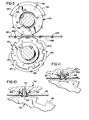
- Thus, to be effective, the crimps must be located along the web so as to avoid the holes. Accordingly, as can be seen in Fig. 1, the crimps are typically centered .25 inch (.635 cm) from the centers of adjacent holes, and are thereby separated from other crimps by an integer number of half-inches.
- The perforations separating successive forms represent yet another constraint on the location of the crimps. These cross perforations, typically formed on the web after crimping, must be located so as not to fall on the holes. Thus, as seen in Fig. 1, the perforations are also located .25 inch (.635 cm) from the centers of adjacent holes. It is not desirable, however, for the crimps to fall where a cross perforation will occur. In such a case, the crimps could cause premature, partial separation of individual forms along the perforation, thereby making accidental full separation much more likely. Moreover, the crimps prevent even, neat folding along the perforations, interfering with the proper arrangement of the web for storage and/or shipping.
- The separation between consecutive perforations along the web is, of course, determined by the desired length for the form. In the United States, the two most common lengths for forms are 8-1/2 inches (21.6 cm) and 11 inches (27.9 cm), and in Europe, the most common lengths are 8 inches (20.3 cm) and 12 inches (30.5 cm). In the case of 8-inch, 11-inch and 12-inch forms, as well as any other form of a length of an integer number of inches, it can be seen that consecutive perforations are separated by an even number of half-inch intervals. The crimp blades can therefore be arranged to provide crimps in intervals of an even number of half-inches. By separating the initial crimp from the initial perforation by an odd number of half-inch intervals, the perforations and crimps will not coincide.
- This approach is not usable in the case of 8-1/2 inch forms. With 8-1/2 inch forms (21.6 cm), the first and second cross perforations are separated by an odd number of half-inch intervals (17), but the first and third perforations are separated by an even number of such intervals (34). Therefore, with crimp blade spacing in an even number of half-inch intervals, it is not possible to prevent at least some crimps from coinciding with cross- perforations. Thus, it can be seen that a particular arrangement of crimp blades that is suitable for use with 11-inch forms is not usable with 8 1/2 inch forms, and vice versa.
- Typically, the problem of crimp spacing for different sizes of forms is solved by providing two different crimp blade holders, one size for each of the different forms. When the collator is to be readied for changing from one size form to another, the blade holders mounted to the rotatable shaft must be disassembled and removed from the shaft, and a new set of blade holders providing a different spacing must be installed. This represents a relatively time-consuming process, and requires the operator of the collator to keep two sets of crimp blade holders on hand. Moreover, two sets of parts is costly. In addition, it is necessary to change the gearing for driving the crimp blade holder shaft in synchronism with the web, which is also time-consuming and inconvenient.
- A second method is to rotate the crimp blade holder at different speeds, depending upon the size of the form. This method also requires a gearing change, and requires that with at least some sizes of forms, the blade holder must be rotated at a different speed than that of the web. The different speeds may result in tearing of the web by the crimp blades.
- What is needed, therefore, is a single set of crimp blade holders that are capable of use with either 8 1/2 or 11 inch forms. Such holders should be capable of arranging crimp blades such that in either case, crimps do not coincide with perforations along the multilayer web. Further, use of the crimp blade holders with one size of form following use with another size form should not require any modifications or adjustments to the blade holders, or changing of driving gears to synchronize crimping to form length.
- The present invention provides a crimp blade holder for attachment to a rotatable shaft for removably mounting a plurality of crimp blades. The holder, whicn is then used in crimping the edges of a moving web, mounts the blades such that the blade holder may be used during the production of either 8-1/2 or 11 inch forms.
- According to one aspect of the present invention, the blade holder includes a cylindrical body having a curved outer surface, with an axial bore defined through the cylindrical body for mounting the body to a shaft. Means securing the body to the snaft is provided, so tnat the body may be axially rotated thereby. Means for mounting the crimp blades to the body in predetermined fixed locations with respect to its outer surface is also provided so that rotation of the body causes the blades to crimp a web moving therepast. The diameter of the body and the positions of the blade mounting means on the outer surface are selected so that with 8 blades mounted to the body, rotation thereof causes crimps to be applied to the moving web with spacings thereon between successive crimps defining a repetitive pattern of substantially 2.0, 2.0, 2.0, 2.0, 2.0, 2.0, 2.0 and 3.0 inches (5.08, 5.08, 5.08, 5.08, 5.08, 5.08, 5.08 and 7.62 cm).
- The present invention further provides a method for crimping of a moving web, which includes the formation of the perforation at least partially across the web, substantially perpendicular to and crossing a line parallel to the direction of movement of the web. A first crimp is applied to the web along the line behind the perforation with respect to the direction of travel of the web, with a predetermined spacing from the perforation. Second, third, fourth, fifth, sixth, seventh, and eighth crimps are then applied to the web along the line, each crimp being applied at a spacing from the immediately preceding one of substantially 2.0 inches (5.08 cm). The next crimp is applied to the web along the line at a spacing from the preceding crimp of substantially 3.0 inches (7.62 cm). This crimp serves as the first crimp of the next repetition of the crimping pattern, followed by the second through eighth crimps as described above.
- Successive perforations are also applied to the web, each being formed with a spacing from the first perforation of either 8-1/2 or 11 inches, depending upon the length of the form being produced.
- Accordingly, it is an object of the present invention to provide a crimp blade holder for removably mounting a plurality of crimp blades for crimping a moving web in accordance with a predetermined pattern; to provide such a holder that will produce crimps along a moving web consisting of either 8-1/2 or 11 inch forms without coinciding with perforations along located along the web; to provide such a holder that is usable with any of several common sizes of forms; and to provide such a holder that is usable with several sizes of forms without requiring changing or modification of the holder when changing from production of one size forms to another.
- In order that the invention may be more readily understood, reference will now be made to the accompanying drawings, in which:
- Fig. 1 is a plan view of a portion of a multipart paper web, showing relative spacings therealong of registration holes, a perforation, and a crimp, in which the dimensions presented are in inches;
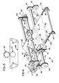
- Fig. 2 is an exploded perspective view of a crimp blade holder of the present invention for crimping one edge of a web;
- Fig. 3 is an end view of the crimp blade holder and a corresponding anvil surface member;
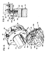
- Fig. 4 is a perspective, partially schematic view of an apparatus for crimping the edges of a paper web, including the crimp blade holders of the present invention;
- Fig. 5 is a schematic diagram of the path of the chain for advancing the web through the apparatus of Fig. 4;
- Fig. 6 is a perspective view of the assembled crimp blade holder of Fig. 2, also showing portions of a cooperating avnil surface member and the chain for advancing the web;
- Fig. 7 is a sectional view taken generally along line 7--7 of Fig. 6;
- Fig. 8 is a plan view of a portion of a multilayer web showing the locations of crimps produced by the crimp blade holder along a series of 8-1/2 inch (21.6 cm) forms, in which the dimensions are shown in inches;
- Fig. 9 is a plan view of a portion of a web showing the locations of crimps produced by the holder along a series of 11 inch (27.9 cm) forms;
- Fig. 10 is a sectional view of a portion of the crimp blade holder, illustrating the operation of a web stripping member; and
- Fig. 11 is a view similar to Fig. 10, further illustrating operation of the web stripping member.
- Referring generally to the drawings, and in particular to Fig. 2, a
crimp blade holder 20 is shown for removably mounting a plurality ofcrimp blades 22. The present invention is equally usable with a variety of types of conventional crimp blades, although for illustrative purposes, one type ofcrimp blade 22 is shown including twohalves 24. Eachblade 22 is also provided with a plurality ofteeth 26 for crimping a web, the outermost tips ofteeth 26 defining the leading edge ofblade 22. -
Blade holder 20 includes acylindrical body 28 having a plurality ofslots 30 located along the periphery ofbody 28. Aplate 32 is attached bybolts 34 to the end ofbody 28, thereby closing off one end of eachslot 30. Acrimp blade 22 may be inserted into each of theslots 30.Plate 32 provides for accurate positioning of ablade 22 within eachslot 30, with theblade 22 being inserted intoslot 30 so as toabut plate 32. - A pair of threaded
bores 36 are provided for eachslot 30 throughbody 28, opening into theslot 30 through one of its side walls. Each bore 36 is oriented to intersect the side wall perpendicular thereto, and opens at its opposite end along the periphery ofbody 28. Each bore 36 is adapted to receive aset screw 38, which may be advanced or retracted alongbore 36 by an appropriate tool, such as an Allen wrench (not shown). When acrimp blade 22 is inserted into aslot 30, theset screws 38 disposed within the corresponding bores 36 are advanced and tightened against theblade 22, thereby clampingblade 22 firmly in place. -
Body 28 andplate 32 each include acentral opening shaft 44.Groove 46 is provided extending the full length ofopening 40, and a threadedbore 50 extends throughbody 28, opening intoopening 40 throughgroove 46. Asimilar groove 52 is provided alongshaft 44, extending the full length of the outer surface thereof.Grooves body 28 and attachedplate 32 are mounted toshaft 44 to form a keyway for proper positioning ofbody 28 onshaft 44. A key (not shown) is inserted intogroove 52 ofshaft 44, and also fits intogroove 46 onbody 28. A set screw'54 engageable with threadedbore 50 is inserted intobody 50 and advanced toward and tightened against the key, thereby securingbody 28 in a desired position alongshaft 44. - The relative spacing between
adjacent slots 30 disposed along the periphery ofblade holder 20 for mountingblades 22 can be seen in Fig. 3. The eightslots 30 are arranged such that the distance between all but one of any adjacent pair ofblades 22 along a circle defined by the centers of the pitch line ofblades 22 and mounted withinslots 30, as indicated generally byarrows 56, is 2 inches (5.08 cm). One adjacent pair ofblades 22, however, are arranged such that the distance between the adjacent pair along the described circle is 3 inches (7.62 cm), indicated generally byarrow 58. Thus,blades 22 inserted intoslots 30 will produce a series of eight crimps along a web having a center to center spacing of 2.0, 2.0, 2.0, 2.0, 2.0, 2.0, 2.0, and 3.0 inches (5.08, 5.08, 5.08, 5.08, 5.08, 5.08, 5.08 and 7.62 cm) between adjacent crimps. - The
apparatus 60 with whichblade holder 20 is used for crimping a moving web is shown in schematic fashion in Fig. 4. A pair ofblade holders 20 and 20' are mounted toshaft 44 for providing crimps along both edges of a movingweb 62. It will be recognized by comparingblade holder 20 and blade holder 20' that the holders include both aleft hand holder 20 and a right hand holder 20'. While these holders are generally of identical construction, positioning ofgrooves 46 on thebodies 28 of each blade holder are such that theblade holders 20 and 20' are mounted toshaft 44 with relative circumferential positioning such that identical crimping patterns are produced on each edge ofweb 62 without any phase difference therebetween. -
Blade holders 20 and 2.01 are further distinguished by the direction from which threaded bores 36 (see Fig. 2) approach theblade mounting slots 30. By providing these variations inblade holders 20 and 20', it can be seen that an operator can manipulate setscrews 38 in either blade holder for insertion or removal ofblades 22 from the same side ofshaft 44. - A pair of
anvil surface members 70 and 70', to be described in detail below, are mounted to arotatable shaft 72. Eachanvil member 70 and 70' is provided with a plurality ofannular grooves 74 adapted such thatteeth 26 ofblades 22 will fit intogrooves 74. -
Anvil surface members 70 and 70' are mounted toshaft 72 using keys, keyways and set screws in a manner similar to that described above forblade holders 20 and 20'. Thus, the lateral positions ofblade holders 20 and 20' andanvil surface members 70 and 70' may be adjusted along their respective shafts. Thus, the crimping apparatus described herein may be used with forms of various widths, or may be used to place the crimps in location other than at the edges of the web. -
Shaft 72 is driven at one end bymotor 76 throughgears gear 84 is mounted to the opposite end ofshaft 72, and engages agear 86 mounted to one end ofshaft 44. Thus,motor 76 and gears 78 and 80 also driveshaft 44, rotating it in a direction indicated byarrow 88. -
Web 62 is passed betweenshafts arrow 90. During the crimping operation,shafts teeth 26 ofblades 22 mounted toblade holders 20 and 20' engage theannular grooves 74 ofanvil surface members 70 and 70'.Web 62 is passed alonganvil surface members 70 and 70', andteeth 26 ofblades 22perforate web 62, providing a plurality ofcrimps 92 along the edges ofweb 62.Crimps 92 are spaced to avoidregistration holes 93, already formed along both edges ofweb 62. -
Gears anvil surface members 70 and 70' and theteeth 26 ofblades 22 are rotated with a linear speed equal to the speed of the movingweb 62. - Each
anvil surface member 70 and 70' is provided with a cleaner 94 disposedadjacent member 70 on a side oppositeweb 62. Each cleaner 94 has a plurality offingers 96 extending one each into each of theannular grooves 74 ofmember 70 and 70'.Fingers 96 act during rotation ofmembers 70 and 70' to clear any paper dust or other debris fromgrooves 74. - In order to initially
thread web 62tnrough apparatus 60, or to replace or service any of the blade holders, crimp blades, and the like, it is necessary to moveblade holders 20 and 20' so thatblades 22 are out of engagement withweb 62. In order to disengage the blades, advance ofweb 62 is halted.Shaft 44 is then raised away fromweb 62, thereby raisingblades 22 fromanvil surface members 70 and 70'.Gears blades 22 andanvil surface members 70 and 70' is not lost, for reasons that will be explained below. - In order to raise and
lower shaft 44, a pair ofeccentric bearing housings 98 are provided near each end ofshaft 44.Bearings 100 are mounted into eachhousing 98 so thatshaft 44 is freely rotatable within thehousings 98, which in turn are journalled to a support frame (not shown). Agear 101 is mounted concentrically to an end of eachhousing 98. A pair ofgears 102, mounted to ashaft 104, engage gears 101.Shaft 104 may be rotated by ahandle 106 or the like, so that rotation ofhandle 106 rotates gears 101 and thus housings 98, raising and loweringshaft 44.Blades 22 are thereby moved into and out of operating position. - The
web 62 is advanced throughapparatus 60 by a pair of drivenchains 108. Eachchain 108 is engaged with a plurality of cooperatingsprockets 110, as shown schematically in Fig. 5, at least one of which is driven so as to movechain 108 at a speed identical to that of the advance ofweb 62. - Referring to Fig. 6,
chain 108 may be seen in some detail.Links 112 and connectinglinks 114 are attached by riveting in conventional fashion. A plurality of connectinglinks 116 having a support arm, or outrigger, 118 integrally attached thereto are periodically substituted for connectinglinks 114 along one side of each ofchains 108. Apin 120 is mounted near the outer end of eachsupport arm 118, and is of a size so as to fit within the registration holes provided along the edges ofweb 62. Engagement of the registration holes withpins 120, in conjunction with driving movement ofchains 108, advancesweb 62 as seen by reference back to Fig. 4. - The construction of the
anvil surface member 70 is shown in detail in Figs. 6 and 7. Ahub 122 is provided with acentral opening 124 for placement ofhub 122 onshaft 72. Agroove 126 extends the length ofopening 124, and cooperates with a similar groove placed along the length ofshaft 72 for insertion thereinto of a key 128 for holdinghub 122 in circumferential position onshaft 72. A threaded bore extends radially throughhub 122 and communicates withgroove 126 for insertion thereinto of aset screw 130. Advancement ofset screw 130 into the threaded opening by an Allen wrench (not shown), or the like, againstkey 128 secureshub 122 in place alongshaft 72. - An
annular flange 132 extends aroundhub 122 at one end thereof. A plurality ofannular plates 134 of alternating heights are positioned onhub 122 againstflange 132, for defining the plurality ofgrooves 74 into which theteeth 26 ofcrimp blade 22 are inserted for crimpingweb 62. Anannular spacer 136 is placed onhub 122adjacent plates 134, and is secured in place to flange 132 by a plurality ofbolts 138 or the like. - Because the crimps formed along the edges of
web 62 are typically placed along the same longitudinal line as the registration holes, it is often necessary forpins 120 and supportingarms 118 to be passed through the area in which thecrimp blades 22 are cooperating with theanvil surface member 70 to crimp the web. To enablepins 120 and supportarms 118 to pass through this area, a plurality ofslots 140 are formed in theanvil surface member 70, extending acrossflange 132,plates 134, andspacer 136. As eachpin 120 and supportingarm 118 is moved toanvil surface member 70 bychain 108,pin 120 andarm 118 will enter aslot 140 as seen in Fig. 7. This contact withmember 70 is avoided. - The relative placement of the
slots 140 about the periphery ofanvil surface member 70 may seen by reference back to Fig. 3. During rotation ofblade holder 20 andanvil surface member 70,crimp blades 22 carried byholder 20 cannot be permitted to align with one of theslots 140 since not only will a crimp be incompletely or improperly formed, but theblade 22 will also strike one ofpins 120 which is being moved through theslot 140. Thus, eightslots 140 are provided around the periphery ofanvil supporting member 70, with the center-to-center spacing between all but one adjacent pair ofslots 140 being 2.0 inches (5.08 cm) as indicated generally byarrows 142. One pair of adjacent slots, however, are arranged so that the distance between theslots 140 is 3.0 inches (7.62 cm), indicated byarrow 144. Theanvil surface member 70 is then circumferentially positioned with respect toblade holder 20 so that eachcrimp blade 22 carried byholder 20 will engage the grooves ofanvil supporting member 70 between one pair ofslots 140. - It will also be readily seen that it is necessary for
pins 120 to be provided with a spacing compatible with theslots 140 defined onanvil surface member 70. Therefore, connectinglinks 116, along with the attachedsupport arm 118 andpin 120, are provided along eachchain 108 in repetitive sets of eight having a center-to-center spacing of 2.0, 2.0, 2.0, 2.0, 2.0, 2.0, 2.0, and 3.0 inches (5.08, 5.08, 5.08, 5.08, 5.08, 5.08, 5.08 and 7.62 cm). - The crimp pattern produced by
blade holder 20 is shown in Figs. 8 and 9. It will be understood that all spacing dimensions described in connection therewith represent the center-to-center spacings of the items in question. In Fig. 8, a portion of the edge of aweb 62 is shown for illustrating the application of the crimps in the case of 8-1/2 inch (21.6 cm) forms.Holes 93 are provided along the edge ofweb 62, with a spacing of .50 inch (1.27 cm) betweenadjacent holes 93, illustrated byarrows 148. Aperforation 150 extends acrossweb 62, centered .25 inch (.635 cm) betweenadjacent holes 93, defining the division between successive forms. The location ofperforation 150 is at a position alongweb 62 designated, for purposes of discussion, as 0" (0 cm). - The
first crimp 92a of the crimp pattern is applied toweb 62 1.0 inch (2.54 cm) belowperforation 150, as indicated byarrow 152. The next succeedingcrimps arrows 154.Crimps 92d through 92h follow in similar fashion. - A
perforation 156 defines the beginning of the next succeeding form at a position indicated as 8.50" (21.6 cm), located with a spacing of .50 inch (1.27 cm) fromcrimp 92e. Similarly, perforation 158, located at the 17.00" (43.2 cm) position, defines the beginning of the next following form. - Following the application of
crimp 92h toweb 96, the next succeedingcrimp 92a' will be produced onweb 62 with a spacing of 3.0 inches (7.62 cm) fromcrimp 92h, as indicated byarrows 62. It will be noticed, however, that since eight crimps have already been placed onweb 106, corresponding to one for each of the eightcrimp blades 22 carried byblade holder 20, the crimp pattern has been begun again. Thus, the crimp pattern demonstrated bycrimps 92a through 92a' will be repeated in similar fashion. - Additional perforations are continuously located on
web 62 at 8.50 inch (21.6 cm) intervals. As can be seen from Fig. 8, none of thecrimps 92 applied toweb 62 will coincide with any ofperforations web 62, the next succeedingcrimp 92a' is located at a spacing from perforation 158 of 1.0 inch (2.54 cm), indicated byarrow 162. It will be seen that this is identical to the spacing betweenperforation 150 and crimp 92a, and thus the entire pattern illustrated by Fig. 8 will be continuously repeated. It can therefore be seen that in no instance will any ofcrimps 92 coincide with any perforation. - As the
crimps 92 are being applied toweb 62,web 62 is being carried through the apparatus by chains 108 (shown in Fig. 4) throughpins 120 which engage various ones of registration holes 93. As can be seen oy reference to Fig. 3, theparticular holes 93 with which pins 120 are engaged cannot be immediately adjacent to acrimp 92, since thepin 120 and its associatedsupport arm 118 must pass through one of theslots 140 carried onanvil support member 70. Accordingly, as shown in Fig. 8, apin 120 will be engaged with thehole 93 designated ashole 93p betweencrimps pin 120 could alternatively engagehole 93p'.) - Since the registration pins 120 are carried by
chain 108 with a relative spacing identical to that with which the crimps are applied, eachhole 93p with which apin 120 is engaged will be spaced from the immediately preceding crimp by an equal amount. Thus, a series ofholes 93p are shown, each following acrimp 92 by an interval of 0.75" (1.90 cm). - The crimp pattern produced during the manufacture of 11 inch (27.9 cm) forms is shown in Fig. 9. Here, two consecutive sections of the edge of a
web 62 are shown, in which holes 93 have been again formed with a spacing betweenadjacent holes 93 of .50 inch (1.27 cm). Aperforation 170, located alongweb 62 at a position arbitrarily designated 0", defines the division between a pair of successive forms. In this case, however, thefirst crimp 92a of the crimp pattern is positioned with a spacing of only .50 inch (1.27 cm) fromperforation 170, as indicated byarrows 172. As has been previously described,successive crimps 92b through 92h of the crimp pattern are formed at 2.0 inch (5.08 cm) intervals, with the repetition of the pattern beginning withcrimp 92a', which is spaced fromcrimp 92h by 3.0 inches (7.62 cm). -
Successive perforations 174 are provided alongweb 62 at intervals of 11.0 inches (27.9 cm). While in this case, the entire pattern of crimps and perforations will not begin to repeat until the 187.00" (475.0 cm) position (not shown), it should be recognized that all successive crimps are separated by an integral number of inches. Since successive perforations are separated by an integral number of inches, and since theinitial crimp 92a is separated fromperforation 170 by .50 inch (1.27 cm), none ofcrimps 92 will coincide with any ofperforations 174. Further,blade holder 20 is thus suitable for use with any form having a length of an integral number of inches, such as 8 inch (20.3 cm) or 12 inch (30.5 cm) forms. - In using a toothed crimp blade such as
blade 22 for the crimping of a multipart web, withdrawal of the blade teeth from the web during the crimping operation tends to cause "plucking" of the web. In such a case, withdrawal of the blade teeth from the web causes all or some of the web parts, or layers, to be lifted upward from their normal path of travel in the region of the newly- formed crimp. This can damage the strength of the crimp, possibly resulting in unwanted separation or improper registration of the various parts of the finished form. - Referring back to Fig. 2, plucking is prevented by providing
blade holder 20 with a plurality ofweb stripping members 180 mounted tobody 28 around theteeth 26 of eachblade 22 when mounted toholder 20.Members 180 are constructed of a resilient material, preferably molded from a polyurethane material, and include abase portion 182 and an outwardly extendingflange portion 184.Flange 184 is adapted to surroundteeth 26 ofblade 22 on three sides and extends to a normal height even with the outermost tips ofteeth 26 when in position onholder 20. -
Member 180 is mounted toportion 32 by a pair ofbuttons 186 which pass through a pair of holes defined in thebase 182 ofmember 180.Buttons 186 are in turn secured withinbody 28, and may be formed, for example, by screws driven into the outer surface ofbody 28. Becausemember 180 is constructed of a resilient material, it may be mounted tobody 28 by snapping the openings inbase 182 over the heads ofbuttons 186, and may be removed frombody 28 in reverse fashion. Thus, installation and/or replacement are facilitated. - Since the web stripping members are molded as a single piece, they can be manufactured quite inexpensively, thereby making their use practical. Moreover, since installation of
buttons 186 onto a blade holder is easily accomplished by driving screws into the holder surface, use of themembers 180 with presently-existing blade holders on a retrofit basis can be easily carried out. - The operation of
web stripping member 180 may be seen by reference to Figs. 10 and 11. In Fig. 10, theteeth 26 ofblade 22 have been inserted throughweb 62 for crimping thereof. Whenteeth 26 enter thegrooves 74 withinanvil surface member 70,flange 184 ofmember 180 is compressed betweenanvil surface member 70 andblade holder 20. In Fig. 11, as rotation ofblade holder 20moves blade 22 andmember 180 beyondanvil surface member 70, the resiliency ofmember 180 causes flange 184 to return to its original height substantially equal to the height of the tips ofteeth 26. This resilient force is exerted downwardly upon theweb 62, pushing it from engagement withteeth 26, thereby preventing plucking of the web by theblade 22. - One consideration associated with the use of
web stripping members 180 arises from the frequent use of multipart forms for generating multiple copies of a single form. In such cases, carbon paper is either interspersed between the various parts of the multipart web, or "carbonless" paper is used for the individual parts, in which pressure on the outermost part is transferred as markings to the underlying parts. - Because the web-stripping
members 180 apply a force to the web to urge it from the teeth of thecrimp blades 22, eachmember 180 leaves an impression, or "footprint", of the U-shaped member on the underlying parts of the web around the crimps. This footprint can be objectionable if it is too dark or intrudes into the usable portion of the form. - One approach to minimizing the effect of the footprint is to carefully confine it to a portion of the form which is typically discarded. Referring back to Fig. 8, a
longitudinal perforation 188 is typically applied near each edge of the form, typically spaced from 1/2 to 5/8 inches (1.27 to 1.59 cm) from the form edge.Perforation 188 then defines aregion 190 of the form usually referred to as the "stub". Thestub 190 contains the registration holes 93 and thecrimps 92 and, after the form has been used,stub 190 is generally separated from the remainder of the form and discarded. Thus, if the web-strippingmembers 180 are carefully sized so that the footprint occurs only withinstub 190, removal and discarding of thestub 190 will eliminate the footprints as well. - A second approach, which can be used in conjunction with the approach set forth above, is to select a hardness for the polyurethane material comprising the
members 180 that is sufficiently hard to be effective in stripping the web fromblades 22, but yet is sufficiently soft to minimize or eliminate the footprints. It has been found that a hardness of approximately 55-60 on the Shore A scale produces little marking of the form, yet is effective in stripping theweb 62 from theblades 22.
Claims (6)
1. A holder mounting a plurality of crimp blades (22) for crimping of a moving web, including:
a cylindrical body (28) having a curved outer surface;
an axial bore (40) defined through said cylindrical body (28) for mounting said body to a shaft (44);
means (54) securing said body (28) to the shaft (44) such that said body may be axially rotated thereby; and
means (30, 38) for mounting the crimp blades (22) to said body (28) in predetermined fixed locations with respect to said outer surface such that rotation of said body causes the blades to crimp a web (62) moving therepast;
characterized by:
the diameter of said body (28) and the positions of said blade mounting means (30, 38) on said surface thereof being selected so that with a plurality of blades (22) mounted to said body, rotation thereof causes crimps (92) to be applied to the moving web (62) with spacings thereon between successive crimps defining a repetitive pattern of substantially 2.0, 2.0, 2.0, 2.0, 2.0, 2.0, 2.0 and 3.0 inches (5.08, 5.08, 5.08, 5.08, 5.08, 5.08, 5.08 and 7.62 cm).
2. A holder as defined in claim 1, wherein said blade holding means includes eight slots (30) defined in said outer surface of said body (28), and means (38) for securing one of the crimp blades (22) within each of said slots.
3. A method of applying crimps (92) to a moving web (62) along a line parallel to the direction of movement of the web, characterised by the steps of:
(a) applying a first crimp (92a) to the web;
(b) applying a next crimp (92b) to the web at a spacing from the preceding one of said crimps of substantially 2.0 (5.08 cm) inches;
(c) applying a next crimp (92c) to the web at a spacing from the preceding one of said crimps of substantially 2.0 inches (5.08 cm);
(d) applying a next crimp (92d) to the web at a spacing from the preceding one of said crimps of substantially 2.0 inches (5.08 cm);
(e) applying a next crimp (92e) to the web at a spacing from the preceding one of said crimps of substantially 2.0 inches (5.08 cm);
(f) applying a next crimp (92f) to the web at a spacing from the preceding one of said crimps of substantially 2.0 inches (5.08 cm);
(g) applying a next crimp (92g) to the web at a spacing from the preceding one of said crimps of substantially 2.0 inches (5.08 cm);
(h) applying a next crimp (92h) to the web at a spacing from the preceding one of said crimps of substantially 2.0 inches; (5.08 cm)
(i) applying a next crimp (92a') to the web at a spacing from the preceding one of said crimps of substantially 3.0 inches (7.62 cm); and
(j) repeating at least once steps (b) through (i).
4. A method as defined in claim 3, comprising the further steps of:
forming a perforation (150) at least partially across the web (62), substantially perpendicular to and crossing said line, said perforation (150) being formed ahead of said first crimp (92a) with respect to the direction of travel of the web with a spacing from said first crimp of substantially 1.0 inch (2.54 cm); and
forming a plurality of additional perforations (156, 158), each of said perforations being formed with a spacing from the preceding one of said perforations of substantially 8.50 inches (21.6 cm).
5. A method as defined in claim 3, comprising the further steps of:
forming a perforation (170) at least partially across the web (62), substantially perpendicular to and crossing said line, said perforation (170) being formed with a spacing from said first crimp (92a) of substantially .50 inch (1.27 cm); and
forming a plurality of additional perforations (174), each of said perforations being formed with a spacing from the preceding one of said perforations of substantially an integer multiple of 1.0 inch (2.54 cm).
6. A method as defined in claims 3, 4 or 5, comprising the further step of forming a plurality of holes (93) through the web (62) along said line, each of said holes (93) being formed with a spacing from the preceding one of said holes of substantially 0.50 inch (1.27 cm), one of said holes further being formed with a spacing from said first crimp (92a) of substantially 0.25 inch (.635 cm).
Applications Claiming Priority (2)
| Application Number | Priority Date | Filing Date | Title |
|---|---|---|---|
| US534514 | 1983-09-21 | ||
| US06/534,514 US4536176A (en) | 1983-09-21 | 1983-09-21 | Crimp blade holder |
Publications (1)
| Publication Number | Publication Date |
|---|---|
| EP0138422A1 true EP0138422A1 (en) | 1985-04-24 |
Family
ID=24130387
Family Applications (1)
| Application Number | Title | Priority Date | Filing Date |
|---|---|---|---|
| EP84306443A Withdrawn EP0138422A1 (en) | 1983-09-21 | 1984-09-20 | Crimp blade holder |
Country Status (3)
| Country | Link |
|---|---|
| US (1) | US4536176A (en) |
| EP (1) | EP0138422A1 (en) |
| CA (1) | CA1234007A (en) |
Cited By (3)
| Publication number | Priority date | Publication date | Assignee | Title |
|---|---|---|---|---|
| GB2255305A (en) * | 1991-04-11 | 1992-11-04 | Heidelberger Druckmasch Ag | Assuring orderly web travel in a folder |
| US5186444A (en) * | 1991-04-11 | 1993-02-16 | Heidelberg Harris Gmbh | Method and device for assuring orderly web travel in a folder by punching holes in a paper width direction |
| WO1998053966A1 (en) * | 1997-05-29 | 1998-12-03 | Moore U.S.A., Inc. | Apparatus and method for selectively making longitudinal perforations on web materials |
Families Citing this family (9)
| Publication number | Priority date | Publication date | Assignee | Title |
|---|---|---|---|---|
| US4842260A (en) * | 1987-12-04 | 1989-06-27 | Continuous Graphics, Inc. | Modular collating assembly |
| US6332149B1 (en) | 1995-06-07 | 2001-12-18 | R. R. Donnelley & Sons | Imposition process and apparatus for variable imaging system |
| US6952801B2 (en) | 1995-06-07 | 2005-10-04 | R.R. Donnelley | Book assembly process and apparatus for variable imaging system |
| US6327599B1 (en) * | 1995-06-07 | 2001-12-04 | R. R. Donnelley & Sons Company | Apparatus for controlling an electronic press to print fixed and variable information |
| US6205452B1 (en) | 1997-10-29 | 2001-03-20 | R. R. Donnelley & Sons Company | Method of reproducing variable graphics in a variable imaging system |
| US6246993B1 (en) | 1997-10-29 | 2001-06-12 | R. R. Donnelly & Sons Company | Reorder system for use with an electronic printing press |
| US6088710A (en) * | 1997-10-29 | 2000-07-11 | R.R. Donnelley & Sons Company | Apparatus and method for producing fulfillment pieces on demand in a variable imaging system |
| US5911702A (en) * | 1997-11-06 | 1999-06-15 | Heartport, Inc. | Methods and devices for cannulating a patient's blood vessel |
| US7278094B1 (en) | 2000-05-03 | 2007-10-02 | R. R. Donnelley & Sons Co. | Variable text processing for an electronic press |
Citations (2)
| Publication number | Priority date | Publication date | Assignee | Title |
|---|---|---|---|---|
| US2935002A (en) * | 1957-06-28 | 1960-05-03 | Jr Bailey P Robinson | Mechanism for producing a manifolding assembly interlock |
| US3215049A (en) * | 1963-01-23 | 1965-11-02 | Bobst J | Waste picking devices |
Family Cites Families (3)
| Publication number | Priority date | Publication date | Assignee | Title |
|---|---|---|---|---|
| US3727908A (en) * | 1970-08-17 | 1973-04-17 | Harris Intertype Corp | Continuous business forms |
| US4114869A (en) * | 1977-03-28 | 1978-09-19 | Didde-Glaser, Inc. | Mechanism for effecting interlock of multiple sheet continuous business forms |
| US4422630A (en) * | 1982-05-14 | 1983-12-27 | Harris Corporation | Blade holder and method of using the same |
-
1983
- 1983-09-21 US US06/534,514 patent/US4536176A/en not_active Expired - Lifetime
-
1984
- 1984-09-05 CA CA000462417A patent/CA1234007A/en not_active Expired
- 1984-09-20 EP EP84306443A patent/EP0138422A1/en not_active Withdrawn
Patent Citations (2)
| Publication number | Priority date | Publication date | Assignee | Title |
|---|---|---|---|---|
| US2935002A (en) * | 1957-06-28 | 1960-05-03 | Jr Bailey P Robinson | Mechanism for producing a manifolding assembly interlock |
| US3215049A (en) * | 1963-01-23 | 1965-11-02 | Bobst J | Waste picking devices |
Cited By (6)
| Publication number | Priority date | Publication date | Assignee | Title |
|---|---|---|---|---|
| GB2255305A (en) * | 1991-04-11 | 1992-11-04 | Heidelberger Druckmasch Ag | Assuring orderly web travel in a folder |
| US5186444A (en) * | 1991-04-11 | 1993-02-16 | Heidelberg Harris Gmbh | Method and device for assuring orderly web travel in a folder by punching holes in a paper width direction |
| GB2255305B (en) * | 1991-04-11 | 1994-09-07 | Heidelberger Druckmasch Ag | Method and device for assuring orderly web travel in a folding device |
| WO1998053966A1 (en) * | 1997-05-29 | 1998-12-03 | Moore U.S.A., Inc. | Apparatus and method for selectively making longitudinal perforations on web materials |
| US6050927A (en) * | 1997-05-29 | 2000-04-18 | Moore U.S.A., Inc. | On-demand skip perforating |
| US6460441B1 (en) | 1997-05-29 | 2002-10-08 | Moore North America, Inc. | On-demand skip perforating |
Also Published As
| Publication number | Publication date |
|---|---|
| CA1234007A (en) | 1988-03-15 |
| US4536176A (en) | 1985-08-20 |
Similar Documents
| Publication | Publication Date | Title |
|---|---|---|
| US4536176A (en) | Crimp blade holder | |
| US4295842A (en) | Stripping device for removing waste sheet board | |
| JP3271048B2 (en) | Sheet feed shaft, manufacturing apparatus and manufacturing method thereof | |
| CA1223194A (en) | File hole punch ring apparatus for web fed paper conveying mechanism | |
| JP3123753B2 (en) | Equipment for stripping scrap from die-cut blanks | |
| DK167969B1 (en) | ELEVATIVE COURT AND APPLIANCE FOR PUTTING IT INTO A MACHINE | |
| WO1997023398A1 (en) | Method and device for perforating and/or cutting and/or scoring a web. | |
| DE3430739A1 (en) | METHOD FOR CUTTING AND PUNCHING AND DELIVERING STICKERS OF DIFFERENT SHAPES | |
| US4037501A (en) | Through-the-cylinder slug out device | |
| US5045045A (en) | Skip-scorer, skip-perforator for use with printing press systems | |
| EP2279954A2 (en) | Cutting device, method for cutting labels and labelling device | |
| US3768801A (en) | Apparatus and method for making multiple ply sets | |
| EP0219890B1 (en) | Shift device | |
| US6681666B2 (en) | Method and apparatus for scrap removal from rotary dies | |
| US4601693A (en) | Apparatus for crimping a moving web | |
| US4422630A (en) | Blade holder and method of using the same | |
| EP0301684B1 (en) | Perforating device for manifold forms | |
| JP2003127094A (en) | Device for making various punching patterns in paper sheetlike printed book | |
| EP0347087A2 (en) | Notch cylinder unit | |
| CA1077539A (en) | Mechanism for effecting interlock of multiple sheet continuous business forms | |
| DE2603906A1 (en) | PRESSURE DEVICE IN THE FORM OF A PRINT DRUM EQUIPPED WITH PRINT WHEELS | |
| US2736380A (en) | Rotary cut-off assembly with a pull-out roll | |
| US4005810A (en) | Continuous library catalog card | |
| EP0259433B1 (en) | Improvement in the apparatus for carrying out cross perforations on a paper band | |
| JP3381768B2 (en) | A roll-shaped continuous band that can be separated for each unit pattern printing, a method of manufacturing the same, and a manufacturing apparatus thereof. |
Legal Events
| Date | Code | Title | Description |
|---|---|---|---|
| PUAI | Public reference made under article 153(3) epc to a published international application that has entered the european phase |
Free format text: ORIGINAL CODE: 0009012 |
|
| AK | Designated contracting states |
Designated state(s): DE FR GB |
|
| STAA | Information on the status of an ep patent application or granted ep patent |
Free format text: STATUS: THE APPLICATION IS DEEMED TO BE WITHDRAWN |
|
| 18D | Application deemed to be withdrawn |
Effective date: 19860331 |
|
| RIN1 | Information on inventor provided before grant (corrected) |
Inventor name: GASPAR, RICHARD A. |