EP0140137A2 - Keyless entry system for automotive devices with feature for giving caution for locking wireless code transmitter in vehicle - Google Patents
Keyless entry system for automotive devices with feature for giving caution for locking wireless code transmitter in vehicle Download PDFInfo
- Publication number
- EP0140137A2 EP0140137A2 EP19840111197 EP84111197A EP0140137A2 EP 0140137 A2 EP0140137 A2 EP 0140137A2 EP 19840111197 EP19840111197 EP 19840111197 EP 84111197 A EP84111197 A EP 84111197A EP 0140137 A2 EP0140137 A2 EP 0140137A2
- Authority
- EP
- European Patent Office
- Prior art keywords
- transmitter
- signal
- code
- keyless entry
- entry system
- Prior art date
- Legal status (The legal status is an assumption and is not a legal conclusion. Google has not performed a legal analysis and makes no representation as to the accuracy of the status listed.)
- Granted
Links
Images


Classifications
-
- B—PERFORMING OPERATIONS; TRANSPORTING
- B60—VEHICLES IN GENERAL
- B60R—VEHICLES, VEHICLE FITTINGS, OR VEHICLE PARTS, NOT OTHERWISE PROVIDED FOR
- B60R25/00—Fittings or systems for preventing or indicating unauthorised use or theft of vehicles
- B60R25/20—Means to switch the anti-theft system on or off
- B60R25/24—Means to switch the anti-theft system on or off using electronic identifiers containing a code not memorised by the user
- B60R25/246—Means to switch the anti-theft system on or off using electronic identifiers containing a code not memorised by the user characterised by the challenge triggering
-
- G—PHYSICS
- G07—CHECKING-DEVICES
- G07C—TIME OR ATTENDANCE REGISTERS; REGISTERING OR INDICATING THE WORKING OF MACHINES; GENERATING RANDOM NUMBERS; VOTING OR LOTTERY APPARATUS; ARRANGEMENTS, SYSTEMS OR APPARATUS FOR CHECKING NOT PROVIDED FOR ELSEWHERE
- G07C9/00—Individual registration on entry or exit
- G07C9/00174—Electronically operated locks; Circuits therefor; Nonmechanical keys therefor, e.g. passive or active electrical keys or other data carriers without mechanical keys
- G07C9/00309—Electronically operated locks; Circuits therefor; Nonmechanical keys therefor, e.g. passive or active electrical keys or other data carriers without mechanical keys operated with bidirectional data transmission between data carrier and locks
- G07C2009/00388—Electronically operated locks; Circuits therefor; Nonmechanical keys therefor, e.g. passive or active electrical keys or other data carriers without mechanical keys operated with bidirectional data transmission between data carrier and locks code verification carried out according to the challenge/response method
- G07C2009/00404—Electronically operated locks; Circuits therefor; Nonmechanical keys therefor, e.g. passive or active electrical keys or other data carriers without mechanical keys operated with bidirectional data transmission between data carrier and locks code verification carried out according to the challenge/response method starting with prompting the lock
-
- G—PHYSICS
- G07—CHECKING-DEVICES
- G07C—TIME OR ATTENDANCE REGISTERS; REGISTERING OR INDICATING THE WORKING OF MACHINES; GENERATING RANDOM NUMBERS; VOTING OR LOTTERY APPARATUS; ARRANGEMENTS, SYSTEMS OR APPARATUS FOR CHECKING NOT PROVIDED FOR ELSEWHERE
- G07C9/00—Individual registration on entry or exit
- G07C9/00174—Electronically operated locks; Circuits therefor; Nonmechanical keys therefor, e.g. passive or active electrical keys or other data carriers without mechanical keys
- G07C2009/00753—Electronically operated locks; Circuits therefor; Nonmechanical keys therefor, e.g. passive or active electrical keys or other data carriers without mechanical keys operated by active electrical keys
- G07C2009/00769—Electronically operated locks; Circuits therefor; Nonmechanical keys therefor, e.g. passive or active electrical keys or other data carriers without mechanical keys operated by active electrical keys with data transmission performed by wireless means
- G07C2009/00793—Electronically operated locks; Circuits therefor; Nonmechanical keys therefor, e.g. passive or active electrical keys or other data carriers without mechanical keys operated by active electrical keys with data transmission performed by wireless means by Hertzian waves
-
- G—PHYSICS
- G07—CHECKING-DEVICES
- G07C—TIME OR ATTENDANCE REGISTERS; REGISTERING OR INDICATING THE WORKING OF MACHINES; GENERATING RANDOM NUMBERS; VOTING OR LOTTERY APPARATUS; ARRANGEMENTS, SYSTEMS OR APPARATUS FOR CHECKING NOT PROVIDED FOR ELSEWHERE
- G07C2209/00—Indexing scheme relating to groups G07C9/00 - G07C9/38
- G07C2209/60—Indexing scheme relating to groups G07C9/00174 - G07C9/00944
- G07C2209/63—Comprising locating means for detecting the position of the data carrier, i.e. within the vehicle or within a certain distance from the vehicle
-
- Y—GENERAL TAGGING OF NEW TECHNOLOGICAL DEVELOPMENTS; GENERAL TAGGING OF CROSS-SECTIONAL TECHNOLOGIES SPANNING OVER SEVERAL SECTIONS OF THE IPC; TECHNICAL SUBJECTS COVERED BY FORMER USPC CROSS-REFERENCE ART COLLECTIONS [XRACs] AND DIGESTS
- Y10—TECHNICAL SUBJECTS COVERED BY FORMER USPC
- Y10T—TECHNICAL SUBJECTS COVERED BY FORMER US CLASSIFICATION
- Y10T70/00—Locks
- Y10T70/50—Special application
- Y10T70/5889—For automotive vehicles
- Y10T70/5973—Remote control
- Y10T70/5978—With switch
Definitions
- the present invention relates generally to a unique and novel keyless entry system for operating automotive devices, such as door locks, a trunk lid lock, a glove box lid lock, steering lock devices and/or a starter motor without mechanical keys. More specifically, the invention relates to a keyless entry system which comprises a wireless transmitter transmitting a preset code to a controller which actuates the automotive devices when the code from the transmitter matches a preset code stored in the controller. Additionally, the invention relates to an alarm or cautioning means associated with the keyless entry system for producing an alarm or a caution when a user leaves the transmitter in the passenger compartment and starts to leave the vehicle.
- automotive devices such as door locks, a trunk lid lock, a glove box lid lock, steering lock devices and/or a starter motor without mechanical keys. More specifically, the invention relates to a keyless entry system which comprises a wireless transmitter transmitting a preset code to a controller which actuates the automotive devices when the code from the transmitter matches a preset code stored in the controller. Additionally, the invention relates to an alarm
- U.S. Patent 4,205,325 discloses a keyless entry system for an automotive vehicle permitting a plurality of operations to be achieved _from outside the vehicle by one who is knowledgeable of predetermined digital codes. Functions such as unlocking the doors of the vehicle, opening the rear trunk lid, opening a roof window, lowering the windows or programming the system with a user-preferred digital access code can all be performed by proper sequential operation of a digital keyboard mounted on the outside of the vehicle.
- the present invention provides a novel and more useful system for operating the vehicle devices without an ignition key and without requiring manual entry of a predetermined code.
- Another and more specific object of the present invention is to provide a keyless entry system including an electronic controller which actuates an automotive device in response to a preset code-indicative signal transmitted by a wireless signal transmitter.
- a further object of the present invention is to provide an alarm or caution system which notifies the vehicle user of cases where the transmitter remains inside the passenger compartment while the user is preparing-to leave the vehicle.
- a keyless entry system in accordance with the present invention, generally comprises a wireless code transmitter which is portable by hand or in pockets and has an enclosed battery acting as a power source, and a controller connected to vehicle devices to electrically operate the latter in response to a preset code transmitted from the transmitter.
- the transmitter transmits a code signal to the controller when one of the vehicle devices is to be operated.
- the controller is responsive to the code signal when the transmitted code matches a preset code to produce a driver signal which actuates the designated vehicle device.
- a switch which activates the transmitter is provided on the external surface of the vehicle body and connected to the controller.
- the controller transmits a demand signal to the transmitter possessed by the user.
- the transmitter responds to the demand signal by transmitting the code signal to the controller.
- Another and important feature of the invention is to provide a caution system which detects when the transmitter is locked in the vehicle, and produces an alarm in such cases.
- the locking transmitter in the vehicle caution means monitors the amplitude of the signal receiver from the transmitter and produces an alarm when the signal level remains within a given range for a given period of time.
- the given period of time should be selected to be long enough for the user to walk a certain distance away from the vehicle but short enough to produce the alarm before the user goes too far away to recognize the caution.
- a keyless entry system for operting an automotive vehicle device without a mechanical key comprises an electrical actuator associated with the lock device and responsive a control signal to reverse the position of the lock device, a manual switch manually, a transmitter activated by manual operation of the manual switch to output a radio signal indicative of a unique code which identifies the transmitter, a battery for supplying electric power to the transmitter, a controller for receiving the radio signal from the transmitter, comparing the unique code indicated by the radio signal with a preset code, and producing the control signal when the unique code matches the preset code, and a transmitter-locking alarm means, associated with the controller, for detecting when the transmitter is locked in the vehicle and producing an alarm in such cases.
- a keyless entry system for an automotive vehicle for operating one of a plurality of vehicle devices including a door lock device which is selective operated to either of a first locked position and a second unlocked position, comprises a plurality of electrical actuators respectively associated with the corresponding vehicle devices and responsive a control signal to operate the corresponding vehicle device to desired position, a plurality of manual switches, each adapted to be operated for operating one of the corresponding vehicle devices, a transmitter activated by manual operation of one of the manual switches to output a radio signal indicative of a unique code which identifies the transmitter, a controller for receiving the radio signal from the transmitter, comparing the unique code indicated by the radio signal with a preset code, and producing the control signal when the unique code matches the preset code, the controller including means responsive to manual operation of one of the manual switch for identifying one of the actuators to be operated and operating the identified- actuator for operating one of the vehicle devices corresponding to the manual switch operated, and a transmitter-locking alarm means, associated with the controller, for detecting when
- the preferred embodiment of a keyless entry system for an automotive vehicle generally comprises a code transmitter 100 and a controller 200.
- the controller 200 is connected via a driver signal generator 204 to actuators 202 for vehicle devices such as door lock device, a trunk lid lock device, a starter motor and a steering lock device.
- the controller 200 includes a demand signal SD generator 208 which sends a demand signal SD to the transmitter 100 to activate the latter.
- the demand signal SD generator 208 is connected to one or more manual switches 210 which are placed on the external surface of the vehicle so as to be accessible from outside the vehicle.
- the demand signal SD generator 208 produces a demand signal SD when one of the manual switches 210 is depressed.
- the transmitter 100 includes a receiver circuit 102 for receiving the demand signal SD from the controller.
- the transmitter 100 becomes active when the receiving circuit 102 receives the demand signal SD to produce a code signal SC which is indicative of a preset specific code.
- the preset code of the portable transmitter 100 differs from that of the demand signal SD generator 208 so that the controller 200 can recognize when the transmitter 100 is responding.
- the transmitter 100 encloses a thin, compact, long-life battery 304, such as a mercury battery, acting as a power source.
- the battery 304 is connected to a transmitter circuit to supply electric power.
- the transmitter 100 continuously transmits the code signal SC to the controller for as long as it remains active.
- the code signal SC is received by a receiver 212 in the controller 200.
- the controller 200 has a comparator 213 to compare the received code with a specific preset code. When the received code matches the code preset as compared in the comparator 215, the controller 200 sends a control signal SL to the driver circuit generator 204.
- the driver signal generator 204 in turn sends a drive signal to one of the actuators 202 corresponding to the manual switch 210 operated.
- the actuator 202 in activated by the driver signal from the driver signal generator 204 to operate the corresponding vehicle device.
- the receiver 212 of the controller 200 is connected to a signal level detector 302 of a transmitter-locking alarm system 300.
- the signal level detector 302 monitors the amplitude of the code signal SC from the transmitter 100 and produces a signal-level- indicative signal having a value which varies in proportion to the amplitude of the code signal.
- a signal level variation detector 304 is associated with the signal level detector 302 to detect the degree of change in the signal level within a given period of time.
- the signal level variation detector compares a detected signal level variation value with a reference value which is indicative of the expected reduction in the amplitude of the code signal within the given period as the user carries the transmitter away from the vehicle.
- the signal level variation detector 304 produces an alarm signal when the magnitude of the signal level variation is less than the reference value.
- the alarm signal produced by the signal level variation detector 304 is fed to an alarm device 306 which then produces an alarm or a caution to notify the user that the transmitter 100 is still locked in the vehicle.
- the door lock device can be operated by depressing the manual switch 210 which causes transmission of demand signal from the controller 200 to the transmitter placed inside of the vehicle and of code signal from the transmitter to the controller, the user can easily remove the transmitter 100 from the passenger compartment even if the transmitter 100 should be inadvertently locked in the vehicle.
- the actuators 202 actuate the vehicle devices from the current position to the opposite position in response to the driver signal. For instance, when the vehicle device is in the locked position, the actuator unlocks the vehicle device in response to the driver signal. On the other hand, when the driver signal is sent to the actuator of a vehicle device which currently unlocked, that vehicle device is then locked.
- the transmitter 100 includes a transmitter/receiver antenna 104.
- a loop antenna 214 is built into one of the windows 216 of the vehicle.
- the loop antenna 214 transmits the demand signal SD to and receives the code signal SC from the transmitter 100.
- the manual switches 210 are mounted on an escutcheon 218 of an outside door handle for operation from outside the vehicle.
- the actuator turns the starter motor on for the period of time wherein the driver signal is applied thereto. Therefore, the starter motor is operated for the predetermined period of time in which the driver signal remains HIGH.
- the transmitter 100 is housed in a case small enough to hand-carry or to pocket.
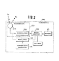
- Fig. 3 shows the circuit structure of the transmitter 100.
- a microprocessor 106 is connected to the antenna 104 via a demodulator 108 which demodulates the received demand signal SD, and to the battery 304 via the battery checker 300 to receive power therefrom.
- the microprocessor 106 includes a memory 110 storing the preset code.
- the microprocessor 106 reads out the preset code to a modulator 112.
- the modulator 112 is, in turn, connected to a carrier-wave generator 114 to receive a carrier wave.
- the modulator ll2 modulates the carrier-wave with the code-indicative signal from the microprocessor 106 to produce the final code signal SC.
- the antenna 104 of the transmitter 100 is built into the transmitter circuit board or on the surface of the transmitter casing 116 (shown in Fig. 2).
- the casing 116 is the size of a name card and thin enough to carry in a shirt pocket.
- Fig. 4 shows the circuitry of the controller 200.
- the shown embodiment of the keyless entry system is adapted to operate the door locks, the trunk lid lock, the starter motor and the steering lock device.
- the shown embodiment is adapted to control operation of the locks for the right- and left-side doors independently.
- manual switches 210-DR, 210-DL, 210-TL, 210-GL and 210-ST are provided on the vehicle body somewhere nearby the devices to be operated.
- the manual switches 210-DR and 210-DL are provided adjacent the door handles of respectively corresponding side soors.
- the manual switch 210-TL to operate the trunk lid lock device would be placed adjacent the trunk lid.
- Each manual switch is operable independently to operate the corresponding lock device. For example, when the manual switch 210-DR is depressed, the right-side door lock 220-DR is actuated to either to the locked or unlocked state.
- Each manual switch 210-DR, 210-DL, 210-TL, 210-SM and 210-ST is connected to a timer 222-DR, 222-DL, 222-TL, 222-SM and 222-ST through a normally closed relay 224-DR, 224-DL, 224-TL, 224-SM and 224-ST.
- the timers which will be referred to generically with reference numeral "222”, are responsive to depression of the corresponding manual switch, which will be referred to generically with reference numeral "210", to produce a HIGH-level timer signal St for a given period of time.
- the timer signal St is fed to a corresponding AND-gate 226-DR,. 226-DL, 226-TL, 226-SM and 226-ST, which will be referred to generically with reference numeral "226".
- the timer signal St is fed to a corresponding switching circuit 228-DR, 228-DL, 228-TL, 228-SM and 228-ST, which will be referred to generically with reference numeral "228".
- the switching circuit 228 closes in response to the timer signal St to connect the corresponding antenna 214-DR, 214-DL, 214-TL, 214-SM or 214-ST, which will be referred to generically with reference numeral "214", to a demodulator 230, whereby the code signal SC received by the corresponding antenna 214 is conducted to the demodulator.
- the timers 222 are also all connected to a microprocessor 232 via a multi- input OR gate 234.
- the microprocessor 232 includes a memory 236 which stores the preset code corresponding to that stored in the transmitter 100.
- the microprocessor 232 responds to the timer signal St received via the OR gate 234 by outputting the demand signal SD to the transmitter through a modulator 238 and antenna 214.
- the modulator 238 is connected to the antennae 214 via the switching circuits 228 to transmit the demand signal SD to the transmitter 100.
- the microprocessor 232 receives the code signal SC via the antenna 214 and the demodulator 230 and compares the received code with the stored code. When the received code matches the stored code, the microprocessor 232 outputs the control signal SL to the other input terminal of the AND gate 226 corresponding to the depressed manual switch.
- AND gate 226 transmits a HIGH-level signal to the driver signal generator 204- DR , 204- DL , 204-TL, 204-SM or 204-ST, which will be referred to generically with reference numeral "204".
- the driver signal generator 204 responds to the HIGH-level signal by outputting a driver signal to the corresponding actuator 202-DR, 202-DL, 202-TL, 202-SM or 202-ST of the lock 220-DR, 220-DL, 220-TL, 220-SM or 220-ST.
- the door locks 220-DR and 220-DL are connected to right- and left-side door lock switches 221-DR and 221-DL which turns ON when corresponding door lock is in locking state.
- the door lock switches 221-DR and 221-DL are connected to the microprocessor 232 to feed HIGH level door locking state indicative signals.
- the vehicle devices 220 also allows operations in a conventional mechanical key. When the mechanical key is used, the vehicle devices are operated independently of the keyless entry system.
- the microprocessor 106 of the transmitter 10D repeatedly executes the first control program illustrated in Fig. 5(A).
- the microprocessor 106 checks for receipt of the demand signal SD from the controller at a step 1002.
- the step 1002 is repeated until the demand signal SD is received.
- the transmitter 100 normally remains in a stand-by state, waiting to produce the code signal SC in response to the demand signal SD.
- the preset code C1 is read from the memory 110 at a step 1004.
- the microprocessor 106 then outputs the code-indicative signal to the modulator 112 which in turn outputs the code signal SC in step 106. Control then returns to the stand-by step 1002.
- the code signal SC is transmitted from the modulator to the controller for a given period of time and terminates when the given period of time expires.
- the given period of time during which the code signal SC is transmitted is so chosen that the controller 200 can activate the actuator 202 designated by the operated manual switch before expiration of that period.
- the code stored in the memory 110 is preferably a binary code, such as an 8-bit serial datum. This binary code rides on the carrier wave as modulated by the modulator to form the code signal SC.
- the microprocessor 232 is programmed to sample the amplitude of the received code signal at a first timing upon initial receipt of the code signal and at a second timing a given period of time after the first timing.
- the microprocessor 232 derives the differences between the amplitudes of the received signals at the first and second timings.
- the derived amplitude difference is compared with the reference value representing the expected code signal amplitude reduction in cases where the transmitter 100 is not locked in the vehicle. If the difference is less than the reference value, the microprocessor 232 outputs an alarm signal to the alarm device 306 to activate the latter.
- FIG. 5(A) summarizes the first control program executed by the microprocessor 106 in the transmitter 100
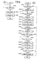
- FIG. 5(B) summarizes the second control program executed by the microprocessor 232 of the controller 200.
- Fig. 5(B) is a flowchart of a program executed concurrently and independently of the that illustrated in Fig. 5(A).
- initial step 2002 the output of OR-gate 234 is checked if any of the manual switches 210 have been depressed. If not, the program ends and is repeated again from the beginning. If one or more of the manual switches 210 has been closed, control passes to step 2004 wherein the demand signal S D is broadcast for reception by the transmitter 100. Thereafter, the microprocessor 232 waits at step 2006 for receipt of the code signal S from transmitter 100.
- Upon receipt of code signal S C' its amplitude S 1 is recorded in step 2008 for later use and then a read-time counter or timer is reset and started in step 2010.
- the timer clocks a predetermined period of time which is long enough for the signal level from a slowly receding transmitter to diminish noticeable, but not so long as to allow a walking driver to leave sight or earshot of the vehicle and its alarm device 306.
- the demodulator 230 and microprocessor 232 extract the coded information from the code signal S D in step 2012.
- the analogous code information is then retrieved from memory 236 in step 2014 for verification of the received code. if the received code matches the stored code when checked in subsequent step 2016, then the vehicle device associated with the particular manual switch closed in step 2002 is actuated in step 2018. An incorrect code match at step 2016 causes the current cycle of program execution to end.
- step 2010 is directly concerned with checking for a transmitter left in the passenger compartment by a foretful driver.
- the program were to end here, bypassing the subsequent steps 2022-2032, the keyless entry system could still function satisfactorily, although without the alarm feature described later. This would actually be preferrable in cases where only the glove box, trunk, starter, or the like are being used, as in such cases there is no chance of the driver leaving without the transmitter and an alarm to that effect would only be a niusance.
- step 2020 following actuation step 2018 the door switch positions are checked to check if all of the doors are checked.
- step 2022 et seq., as this is the only instance in which an alarm might be useful.
- step 2022 et seq.
- step 2022 the microprocessor 232 waits for the timer activated in step 2010 to count out the predetermined period of time. After this period has elapsed, the demand signal S D is again transmitted in step 2024 to elicit the code signal S c from transmitter 100.
- the amplitude S 2 of the received code signal is again sampled in step 2026, and this value is subtracted from or divided into the signal amplitude value S 2 recorded earlier to obtain an amplitude change value AS in step 2028.
- the amplitude change value AS is then compared in step 2030 to a reference amplitude change value ⁇ S ref which represents a minimal expectable drop in the signal level of the code signal S c if the transmitter 100 were being carried away from the vehicle. If the detected change AS matches or exceeds the predetermined threshold value ⁇ S ref' then it can be assumed that the driver has taken the transmitter with him or her, and the program ends without further operation. Otherwise an alarm is produced in step 2032 to warn the driver of his impending mistake.
- the predetermined period of time spent predominantly at step 2022 needs to be selected suitably, but that this can be done with confidence. Specifically, since the transmitter 100 will be quite close to the antennas 214 when the manual switch 210 is first depressed and the transmitted signal level will drop off with the square of the distance from the vehicle thereafter, a significant amplitude drop should be resolvable after only a short time.
- transmission of the demand signal SD and the code signal SC is performed by electromagnetic induction. Since locking and unlocking operations of the lock devices will generally be performed only when the transmitter is near the controller, good communication between the transmitter and the controller can be obtained by electromagnetic induction without significant power consumption.
- the manual switch 210-DR is depressed.
- the timer 222-DR becomes active to output the timer signal St.
- the timer signal St is applied to the AND gate 226DR and to the switching circuit 228-DR, the latter of which then closes to connect the antenna 214-DR to the microprocessor 232.
- the timer signal St from the timer 222-DR is also input to the microprocessor 232 via the OR gate 234.
- the microprocessor 232 responds inputs from the OR gate 234 by activating the modulator 238 to transmit the demand signal SD via the antenna 214-DR.
- the demand signal SD transmitted via the antenna 214-DR is received by the antenna 104 of the transmitter 100. Then, the demand signal SD is demodulated by the demodulator 108 to remove the carrier-wave components.
- the microprocessor 106 of the transmitter 100 then executes the steps 1004 and 1006 of the first control program of Fig. 5 (A) and outputs the code-indicative signal to the modulator 112.
- the modulator 112 thus transmits the code signal SC to the controller 200 via the antenna 104.
- the code signal SC is received by the antenna 214-DR and fed to the demodulator 230.
- the demodulator 230 demodulates the code signal SC to remove the carrier-wave components.
- the microprocessor 232 receives the demodulated code signal SC and executes the steps 2008 to 2016 of the second control program.
- the microprocessor 232 feeds the control signal SL to the AND gate 226-DR.
- the AND gate passes a HIGH-level signal to the driver signal generator 204-DR which produces the driver signal.
- the driver signal is applied to the actuator 202-DR of the right-side door lock device 220-DR to reverse the lock position. Since the right-side door lock device 220-DR was originally locked, it becomes unlocked upon activation of the actuator 202-DR.
- the antenna 214-DL sends the code signal SC to the microprocessor. If the input code matches the preset code, the AND gate 226-DL opens to activate the driver signal generator 204-DL. Thus, if the left-side door lock device is originally unlocked, it becomes locked.
- the timer 222-TL When the manual switch 210-TL is operated, the timer 222-TL become active to send a timer signal St to the AND gate 226-TL and the switching circuit 228-TL.
- the switching circuit 228-TL then closes to establish electrical communication between the antenna 214-TL and the demodulator 230 and the modulator 238.
- the code signal SC is transmitted from the transmitter 100 to the antenna 214-TL in response to the demand signal SD. If the input code is the same as the preset code, then the AND gate 226-TL opens to activate the driver signal generator 204-TL. Therefore, the trunk lid lock device 220-TL switches from its current position to the other position.
- the timer 222-GL When the manual switch 210-GL is operated to open the glove box lid, the timer 222-GL is activated to output the timer signal St. In response to the timer signal St, the switching circuit 228-GL establishes electrical communication between the antenna 214-GL and the demodulator 230. The code signal SC transmitted from the transmitter 100 is thus demodulated by the demodulator and input to the microprocessor 232.
- the AND gate 226-GL opens in response to the control signal SL from the microprocessor 232 to activate the driver signal generator 204-GL by the gate signal thereof.
- the actuator 202-GL In response to the driver signal from the driver signal generator 204-GL, the actuator 202-GL become active to reverse the position of the glove box lid lock from locked state to the unlocked state to allow access to the glove box.
- the manual switch 210-ST In order to release the steering wheel from the locked state, the manual switch 210-ST is depressed.
- the timer 222-ST becomes active to output the timer signal St for the given period of time.
- the antenna 214-ST. is connected to the microprocessor 232 via the demodulator 230 to receive the code signal SC from the transmitter 100.
- the driver signal generator 204-ST outputs the driver signal to reverse the position of the steering lock device 220-ST from the locked state to the unlocked state.
- Fig. 6 is a flowchart of a modified version of the program illustrated in Fig. 5(B), from which it differs only by the inclusion of steps 2017 and 2034-2040. These added steps enhance the alarm feature of Fig. 5(B) by locking up the keyless entry system tn cases where an alarm is produced in step 2032 but not heeded, so that the transmitter 100 remains locked inside the vehicle. This lock-up feature prevents unauthorized entry via the manual switches 210, forcing the vehicle user to re-enter the vehicle by means of conventional mechanical keys after forgetting the transmitter.
- Step 2017 is inserted between steps 2016 and 2018 and serves to prevent actuation of any vehicle devices by means of the keyless entry system in cases of lock-up. Specifically, a lock-up flag F is checked at step 2017 and if set, the program ends rather than proceeding to step 2018. The flag F L is normally reset, allowing normal program flow from step 2016 to step 2018, and can only be set in step 2040 described below.
- Step 2034 follows step 2032. After the alarm is produced, the timer is restarted in step 2034 to clock a second predetermined period of time allowed for the driver to re-enter the vehicle and retrieve the transmitter. In subsequent step 2036, the timer value is checked to see if the second period has expired. During the second period, control passes from step 2036 to step 2038, in which the output of OR-gate 234 is again checked to see if any manual switches are being operated. If so, the current program cycle ends; otherwise, control returns to step 2036. After the second period has expired without actuation of any of the manual switches 210, control passes from step 2036 to step 2040, in which lock-up flag F L is set. Thereafter, the program ends and step 2017 takes effect, locking up the keyless entry system.
- the vehicle devices i.e. door locks, trunk lid lock, and so forth, are operated by means of a mechanical key.
- Figs. 8 and 9 show modification of a manner of mounting the loop antennas 214 on the vehicle external surface.
- the antenna 214 is mounted along the door opening edge 214a of the vehicle body.
- the antenna 214 is mounted along the door window frame 214b of the door 214c.
- the antenna can be mounted various portion of the vehicle body, which portions are stable and cannot move.
- the antenna 214-TL for operating the trunk lid lock device may be provided on the rear windshield or the edge of rear windshield opening.
- antennas 214-ST and 214-SM for steering lock device and the starter motor may be mounted on the front windshield or along the edge of the front windshield opening.
- the user is now free of the responsibility of memorizing the preset code and need only depress a manual switch corresponding to the desired lock device to be operated.
- locking the transmitter in the vehicle can be successfully prevented by producing an alarm when the code signal level is remains substantially unchanged.
Abstract
Description
- The present invention relates generally to a unique and novel keyless entry system for operating automotive devices, such as door locks, a trunk lid lock, a glove box lid lock, steering lock devices and/or a starter motor without mechanical keys. More specifically, the invention relates to a keyless entry system which comprises a wireless transmitter transmitting a preset code to a controller which actuates the automotive devices when the code from the transmitter matches a preset code stored in the controller. Additionally, the invention relates to an alarm or cautioning means associated with the keyless entry system for producing an alarm or a caution when a user leaves the transmitter in the passenger compartment and starts to leave the vehicle.
- U.S. Patent 4,205,325, to Haygood et al, discloses a keyless entry system for an automotive vehicle permitting a plurality of operations to be achieved _from outside the vehicle by one who is knowledgeable of predetermined digital codes. Functions such as unlocking the doors of the vehicle, opening the rear trunk lid, opening a roof window, lowering the windows or programming the system with a user-preferred digital access code can all be performed by proper sequential operation of a digital keyboard mounted on the outside of the vehicle.
- This and other conventional keyless entry systems require the user to accurately input the predetermined code through the keyboard. Although such keyless entry systems have been well developed and considered useful for eliminating the need for mechanical keys, a serious problem may occur when the user of the vehicle forgets the predetermined code. If the user is outside of the vehicle and the vehicle door lock device is holding the doors locked, the user cannot unlock the door locks until he remembers the predetermined code.
- The present invention provides a novel and more useful system for operating the vehicle devices without an ignition key and without requiring manual entry of a predetermined code.
- Therefore, it is an principle object of the present invention to provide a unique and novel keyless entry system which requires no mechanical key operations or manual entry of a preset code.
- Another and more specific object of the present invention is to provide a keyless entry system including an electronic controller which actuates an automotive device in response to a preset code-indicative signal transmitted by a wireless signal transmitter.
- A further object of the present invention is to provide an alarm or caution system which notifies the vehicle user of cases where the transmitter remains inside the passenger compartment while the user is preparing-to leave the vehicle.
- In order to accomplish the aforementioned and other objects, a keyless entry system, in accordance with the present invention, generally comprises a wireless code transmitter which is portable by hand or in pockets and has an enclosed battery acting as a power source, and a controller connected to vehicle devices to electrically operate the latter in response to a preset code transmitted from the transmitter. The transmitter transmits a code signal to the controller when one of the vehicle devices is to be operated. The controller is responsive to the code signal when the transmitted code matches a preset code to produce a driver signal which actuates the designated vehicle device.
- In the preferred structure, a switch which activates the transmitter is provided on the external surface of the vehicle body and connected to the controller. When the switch is thrown, the controller transmits a demand signal to the transmitter possessed by the user. The transmitter responds to the demand signal by transmitting the code signal to the controller.
- Another and important feature of the invention is to provide a caution system which detects when the transmitter is locked in the vehicle, and produces an alarm in such cases.
- In the preferred construction, the locking transmitter in the vehicle caution means monitors the amplitude of the signal receiver from the transmitter and produces an alarm when the signal level remains within a given range for a given period of time. The given period of time should be selected to be long enough for the user to walk a certain distance away from the vehicle but short enough to produce the alarm before the user goes too far away to recognize the caution.
- According to one aspect of the invention, a keyless entry system for operting an automotive vehicle device without a mechanical key comprises an electrical actuator associated with the lock device and responsive a control signal to reverse the position of the lock device, a manual switch manually, a transmitter activated by manual operation of the manual switch to output a radio signal indicative of a unique code which identifies the transmitter, a battery for supplying electric power to the transmitter, a controller for receiving the radio signal from the transmitter, comparing the unique code indicated by the radio signal with a preset code, and producing the control signal when the unique code matches the preset code, and a transmitter-locking alarm means, associated with the controller, for detecting when the transmitter is locked in the vehicle and producing an alarm in such cases.
- according to another aspect of the invention, a keyless entry system for an automotive vehicle for operating one of a plurality of vehicle devices including a door lock device which is selective operated to either of a first locked position and a second unlocked position, comprises a plurality of electrical actuators respectively associated with the corresponding vehicle devices and responsive a control signal to operate the corresponding vehicle device to desired position, a plurality of manual switches, each adapted to be operated for operating one of the corresponding vehicle devices, a transmitter activated by manual operation of one of the manual switches to output a radio signal indicative of a unique code which identifies the transmitter, a controller for receiving the radio signal from the transmitter, comparing the unique code indicated by the radio signal with a preset code, and producing the control signal when the unique code matches the preset code, the controller including means responsive to manual operation of one of the manual switch for identifying one of the actuators to be operated and operating the identified- actuator for operating one of the vehicle devices corresponding to the manual switch operated, and a transmitter-locking alarm means, associated with the controller, for detecting when said transmitter is locked r in the vehicle and producing an alarm in such cases.
- The present invention will be understood more fully from the detailed description given below and from the accompanying drawings of the preferred embodiment of the present invention, which, however, should not be assumed to limit the invention to the specific embodiments but are for explanation and understanding only.
- In the drawings:
- Fig. 1 is a schematic block diagram showing the general concepts of a keyless entry system for an automotive vehicle device according to the present invention;
- Fig. 2 is a perspective view of an automotive vehicle to which the keyless entry system according to the present invention is applied;
- Fig. 3 is a block diagram of a transmitter in the preferred embodiment of a keyless entry system according to the present invention;
- Fig. 4 is a block diagram of a controller in the preferred embodiment of the keyless entry system according to the present invention;
- Figs. 5(A) and 5(B) are flowcharts of the operation of the transmitter and the controller, respectively; and
- Figs. 6(A) and 6(B) are flowcharts showing a modified mode of operation of the transmitter and the controller, respectively.
- Referring now to the drawings, particularly to Figs. 1 and 2, the preferred embodiment of a keyless entry system for an automotive vehicle according to the present invention generally comprises a
code transmitter 100 and acontroller 200. Thecontroller 200 is connected via adriver signal generator 204 toactuators 202 for vehicle devices such as door lock device, a trunk lid lock device, a starter motor and a steering lock device. - The
controller 200 includes a demandsignal SD generator 208 which sends a demand signal SD to thetransmitter 100 to activate the latter. The demandsignal SD generator 208 is connected to one or moremanual switches 210 which are placed on the external surface of the vehicle so as to be accessible from outside the vehicle. The demandsignal SD generator 208 produces a demand signal SD when one of themanual switches 210 is depressed. - As shown in Fig. 3, the
transmitter 100 includes areceiver circuit 102 for receiving the demand signal SD from the controller. Thetransmitter 100 becomes active when thereceiving circuit 102 receives the demand signal SD to produce a code signal SC which is indicative of a preset specific code. The preset code of theportable transmitter 100 differs from that of the demandsignal SD generator 208 so that thecontroller 200 can recognize when thetransmitter 100 is responding. - As shown in Fig. 3, the
transmitter 100 encloses a thin, compact, long-life battery 304, such as a mercury battery, acting as a power source. Thebattery 304 is connected to a transmitter circuit to supply electric power. - The
transmitter 100 continuously transmits the code signal SC to the controller for as long as it remains active. The code signal SC is received by areceiver 212 in thecontroller 200. Thecontroller 200 has acomparator 213 to compare the received code with a specific preset code. When the received code matches the code preset as compared in the comparator 215, thecontroller 200 sends a control signal SL to thedriver circuit generator 204. Thedriver signal generator 204 in turn sends a drive signal to one of theactuators 202 corresponding to themanual switch 210 operated. Theactuator 202 in activated by the driver signal from thedriver signal generator 204 to operate the corresponding vehicle device. - The
receiver 212 of thecontroller 200 is connected to asignal level detector 302 of a transmitter-locking alarm system 300. Thesignal level detector 302 monitors the amplitude of the code signal SC from thetransmitter 100 and produces a signal-level- indicative signal having a value which varies in proportion to the amplitude of the code signal. A signallevel variation detector 304 is associated with thesignal level detector 302 to detect the degree of change in the signal level within a given period of time. The signal level variation detector compares a detected signal level variation value with a reference value which is indicative of the expected reduction in the amplitude of the code signal within the given period as the user carries the transmitter away from the vehicle. The signallevel variation detector 304 produces an alarm signal when the magnitude of the signal level variation is less than the reference value. The alarm signal produced by the signallevel variation detector 304 is fed to analarm device 306 which then produces an alarm or a caution to notify the user that thetransmitter 100 is still locked in the vehicle. - Since the door lock device can be operated by depressing the
manual switch 210 which causes transmission of demand signal from thecontroller 200 to the transmitter placed inside of the vehicle and of code signal from the transmitter to the controller, the user can easily remove thetransmitter 100 from the passenger compartment even if thetransmitter 100 should be inadvertently locked in the vehicle. - It should be appreciated that, since the vehicle devices to be operated by the first embodiment of the keyless entry system are two-state locking devices for locking and unlocking vehicle doors, the trunk lid and the steering column and two-state starter motor, the
actuators 202 actuate the vehicle devices from the current position to the opposite position in response to the driver signal. For instance, when the vehicle device is in the locked position, the actuator unlocks the vehicle device in response to the driver signal. On the other hand, when the driver signal is sent to the actuator of a vehicle device which currently unlocked, that vehicle device is then locked. - The
transmitter 100 includes a transmitter/receiver antenna 104. In addition, aloop antenna 214 is built into one of thewindows 216 of the vehicle. Theloop antenna 214 transmits the demand signal SD to and receives the code signal SC from thetransmitter 100. As shown in Fig. 2, themanual switches 210 are mounted on anescutcheon 218 of an outside door handle for operation from outside the vehicle. - On the other hand, when the vehicle device is the starter motor which is normally off, the actuator turns the starter motor on for the period of time wherein the driver signal is applied thereto. Therefore, the starter motor is operated for the predetermined period of time in which the driver signal remains HIGH.
- The
transmitter 100 is housed in a case small enough to hand-carry or to pocket. - Fig. 3 shows the circuit structure of the
transmitter 100. Amicroprocessor 106 is connected to theantenna 104 via ademodulator 108 which demodulates the received demand signal SD, and to thebattery 304 via thebattery checker 300 to receive power therefrom. Themicroprocessor 106 includes amemory 110 storing the preset code. In response to the demand signal SD, themicroprocessor 106 reads out the preset code to amodulator 112. Themodulator 112 is, in turn, connected to a carrier-wave generator 114 to receive a carrier wave. The modulator ll2 modulates the carrier-wave with the code-indicative signal from themicroprocessor 106 to produce the final code signal SC. - In the preferred embodiment, the
antenna 104 of thetransmitter 100 is built into the transmitter circuit board or on the surface of the transmitter casing 116 (shown in Fig. 2). The casing 116 is the size of a name card and thin enough to carry in a shirt pocket. - Fig. 4 shows the circuitry of the
controller 200. As set forth above, the shown embodiment of the keyless entry system is adapted to operate the door locks, the trunk lid lock, the starter motor and the steering lock device. In addition, the shown embodiment is adapted to control operation of the locks for the right- and left-side doors independently. In order to allow independent operation of the lock devices, manual switches 210-DR, 210-DL, 210-TL, 210-GL and 210-ST are provided on the vehicle body somewhere nearby the devices to be operated. For example, the manual switches 210-DR and 210-DL are provided adjacent the door handles of respectively corresponding side soors. Similarly, the manual switch 210-TL to operate the trunk lid lock device would be placed adjacent the trunk lid. - Though the specific embodiment has been illustrated to locate respective manual switches adjacent the corresponding vehicle devices to be operated, it would be possible to provide all of manual switched in concentric manner on the outside
door handle escutcheon 218, for example. - Each manual switch is operable independently to operate the corresponding lock device. For example, when the manual switch 210-DR is depressed, the right-side door lock 220-DR is actuated to either to the locked or unlocked state.
- Each manual switch 210-DR, 210-DL, 210-TL, 210-SM and 210-ST is connected to a timer 222-DR, 222-DL, 222-TL, 222-SM and 222-ST through a normally closed relay 224-DR, 224-DL, 224-TL, 224-SM and 224-ST. The timers, which will be referred to generically with reference numeral "222", are responsive to depression of the corresponding manual switch, which will be referred to generically with reference numeral "210", to produce a HIGH-level timer signal St for a given period of time. This given period of time should be long enough to cover the time required to transmit the demand signal SD from the controller to the
transmitter 100 and to receive the code signal SC from the transmitter in return. The timer signal St is fed to a corresponding AND-gate 226-DR,. 226-DL, 226-TL, 226-SM and 226-ST, which will be referred to generically with reference numeral "226". At the same time, the timer signal St is fed to a corresponding switching circuit 228-DR, 228-DL, 228-TL, 228-SM and 228-ST, which will be referred to generically with reference numeral "228". Theswitching circuit 228 closes in response to the timer signal St to connect the corresponding antenna 214-DR, 214-DL, 214-TL, 214-SM or 214-ST, which will be referred to generically with reference numeral "214", to ademodulator 230, whereby the code signal SC received by the correspondingantenna 214 is conducted to the demodulator. Thetimers 222 are also all connected to amicroprocessor 232 via a multi- input ORgate 234. Themicroprocessor 232 includes amemory 236 which stores the preset code corresponding to that stored in thetransmitter 100. - The
microprocessor 232 responds to the timer signal St received via theOR gate 234 by outputting the demand signal SD to the transmitter through amodulator 238 andantenna 214. Themodulator 238 is connected to theantennae 214 via the switchingcircuits 228 to transmit the demand signal SD to thetransmitter 100. Themicroprocessor 232 receives the code signal SC via theantenna 214 and thedemodulator 230 and compares the received code with the stored code. When the received code matches the stored code, themicroprocessor 232 outputs the control signal SL to the other input terminal of the ANDgate 226 corresponding to the depressed manual switch. Therefore, at this time, ANDgate 226 transmits a HIGH-level signal to the driver signal generator 204-DR, 204-DL, 204-TL, 204-SM or 204-ST, which will be referred to generically with reference numeral "204". Thedriver signal generator 204 responds to the HIGH-level signal by outputting a driver signal to the corresponding actuator 202-DR, 202-DL, 202-TL, 202-SM or 202-ST of the lock 220-DR, 220-DL, 220-TL, 220-SM or 220-ST. - The door locks 220-DR and 220-DL are connected to right- and left-side door lock switches 221-DR and 221-DL which turns ON when corresponding door lock is in locking state. The door lock switches 221-DR and 221-DL are connected to the
microprocessor 232 to feed HIGH level door locking state indicative signals. - The
vehicle devices 220 also allows operations in a conventional mechanical key. When the mechanical key is used, the vehicle devices are operated independently of the keyless entry system. - The
microprocessor 106 of the transmitter 10D repeatedly executes the first control program illustrated in Fig. 5(A). In the first control program, themicroprocessor 106 checks for receipt of the demand signal SD from the controller at astep 1002. Thestep 1002 is repeated until the demand signal SD is received. In other words, thetransmitter 100 normally remains in a stand-by state, waiting to produce the code signal SC in response to the demand signal SD. - When the demand signal SD is detected at the
step 1002, the preset code C1 is read from thememory 110 at astep 1004. Themicroprocessor 106 then outputs the code-indicative signal to themodulator 112 which in turn outputs the code signal SC instep 106. Control then returns to the stand-by step 1002. - It should be noted that the code signal SC is transmitted from the modulator to the controller for a given period of time and terminates when the given period of time expires. The given period of time during which the code signal SC is transmitted is so chosen that the
controller 200 can activate theactuator 202 designated by the operated manual switch before expiration of that period. In addition, the code stored in thememory 110 is preferably a binary code, such as an 8-bit serial datum. This binary code rides on the carrier wave as modulated by the modulator to form the code signal SC. - The
microprocessor 232 is programmed to sample the amplitude of the received code signal at a first timing upon initial receipt of the code signal and at a second timing a given period of time after the first timing. Themicroprocessor 232 derives the differences between the amplitudes of the received signals at the first and second timings. The derived amplitude difference is compared with the reference value representing the expected code signal amplitude reduction in cases where thetransmitter 100 is not locked in the vehicle. If the difference is less than the reference value, themicroprocessor 232 outputs an alarm signal to thealarm device 306 to activate the latter. - The operation of the microprocessors in the
transmitter 100 and thecontroller 200 will be described in more detail with reference to flowcharts of control programs executed thereby. The flowchart of Fig. 5(A) summarizes the first control program executed by themicroprocessor 106 in thetransmitter 100 and the flowchart of Fig. 5(B) summarizes the second control program executed by themicroprocessor 232 of thecontroller 200. - Fig. 5(B) is a flowchart of a program executed concurrently and independently of the that illustrated in Fig. 5(A). In
initial step 2002, the output ofOR-gate 234 is checked if any of themanual switches 210 have been depressed. If not, the program ends and is repeated again from the beginning. If one or more of themanual switches 210 has been closed, control passes to step 2004 wherein the demand signal SD is broadcast for reception by thetransmitter 100. Thereafter, themicroprocessor 232 waits atstep 2006 for receipt of the code signal S fromtransmitter 100. Upon receipt of code signal SC' its amplitude S1 is recorded instep 2008 for later use and then a read-time counter or timer is reset and started instep 2010. In this embodiment, the timer clocks a predetermined period of time which is long enough for the signal level from a slowly receding transmitter to diminish noticeable, but not so long as to allow a walking driver to leave sight or earshot of the vehicle and itsalarm device 306. - Following
step 2010, thedemodulator 230 andmicroprocessor 232 extract the coded information from the code signal SD instep 2012. The analogous code information is then retrieved frommemory 236 instep 2014 for verification of the received code. if the received code matches the stored code when checked insubsequent step 2016, then the vehicle device associated with the particular manual switch closed instep 2002 is actuated instep 2018. An incorrect code match atstep 2016 causes the current cycle of program execution to end. - -Of the steps executed up to this point,
only step 2010 is directly concerned with checking for a transmitter left in the passenger compartment by a foretful driver. In fact, if the program were to end here, bypassing the subsequent steps 2022-2032, the keyless entry system could still function satisfactorily, although without the alarm feature described later. This would actually be preferrable in cases where only the glove box, trunk, starter, or the like are being used, as in such cases there is no chance of the driver leaving without the transmitter and an alarm to that effect would only be a niusance. Accordingly, instep 2020 followingactuation step 2018, the door switch positions are checked to check if all of the doors are checked. If it was the all of the doors being locked, the program continues to step 2022 et seq., as this is the only instance in which an alarm might be useful. Although which device is to be actuated and its state of actuation at any time are not easy to check in the circuit shown in Fig. 4, modern vehicles commonly have accessory safety systems which monitor door locks and the like, and such a system may be tapped to detect when the driver's door or other doors are being locked. Of course,step 2020 may be omitted altogether. - In
step 2022, themicroprocessor 232 waits for the timer activated instep 2010 to count out the predetermined period of time. After this period has elapsed, the demand signal SD is again transmitted instep 2024 to elicit the code signal Sc fromtransmitter 100. The amplitude S2 of the received code signal is again sampled instep 2026, and this value is subtracted from or divided into the signal amplitude value S2 recorded earlier to obtain an amplitude change value AS instep 2028. The amplitude change value AS is then compared instep 2030 to a reference amplitude change value ΔSref which represents a minimal expectable drop in the signal level of the code signal Sc if thetransmitter 100 were being carried away from the vehicle. If the detected change AS matches or exceeds the predetermined threshold value ΔSref' then it can be assumed that the driver has taken the transmitter with him or her, and the program ends without further operation. Otherwise an alarm is produced instep 2032 to warn the driver of his impending mistake. - It should be noted that the predetermined period of time spent predominantly at
step 2022 needs to be selected suitably, but that this can be done with confidence. Specifically, since thetransmitter 100 will be quite close to theantennas 214 when themanual switch 210 is first depressed and the transmitted signal level will drop off with the square of the distance from the vehicle thereafter, a significant amplitude drop should be resolvable after only a short time. - In the shown embodiment as set forth above, since the code signal SC is output only when the demand signal SD is input from the controller, consumption of electric power of the battery in the transmitter is significantly reduced in comparison with system which might employ constant transmission of the code signal SC. Thus, the life-time of the battery of the transmitter is prolonged even though electric power is constantly supplied to the microprocessor to hold same in stand-by. It should be appreciated that the electric power needed to power the microprocessor is substantially smaller than that consumed in transmitting the code signal SC. Therefore, constant power supply to the microprocessor will not significantly affect the life-time of the battery.
- Similarly, since the demand signal SD is produced only when at least one of the manual switches is depressed, consumption of the electric power by the controller is significantly limitted.
- _It is also to be noted that transmission of the demand signal SD and the code signal SC is performed by electromagnetic induction. Since locking and unlocking operations of the lock devices will generally be performed only when the transmitter is near the controller, good communication between the transmitter and the controller can be obtained by electromagnetic induction without significant power consumption.
- In order to unlock the right-side door lock device 220-DR, the manual switch 210-DR is depressed. When the
ignition switch 302 is in the OFF position, the timer 222-DR becomes active to output the timer signal St. The timer signal St is applied to the AND gate 226DR and to the switching circuit 228-DR, the latter of which then closes to connect the antenna 214-DR to themicroprocessor 232. - The timer signal St from the timer 222-DR is also input to the
microprocessor 232 via theOR gate 234. Themicroprocessor 232 responds inputs from theOR gate 234 by activating themodulator 238 to transmit the demand signal SD via the antenna 214-DR. - The demand signal SD transmitted via the antenna 214-DR is received by the
antenna 104 of thetransmitter 100. Then, the demand signal SD is demodulated by thedemodulator 108 to remove the carrier-wave components. Themicroprocessor 106 of thetransmitter 100 then executes thesteps modulator 112. Themodulator 112 thus transmits the code signal SC to thecontroller 200 via theantenna 104. - The code signal SC is received by the antenna 214-DR and fed to the
demodulator 230. Thedemodulator 230 demodulates the code signal SC to remove the carrier-wave components. Themicroprocessor 232 receives the demodulated code signal SC and executes thesteps 2008 to 2016 of the second control program. When the input code matches the preset code in thememory 236, themicroprocessor 232 feeds the control signal SL to the AND gate 226-DR. At this time, since the timer signal St is still being applied to one of the input terminals of the AND gate, the AND condition of the timer signal St and the control signal SL is established and as a result, the AND gate passes a HIGH-level signal to the driver signal generator 204-DR which produces the driver signal. The driver signal is applied to the actuator 202-DR of the right-side door lock device 220-DR to reverse the lock position. Since the right-side door lock device 220-DR was originally locked, it becomes unlocked upon activation of the actuator 202-DR. - Similarly, when the manual switch 210-DL is closed to operate the left-side door lock device, the antenna 214-DL sends the code signal SC to the microprocessor. If the input code matches the preset code, the AND gate 226-DL opens to activate the driver signal generator 204-DL. Thus, if the left-side door lock device is originally unlocked, it becomes locked.
- When the manual switch 210-TL is operated, the timer 222-TL become active to send a timer signal St to the AND gate 226-TL and the switching circuit 228-TL. The switching circuit 228-TL then closes to establish electrical communication between the antenna 214-TL and the
demodulator 230 and themodulator 238. The code signal SC is transmitted from thetransmitter 100 to the antenna 214-TL in response to the demand signal SD. If the input code is the same as the preset code, then the AND gate 226-TL opens to activate the driver signal generator 204-TL. Therefore, the trunk lid lock device 220-TL switches from its current position to the other position. - When the manual switch 210-GL is operated to open the glove box lid, the timer 222-GL is activated to output the timer signal St. In response to the timer signal St, the switching circuit 228-GL establishes electrical communication between the antenna 214-GL and the
demodulator 230. The code signal SC transmitted from thetransmitter 100 is thus demodulated by the demodulator and input to themicroprocessor 232. The AND gate 226-GL opens in response to the control signal SL from themicroprocessor 232 to activate the driver signal generator 204-GL by the gate signal thereof. In response to the driver signal from the driver signal generator 204-GL, the actuator 202-GL become active to reverse the position of the glove box lid lock from locked state to the unlocked state to allow access to the glove box. - In order to release the steering wheel from the locked state, the manual switch 210-ST is depressed. The timer 222-ST becomes active to output the timer signal St for the given period of time. During the period of time in which the timer 222-ST is active, the antenna 214-ST. is connected to the
microprocessor 232 via thedemodulator 230 to receive the code signal SC from thetransmitter 100. When the input code matches the preset code in thememory 236, the driver signal generator 204-ST outputs the driver signal to reverse the position of the steering lock device 220-ST from the locked state to the unlocked state. - Fig. 6 is a flowchart of a modified version of the program illustrated in Fig. 5(B), from which it differs only by the inclusion of
steps 2017 and 2034-2040. These added steps enhance the alarm feature of Fig. 5(B) by locking up the keyless entry system tn cases where an alarm is produced instep 2032 but not heeded, so that thetransmitter 100 remains locked inside the vehicle. This lock-up feature prevents unauthorized entry via themanual switches 210, forcing the vehicle user to re-enter the vehicle by means of conventional mechanical keys after forgetting the transmitter. - -
Step 2017 is inserted betweensteps step 2017 and if set, the program ends rather than proceeding to step 2018. The flag FL is normally reset, allowing normal program flow fromstep 2016 to step 2018, and can only be set instep 2040 described below. -
Step 2034 followsstep 2032. After the alarm is produced, the timer is restarted instep 2034 to clock a second predetermined period of time allowed for the driver to re-enter the vehicle and retrieve the transmitter. Insubsequent step 2036, the timer value is checked to see if the second period has expired. During the second period, control passes fromstep 2036 to step 2038, in which the output ofOR-gate 234 is again checked to see if any manual switches are being operated. If so, the current program cycle ends; otherwise, control returns to step 2036. After the second period has expired without actuation of any of themanual switches 210, control passes fromstep 2036 to step 2040, in which lock-up flag FL is set. Thereafter, the program ends andstep 2017 takes effect, locking up the keyless entry system. - When the keyless entry system is disabled as set forth above, the vehicle devices, i.e. door locks, trunk lid lock, and so forth, are operated by means of a mechanical key.
- Figs. 8 and 9 show modification of a manner of mounting the
loop antennas 214 on the vehicle external surface. According to the modification of Fig. 8, theantenna 214 is mounted along the door opening edge 214a of the vehicle body. On the other hand, in the modification of Fig. 9, theantenna 214 is mounted along the door window frame 214b of the door 214c. - By these modifications, wearing of the antenna by up and-down of the side window would be satisfactorily prevented. For operating a plurality of vehicle devices, the antenna can be mounted various portion of the vehicle body, which portions are stable and cannot move. For example, the antenna 214-TL for operating the trunk lid lock device may be provided on the rear windshield or the edge of rear windshield opening. Similarly, antennas 214-ST and 214-SM for steering lock device and the starter motor may be mounted on the front windshield or along the edge of the front windshield opening.
- As will be appreciated herefrom, according to the present invention, the user is now free of the responsibility of memorizing the preset code and need only depress a manual switch corresponding to the desired lock device to be operated. In addition, according to the present invention, locking the transmitter in the vehicle can be successfully prevented by producing an alarm when the code signal level is remains substantially unchanged.
- Therefore, the invention fulfills all of the objects and advantages sought therefor.
Claims (20)
Applications Claiming Priority (2)
| Application Number | Priority Date | Filing Date | Title |
|---|---|---|---|
| JP58172681A JPS6065875A (en) | 1983-09-19 | 1983-09-19 | Locking controller for vehicle |
| JP172681/83 | 1983-09-19 |
Publications (3)
| Publication Number | Publication Date |
|---|---|
| EP0140137A2 true EP0140137A2 (en) | 1985-05-08 |
| EP0140137A3 EP0140137A3 (en) | 1988-03-16 |
| EP0140137B1 EP0140137B1 (en) | 1991-10-30 |
Family
ID=15946387
Family Applications (1)
| Application Number | Title | Priority Date | Filing Date |
|---|---|---|---|
| EP84111197A Expired - Lifetime EP0140137B1 (en) | 1983-09-19 | 1984-09-19 | Keyless entry system for automotive devices with feature for giving caution for locking wireless code transmitter in vehicle |
Country Status (4)
| Country | Link |
|---|---|
| US (1) | US4670746A (en) |
| EP (1) | EP0140137B1 (en) |
| JP (1) | JPS6065875A (en) |
| DE (1) | DE3485224D1 (en) |
Cited By (6)
| Publication number | Priority date | Publication date | Assignee | Title |
|---|---|---|---|---|
| DE3712552A1 (en) * | 1986-04-14 | 1987-10-15 | Fuji Heavy Ind Ltd | CONTROL SYSTEM FOR THE DOOR LOCK OF A MOTOR VEHICLE |
| DE4123654A1 (en) * | 1991-07-17 | 1993-01-21 | Bayerische Motoren Werke Ag | METHOD FOR DETECTING A PORTABLE TRANSPONDER INCLUDED IN THE VEHICLE |
| DE4240426A1 (en) * | 1992-12-02 | 1994-06-09 | Thomas Schmitz | Ignition key protection system for centralised locking of motor vehicle - uses interrogation signal and detected response to unlock locked vehicle when ignition key is still inside |
| EP0628456A3 (en) * | 1993-05-28 | 1995-03-15 | Code Alarm | Vehicle security system. |
| DE4411435A1 (en) * | 1994-03-31 | 1995-10-05 | Bayerische Motoren Werke Ag | Method for controlling the use of a motor vehicle using a two-part code signal |
| US5841363A (en) * | 1993-10-01 | 1998-11-24 | Marquardt Gmbh | Locking system especially for automobiles |
Families Citing this family (94)
| Publication number | Priority date | Publication date | Assignee | Title |
|---|---|---|---|---|
| US4719460A (en) * | 1983-09-19 | 1988-01-12 | Nissan Motor Company, Limited | Keyless entry system for automotive vehicle devices with theft-prevention feature |
| JPS6064272A (en) * | 1983-09-19 | 1985-04-12 | Nissan Motor Co Ltd | Radio type on-vehicle load control apparatus |
| JPS60183246A (en) * | 1984-03-01 | 1985-09-18 | Nissan Motor Co Ltd | Unlocking control unit for vehicle |
| JPS61196080A (en) * | 1985-02-21 | 1986-08-30 | 日産自動車株式会社 | Wireless user discrimination apparatus |
| GB2177152B (en) * | 1985-07-04 | 1988-11-16 | Kokusan Kinzoku Kogyo Co Limit | Radio wave signal controlled lock arrangement |
| JPS6211360A (en) * | 1985-07-09 | 1987-01-20 | Alpine Electron Inc | Burglarproof method for automobile |
| US5335264A (en) * | 1985-07-09 | 1994-08-02 | Alpine Electronics, Inc. | Method and apparatus for monitoring sound within a vehicle by telephone |
| JPS6211359A (en) * | 1985-07-09 | 1987-01-20 | Alpine Electron Inc | Status discriminating method for burglarproof system |
| DE3624707A1 (en) * | 1985-07-22 | 1987-01-22 | Aisin Seiki | LOCK CONTROL DEVICE FOR VEHICLES |
| JPS6238035A (en) * | 1985-08-12 | 1987-02-19 | Nissan Motor Co Ltd | Thin plate type portable device |
| JPS6234092U (en) * | 1985-08-15 | 1987-02-28 | ||
| JPS6278379A (en) * | 1985-09-30 | 1987-04-10 | 日産自動車株式会社 | Locking and unlocking control apparatus for vehicle |
| DE3536378A1 (en) * | 1985-10-11 | 1987-04-16 | Bayerische Motoren Werke Ag | SAFETY DEVICE FOR A MOTOR VEHICLE |
| JPS62101769A (en) * | 1985-10-28 | 1987-05-12 | 国産金属工業株式会社 | Radiowave lock system of vehicle |
| JPS62121285A (en) * | 1985-11-21 | 1987-06-02 | 株式会社アルファ | Radio wave lock system of vehicle |
| JPS62101768A (en) * | 1985-10-28 | 1987-05-12 | 国産金属工業株式会社 | Radiowave lock system of vehicle |
| FR2589187B1 (en) * | 1986-04-10 | 1995-05-19 | Kokusan Kinzoku Kogyo Kk | LOCKING AND UNLOCKING SYSTEM FOR A CAR, CONTROLLED BY A RADIO SIGNAL |
| GB2194580B (en) * | 1986-04-10 | 1990-08-01 | Kokusan Kinzoku Kogyo Kk | Vehicle lock system |
| GB2191322B (en) * | 1986-04-23 | 1989-12-06 | Yushin Seiki Kogyo Kk | Remote control device for vehicle locks |
| JPH0625503B2 (en) * | 1986-06-20 | 1994-04-06 | 日産自動車株式会社 | Unlock control device |
| JPH0747910B2 (en) * | 1986-10-24 | 1995-05-24 | 日産自動車株式会社 | Remote control device |
| JP2546842B2 (en) * | 1987-06-16 | 1996-10-23 | 日産自動車株式会社 | Vehicle locking / unlocking control device |
| FI77550C (en) * | 1987-07-29 | 1989-03-10 | Nokia Mobira Oy | FOERFARANDE FOER SAMMANKOPPLING TILL ANVAENDARENS KORT VID EN MOBILRADIOTELEFON. |
| US5291193A (en) * | 1988-01-21 | 1994-03-01 | Matsushita Electric Works, Ltd. | Identification registration for a wireless transmission-reception control system |
| US4942393A (en) * | 1988-05-27 | 1990-07-17 | Lectron Products, Inc. | Passive keyless entry system |
| US5614885A (en) * | 1988-12-05 | 1997-03-25 | Prince Corporation | Electrical control system for vehicle options |
| US5475366A (en) * | 1988-12-05 | 1995-12-12 | Prince Corporation | Electrical control system for vehicle options |
| US5479155A (en) * | 1988-12-05 | 1995-12-26 | Prince Corporation | Vehicle accessory trainable transmitter |
| JP2525905B2 (en) * | 1989-10-12 | 1996-08-21 | アルパイン株式会社 | Security remote control device |
| US5113182B1 (en) * | 1990-01-19 | 1995-11-07 | Prince Corp | Vehicle door locking system detecting that all doors are closed |
| DE4005448A1 (en) * | 1990-02-21 | 1991-08-22 | Jaroschinsky Achim | Matching two personal data groups - selectively exchanging data via terminals which perform data group comparison |
| US5627529A (en) * | 1994-03-11 | 1997-05-06 | Prince Corporation | Vehicle control system with trainable transceiver |
| US5455716A (en) * | 1990-08-14 | 1995-10-03 | Prince Corporation | Vehicle mirror with electrical accessories |
| JP2877594B2 (en) * | 1991-11-14 | 1999-03-31 | 富士通株式会社 | Visitor management system |
| FR2697864B1 (en) * | 1992-11-06 | 1995-01-06 | Valeo Electronique | System for remotely controlling the locking and unlocking of the doors and openings of a passenger compartment, in particular of a motor vehicle. |
| FR2700625B1 (en) * | 1993-01-19 | 1995-02-17 | Renault | Method for locking a vehicle controlled by a radio signal and device for implementing it. |
| US5903226A (en) * | 1993-03-15 | 1999-05-11 | Prince Corporation | Trainable RF system for remotely controlling household appliances |
| US5528216A (en) * | 1993-08-23 | 1996-06-18 | Main; Louis | Vehicle anti-theft brake locking system |
| DE69428087T2 (en) * | 1993-10-08 | 2002-04-25 | Trw Inc | Receiver for use in a keyless entry system and for receiving public radio broadcasts |
| US5659291A (en) * | 1994-11-28 | 1997-08-19 | Ford Motor Company | Key-in-ignition lock reminder system |
| JP3250406B2 (en) * | 1995-03-13 | 2002-01-28 | 日産自動車株式会社 | Keyless entry device |
| US5736935A (en) * | 1995-03-14 | 1998-04-07 | Trw Inc. | Keyless vehicle entry and engine starting system |
| US7492905B2 (en) | 1995-05-17 | 2009-02-17 | The Chamberlain Group, Inc. | Rolling code security system |
| BR9606663A (en) * | 1995-05-17 | 1997-09-16 | Chamberlain Group Inc | Transmitter to send an encrypted signal to control a receiver actuator to receive an encrypted signal from a transmitter and to generate an actuation signal and receiver to receive an encrypted radio frequency signal from a transmitter and to generate an actuation signal |
| US6980655B2 (en) | 2000-01-21 | 2005-12-27 | The Chamberlain Group, Inc. | Rolling code security system |
| US6690796B1 (en) | 1995-05-17 | 2004-02-10 | The Chamberlain Group, Inc. | Rolling code security system |
| US5686903A (en) * | 1995-05-19 | 1997-11-11 | Prince Corporation | Trainable RF transceiver |
| US5699055A (en) * | 1995-05-19 | 1997-12-16 | Prince Corporation | Trainable transceiver and method for learning an activation signal that remotely actuates a device |
| US5699054A (en) * | 1995-05-19 | 1997-12-16 | Prince Corporation | Trainable transceiver including a dynamically tunable antenna |
| US5661804A (en) * | 1995-06-27 | 1997-08-26 | Prince Corporation | Trainable transceiver capable of learning variable codes |
| KR100378112B1 (en) * | 1995-07-25 | 2003-05-23 | 삼성전자주식회사 | Automatic locking/unlocking system using wireless communication and method for the same |
| US5777546A (en) * | 1996-02-08 | 1998-07-07 | Chrysler Corporation | Method of selection of deselection of automatic power door locks |
| JPH10159419A (en) * | 1996-11-29 | 1998-06-16 | Aisin Seiki Co Ltd | Auto-door-lock control device |
| DE19735658C1 (en) * | 1997-08-16 | 1998-07-30 | Bosch Gmbh Robert | Vehicle locking system using transponders inside |
| US5831520A (en) * | 1998-01-14 | 1998-11-03 | Ford Motor Company | Anti-lockout smart key system |
| US7106171B1 (en) | 1998-04-16 | 2006-09-12 | Burgess James P | Keyless command system for vehicles and other applications |
| US6031465A (en) * | 1998-04-16 | 2000-02-29 | Burgess; James P. | Keyless entry system for vehicles in particular |
| IL127569A0 (en) | 1998-09-16 | 1999-10-28 | Comsense Technologies Ltd | Interactive toys |
| DE19839350B4 (en) * | 1998-08-28 | 2005-06-30 | Daimlerchrysler Ag | vehicle locking |
| US6607136B1 (en) | 1998-09-16 | 2003-08-19 | Beepcard Inc. | Physical presence digital authentication system |
| CA2345745A1 (en) | 1998-10-02 | 2000-04-13 | Comsense Technologies, Ltd. | Card for interaction with a computer |
| US8019609B2 (en) | 1999-10-04 | 2011-09-13 | Dialware Inc. | Sonic/ultrasonic authentication method |
| US6617961B1 (en) | 1999-11-15 | 2003-09-09 | Strattec Security Corporation | Security system for a vehicle and method of operating same |
| KR20010059894A (en) * | 1999-12-30 | 2001-07-06 | 이계안 | Card-key type apparatus for locking and releasing door in auto mobile and method of the same |
| US9219708B2 (en) | 2001-03-22 | 2015-12-22 | DialwareInc. | Method and system for remotely authenticating identification devices |
| DE10160964B4 (en) * | 2001-12-12 | 2004-02-05 | Siemens Ag | Method and device for theft protection of motor vehicles |
| FR2838223B1 (en) * | 2002-04-09 | 2004-06-25 | Valeo Electronique | METHOD FOR CONTROLLING THE PRESENCE OF AN IDENTIFIER BADGE FOR A HANDS-FREE SYSTEM, PARTICULARLY FOR A MOTOR VEHICLE |
| US6906612B2 (en) * | 2002-04-11 | 2005-06-14 | Lear Corporation | System and method for vehicle passive entry having inside/outside detection |
| US7005960B2 (en) | 2002-06-13 | 2006-02-28 | Omega Patents, L.L.C. | Vehicle remote control system with selectable outputs and associated methods |
| JP3668729B2 (en) * | 2002-08-29 | 2005-07-06 | 三菱電機株式会社 | In-vehicle device remote control system |
| US6813916B2 (en) * | 2002-11-12 | 2004-11-09 | Ching-Wen Chang | Remote control lock structure |
| US8422667B2 (en) | 2005-01-27 | 2013-04-16 | The Chamberlain Group, Inc. | Method and apparatus to facilitate transmission of an encrypted rolling code |
| US9148409B2 (en) | 2005-06-30 | 2015-09-29 | The Chamberlain Group, Inc. | Method and apparatus to facilitate message transmission and reception using different transmission characteristics |
| JP4539448B2 (en) * | 2005-06-09 | 2010-09-08 | マツダ株式会社 | Smart entry system for vehicles |
| EP1731390B1 (en) * | 2005-06-09 | 2010-01-06 | Mazda Motor Corporation | A keyless entry system and method for a vehicle |
| US7609146B2 (en) * | 2005-07-27 | 2009-10-27 | Lear Corporation | System and method for controlling a function using a variable sensitivity receiver |
| JP4604984B2 (en) * | 2005-11-25 | 2011-01-05 | 株式会社デンソー | In-vehicle device control system |
| DE102006042976A1 (en) * | 2006-09-13 | 2008-04-03 | Siemens Ag | Access arrangement for a vehicle |
| US7850078B2 (en) * | 2007-04-23 | 2010-12-14 | Lear Corporation | Remote control reactivation |
| JP2010077614A (en) * | 2008-09-24 | 2010-04-08 | Tokai Rika Co Ltd | Electric locking/unlocking device for opening/closing body |
| JP2010215001A (en) * | 2009-03-13 | 2010-09-30 | Omron Corp | Communication device and communication method |
| DE102009050125A1 (en) * | 2009-10-21 | 2011-04-28 | Continental Automotive Gmbh | Electric energy storage with integrated deep discharge device |
| US20110140839A1 (en) * | 2009-12-11 | 2011-06-16 | Honda Motor Co., Ltd. | Method and system for disabling passive entry key located inside a vehicle |
| US8405606B2 (en) * | 2010-07-02 | 2013-03-26 | Alpha & Omega Inc. | Remote control systems and methods for activating buttons of digital electronic display devices |
| US8620490B2 (en) | 2011-04-25 | 2013-12-31 | Honda Motor Co., Ltd. | Method to disable trunk lockout protection for smart entry |
| DE102011121308A1 (en) * | 2011-12-15 | 2013-06-20 | Gm Global Technology Operations, Llc | Storage compartment arrangement for a motor vehicle with an adjustable storage compartment cover |
| KR101534702B1 (en) * | 2013-12-05 | 2015-07-07 | 현대자동차 주식회사 | Keyless entry system and control method for the same |
| US10042381B2 (en) | 2015-08-10 | 2018-08-07 | Open Up LLC | Double wireless receipt and transmission with mechanical movement causing second wireless transmission |
| CN109094519A (en) * | 2017-06-20 | 2018-12-28 | 宁波轩悦行电动汽车服务有限公司 | A kind of electric car car locking anti-interference system and method |
| US10934987B2 (en) * | 2017-11-24 | 2021-03-02 | Bezalel Hirsch | Remote starter adapter for use with a communication device |
| US10652743B2 (en) | 2017-12-21 | 2020-05-12 | The Chamberlain Group, Inc. | Security system for a moveable barrier operator |
| US11074773B1 (en) | 2018-06-27 | 2021-07-27 | The Chamberlain Group, Inc. | Network-based control of movable barrier operators for autonomous vehicles |
| CA3107457A1 (en) | 2018-08-01 | 2020-02-06 | The Chamberlain Group, Inc. | Movable barrier operator and transmitter pairing over a network |
| US10997810B2 (en) | 2019-05-16 | 2021-05-04 | The Chamberlain Group, Inc. | In-vehicle transmitter training |
Citations (5)
| Publication number | Priority date | Publication date | Assignee | Title |
|---|---|---|---|---|
| US3196440A (en) * | 1962-11-07 | 1965-07-20 | Commercial Factors Ltd | Radio control system for operating a distant electromechanical transducer door lock utilizing a capacity-sensitive circuit at the distant location and an operator-carried transceiver |
| US4223296A (en) * | 1978-12-01 | 1980-09-16 | Mujo Kim | Engine key reminder system for automobile |
| GB2051442A (en) * | 1979-03-30 | 1981-01-14 | Howard J A | A security system |
| EP0078962A2 (en) * | 1981-11-03 | 1983-05-18 | GEMINI ELETTRONICA s.r.l. | System for centralized control of a motor-vehicle accesses safety lock device, warning and antitheft installation and other relevant functions connection |
| EP0158354B1 (en) * | 1984-04-12 | 1988-12-28 | Nissan Motor Co., Ltd. | Keyless entry system for automotive devices with compact, portable wireles code transmitter, and feature for preventing users from locking transmitter in vehicle |
Family Cites Families (6)
| Publication number | Priority date | Publication date | Assignee | Title |
|---|---|---|---|---|
| US3723967A (en) * | 1971-03-24 | 1973-03-27 | Wagner Electric Corp | Induction-keyed door-lock and power control circuit for automotive vehicles and the like |
| BE791039A (en) * | 1971-11-08 | 1973-05-07 | Lewis Security Syst Ltd | SECURITY SYSTEMS |
| US3866168A (en) * | 1973-01-15 | 1975-02-11 | Wager Electric Corp | Door lock, power and alarm control circuit for automotive vehicles and the like |
| US4137985A (en) * | 1977-11-25 | 1979-02-06 | General Motors Corporation | Vehicle security system |
| US4205325A (en) * | 1977-12-27 | 1980-05-27 | Ford Motor Company | Keyless entry system |
| JPS55123538A (en) * | 1979-03-14 | 1980-09-24 | Mitsui Mining & Smelting Co Ltd | Locking-unlocking scanning indicating device for car door |
-
1983
- 1983-09-19 JP JP58172681A patent/JPS6065875A/en active Granted
-
1984
- 1984-09-18 US US06/651,785 patent/US4670746A/en not_active Expired - Lifetime
- 1984-09-19 EP EP84111197A patent/EP0140137B1/en not_active Expired - Lifetime
- 1984-09-19 DE DE8484111197T patent/DE3485224D1/en not_active Expired - Lifetime
Patent Citations (5)
| Publication number | Priority date | Publication date | Assignee | Title |
|---|---|---|---|---|
| US3196440A (en) * | 1962-11-07 | 1965-07-20 | Commercial Factors Ltd | Radio control system for operating a distant electromechanical transducer door lock utilizing a capacity-sensitive circuit at the distant location and an operator-carried transceiver |
| US4223296A (en) * | 1978-12-01 | 1980-09-16 | Mujo Kim | Engine key reminder system for automobile |
| GB2051442A (en) * | 1979-03-30 | 1981-01-14 | Howard J A | A security system |
| EP0078962A2 (en) * | 1981-11-03 | 1983-05-18 | GEMINI ELETTRONICA s.r.l. | System for centralized control of a motor-vehicle accesses safety lock device, warning and antitheft installation and other relevant functions connection |
| EP0158354B1 (en) * | 1984-04-12 | 1988-12-28 | Nissan Motor Co., Ltd. | Keyless entry system for automotive devices with compact, portable wireles code transmitter, and feature for preventing users from locking transmitter in vehicle |
Cited By (6)
| Publication number | Priority date | Publication date | Assignee | Title |
|---|---|---|---|---|
| DE3712552A1 (en) * | 1986-04-14 | 1987-10-15 | Fuji Heavy Ind Ltd | CONTROL SYSTEM FOR THE DOOR LOCK OF A MOTOR VEHICLE |
| DE4123654A1 (en) * | 1991-07-17 | 1993-01-21 | Bayerische Motoren Werke Ag | METHOD FOR DETECTING A PORTABLE TRANSPONDER INCLUDED IN THE VEHICLE |
| DE4240426A1 (en) * | 1992-12-02 | 1994-06-09 | Thomas Schmitz | Ignition key protection system for centralised locking of motor vehicle - uses interrogation signal and detected response to unlock locked vehicle when ignition key is still inside |
| EP0628456A3 (en) * | 1993-05-28 | 1995-03-15 | Code Alarm | Vehicle security system. |
| US5841363A (en) * | 1993-10-01 | 1998-11-24 | Marquardt Gmbh | Locking system especially for automobiles |
| DE4411435A1 (en) * | 1994-03-31 | 1995-10-05 | Bayerische Motoren Werke Ag | Method for controlling the use of a motor vehicle using a two-part code signal |
Also Published As
| Publication number | Publication date |
|---|---|
| US4670746A (en) | 1987-06-02 |
| EP0140137A3 (en) | 1988-03-16 |
| EP0140137B1 (en) | 1991-10-30 |
| DE3485224D1 (en) | 1991-12-05 |
| JPH0347382B2 (en) | 1991-07-19 |
| JPS6065875A (en) | 1985-04-15 |
Similar Documents
| Publication | Publication Date | Title |
|---|---|---|
| US4670746A (en) | Keyless entry system for automotive devices with feature for giving caution for locking wireless code transmitter in vehicle | |
| US4737784A (en) | Keyless entry system for automotive vehicle devices with weak-battery alarm | |
| US4719460A (en) | Keyless entry system for automotive vehicle devices with theft-prevention feature | |
| EP0138090B1 (en) | Radio-wave transmission system of keyless entry system for automotive vehicle devices | |
| US4688036A (en) | Keyless entry system for automotive vehicle with power consumption saving feature | |
| US4761645A (en) | Keyless entry system for automotive devices including steering lock device with compact, portable wireless code transmitter | |
| US4763121A (en) | Keyless entry system for automatically operating automotive door locking devices without manual operation | |
| US4873530A (en) | Antenna device in automotive keyless entry system | |
| US5736935A (en) | Keyless vehicle entry and engine starting system | |
| US4672375A (en) | Keyless entry system for automotive devices with compact, portable wireless code transmitter, and feature for preventing users from locking transmitter in vehicle | |
| US4973958A (en) | Keyless entry system for automotive devices antenna device allowing low power radio signal communication | |
| JP3142508B2 (en) | Vehicle electronic key device | |
| EP0158354B1 (en) | Keyless entry system for automotive devices with compact, portable wireles code transmitter, and feature for preventing users from locking transmitter in vehicle | |
| EP1659543B1 (en) | Security system and portable device usable therein | |
| US5111199A (en) | Pocket-portable radio code signal transmitter for automotive keyless entry system | |
| US4783658A (en) | Method and system for detecting encoded radio signals | |
| EP0767286A2 (en) | Remote keyless entry and immobilization system for automotive use | |
| JPH10266651A (en) | Key entry system | |
| EP1384844A2 (en) | Door handle for a vehicle | |
| JP3582384B2 (en) | In-vehicle equipment remote control device | |
| KR100534305B1 (en) | Device for locking/unlocking the door of vehicle by wireless | |
| JP2002339609A (en) | Transmitter for keyless entry system | |
| JP2506136B2 (en) | Car entry system | |
| JPH1082224A (en) | Car control system and car control method | |
| JPH066846B2 (en) | Wireless unlocking control device |
Legal Events
| Date | Code | Title | Description |
|---|---|---|---|
| PUAI | Public reference made under article 153(3) epc to a published international application that has entered the european phase |
Free format text: ORIGINAL CODE: 0009012 |
|
| 17P | Request for examination filed |
Effective date: 19840919 |
|
| AK | Designated contracting states |
Designated state(s): DE FR GB |
|
| RAP1 | Party data changed (applicant data changed or rights of an application transferred) |
Owner name: NISSAN MOTOR CO., LTD. |
|
| PUAL | Search report despatched |
Free format text: ORIGINAL CODE: 0009013 |
|
| AK | Designated contracting states |
Kind code of ref document: A3 Designated state(s): DE FR GB |
|
| 17Q | First examination report despatched |
Effective date: 19890920 |
|
| GRAA | (expected) grant |
Free format text: ORIGINAL CODE: 0009210 |
|
| AK | Designated contracting states |
Kind code of ref document: B1 Designated state(s): DE FR GB |
|
| REF | Corresponds to: |
Ref document number: 3485224 Country of ref document: DE Date of ref document: 19911205 |
|
| ET | Fr: translation filed | ||
| PLBE | No opposition filed within time limit |
Free format text: ORIGINAL CODE: 0009261 |
|
| STAA | Information on the status of an ep patent application or granted ep patent |
Free format text: STATUS: NO OPPOSITION FILED WITHIN TIME LIMIT |
|
| 26N | No opposition filed | ||
| REG | Reference to a national code |
Ref country code: GB Ref legal event code: IF02 |
|
| PGFP | Annual fee paid to national office [announced via postgrant information from national office to epo] |
Ref country code: FR Payment date: 20030909 Year of fee payment: 20 |
|
| PGFP | Annual fee paid to national office [announced via postgrant information from national office to epo] |
Ref country code: GB Payment date: 20030917 Year of fee payment: 20 |
|
| PGFP | Annual fee paid to national office [announced via postgrant information from national office to epo] |
Ref country code: DE Payment date: 20031002 Year of fee payment: 20 |
|
| PG25 | Lapsed in a contracting state [announced via postgrant information from national office to epo] |
Ref country code: GB Free format text: LAPSE BECAUSE OF EXPIRATION OF PROTECTION Effective date: 20040918 |
|
| REG | Reference to a national code |
Ref country code: GB Ref legal event code: PE20 |