EP0141142A2 - Gas diffusion electrode with a hydrophylic coating layer, and method for its production - Google Patents
Gas diffusion electrode with a hydrophylic coating layer, and method for its production Download PDFInfo
- Publication number
- EP0141142A2 EP0141142A2 EP84110443A EP84110443A EP0141142A2 EP 0141142 A2 EP0141142 A2 EP 0141142A2 EP 84110443 A EP84110443 A EP 84110443A EP 84110443 A EP84110443 A EP 84110443A EP 0141142 A2 EP0141142 A2 EP 0141142A2
- Authority
- EP
- European Patent Office
- Prior art keywords
- oxide
- hydrophobic
- gas diffusion
- diffusion electrode
- layer
- Prior art date
- Legal status (The legal status is an assumption and is not a legal conclusion. Google has not performed a legal analysis and makes no representation as to the accuracy of the status listed.)
- Granted
Links
Images
Classifications
-
- H—ELECTRICITY
- H01—ELECTRIC ELEMENTS
- H01M—PROCESSES OR MEANS, e.g. BATTERIES, FOR THE DIRECT CONVERSION OF CHEMICAL ENERGY INTO ELECTRICAL ENERGY
- H01M4/00—Electrodes
- H01M4/86—Inert electrodes with catalytic activity, e.g. for fuel cells
-
- C—CHEMISTRY; METALLURGY
- C25—ELECTROLYTIC OR ELECTROPHORETIC PROCESSES; APPARATUS THEREFOR
- C25B—ELECTROLYTIC OR ELECTROPHORETIC PROCESSES FOR THE PRODUCTION OF COMPOUNDS OR NON-METALS; APPARATUS THEREFOR
- C25B11/00—Electrodes; Manufacture thereof not otherwise provided for
- C25B11/02—Electrodes; Manufacture thereof not otherwise provided for characterised by shape or form
- C25B11/03—Electrodes; Manufacture thereof not otherwise provided for characterised by shape or form perforated or foraminous
- C25B11/031—Porous electrodes
-
- Y—GENERAL TAGGING OF NEW TECHNOLOGICAL DEVELOPMENTS; GENERAL TAGGING OF CROSS-SECTIONAL TECHNOLOGIES SPANNING OVER SEVERAL SECTIONS OF THE IPC; TECHNICAL SUBJECTS COVERED BY FORMER USPC CROSS-REFERENCE ART COLLECTIONS [XRACs] AND DIGESTS
- Y02—TECHNOLOGIES OR APPLICATIONS FOR MITIGATION OR ADAPTATION AGAINST CLIMATE CHANGE
- Y02E—REDUCTION OF GREENHOUSE GAS [GHG] EMISSIONS, RELATED TO ENERGY GENERATION, TRANSMISSION OR DISTRIBUTION
- Y02E60/00—Enabling technologies; Technologies with a potential or indirect contribution to GHG emissions mitigation
- Y02E60/30—Hydrogen technology
- Y02E60/50—Fuel cells
Definitions
- the present invention relates to a gas diffusion cathode for oxygen reduction in alkaline solution, which is provided on one side with a hydrophilic cover layer.
- Aqueous sodium chloride electrolysis is an important process for the production of the heavy chemicals chlorine and sodium hydroxide.
- a modern variant is carried out in a membrane cell.
- the electrolysis cell consists of an anode compartment with an anode and a cathode compartment with a cathode, and a cation exchange membrane that separates the two electrolysis compartments. If a saturated sodium chloride solution is fed into the anode compartment, the chloride ions at the anode are discharged to elemental chlorine under the influence of the electric current. At the same time, water is broken down at the cathode to form elemental hydrogen and hydroxide ions. Sodium ions migrate from the anode space through the membrane into the cathode space to approximately the same extent as hydroxide ions are generated.
- the underlying chemical reaction corresponds to the following equation:
- the hydrogen produced is an undesirable by-product.
- the potential for hydrogen separation according to the equation is -0.83 V based on the standard hydrogen electrode. Due to the polarization of the cathode with oxygen, one can be made at the negative pole of the electrolytic cell. Force response that corresponds to the following equation:
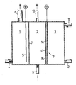
- an electrochemical cell for the electrolysis of aqueous sodium chloride solutions is shown schematically, which is equipped with a gas diffusion electrode.
- the cell is divided into an anode compartment (1), a cathode compartment (2) and a gas compartment (3).
- Saturated sodium chloride brine is pumped into the anode compartment (1) via a feed line (4).
- Chloride ions are discharged to elemental chlorine at the anode (5).
- Dimensionally stable anodes made of titanium are preferably used, which are equipped with an activation in order to keep the chlorine overvoltage low.
- the chlorine formed and the depleted brine leave the anode compartment (1) via line (6).
- the reactant water is fed via the feed line (9) to the cell in the form of deionized water or dilute sodium hydroxide solution.
- Sodium hydroxide solution is formed in the cathode compartment (2) and leaves the cell via the opening (10).
- the cathode compartment (2) and the gas compartment (3) are separated from one another by the gas diffusion electrode (8), which serves as the cathode.
- An oxygen-containing gas (pure oxygen, CO 2 -free air or oxygen-enriched and / or humidified air) is introduced into the gas space (3) via pipe (11). The gas penetrates the diffusion electrode, reducing oxygen. The remaining gas finally leaves the cell, generally depleted of oxygen, via line (12).
- the electrode (8) represents a porous body that allows the access of the reactants water and oxygen. It mainly consists of an electrochemically active material that catalyzes oxygen reduction.
- the electrode is often manufactured in a supported form, i.e. a mesh-shaped current collector made of metal is incorporated into the electrocatalyst layer or supports it from the outside.
- Porous metals such as platinum black, silver black or nickel black, other substances such as phthalocyanines, mixed oxides of the spinel or perovskite type and activated carbon, which can be activated with a catalyst suitable for oxygen reduction, serve as the electrocatalyst.
- a hydrophobic material preferably polytetrafluoroethylene (PTFE)
- PTFE polytetrafluoroethylene
- Hydrophobic electrodes containing PTFE are described, for example, in U.S. Patents 43 50 608, 43 39 325, 4 179 350, 3 977 901 and 3 537 906.
- the required cell voltage of such a cell is composed of the electrode potentials, the overvoltages on the two electrodes, the membrane resistance and the voltage drop within the electrolyte.
- the overvoltages on the electrodes can be influenced by selecting a suitable electrochemically active electrode material.
- the membrane resistance is constant and given by the choice of the cation exchange membrane.
- the electrolyte resistance can be reduced by bringing the two electrodes as close together as possible. Since the cell has to be supplied with water, the distance between cathode and anode cannot be less than a certain amount. In practice, however, the distance between the membrane and the gas diffusion electrode will be kept as small as possible. Distances between 0.5 and 3 mm, in particular between 0.5 and 1 mm, have proven effective.
- the object was therefore to prevent the gas bubbles from adhering to the oxygen diffusion cathode and to ensure that any gas bubbles (air or D 2 ) formed are discharged from the catholyte gap.
- the present invention solves this problem by using a gas diffusion electrode for oxygen reduction which contains a hydrophobic electrocatalyst layer and which is characterized in that one side of the electrocatalyst layer is covered with a hydrophilic layer consisting of at least one transition metal or an oxide or mixed oxide of transition metals .
- the electrode according to the invention preferably has the shape of a flat surface. It is particularly suitable for oxygen reduction in an alkaline environment, i.e. under the conditions of aqueous chlor-alkali electrolysis. Gas bubbles are prevented from adhering to the hydrophilically coated side. Surprisingly, such coated electrodes have a higher electrochemical activity and thus a lower overvoltage than uncoated electrodes.
- the transition metals which serve in the form of the metals or oxides of the coating, are selected in particular from the group consisting of titanium, chromium, manganese, iron, cobalt, nickel, copper, zinc, silver, ruthenium, rhodium, palladium, osmium, iridium and Platinum. Coating with the electrocatalytically active metals silver and platinum is advantageous, but especially with nickel. To apply nickel with a particularly large surface area, one can proceed by first coating with a nickel-aluminum alloy and later removing the aluminum portion of the alloy by treatment with aqueous alkali.
- the hydrophobic electrocatalyst layer is preferably produced on the basis of metallic silver.
- the electrode (8) according to the invention can be seen schematically in cross section in the figure.
- An embodiment is shown in which the current is supplied by a network-shaped current collector (13).
- This is preferably a metal network made of nickel or silver-plated nickel which, in addition to the current supply, also takes over the current distribution within the catalyst layer (14).
- the hydrophilic cover layer (15) is applied to (14). It prevents gas bubbles from sticking to the electrode surface and facilitates the supply of water to the actual reaction zone and the removal of hydroxyl ions formed.
- the reaction takes place at the three-phase water-oxygen electrocatalyst, which should form within (14).
- hydrophilic coating material which is as finely divided as possible, in particular material with a particle size of less than 0.063 mm. Very fine fractions can be obtained by grinding, chopping in a cross beater mill or mortar, and subsequent sieving.
- the thickness of the coating with hydrophilic material should be between 1 and 200, in particular 2 and 50, preferably 2.5 and 20 mg / em 2.
- the gas diffusion electrode according to the invention can be produced by first producing a hydrophobic catalyst layer (usually in the form of a flat surface) from a powdery mixture which contains an electrocatalyst and a hydrophobic polymer. At least one transition metal or an oxide or mixed oxide of transition metals is applied to one side of this layer in finely divided form and connected to the hydrophobic electrocatalyst layer by applying pressure.
- the electrophilic layer for example, a suspension of a specified hydrophilic material in water or in an organic solvent (such as alcohol, methylene chloride or petroleum ether) on the hydrophobic electro Apply the catalyst layer and allow the liquid phase to evaporate there.
- the specified suspension can also be filtered, the hydrophobic electrocatalyst layer being the filter, or the hydrophilic material in powder form can be applied uniformly to the electrocatalyst layer, e.g. by means of a sieve. Subsequent pressing or rolling (exposure to pressure) intimately connects the coating material to the raw electrode.
- the use of heat is advantageous here because the hydrophobic portion of the electrocatalyst layer becomes thermoplastic at least at high temperatures.
- hydrophobic electrocatalyst layers produced in another way can also be coated according to the invention.
- An electrode was produced as in Example 1, except that a manganese dioxide was used instead of zinc oxide, the largest particles of which pass through a sieve with a mesh size of 0.06 mm.
- the electrode coverage was approximately 16 mg / cm 2 of MnO 2 .
- the measured potentials vs GKE are shown in Table 1.
- Example 1 was repeated, but silver oxide was used as the coating material (24 mg / cm 2 ).
- the measured potentials vs GKE can be found in Table 1.
- An electrode was produced analogously to Example 1, but using iron powder with a grain size of 0.06 mm as the coating material.
- the coverage of the electrode with iron was about 28 mg / cm 2 .
- the measured potentials vs GKE are shown in Table 1.
- An electrode was produced in the same way as in Example 1, except that nickel powder with a grain size of 0.06 mm was used as the coating material.
- the coverage of the electrode with nickel was about 36 mg / cm 2 .
- the measured potentials vs GKE are listed in Table 1.
- An electrode was produced as in Example 1, except that silver powder was used for the coating instead of zinc oxide.
- the coverage of this electrode with silver was about 18 mg / cm2.
- the measured potentials vs GKE are listed in Table 1.
- aqueous polytetrafluoroethylene dispersion (trade name Hostaflon @ TF 5033-40%) are added 280 ml of water and 45 ml of a 35% formaldehyde solution and the mixture is cooled to 0 to 10 ° C.
- a solution of 30.3 g of silver nitrate and 3.2 g of mercury (II) nitrate in 450 ml of water and 310 ml of a 10% potassium hydroxide solution are added dropwise over the course of about 3.5 hours.
- the reaction mixture is mixed vigorously; the reaction temperature should not exceed 15 ° C.
- the potassium hydroxide solution must be dosed so that the pH does not rise above 10; the pH should not fall below 7.5. After the reaction has ended, the precipitate formed is allowed to settle, the supernatant mother liquor is decanted off and the remaining solid is washed first with water and then with petroleum ether. After drying at 110 ° C, the yield of catalyst material is 24.8 g.
- the silver content of the material produced in this way is approximately 77% by weight, the mercury content 8% by weight.
- the still moist filter cake was pressed at a pressure of 20 bar into a silver-plated nickel mesh with a mesh size of 0.25 mm and a wire thickness of 0.16 mm. After drying for one hour at 110 ° C., the raw electrode was dusted with 170 mg of a nickel-aluminum alloy, each consisting of 50% by weight of the two metals. The particle size was less than 0.063 mm. The dusted electrode was then pressed at a pressure of 60 bar and sintered at 250 ° C. for 15 minutes. The sintered electrode was placed in a 10% sodium hydroxide solution for 15 hours in order to dissolve out the aluminum and the sodium chloride serving as pore former.
- the coating on the electrode was about 65 mg / cm 2 of catalyst and about 6 mg / cm 2 of Raney nickel coating.
- the measured potentials against a saturated calom electrode are listed in Table 1.
- An analog electrode with an active area of 40 cm 2 was operated in an electrolysis cell for 20 weeks, producing 8.25N sodium hydroxide solution.
- the cell voltage was 2.14 V.
- the cathode gap was only 1 mm wide, no adhesion of gas bubbles between the electrode and the cation exchange membrane was observed.
- An electrode was produced analogously to Example 1, but without coating with Zn O.
- the potentials vs GKE of this electrode are listed in Table 1.
- Gas bubbles that pass through the electrode adhere to the surface of the electrode and can often only be expelled by shaking the electrolysis cell. The "gas bubble effect" occurs, the cell voltage increases by up to 200 mV. If the gas bubbles are expelled due to vibrations in the electrolysis cell, the cell voltage drops to the initial value.
Abstract
Description
Die vorliegende Erfindung betrifft eine-Gasdiffusionskathode für die Sauerstoffreduktion in alkalischer Lösung, die auf einer Seite mit einer hydrophilen Deckschicht versehen ist.The present invention relates to a gas diffusion cathode for oxygen reduction in alkaline solution, which is provided on one side with a hydrophilic cover layer.
Die wäßrige Natriumchlorid-Elektrolyse ist ein wichtiges Verfahren zur Herstellung der Schwerchemikalien Chlor und Natronlauge. Eine moderne Variante wird in einer Membranzelle durchgeführt. Bei diesem Verfahren besteht die Elektrolyse-Zelle aus einem Anodenraum mit einer Anode und einem Kathodenraum mit einer Kathode, sowie einer Kationenaustauscher-Membran, die beide Elektrolyseräume trennt. Wenn man in den Anodenraum eine gesättigte Natriumchlorid-Lösung einspeist, so werden unter der Einwirkung des elektrischen Stroms die Chloridionen an der Anode zu elementarem Chlor entladen. Gleichzeitig findet an der Kathode eine Zerlegung von Wasser unter Bildung von elementarem Wasserstoff und Hydroxidionen statt. Etwa in gleichem Maße wie Hydroxidionen erzeugt werden, wandern Natriumionen aus dem Anodenraum durch die Membran in den Kathodenraum..Die zugrundeliegende chemische Reaktion entspricht der folgenden Gleichung:Aqueous sodium chloride electrolysis is an important process for the production of the heavy chemicals chlorine and sodium hydroxide. A modern variant is carried out in a membrane cell. In this method, the electrolysis cell consists of an anode compartment with an anode and a cathode compartment with a cathode, and a cation exchange membrane that separates the two electrolysis compartments. If a saturated sodium chloride solution is fed into the anode compartment, the chloride ions at the anode are discharged to elemental chlorine under the influence of the electric current. At the same time, water is broken down at the cathode to form elemental hydrogen and hydroxide ions. Sodium ions migrate from the anode space through the membrane into the cathode space to approximately the same extent as hydroxide ions are generated. The underlying chemical reaction corresponds to the following equation:
![]()
![]()
Der entstehende Wasserstoff stellt ein unerwünschtes Nebenprodukt dar. Das Potential für die Wasserstoffabscheidung gemäß der Gleichung
![]()
![]()
![]()
![]()
Das Potential dieser Reaktion beträgt + 0,40 V bezogen auf die Standardwasserstoff-Elektrode. Durch die Polarisation, wie sie in Sauerstoffdiffusionskathoden stattfindet, können folglich bei der Chloralkali-Elektrolyse theoretisch 1,23 V an Zellspannung eingespart werden. Dies ist in Zeiten hoher Energiekosten von erheblicher wirtschaftlicher Bedeutung.The potential of this reaction is + 0.40 V based on the standard hydrogen electrode. Due to the polarization, as it takes place in oxygen diffusion cathodes, theoretically 1.23 V in cell voltage can be saved in chlor-alkali electrolysis. This is of considerable economic importance in times of high energy costs.
In der Figur ist schematisch eine elektrochemische Zelle zur Elektrolyse wäßriger Natriumchlorid-Lösungen dargestellt, die mit einer Gasdiffusionselektrode ausgerüstet ist. Die Zelle ist in einen Anodenraum (1), einen Kathodenraum (2) und einen Gasraum (3) unterteilt. Ober eine Zuleitung (4) wird gesättigte Natriumchlorid-Sole in den Anodenraum (1) gepumpt. An der Anode (5) werden Chloridionen zu elementarem Chlor entladen. Vorzugsweise werden dimensionsstabile Anoden aus Titan eingesetzt, die mit einer Aktivierung ausgestattet sind, um die Chlorüberspannung gering zu halten. Über Leitung (6) verlassen das gebildete Chlor und die verarmte Sole den Anodenraum (1). Zwischen (1) und Kathodenraum (2) befindet sich eine KationenaustauscherMembran (7), durch die Natriumionen unter dem Einfluß des elektrischen Stromes in den Kathodenraum wandern.In the figure, an electrochemical cell for the electrolysis of aqueous sodium chloride solutions is shown schematically, which is equipped with a gas diffusion electrode. The cell is divided into an anode compartment (1), a cathode compartment (2) and a gas compartment (3). Saturated sodium chloride brine is pumped into the anode compartment (1) via a feed line (4). Chloride ions are discharged to elemental chlorine at the anode (5). Dimensionally stable anodes made of titanium are preferably used, which are equipped with an activation in order to keep the chlorine overvoltage low. The chlorine formed and the depleted brine leave the anode compartment (1) via line (6). Between (1) and cathode compartment (2) there is a cation exchange membrane (7) through which sodium ions migrate into the cathode compartment under the influence of the electric current.
Der Reaktionspartner Wasser wird über die Zuleitung (9) der Zelle in Form von entionisiertem Wasser oder verdünnter Natronlauge zugeführt. Im Kathodenraum (2) wird Natronlauge gebildet, die die Zelle über die Öffnung (10) verläßt.The reactant water is fed via the feed line (9) to the cell in the form of deionized water or dilute sodium hydroxide solution. Sodium hydroxide solution is formed in the cathode compartment (2) and leaves the cell via the opening (10).
Kathodenraum (2) und Gasraum (3) werden durch die Gasdiffusionselektrode (8) voneinander getrennt, die als Kathode dient. In den Gasraum (3) wird über Rohr (11) ein Sauerstoff enthaltendes Gas (reiner Sauerstoff, C02-freie Luft oder mit Sauerstoff angereicherte und/oder befeuchtete Luft) eingeleitet. Das Gas dringt in die Diffusionselektrode ein, wobei Sauerstoff reduziert wird. Das restliche Gas verläßt schließlich, im allgemeinen an Sauerstoff verarmt, über die Leitung (12) die Zelle.The cathode compartment (2) and the gas compartment (3) are separated from one another by the gas diffusion electrode (8), which serves as the cathode. An oxygen-containing gas (pure oxygen, CO 2 -free air or oxygen-enriched and / or humidified air) is introduced into the gas space (3) via pipe (11). The gas penetrates the diffusion electrode, reducing oxygen. The remaining gas finally leaves the cell, generally depleted of oxygen, via line (12).
Die Elektrode (8) stellt einen porösen Körper dar, der den Zutritt der Reaktionspartner Wasser und Sauerstoff erlaubt. In der Hauptsache besteht sie aus einem elektrochemisch aktiven Material, das die Sauerstoffreduktion katalysiert. Häufig wird die Elektrode in gestützter Form gefertigt, d.h. ein netzförmiger, aus Metall bestehender Stromkollektor ist in die Elektrokatalysatorschicht eingearbeitet oder stützt sie von außen. Als Elektrokatalysator dienen poröse Metalle wie Platinschwarz, Silberschwarz oder Nickelschwarz, andere Stoffe, wie Phthalocyanine,Mischoxide vom Spinell-oder Perowskit-Typ und Aktivkohle, die mit einem für die Sauerstoffreduktion geeigneten Katalysator aktiviert sein kann.The electrode (8) represents a porous body that allows the access of the reactants water and oxygen. It mainly consists of an electrochemically active material that catalyzes oxygen reduction. The electrode is often manufactured in a supported form, i.e. a mesh-shaped current collector made of metal is incorporated into the electrocatalyst layer or supports it from the outside. Porous metals such as platinum black, silver black or nickel black, other substances such as phthalocyanines, mixed oxides of the spinel or perovskite type and activated carbon, which can be activated with a catalyst suitable for oxygen reduction, serve as the electrocatalyst.
Damit sich die Poren der Elektrode beim Betrieb nicht vollständig mit Elektrolyt füllen und somit die Sauerstoffzufuhr unterbunden wird, ist häufig in das elektrochemisch aktive Material ein hydrophobes Material, vorzugsweise Polytetrafluorethylen (PTFE), eingearbeitet. Man kann auch lediglich eine Außenseite mit einer hydrophoben Deckschicht aus nicht aktivierter Aktivkohle/PTFE überziehen (europäische Patentanmeldung 051 432 ). Hydrophobe Elektroden, die PTFE enthalten, sind beispielsweise in den US-Patentschriften 43 50 608, 43 39 325, 4 179 350, 3 977 901 und 3 537 906 beschrieben.So that the pores of the electrode are not completely filled with electrolyte during operation and thus the oxygen supply is prevented, a hydrophobic material, preferably polytetrafluoroethylene (PTFE), is often incorporated into the electrochemically active material. You can also just coat an outside with a hydrophobic top layer made of non-activated activated carbon / PTFE (European patent application 051 432). Hydrophobic electrodes containing PTFE are described, for example, in U.S. Patents 43 50 608, 43 39 325, 4 179 350, 3 977 901 and 3 537 906.
Die erforderliche Zellspannung einer solchen Zelle setzt sich zusammen aus den Elektrodenpotentialen, den überspannungen an den beiden Elektroden, dem Membranwiderstand und dem Spannungsabfall innerhalb des Elektrolyten. Die Überspannungen an den Elektroden sind beeinflußbar, durch Auswahl eines geeigneten elektrochemisch aktiven Elektrodenmaterials. Der Membranwiderstand ist konstant und durch die Wahl der Kationenaustauschermembran gegeben. Der Elektrolytwiderstand kann vermindert werden, indem man die beiden Elektroden möglichst nahe aneinander bringt. Da man die Zelle mit Wasser versorgen muß, kann der Abstand zwischen Kathode und Anode ein bestimmtes Maß nicht unterschreiten. In der Praxis wird man jedoch den Abstand zwischen Membran und Gasdiffusionselektrode möglichst gering halten. Bewährt haben sich Abstände zwischen 0,5 und 3 mm, insbesondere zwischen 0,5 und 1 mm. Dieser geringe Abstand kann beim Betreiben einer Zelle jedoch auch nachteilig sein. Wenn die Elektrode etwas Gas durchläßt, was beispielsweise bei gealterten Elektroden oder bei Elektroden mit kleinen mechanischen Verletzungen der Fall ist, so bilden sich auf der Ka tholytseite der Kathode (= Gasdiffusionselektrode) Gasblasen aus, die den Stofftransport erschweren und den elektrischen Widerstand erhöhen. Daher steigt die Zellspannung an. Wegen des kleinen Abstandes von Membran und Kathode besteht zusätzlich die Gefahr, daß die Gasblasen im Katholytspalt an der hydrophoben Membran und der hydrophoben Kathode haften bleiben, d.h. nicht von der erzeugten Lauge mitgerissen werden. Dies hat zur Folge, daß nicht nur der Widerstand im Elektrolyten größer wird, sondern auch Teile der Kathodenfläche für die Reaktion blockiert werden.The required cell voltage of such a cell is composed of the electrode potentials, the overvoltages on the two electrodes, the membrane resistance and the voltage drop within the electrolyte. The overvoltages on the electrodes can be influenced by selecting a suitable electrochemically active electrode material. The membrane resistance is constant and given by the choice of the cation exchange membrane. The electrolyte resistance can be reduced by bringing the two electrodes as close together as possible. Since the cell has to be supplied with water, the distance between cathode and anode cannot be less than a certain amount. In practice, however, the distance between the membrane and the gas diffusion electrode will be kept as small as possible. Distances between 0.5 and 3 mm, in particular between 0.5 and 1 mm, have proven effective. However, this small distance can also be disadvantageous when operating a cell. If the electrode allows some gas to pass through, which is the case, for example, with aged electrodes or with electrodes with small mechanical injuries, then gas bubbles form on the catholyte side of the cathode (= gas diffusion electrode), which make mass transport more difficult and increase the electrical resistance. Therefore, the cell voltage increases. Because of the small distance between the membrane and the cathode, there is additionally the risk that the gas bubbles in the catholyte gap adhere to the hydrophobic membrane and the hydrophobic cathode, i.e. not to be carried away by the lye produced. As a result, not only the resistance in the electrolyte increases, but also parts of the cathode surface are blocked for the reaction.
Es bestand daher die Aufgabe, das Haften der Gasblasen an der Sauerstoffdiffusions-Kathode zu verhindern und zu gewährleisten, daß eventuell gebildete Gasblasen .(Luft oder D2) aus dem Katholytspalt ausgetragen werden.The object was therefore to prevent the gas bubbles from adhering to the oxygen diffusion cathode and to ensure that any gas bubbles (air or D 2 ) formed are discharged from the catholyte gap.
Die vorliegende Erfindung löst dieses Problem durch Einsatz einer Gasdiffusionselektrode für die Sauerstoffreduktion, die eine hydrophobe Elektrokatalysatorschicht enthält und die dadurch gekennzeichnet ist, daß eine Seite der Elektrokatalysatorschicht mit einer hydrophilen Schicht bedeckt ist, die aus mindestens einem Übergangsmetall oder einem Oxid oder Mischoxid von Übergangsmetallen besteht.The present invention solves this problem by using a gas diffusion electrode for oxygen reduction which contains a hydrophobic electrocatalyst layer and which is characterized in that one side of the electrocatalyst layer is covered with a hydrophilic layer consisting of at least one transition metal or an oxide or mixed oxide of transition metals .
Die erfindungsgemäße Elektrode hat vorzugsweise die Form einer ebenen Fläche. Sie eignet sich besonders gut für die Sauerstoff-Reduktion im alkalischen Milieu, also unter Bedingungen der wäßrigen Chloralkali-Elektrolyse. An der hydrophil beschichteten Seite wird das Anhaften.von Gasblasen verhindert. Überraschenderweise besitzen solche beschichteten Elektroden eine höhere elektrochemische Aktivität und damit geringere Überspannung als unbeschichtete Elektroden.The electrode according to the invention preferably has the shape of a flat surface. It is particularly suitable for oxygen reduction in an alkaline environment, i.e. under the conditions of aqueous chlor-alkali electrolysis. Gas bubbles are prevented from adhering to the hydrophilically coated side. Surprisingly, such coated electrodes have a higher electrochemical activity and thus a lower overvoltage than uncoated electrodes.
Die Übergangsmetalle, die in Form der Metalle oder Oxide der Beschichtung dienen, werden insbesondere ausgewählt aus der Gruppe bestehend aus Titan, Chrom, Mangan, Eisen, Kobalt, Nickel, Kupfer, Zink, Silber, Ruthenium, Rhodium, Palladium, Osmium, Iridium und Platin. Günstig ist eine Beschichtung mit den elektrokatalytisch wirksamen Metallen Silber und Platin insbesondere aber mit Nickel. Zum Auftragen von Nickel mit besonders großer Oberfläche kann man so vorgehen, daß man zunächst mit einer Nickel-Aluminium-Legierung beschichtet und später durch Behandlung mit wäßriger Lauge den Aluminiumanteil der Legierung herauslöst. Dies kann sowohl vor dem Einbau der Elektrode in die Zelle als auch während des Einsatzes als Kathode bei der wäßrigen Alkalichlorid-Elektrolyse durch das entstehende Alkalihydroxid geschehen. Es können auch Legierungen verwendet werden, die mehrere Übergangsmetalle enthalten sowie Gemische von Oxiden von Übergangsmetallen. Bei einer Beschichtung mit Oxiden, sind Oxide aus der Gruppe Titanoxid, Mangan-IV-oxid, Zinkoxid und Silberoxid bevorzugt. Es ist ferner möglich, mehrere verschiedene Oxide nacheinander auf die hydrophobe Elektrokatalysatorschicht aufzubringen.The transition metals, which serve in the form of the metals or oxides of the coating, are selected in particular from the group consisting of titanium, chromium, manganese, iron, cobalt, nickel, copper, zinc, silver, ruthenium, rhodium, palladium, osmium, iridium and Platinum. Coating with the electrocatalytically active metals silver and platinum is advantageous, but especially with nickel. To apply nickel with a particularly large surface area, one can proceed by first coating with a nickel-aluminum alloy and later removing the aluminum portion of the alloy by treatment with aqueous alkali. This can take place both before the electrode is installed in the cell and during use as a cathode in the aqueous alkali metal chloride electrolysis by means of the alkali metal hydroxide formed. Alloys containing several transition metals and mixtures of oxides of transition metals can also be used. In the case of a coating with oxides, oxides from the group consisting of titanium oxide, manganese IV oxide, zinc oxide and silver oxide are preferred. It is also possible to apply several different oxides in succession to the hydrophobic electrocatalyst layer.
Vorzugsweise wird die hydrophobe Elektrokatalysatorschicht auf Basis von.metallischem Silber hergestellt.The hydrophobic electrocatalyst layer is preferably produced on the basis of metallic silver.
In der Figur ist die erfindungsgemäße Elektrode (8) schematisch im Querschnitt zu erkennen. Gezeigt wird eine Ausführungsform, bei der die Stromzuführung durch einen netzförmigen Stromkollektor (13) erfolgt. Vorzugsweise handelt es sich dabei um ein Metallnetz aus Nickel oder versilbertem Nickel, das neben der Stromzuführung auch die Stromverteilung innerhalb der Katalysatorschicht (14) übernimmt. Auf (14) ist die hydrophile Deckschicht (15) aufgebracht. Sie verhindert das Haften von Gasblasen an der Elektrodenoberfläche und erleichtert die Versorgung der eigentlichen Reaktionszone mit Wasser und die Abführung gebildeter Hydroxylionen. Die Reaktion findet an der Dreiphasengrenze Wasser-Sauerstoff-Elektrokatalysator statt, die sich innerhalb von (14) ausbilden soll.The electrode (8) according to the invention can be seen schematically in cross section in the figure. An embodiment is shown in which the current is supplied by a network-shaped current collector (13). This is preferably a metal network made of nickel or silver-plated nickel which, in addition to the current supply, also takes over the current distribution within the catalyst layer (14). The hydrophilic cover layer (15) is applied to (14). It prevents gas bubbles from sticking to the electrode surface and facilitates the supply of water to the actual reaction zone and the removal of hydroxyl ions formed. The reaction takes place at the three-phase water-oxygen electrocatalyst, which should form within (14).
Es ist vorteilhaft, ein möglichst feinteiliges hydrophiles Beschichtungsmaterial einzusetzen, insbesondere Material der Teilchengröße unter 0,063 mm. Sehr feine Fraktionen lassen sich durch Mahlen, Zerhacken in einer Schlagkreuzmühle oder Mörsern, sowie nachfolgendes Absieben erhalten. Die Stärke der Beschichtung mit hydrophilem Material soll zwischen 1 und 200, insbesondere 2 und 50, vorzugsweise 2,5 und 20 mg/em2 betragen.It is advantageous to use a hydrophilic coating material which is as finely divided as possible, in particular material with a particle size of less than 0.063 mm. Very fine fractions can be obtained by grinding, chopping in a cross beater mill or mortar, and subsequent sieving. The thickness of the coating with hydrophilic material should be between 1 and 200, in particular 2 and 50, preferably 2.5 and 20 mg /
Die erfindungsgemäße Gasdiffusionselektrode läßt sich dadurch herstellen, daß man zunächst aus einem pulverförmigen Gemisch, das Elektrokatalysator und ein hydrophobes Polymer enthält, eine hydrophobe Katalysatorschicht (meist in Form einer ebenen Fläche) erzeugt. Auf einer Seite dieser Schicht wird in feinverteilter Form mindestens ein Übergangsmetall oder ein Oxid oder Mischoxid von Übergangsmetallen aufgebracht und durch Anwendung von Druck mit der hydrophoben Elektrokatalysatorschicht verbunden.The gas diffusion electrode according to the invention can be produced by first producing a hydrophobic catalyst layer (usually in the form of a flat surface) from a powdery mixture which contains an electrocatalyst and a hydrophobic polymer. At least one transition metal or an oxide or mixed oxide of transition metals is applied to one side of this layer in finely divided form and connected to the hydrophobic electrocatalyst layer by applying pressure.
Zur Herstellung der elektrophilen Schicht kann man z.B. eine Suspension eines angegebenen hydrophilen Materials in Wasser oder 'in einem organischen Lösungsmittel (wie z.B. Alkohol, Methylenchlorid oder Petroläther) auf die hydrophobe Elektrokatalysatorschicht aufbringen und dort die flüssige Phase verdunsten lassen. Man kann ferner die angegebene Suspension filtrieren, wobei die hydrophobe Elektrokatalysatorschicht das Filter darstellt, oder man kann das hydrophile Material in Pulverform gleichmäßig auf der Elektrokatalysatorschicht auftragen, z .B. mittels eines Siebes. Durch anschließendes Pressen oder Rollen (Einwirkung von Druck) wird das Beschichtungsmaterial mit der Rohelektrode innig verbunden. Dabei ist die Anwendung von Hitze vorteilhaft, weil der hydrophobe Anteil der Elektrokatalysatorschicht zumindest bei hohen Temperaturen thermoplastisch wird.To produce the electrophilic layer, for example, a suspension of a specified hydrophilic material in water or in an organic solvent (such as alcohol, methylene chloride or petroleum ether) on the hydrophobic electro Apply the catalyst layer and allow the liquid phase to evaporate there. The specified suspension can also be filtered, the hydrophobic electrocatalyst layer being the filter, or the hydrophilic material in powder form can be applied uniformly to the electrocatalyst layer, e.g. by means of a sieve. Subsequent pressing or rolling (exposure to pressure) intimately connects the coating material to the raw electrode. The use of heat is advantageous here because the hydrophobic portion of the electrocatalyst layer becomes thermoplastic at least at high temperatures.
Sehr gute Ergebnisse wurden erhalten, wenn die hydrophobe Elektrokatalysatorschicht durch reduktive Abscheidung von Silber auf den kleinen suspendierten Teilchen eines Kunststoff Latex gemäß deutscher Patentanmeldung P 33 03 779.5 erzeugt wird. Dabei wird bei 0 - 50°C eine wäßrige Dispersion eines hydrophoben organischen Polymeren (insbesondere PTFE), eine Silbersalz-Lösung und ein Reduktionsmittel für Silberionen (z.B. Formaldehyd) vereint und dabei ein pH-Wert eingehalten, bei dem die eingesetzte Dispersion stabil ist und das Silbersalz reduziert wird. Für PTFE-Dispersionen eignen sich pH-Werte von 4 bis 11, insbesondere 9 bis 10. Bezogen auf die Menge der Einsatzprodukte beträgt das Gewichtsverhältnis Silber/Trockenanteil der organischen Dispersion 20:80 bis 90:10.Very good results were obtained when the hydrophobic electrocatalyst layer was produced by reductive deposition of silver on the small suspended particles of a plastic latex in accordance with German patent application P 33 03 779.5. At 0 - 50 ° C, an aqueous dispersion of a hydrophobic organic polymer (especially PTFE), a silver salt solution and a reducing agent for silver ions (e.g. formaldehyde) are combined while maintaining a pH at which the dispersion used is stable and the silver salt is reduced. For PTFE dispersions, pH values from 4 to 11, in particular 9 to 10, are suitable. Based on the amount of the products used, the silver / dry weight ratio of the organic dispersion is 20:80 to 90:10.
Es können aber auch auf anderem Wege hergestellte hydrophobe Elektrokatalysatorschichten erfindungsgemäß beschichtet werden.However, hydrophobic electrocatalyst layers produced in another way can also be coated according to the invention.
Die Erfindung wird durch die folgenden Beispiele näher erläutert.The invention is illustrated by the following examples.
Zu 4,7 g einer käuflichen 40 $igen wäßrigen Polytetrafluorethylen-Dispersion (Handelsname Hostaflon(R)TF 5033) gibt man 80 ml Wasser und 30ml einer 35 %igen Formaldehydlösung und kühlt diese Mischung auf 0 bis 10°C ab. Hierzu tropft man im Verlauf von etwa einer Stunde einmal eine Lösung von 16,7 g Silbernitrat in 130 ml Wasser, sowie 130 ml einer 10 %igen Kaliumhydroxid-Lösung. Während des Zutropfens wird das Reaktionsgemisch kräftig durchgemischt; die Reaktionstemperatur soll 15°C nicht überschreiten. Die Dosierung der Kalilauge soll so durchgeführt werden, daß der pH-Wert nicht über 10 ansteigt und nicht unter 7,5 absinkt. Nach Beendigung der Reaktion läßt man den gebildeten Niederschlag absitzen und dekantiert die überstehende Mutterlauge ab. Der zurückbleibende Feststoff wird zunächst mit 100 ml Wasser, dann mit 200 ml Petrolether gewaschen und der so erhaltene Elektrokatalysator bei 120°C getrocknet (Ausbeute 12,3 g, Silbergehalt etwa 85 Gew.-%).80 ml of water and 30 ml of a 35% formaldehyde solution are added to 4.7 g of a commercially available 40% aqueous polytetrafluoroethylene dispersion (trade name Hostaflon (R) TF 5033) and this mixture is cooled to 0 to 10 ° C. For this purpose, a solution of 16.7 g of silver nitrate in 130 ml of water and 130 ml of a 10% potassium hydroxide solution are dripped once over the course of about an hour. During the dropping, the reaction mixture is mixed vigorously; the reaction temperature should not exceed 15 ° C. The potassium hydroxide solution should be metered in such a way that the pH does not rise above 10 and does not fall below 7.5. After the reaction has ended, the precipitate formed is allowed to settle and the supernatant mother liquor is decanted off. The remaining solid is washed first with 100 ml of water and then with 200 ml of petroleum ether and the electrocatalyst obtained in this way is dried at 120 ° C. (yield 12.3 g, silver content about 85% by weight).
2 g Elektrokatalysator werden in einer Schlagkreuzmühle (Hersteller: Janke und Kunkel, Staufen) bei 20.000/min 10 sec. zerhackt und anschließend in 20 ml Isopropanol suspendiert. Die so erhaltene Suspension gießt man in ein Membranfilter mit einem Innendurchmesser von 4,2 cm und saugt das Lösungsmittel ab, bis ein noch feuchter Filterkuchen verbleibt. Diesen preßt man anschließend mit einem Druck von 19,6 bar in ein versilbertes Nickelnetz der Maschenweite 0,25 mm und der Drahtstärke 0,16 mm. Nach dem Trocknen bei 110°C im Trockenschrank ist die Rohelektrode bereit zur Beschichtung. 170 mg gemörsertes Zinkoxid werden durch ein Metallnetz der Maschenweite 0,063 mm auf die Rohelektrode aufgesiebt. Durch einen Druck von 60 bar wird dann das Zinkoxid mit einem Stempel in die Oberfläche der .Elektrode eingepreßt und diese anschließend bei 250°C gesintert. Die so hergestellte Gasdiffusionselektrode. hat eine Belegung an Zinkoxid von etwa 12 mg/cm . Die gemessenen Potentiale gegen eine gesättigte Kalomelelektrode (GKE) dieser Elektrode sind in Tabelle 1 aufgeführt.2 g of electrocatalyst are chopped in a cross beater mill (manufacturer: Janke and Kunkel, Staufen) at 20,000 rpm for 10 seconds and then suspended in 20 ml of isopropanol. The suspension thus obtained is poured into a membrane filter with an inner diameter of 4.2 cm and the solvent is suctioned off until a filter cake which is still moist remains. This is then pressed into a silver-plated nickel mesh with a mesh size of 0.25 mm and a wire thickness of 0.16 mm at a pressure of 19.6 bar. After drying at 110 ° C in the drying cabinet, the raw electrode is ready for coating. 170 mg of ground zinc oxide are sieved through a metal mesh with a mesh size of 0.063 mm onto the raw electrode. The zinc oxide is then pressed into the surface of the .electrode by means of a pressure and then sintered at 250.degree. The gas diffusion electrode thus produced. has an occupancy of zinc oxide of about 12 mg / cm. The Measured potentials against a saturated calomel electrode (GKE) of this electrode are listed in Table 1.
Es wurde eine Elektrode analog Beispiel 1 hergestellt, außer daß anstatt Zinkoxid ein Mangandioxid verwendet wurde, dessen größte Teilchen ein Sieb der Maschenweite 0,06 mm passieren. Die Belegung der Elektrode betrug etwa 16 mg/cm2 an MnO2.An electrode was produced as in Example 1, except that a manganese dioxide was used instead of zinc oxide, the largest particles of which pass through a sieve with a mesh size of 0.06 mm. The electrode coverage was approximately 16 mg / cm 2 of MnO 2 .
Die gemessenen Potentiale vs GKE sind in Tabelle 1 dargestellt.The measured potentials vs GKE are shown in Table 1.
Beispiel 1 wurde wiederholt, jedoch Silberoxid als Beschichtungsmaterial (24 mg/cm2) verwendet. Die gemessene Potentiale vs GKE finden sich in Tabelle 1.Example 1 was repeated, but silver oxide was used as the coating material (24 mg / cm 2 ). The measured potentials vs GKE can be found in Table 1.
Es wurde eine Elektrode analog Beispiel 1 hergestellt, dabei jedoch Eisenpulver der Korngröße 0,06 mm als Beschichtungsmaterial verwendet. Die Belegung der Elektrode mit Eisen betrug etwa 28 mg/cm2. Die gemessenen Potentiale vs GKE sind in Tabelle 1 ausgeführt.An electrode was produced analogously to Example 1, but using iron powder with a grain size of 0.06 mm as the coating material. The coverage of the electrode with iron was about 28 mg / cm 2 . The measured potentials vs GKE are shown in Table 1.
Es wurde eine Elektrode analog Beispiel 1 hergestellt, außer daß Nickelpulver der Korngröße 0,06 mm als Beschichtungsmaterial verwendet wurde. Die Belegung der Elektrode mit Nickel betrug etwa 36 mg/cm2. Die gemessenen Potentiale vs GKE sind in Tabelle 1 aufgeführt.An electrode was produced in the same way as in Example 1, except that nickel powder with a grain size of 0.06 mm was used as the coating material. The coverage of the electrode with nickel was about 36 mg / cm 2 . The measured potentials vs GKE are listed in Table 1.
Es wurde eine Elektrode analog Beispiel 1 hergestellt, außer daß anstatt Zinkoxid Silberpulver zur Beschichtung verwendet wurde. Die Belegung dieser Elektrode mit Silber betrug etwa 18 mg/cm2. Die gemessenen Potentiale vs GKE sind in Tabelle 1 aufgeführt.An electrode was produced as in Example 1, except that silver powder was used for the coating instead of zinc oxide. The coverage of this electrode with silver was about 18 mg / cm2. The measured potentials vs GKE are listed in Table 1.
Zu 9,4 g einer wäßrigen Polytetrafluorethylen-Dispersion (Handelsname Hostaflon@ TF 5033-40 %) gibt man 280 ml Wasser und 45 ml einer 35 %igen Formaldehyd-Lösung und Kühlt die Mischung auf 0 bis 10°C ab. Hierzu tropft man im Verlauf von etwa 3,5 Stunden einmal eine Lösung von 30,3 g Silbernitrat und 3,2 g Quecksilber-(II)-nitrat in 450 ml Wasser, sowie 310 ml einer 10 %igen Kaliumhydroxyd-Lösung. Während des Zutropfens wird das Reaktionsgemisch kräftig durchgemischt; die Reaktionstemperatur soll 15°C nicht überschreiten. Die Dosierung der Kalilauge muB so durchgeführt werden, daß der pH-Wert nicht über 10 ansteigt; der pH-Wert sollte 7,5 nicht unterschreiten. Nach Beendigung der Reaktion läßt man den gebildeten Niederschlag absitzen, dekantiert die überstehende Mutterlauge ab und wäscht den zurückbleibenden Feststoff zunächst mit Wasser, dann mit Petrolether. Nach dem Trocknen bei 110°C beträgt die Ausbeute an Katalysatormaterial 24.8 g. Der Silbergehalt des so hergestellten Materials beträgt etwa 77 Gew.-%, der Quecksilbergehalt 8 Gew.-%.To 9.4 g of an aqueous polytetrafluoroethylene dispersion (trade name Hostaflon @ TF 5033-40%) are added 280 ml of water and 45 ml of a 35% formaldehyde solution and the mixture is cooled to 0 to 10 ° C. For this purpose, a solution of 30.3 g of silver nitrate and 3.2 g of mercury (II) nitrate in 450 ml of water and 310 ml of a 10% potassium hydroxide solution are added dropwise over the course of about 3.5 hours. During the dropping, the reaction mixture is mixed vigorously; the reaction temperature should not exceed 15 ° C. The potassium hydroxide solution must be dosed so that the pH does not rise above 10; the pH should not fall below 7.5. After the reaction has ended, the precipitate formed is allowed to settle, the supernatant mother liquor is decanted off and the remaining solid is washed first with water and then with petroleum ether. After drying at 110 ° C, the yield of catalyst material is 24.8 g. The silver content of the material produced in this way is approximately 77% by weight, the
1 g dieses Materials wurde mit 1 g gemahlenem Natriumchlorid in einer Schlagkreuzmühle innig vermischt und anschließend in 10 ml Isopropanol aufgeschlämmt. Die Suspension wurde in ein Membranfilter mit einem Innendurchmesser von 4,2 cm gegossen und das Isopropanol abgesaugt.1 g of this material was intimately mixed with 1 g of ground sodium chloride in a cross beater mill and then slurried in 10 ml of isopropanol. The suspension was poured into a membrane filter with an inner diameter of 4.2 cm and the isopropanol was suctioned off.
Der noch feuchte Filterkuchen wurde mit einem Druck von 20 bar in ein versilbertes Nickelnetz der Maschenweite 0,25 mm und der Drahtdicke 0,16 mm gepreßt. Nach einstündigem Trocknen, bei 110°C wurde die Rohelektrode mit 170 mg einer Nickel-Aluminium-Legierung bestäubt, die zu je 50 Gew.-% aus den beiden Metallen bestand. Die Teilchengröße betrug weniger als 0,063 mm. Die bestäubte Elektrode wurde anschließend mit einem Druck von 60 bar gepreßt und bei 250°C 15 Minuten gesintert. Die gesinterte Elektrode wurde 15 Stunden in eine 10 %ige Natronlauge gelegt, um das Aluminium und das als Porenbildner dienende Natriumchlorid herauszulösen. Nach dem Wässern in entionisiertem Wasser und dem Trocknen bei 110°C betrug die Belegung der Elektrode etwa 65 mg/cm 2 an Katalysator und etwa 6 mg/cm 2 an Raney-Nickel-Beschichtung. Die gemessenen Potentiale gegen eine gesättigte Kalomelektrode sind in Tabelle 1 aufgeführt.The still moist filter cake was pressed at a pressure of 20 bar into a silver-plated nickel mesh with a mesh size of 0.25 mm and a wire thickness of 0.16 mm. After drying for one hour at 110 ° C., the raw electrode was dusted with 170 mg of a nickel-aluminum alloy, each consisting of 50% by weight of the two metals. The particle size was less than 0.063 mm. The dusted electrode was then pressed at a pressure of 60 bar and sintered at 250 ° C. for 15 minutes. The sintered electrode was placed in a 10% sodium hydroxide solution for 15 hours in order to dissolve out the aluminum and the sodium chloride serving as pore former. After washing in deionized water and drying at 110 ° C., the coating on the electrode was about 65 mg / cm 2 of catalyst and about 6 mg / cm 2 of Raney nickel coating. The measured potentials against a saturated calom electrode are listed in Table 1.
Eine analog gefertigte Elektrode.mit einer aktiven Fläche von 40 cm2 wurde über 20 Wochen in einer Elektrolysezelle be trieben, und dabei 8.25n Natronlauge produziert. Bei einer Temperatur von 80°C und einer Strombelastung von 3 kA/m2 betrug die Zellspannung 2,14 V. Obwohl der Kathodenspalt nur 1 mm breit war, wurde kein Haften von Gasblasen zwischen der Elektrode und der Kationenaustauschermembran beobachtet.An analog electrode with an active area of 40 cm 2 was operated in an electrolysis cell for 20 weeks, producing 8.25N sodium hydroxide solution. At a temperature of 80 ° C and a current load of 3 kA / m 2 , the cell voltage was 2.14 V. Although the cathode gap was only 1 mm wide, no adhesion of gas bubbles between the electrode and the cation exchange membrane was observed.
Es wurde eine Elektrode analog Beispiel 1 jedoch ohne Beschichtung mit Zn O hergestellt. Die Potentiale vs GKE dieser Elektrode sind in Tabelle 1 aufgeführt. Gasblasen, die durch die Elektrode durchtreten, haften an der Elektrodenoberfläche und können oft nur durch Erschütterungen der Elektrolysezelle ausgetrieben werden. Es tritt der "Gasblaseneffekt" auf, die Zellspannung steigt um bis zu 200 mV an. Treibt man die Gasblasen durch Erschütterungen der Elektrolysezelle aus, so fällt die Zellspannung auf den Anfangswert.An electrode was produced analogously to Example 1, but without coating with Zn O. The potentials vs GKE of this electrode are listed in Table 1. Gas bubbles that pass through the electrode adhere to the surface of the electrode and can often only be expelled by shaking the electrolysis cell. The "gas bubble effect" occurs, the cell voltage increases by up to 200 mV. If the gas bubbles are expelled due to vibrations in the electrolysis cell, the cell voltage drops to the initial value.

Claims (7)
Priority Applications (1)
| Application Number | Priority Date | Filing Date | Title |
|---|---|---|---|
| AT84110443T ATE58759T1 (en) | 1983-09-09 | 1984-09-03 | GAS DIFFUSION ELECTRODE WITH HYDROPHILIC COVER LAYER AND METHOD OF PRODUCTION. |
Applications Claiming Priority (2)
| Application Number | Priority Date | Filing Date | Title |
|---|---|---|---|
| DE3332566 | 1983-09-09 | ||
| DE19833332566 DE3332566A1 (en) | 1983-09-09 | 1983-09-09 | GAS DIFFUSION ELECTRODE WITH HYDROPHILIC TOP LAYER AND METHOD FOR THEIR PRODUCTION |
Publications (3)
| Publication Number | Publication Date |
|---|---|
| EP0141142A2 true EP0141142A2 (en) | 1985-05-15 |
| EP0141142A3 EP0141142A3 (en) | 1986-12-30 |
| EP0141142B1 EP0141142B1 (en) | 1990-11-28 |
Family
ID=6208643
Family Applications (1)
| Application Number | Title | Priority Date | Filing Date |
|---|---|---|---|
| EP84110443A Expired - Lifetime EP0141142B1 (en) | 1983-09-09 | 1984-09-03 | Gas diffusion electrode with a hydrophylic coating layer, and method for its production |
Country Status (11)
| Country | Link |
|---|---|
| US (1) | US4563261A (en) |
| EP (1) | EP0141142B1 (en) |
| JP (1) | JPH0639719B2 (en) |
| AT (1) | ATE58759T1 (en) |
| AU (1) | AU3284084A (en) |
| BR (1) | BR8404432A (en) |
| CA (1) | CA1258444A (en) |
| DE (2) | DE3332566A1 (en) |
| FI (1) | FI843501L (en) |
| NO (1) | NO843572L (en) |
| ZA (1) | ZA847039B (en) |
Cited By (2)
| Publication number | Priority date | Publication date | Assignee | Title |
|---|---|---|---|---|
| EP0612864A2 (en) * | 1993-02-26 | 1994-08-31 | Permelec Electrode Ltd | Electrolytic cell and processes for producing alkali hydroxide and hydrogen peroxide |
| EP2410079A3 (en) * | 2010-07-20 | 2014-04-30 | Bayer Intellectual Property GmbH | Oxygen-consuming electrode |
Families Citing this family (27)
| Publication number | Priority date | Publication date | Assignee | Title |
|---|---|---|---|---|
| DE3420483A1 (en) | 1984-06-01 | 1985-12-05 | Hoechst Ag, 6230 Frankfurt | BIPOLAR ELECTROLYSIS WITH GAS DIFFUSION CATHODE |
| US4732660A (en) * | 1985-09-09 | 1988-03-22 | The Dow Chemical Company | Membrane electrolyzer |
| DE3532286A1 (en) * | 1985-09-11 | 1987-04-16 | Dobos Karoly Dr | Arrangement of gas diffusion electrodes, and method for the fabrication of gas diffusion electrodes |
| DE3600759A1 (en) * | 1986-01-14 | 1987-07-16 | Hoechst Ag | METHOD FOR THE ELECTROLYSIS OF ALKALICHLORIDE SOLUTIONS |
| DE3710168A1 (en) * | 1987-03-27 | 1988-10-13 | Varta Batterie | Method of fabricating a plastic-bound gas-diffusion electrode with metallic fuel-cell catalysts |
| DE19509749C2 (en) * | 1995-03-17 | 1997-01-23 | Deutsche Forsch Luft Raumfahrt | Process for producing a composite of electrode material, catalyst material and a solid electrolyte membrane |
| DE19509748C2 (en) * | 1995-03-17 | 1997-01-23 | Deutsche Forsch Luft Raumfahrt | Process for producing a composite of electrode material, catalyst material and a solid electrolyte membrane |
| JP3677086B2 (en) * | 1995-06-30 | 2005-07-27 | ペルメレック電極株式会社 | Electrolysis method |
| DE10027339A1 (en) * | 2000-06-02 | 2001-12-06 | Bayer Ag | Dimensionally stable gas diffusion electrode |
| US20020082529A1 (en) * | 2000-08-24 | 2002-06-27 | Timi 3 Systems, Inc. | Systems and methods for applying pulsed ultrasonic energy |
| US20040073115A1 (en) * | 2000-08-24 | 2004-04-15 | Timi 3 Systems, Inc. | Systems and methods for applying ultrasound energy to increase tissue perfusion and/or vasodilation without substantial deep heating of tissue |
| US7335169B2 (en) * | 2000-08-24 | 2008-02-26 | Timi 3 Systems, Inc. | Systems and methods for delivering ultrasound energy at an output power level that remains essentially constant despite variations in transducer impedance |
| US7241270B2 (en) * | 2000-08-24 | 2007-07-10 | Timi 3 Systems Inc. | Systems and methods for monitoring and enabling use of a medical instrument |
| US20020072691A1 (en) * | 2000-08-24 | 2002-06-13 | Timi 3 Systems, Inc. | Systems and methods for applying ultrasonic energy to the thoracic cavity |
| US20030069526A1 (en) * | 2000-08-24 | 2003-04-10 | Timi 3 Systems, Inc. | Applicators that house and support ultrasound transducers for transcutaneous delivery of ultrasound energy |
| US7220232B2 (en) * | 2000-08-24 | 2007-05-22 | Timi 3 Systems, Inc. | Method for delivering ultrasonic energy |
| JP2004509671A (en) * | 2000-08-24 | 2004-04-02 | ティミ 3 システムズ, インコーポレイテッド | System and method for applying ultrasonic energy |
| US20020072690A1 (en) * | 2000-08-24 | 2002-06-13 | Timi 3 | Transportable systems for applying ultrasound energy to the thoracic cavity |
| US7229423B2 (en) * | 2003-02-05 | 2007-06-12 | Timi 3 System, Inc | Systems and methods for applying audible acoustic energy to increase tissue perfusion and/or vasodilation |
| AU2009210402A1 (en) * | 2002-07-24 | 2009-09-10 | Timi 3 Systems, Inc. | Systems and methods for monitoring and enabling use of a medical instrument |
| US20080208084A1 (en) * | 2003-02-05 | 2008-08-28 | Timi 3 Systems, Inc. | Systems and methods for applying ultrasound energy to increase tissue perfusion and/or vasodilation without substantial deep heating of tissue |
| US7083708B2 (en) * | 2003-07-31 | 2006-08-01 | The Regents Of The University Of California | Oxygen-consuming chlor alkali cell configured to minimize peroxide formation |
| US7608358B2 (en) * | 2006-08-25 | 2009-10-27 | Bdf Ip Holdings Ltd. | Fuel cell anode structure for voltage reversal tolerance |
| US20080187813A1 (en) * | 2006-08-25 | 2008-08-07 | Siyu Ye | Fuel cell anode structure for voltage reversal tolerance |
| DE102010024053A1 (en) | 2010-06-16 | 2011-12-22 | Bayer Materialscience Ag | Oxygenating electrode and process for its preparation |
| DE102011086865A1 (en) | 2011-11-22 | 2013-05-23 | Evonik Degussa Gmbh | Low-chloride compositions of olefinically functionalized siloxane oligomers based on alkoxysilanes |
| DE102018205571A1 (en) * | 2018-03-29 | 2019-10-02 | Siemens Aktiengesellschaft | Gas diffusion electrode, an electrolysis device and a method for operating an electrolysis system |
Citations (5)
| Publication number | Priority date | Publication date | Assignee | Title |
|---|---|---|---|---|
| GB1147742A (en) * | 1965-04-09 | 1969-04-02 | Siemens Ag | Gas-diffusion electrode with an electrically insulating intermediate layer |
| FR2259446A1 (en) * | 1974-01-30 | 1975-08-22 | Siemens Ag | |
| US4377496A (en) * | 1981-05-04 | 1983-03-22 | Diamond Shamrock Corporation | Gas diffusion electrode and process |
| EP0097770A2 (en) * | 1982-06-24 | 1984-01-11 | Kabushiki Kaisha Toshiba | Oxygen gas permselective membrane |
| EP0106621A2 (en) * | 1982-10-08 | 1984-04-25 | Exxon Research And Engineering Company | Gas-fed porous electrode for use in vertical plane in electrochemical cell or electrolytic cell |
Family Cites Families (1)
| Publication number | Priority date | Publication date | Assignee | Title |
|---|---|---|---|---|
| US4278525A (en) * | 1978-04-24 | 1981-07-14 | Diamond Shamrock Corporation | Oxygen cathode for alkali-halide electrolysis cell |
-
1983
- 1983-09-09 DE DE19833332566 patent/DE3332566A1/en not_active Withdrawn
-
1984
- 1984-09-03 AT AT84110443T patent/ATE58759T1/en not_active IP Right Cessation
- 1984-09-03 DE DE8484110443T patent/DE3483676D1/en not_active Expired - Fee Related
- 1984-09-03 EP EP84110443A patent/EP0141142B1/en not_active Expired - Lifetime
- 1984-09-05 BR BR8404432A patent/BR8404432A/en unknown
- 1984-09-06 FI FI843501A patent/FI843501L/en not_active Application Discontinuation
- 1984-09-06 US US06/648,014 patent/US4563261A/en not_active Expired - Fee Related
- 1984-09-07 JP JP59186629A patent/JPH0639719B2/en not_active Expired - Lifetime
- 1984-09-07 AU AU32840/84A patent/AU3284084A/en not_active Abandoned
- 1984-09-07 CA CA000462623A patent/CA1258444A/en not_active Expired
- 1984-09-07 ZA ZA847039A patent/ZA847039B/en unknown
- 1984-09-07 NO NO843572A patent/NO843572L/en unknown
Patent Citations (5)
| Publication number | Priority date | Publication date | Assignee | Title |
|---|---|---|---|---|
| GB1147742A (en) * | 1965-04-09 | 1969-04-02 | Siemens Ag | Gas-diffusion electrode with an electrically insulating intermediate layer |
| FR2259446A1 (en) * | 1974-01-30 | 1975-08-22 | Siemens Ag | |
| US4377496A (en) * | 1981-05-04 | 1983-03-22 | Diamond Shamrock Corporation | Gas diffusion electrode and process |
| EP0097770A2 (en) * | 1982-06-24 | 1984-01-11 | Kabushiki Kaisha Toshiba | Oxygen gas permselective membrane |
| EP0106621A2 (en) * | 1982-10-08 | 1984-04-25 | Exxon Research And Engineering Company | Gas-fed porous electrode for use in vertical plane in electrochemical cell or electrolytic cell |
Non-Patent Citations (1)
| Title |
|---|
| Römmps Chemie-Lexikon, 7. Auflage, Seite 2374 * |
Cited By (3)
| Publication number | Priority date | Publication date | Assignee | Title |
|---|---|---|---|---|
| EP0612864A2 (en) * | 1993-02-26 | 1994-08-31 | Permelec Electrode Ltd | Electrolytic cell and processes for producing alkali hydroxide and hydrogen peroxide |
| EP0612864A3 (en) * | 1993-02-26 | 1995-05-17 | Permelec Electrode Ltd | Electrolytic cell and processes for producing alkali hydroxide and hydrogen peroxide. |
| EP2410079A3 (en) * | 2010-07-20 | 2014-04-30 | Bayer Intellectual Property GmbH | Oxygen-consuming electrode |
Also Published As
| Publication number | Publication date |
|---|---|
| FI843501A0 (en) | 1984-09-06 |
| DE3483676D1 (en) | 1991-01-10 |
| BR8404432A (en) | 1985-07-30 |
| NO843572L (en) | 1985-03-11 |
| EP0141142B1 (en) | 1990-11-28 |
| EP0141142A3 (en) | 1986-12-30 |
| ZA847039B (en) | 1985-05-29 |
| AU3284084A (en) | 1985-03-14 |
| FI843501L (en) | 1985-03-10 |
| JPS6070194A (en) | 1985-04-20 |
| DE3332566A1 (en) | 1985-03-28 |
| CA1258444A (en) | 1989-08-15 |
| JPH0639719B2 (en) | 1994-05-25 |
| ATE58759T1 (en) | 1990-12-15 |
| US4563261A (en) | 1986-01-07 |
Similar Documents
| Publication | Publication Date | Title |
|---|---|---|
| EP0141142B1 (en) | Gas diffusion electrode with a hydrophylic coating layer, and method for its production | |
| EP0115845B1 (en) | Method of fabrication of a catalytic oxygen-consuming electrode | |
| DE2857627C2 (en) | Combined electrolyte and electrode structure | |
| DE3710168A1 (en) | Method of fabricating a plastic-bound gas-diffusion electrode with metallic fuel-cell catalysts | |
| DE3108992A1 (en) | CATALYTICALLY EFFECTIVE ELECTRODE, PRODUCTION PROCESS AND APPLICATION OF THE ELECTRODE | |
| WO2010078952A2 (en) | Structured gas diffusion electrode for electrolysis cells | |
| DE2650325A1 (en) | ANODE SEPARATOR | |
| EP2573211A2 (en) | Improved gas diffusion electrodes and method for their production | |
| EP2609649B1 (en) | Oxygen-consuming electrode and method for producing same | |
| EP3117026A1 (en) | Method for producing catalytically active powders from metallic silver or from mixtures of metallic silver with silver oxide for producing gas diffusion electrodes | |
| EP0033363B1 (en) | Process for coating a porous electrode | |
| EP2573213B1 (en) | Oxygen-consuming electrode and method for its production | |
| EP2573210B1 (en) | Oxygen-consuming electrode and method for its production | |
| EP2439314A2 (en) | Method for producing oxygen-consuming electrodes which are stable during transport and storage | |
| DE3125173C2 (en) | Use of a cathode consisting of an intercalation compound for electrolyzing alkali chloride brines | |
| DE1671826A1 (en) | Fuel electrode for a fuel element | |
| EP3597791B1 (en) | Method for improving the performance of nickel electrodes | |
| EP2824218A1 (en) | Method for producing oxygen-consuming electrodes which are stable during transport and storage | |
| DE3226347A1 (en) | ELECTROLYSIS DEVICE AND METHOD FOR THE PRODUCTION THEREOF | |
| DE2353259C3 (en) | Process for the production of an electrode suitable for the production of hydrogen peroxide | |
| DE10301521A1 (en) | Process for producing a gas diffusion electrode | |
| DE1571976A1 (en) | Fuel cell with halogen-I and halogen-III oxygen compounds as oxidizing agents | |
| DE2353259B2 (en) | PROCESS FOR MANUFACTURING AN ELECTRODE SUITABLE FOR GENERATING HYDROGEN PEROXIDE | |
| DD300186A7 (en) | METHOD FOR ACTIVATING DIMENSION STABILIZED ANODES | |
| DE1596142A1 (en) | Electrodes for fuel elements |
Legal Events
| Date | Code | Title | Description |
|---|---|---|---|
| PUAI | Public reference made under article 153(3) epc to a published international application that has entered the european phase |
Free format text: ORIGINAL CODE: 0009012 |
|
| AK | Designated contracting states |
Designated state(s): AT BE CH DE FR GB IT LI NL SE |
|
| PUAL | Search report despatched |
Free format text: ORIGINAL CODE: 0009013 |
|
| AK | Designated contracting states |
Kind code of ref document: A3 Designated state(s): AT BE CH DE FR GB IT LI NL SE |
|
| 17P | Request for examination filed |
Effective date: 19870211 |
|
| 17Q | First examination report despatched |
Effective date: 19871130 |
|
| GRAA | (expected) grant |
Free format text: ORIGINAL CODE: 0009210 |
|
| AK | Designated contracting states |
Kind code of ref document: B1 Designated state(s): AT BE CH DE FR GB IT LI NL SE |
|
| REF | Corresponds to: |
Ref document number: 58759 Country of ref document: AT Date of ref document: 19901215 Kind code of ref document: T |
|
| ITF | It: translation for a ep patent filed |
Owner name: ING. C. GREGORJ S.P.A. |
|
| REF | Corresponds to: |
Ref document number: 3483676 Country of ref document: DE Date of ref document: 19910110 |
|
| ET | Fr: translation filed | ||
| GBT | Gb: translation of ep patent filed (gb section 77(6)(a)/1977) | ||
| PLBE | No opposition filed within time limit |
Free format text: ORIGINAL CODE: 0009261 |
|
| STAA | Information on the status of an ep patent application or granted ep patent |
Free format text: STATUS: NO OPPOSITION FILED WITHIN TIME LIMIT |
|
| ITTA | It: last paid annual fee | ||
| 26N | No opposition filed | ||
| PGFP | Annual fee paid to national office [announced via postgrant information from national office to epo] |
Ref country code: DE Payment date: 19931118 Year of fee payment: 10 |
|
| PGFP | Annual fee paid to national office [announced via postgrant information from national office to epo] |
Ref country code: FR Payment date: 19940812 Year of fee payment: 11 |
|
| PGFP | Annual fee paid to national office [announced via postgrant information from national office to epo] |
Ref country code: CH Payment date: 19940815 Year of fee payment: 11 |
|
| PGFP | Annual fee paid to national office [announced via postgrant information from national office to epo] |
Ref country code: SE Payment date: 19940819 Year of fee payment: 11 Ref country code: GB Payment date: 19940819 Year of fee payment: 11 |
|
| PGFP | Annual fee paid to national office [announced via postgrant information from national office to epo] |
Ref country code: AT Payment date: 19940824 Year of fee payment: 11 |
|
| PGFP | Annual fee paid to national office [announced via postgrant information from national office to epo] |
Ref country code: BE Payment date: 19940902 Year of fee payment: 11 |
|
| PGFP | Annual fee paid to national office [announced via postgrant information from national office to epo] |
Ref country code: NL Payment date: 19940930 Year of fee payment: 11 |
|
| EAL | Se: european patent in force in sweden |
Ref document number: 84110443.3 |
|
| PG25 | Lapsed in a contracting state [announced via postgrant information from national office to epo] |
Ref country code: DE Effective date: 19950601 |
|
| PG25 | Lapsed in a contracting state [announced via postgrant information from national office to epo] |
Ref country code: GB Effective date: 19950903 Ref country code: AT Effective date: 19950903 |
|
| PG25 | Lapsed in a contracting state [announced via postgrant information from national office to epo] |
Ref country code: SE Effective date: 19950904 |
|
| PG25 | Lapsed in a contracting state [announced via postgrant information from national office to epo] |
Ref country code: LI Effective date: 19950930 Ref country code: CH Effective date: 19950930 Ref country code: BE Effective date: 19950930 |
|
| BERE | Be: lapsed |
Owner name: HOECHST A.G. Effective date: 19950930 |
|
| PG25 | Lapsed in a contracting state [announced via postgrant information from national office to epo] |
Ref country code: NL Effective date: 19960401 |
|
| GBPC | Gb: european patent ceased through non-payment of renewal fee |
Effective date: 19950903 |
|
| REG | Reference to a national code |
Ref country code: CH Ref legal event code: PL |
|
| PG25 | Lapsed in a contracting state [announced via postgrant information from national office to epo] |
Ref country code: FR Effective date: 19960531 |
|
| NLV4 | Nl: lapsed or anulled due to non-payment of the annual fee |
Effective date: 19960401 |
|
| EUG | Se: european patent has lapsed |
Ref document number: 84110443.3 |
|
| REG | Reference to a national code |
Ref country code: FR Ref legal event code: ST |