EP0141985B1 - High voltage generator - Google Patents
High voltage generator Download PDFInfo
- Publication number
- EP0141985B1 EP0141985B1 EP84111492A EP84111492A EP0141985B1 EP 0141985 B1 EP0141985 B1 EP 0141985B1 EP 84111492 A EP84111492 A EP 84111492A EP 84111492 A EP84111492 A EP 84111492A EP 0141985 B1 EP0141985 B1 EP 0141985B1
- Authority
- EP
- European Patent Office
- Prior art keywords
- high voltage
- transformer
- voltage generator
- switching means
- generator according
- Prior art date
- Legal status (The legal status is an assumption and is not a legal conclusion. Google has not performed a legal analysis and makes no representation as to the accuracy of the status listed.)
- Expired
Links
- 238000004804 winding Methods 0.000 claims description 46
- 239000003990 capacitor Substances 0.000 claims description 16
- 239000004065 semiconductor Substances 0.000 claims 3
- 238000006243 chemical reaction Methods 0.000 description 5
- 238000010586 diagram Methods 0.000 description 5
- 229910000976 Electrical steel Inorganic materials 0.000 description 4
- 230000005540 biological transmission Effects 0.000 description 4
- 241001125929 Trisopterus luscus Species 0.000 description 3
- 238000010276 construction Methods 0.000 description 2
- 238000001914 filtration Methods 0.000 description 2
- 238000009499 grossing Methods 0.000 description 2
- 230000001965 increasing effect Effects 0.000 description 2
- 238000009434 installation Methods 0.000 description 2
- 238000010992 reflux Methods 0.000 description 2
- 230000004044 response Effects 0.000 description 2
- 150000003376 silicon Chemical class 0.000 description 2
- 230000009471 action Effects 0.000 description 1
- 230000008033 biological extinction Effects 0.000 description 1
- 230000007423 decrease Effects 0.000 description 1
- 238000006073 displacement reaction Methods 0.000 description 1
- 230000003028 elevating effect Effects 0.000 description 1
- 230000004907 flux Effects 0.000 description 1
- 238000009413 insulation Methods 0.000 description 1
- 238000010030 laminating Methods 0.000 description 1
- 238000000034 method Methods 0.000 description 1
- 230000035699 permeability Effects 0.000 description 1
- 230000008569 process Effects 0.000 description 1
- 230000000717 retained effect Effects 0.000 description 1
- 229920006395 saturated elastomer Polymers 0.000 description 1
- 230000000087 stabilizing effect Effects 0.000 description 1
- 230000009466 transformation Effects 0.000 description 1
- 229910000859 α-Fe Inorganic materials 0.000 description 1
Images


Classifications
-
- H—ELECTRICITY
- H02—GENERATION; CONVERSION OR DISTRIBUTION OF ELECTRIC POWER
- H02M—APPARATUS FOR CONVERSION BETWEEN AC AND AC, BETWEEN AC AND DC, OR BETWEEN DC AND DC, AND FOR USE WITH MAINS OR SIMILAR POWER SUPPLY SYSTEMS; CONVERSION OF DC OR AC INPUT POWER INTO SURGE OUTPUT POWER; CONTROL OR REGULATION THEREOF
- H02M7/00—Conversion of ac power input into dc power output; Conversion of dc power input into ac power output
- H02M7/02—Conversion of ac power input into dc power output without possibility of reversal
- H02M7/04—Conversion of ac power input into dc power output without possibility of reversal by static converters
- H02M7/06—Conversion of ac power input into dc power output without possibility of reversal by static converters using discharge tubes without control electrode or semiconductor devices without control electrode
- H02M7/10—Conversion of ac power input into dc power output without possibility of reversal by static converters using discharge tubes without control electrode or semiconductor devices without control electrode arranged for operation in series, e.g. for multiplication of voltage
-
- H—ELECTRICITY
- H02—GENERATION; CONVERSION OR DISTRIBUTION OF ELECTRIC POWER
- H02M—APPARATUS FOR CONVERSION BETWEEN AC AND AC, BETWEEN AC AND DC, OR BETWEEN DC AND DC, AND FOR USE WITH MAINS OR SIMILAR POWER SUPPLY SYSTEMS; CONVERSION OF DC OR AC INPUT POWER INTO SURGE OUTPUT POWER; CONTROL OR REGULATION THEREOF
- H02M3/00—Conversion of dc power input into dc power output
- H02M3/02—Conversion of dc power input into dc power output without intermediate conversion into ac
- H02M3/04—Conversion of dc power input into dc power output without intermediate conversion into ac by static converters
- H02M3/10—Conversion of dc power input into dc power output without intermediate conversion into ac by static converters using discharge tubes with control electrode or semiconductor devices with control electrode
- H02M3/125—Conversion of dc power input into dc power output without intermediate conversion into ac by static converters using discharge tubes with control electrode or semiconductor devices with control electrode using devices of a thyratron or thyristor type requiring extinguishing means
- H02M3/135—Conversion of dc power input into dc power output without intermediate conversion into ac by static converters using discharge tubes with control electrode or semiconductor devices with control electrode using devices of a thyratron or thyristor type requiring extinguishing means using semiconductor devices only
-
- H—ELECTRICITY
- H05—ELECTRIC TECHNIQUES NOT OTHERWISE PROVIDED FOR
- H05G—X-RAY TECHNIQUE
- H05G1/00—X-ray apparatus involving X-ray tubes; Circuits therefor
- H05G1/02—Constructional details
-
- H—ELECTRICITY
- H05—ELECTRIC TECHNIQUES NOT OTHERWISE PROVIDED FOR
- H05G—X-RAY TECHNIQUE
- H05G1/00—X-ray apparatus involving X-ray tubes; Circuits therefor
- H05G1/08—Electrical details
- H05G1/10—Power supply arrangements for feeding the X-ray tube
- H05G1/20—Power supply arrangements for feeding the X-ray tube with high-frequency ac; with pulse trains
Definitions
- An X-ray tube is generally operated by high voltage ordinarily ranging between 100 and 400 KV, with a larger power consumption than 100 KW.
- a conventional high voltage generator for supplying high voltage to a load such as an X-ray tube
- the common process of providing high voltage has been to step up a commercial power source by means of a transformer whose core is constructed by laminating silicon steel plates. Procurement of high voltage and high power from a commercial power source operated at a low frequency requires an extremely large transformer, making it necessary to provide a large high voltage generator.
- the core undergoes magnetic saturation, a limit is imposed on the magnetic flux density B (magnetic saturation is reached at about 0,8T (8,000G) in the case of a silicon steel plate and at about 0,3T (3,000G) in the case of a ferrite plate).
- the cross sectional area of the core has to be enlarged.
- the above-mentioned magnetic saturation has also been regarded as one of the causes which obstructs the miniaturization of the transformer.
- the high voltage generator of this invention offers the advantages that the efficient conversion of a large power can be effected by utilizing voltage resonance with a higher frequency than, for example, 1 KHz, and the application of the aforementioned coreless transformer and high frequency operation realize the miniaturization of the transformer and, consequently, the miniaturization of the whole high voltage generator and its efficient operation.
- the transformer 1 comprises a primary winding 2 and a plurality of independent secondary windings 3 and is rendered coreless (namely, has an air core).
- a D.C. source 4 is formed of a rectifying power source for rectifying and smoothing, for example, a commercial power source. Connected between a pair of output terminals of said D.C. source 4 is a series circuit consisting of the primary winding 2 of the transformer 1 and GTO thyristor 5 acting as a switching element. The gate of the GTO thyristor 5 is supplied with an output control pulse from a control pulse generator 6.
- each secondary winding has a polarity opposite to that of the adjacent secondary winding, as indicated by a dot ".” attached to the respective secondary windings.
- the rectifier diodes collectively constitute a rectification circuit which eventually adds up all the output currents from the plural secondary windings in the direction of the same polarity and performs full-wave rectification.
- An X-ray tube 10 is connected to said rectification circuit as a high voltage and high power load.
- the capacitor 11 shown in Fig. 1 represents a stray capacitive component remaining in a cable through which power is supplied from the transformer 1 to the X-ray tube 10, and acts as a smoothing capacitor for high frequency power.
- the coreless transformer 1 is equivalently constituted by an ideal transformer 12, exciting inductance 13, and leakage inductance 14 prevailing between the primary winding 2 and secondary winding 3.
- the GTO thyristor 5 fails to retain a state of saturated conduction, unless a gate current always runs through said GTO thyristor 5, and indicates a slight time lag (a storage period Ts) between the point of time at which a reverse bias nonconducting pulse is issued and the point of time at which the GTO thyristor 5 is rendered nonconductive.
- the leakage inductance 14 is defined to mean an inductance as viewed from the primary side of the transformer 1 when the secondary winding 3 thereof is short-circuited.
- the equivalent circuit shows the arrangement of Fig. 3B.
- the circuit of a high voltage generator embodying this invention is designed in such a manner that, as shown in Fig. 4, the inertial current il delineates a waveform representing its running course by which said inertial current il first falls to the negative side as mentioned above, and then regains a zero level at the termination of a switching period T, namely, in the proximity of the starting point of the succeeding switching period (when the switching element 5 is rendered conductive a second time).
- the high voltage generator of this invention not only involves said advised consideration but also carries out a self- stabilizing function. Therefore, same displacement of timing, from the point of time at which the inertial current il regains a zero level, is automatically corrected by the circuit itself, which therefore tends to be stabilized, as shown in Fig. 4.
- the magnitude of said power is defined by the power Pin correspnding to a current supplied during the period Ton (t0 to t1), that is, the power supplied from the power source 4, and a return power Pret indicated by a current brought back to the power source 4. Therefore, the net power Pout supplied from the power source 4 to the load 10 is expressed as follows:
- the application of a coreless transformer generally tends to be accompanied with the drawback that a magnetic connection between the primary and secondary windings tends to be more weakened than when a core transformer is used.
- the coreless transformer 1 of the subject high voltage generator is constructed by dividing the secondary winding into sections 3.
- the sections of the secondary winding 3 of the coreless transformer 1 are wound about the outer periphery and/or the inner periphery of the primary winding 2.
- a good electromagnetic bonding is realized between both primary and secondary windings 2, 3. Since the transformer is operated with a high frequency, which is adapted to provide a strong electromagnetic bonding, even the application of the coreless transformer 1 gives rise to substantially no decline in the electromagnetic bonding.
- a test was made of the high voltage generators embodying this invention, which respectively involved said four samples of the coreless transformer 1. Determination was made of the relationship between the operation frquency f and the quantity Pout of a supplied power which was observed under the condition of:
- the high voltage generator of this invention which involves the aforementioned coreless transformer, can attain the above-mentioned object.
- the switch element of the subject high voltage generator can be provided not only by the aforementioned GTO thyristor 5, but also by the so-called giant transistor, thyristor or any other electronic switch element having the same control function as the aforementioned elements.
- an electronic switch element for example, a thyristor having no self-extinguishing function, is applied, it is of course necessary to provide an extinguishing circuit interlockingly operative with the control pulse generator 6 forthe purpose of effecting extinction.
Description
- This invention relates to a power source for supplying high voltage to a load and, more particularly, to a high voltage generator adapted as a power source for an X-ray tube, etc.
- EP-A-0106482 (prior art pursuant to Art.54(3)EPC) discloses a high voltage generator comprising:
- a transformer provided with a primary winding and a secondary winding,
- switching means connected in series between the primary winding of the transformer and a D.C. source,
- switch-driving means connected to the switching means to periodically control the conductive and nonconductive conditions of said switching means,
- voltage resonance capacitors connected in parallel to said primary winding of said transformer, and
- a rectifier circuit connected to the secondary winding of said transformer to rectify an output current from said secondary winding for supplying a load.
- EP-A-058399 discloses a high frequency switching circuit in which a switching element is connected between a power supply and the primary winding of a transformer, and it is on-off controlled with a predetermined cycle and with a predetermined conducting period. The secondary winding of the transformer is connected to a parallel circuit of a filtering capacitor and a load via a rectifier diode and a choke coil. A closed circuit, to which'the reflux current of the choke coil flows through the parallel circuit of the filtering capacitor and load, is formed by a reflux diode.
- An X-ray tube is generally operated by high voltage ordinarily ranging between 100 and 400 KV, with a larger power consumption than 100 KW. With a conventional high voltage generator for supplying high voltage to a load such as an X-ray tube, the common process of providing high voltage has been to step up a commercial power source by means of a transformer whose core is constructed by laminating silicon steel plates. Procurement of high voltage and high power from a commercial power source operated at a low frequency requires an extremely large transformer, making it necessary to provide a large high voltage generator.
- To cope with the above-mentioned difficulties, studies have been conducted in recent years to miniaturize a transformer and reduce the capacity of a power source for a high voltage generator by applying a converter having as high a switching frequency as several hundred Hz for power conversion. In the above-mentioned power conversion, a large power of, for example, 1,000 amperes is generally switched. However, a high speed gate turn-off (GTO) thyristor, applied as a switching element, can have its operation frequency only raised to a level of about 1 KHz, if switching loss is taken into account. Consequently, a limitation is imposed on the miniaturization of the transformer, thereby unavoidably resulting in the enlargement of the high voltage generator. In the above-mentioned large power conversion, difficulties arise in elevating the operation frequency of a switching element in view of the switching loss which may take place. Consequently, the miniaturization of the transformer has been considered urealizable, if the power transmission efficiency of the transformer is taken into account.
- Since the core undergoes magnetic saturation, a limit is imposed on the magnetic flux density B (magnetic saturation is reached at about 0,8T (8,000G) in the case of a silicon steel plate and at about 0,3T (3,000G) in the case of a ferrite plate). For the transmission of high power, the cross sectional area of the core has to be enlarged. The above-mentioned magnetic saturation has also been regarded as one of the causes which obstructs the miniaturization of the transformer.
- As seen from the foregoing description, the application of a large transformer results in the enlargement of the whole high voltage generator, thus requiring, a great deal of work and time in the transportation and installation of a large high voltage generator. Moreover, such a large high voltage generator imposes further limitations on the selection of a site for its installation.
- It is accordingly the object of this invention to provide a high voltage generator which ensures the miniaturization of a transformer by applying a high operation frequency and the efficient conversion of high voltage and high power.
- To attain the above-mentioned object, this invention provides a high voltage generator as defined in
claim 1. A switching element is thereby connected between a D.C. source and the primary winding of a coreless transformer. A voltage resonance type switching circuit is provided by connecting a voltage resonance capacitor in parallel to the switching element or the primary winding of said coreless transforms. A rectifier circuit for rectifying an output current is connected to a secondary winding of said coreless transformer. - The high voltage generator of this invention offers the advantages that the efficient conversion of a large power can be effected by utilizing voltage resonance with a higher frequency than, for example, 1 KHz, and the application of the aforementioned coreless transformer and high frequency operation realize the miniaturization of the transformer and, consequently, the miniaturization of the whole high voltage generator and its efficient operation.
- This invention can be more fully understood from the following detailed description when taken in conjunction with the accompanying drawings, in which:
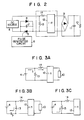
- Fig. 1 is a circuit diagram of a high voltage generator according to a first embodiment of this invention;
- Fig. 2 is a theoretic equivalent circuit diagram of Fig. 1;
- Figs. 3A to 3C are schematic equivalent circuit diagrams representing the respective operation stages of the high voltage generator of Fig. 1;
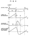
- Fig. 4 indicates signal waves appearing in the various sections of the high voltage generator of Fig. 1;
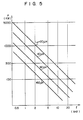
- Fig. 5 sets forth the relationship between the operating frequency and the quantity of supplied power, in case a plurality of high voltage generators are formed with substantially the same construction as that of Fig. 1, by applying a transformer having a different inductance each time;
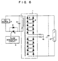
- Fig. 6 is a circuit diagram of a high voltage generator according to a second embodiment of the invention; and
- Fig. 7 is a circuit diagram of a high voltage generator according to a third embodiment of the invention.
- A description may now be made with reference to Fig. 1 of a high voltage generator according to a first embodiment of this invention. The
transformer 1 comprises aprimary winding 2 and a plurality of independentsecondary windings 3 and is rendered coreless (namely, has an air core). AD.C. source 4 is formed of a rectifying power source for rectifying and smoothing, for example, a commercial power source. Connected between a pair of output terminals of saidD.C. source 4 is a series circuit consisting of theprimary winding 2 of thetransformer 1 andGTO thyristor 5 acting as a switching element. The gate of theGTO thyristor 5 is supplied with an output control pulse from acontrol pulse generator 6. TheGTO thyristor 5 is opened and closed in response to said control pulse with a prescribed frequency of, for example, 10 KHz and a specified interval. A voltage resonance capacitor 7 is connected in parallel to the anode and cathode of theGTO thyristor 5. Adumper diode 8 is connected in inverse parallel to the anode and cathode of theGTO thyristor 5. The foregoing description represents a voltage resonance switching circuit in which theprimary winding 2 of thetransformer 1 is used as a load. - Provided on the secondary side of the
transformer 1 are a plurality of groups ofrectifier diodes 9 connected in series in the same polar direction. A plurality ofsecondary windings 3 are respectively connected between a junction of every two adjacent diodes constituting one group and a junction of every two corresponding adjacent diodes constituting another adjacent group. In this case, each secondary winding has a polarity opposite to that of the adjacent secondary winding, as indicated by a dot "." attached to the respective secondary windings. Thus, all the rectifier diodes and secondary windings jointly constitute a ladder-shaped circuit. The rectifier diodes collectively constitute a rectification circuit which eventually adds up all the output currents from the plural secondary windings in the direction of the same polarity and performs full-wave rectification. AnX-ray tube 10 is connected to said rectification circuit as a high voltage and high power load. The capacitor 11 shown in Fig. 1 represents a stray capacitive component remaining in a cable through which power is supplied from thetransformer 1 to theX-ray tube 10, and acts as a smoothing capacitor for high frequency power. - Referring to the equivalent circuit of Fig. 2 corresponding to the high voltage generating circuit of Fig. 1, the
coreless transformer 1 is equivalently constituted by anideal transformer 12,exciting inductance 13, andleakage inductance 14 prevailing between theprimary winding 2 andsecondary winding 3. - Now let it be assumed in the above-mentioned arrangement of the subject high voltage generator that the
GTO thyristor 5 is operated by a control pulse having such a wave as shown in Fig. 4; theGTO thyristor 5 is opened and closed for a prescribed period T, in which thethyristor 5 is rendered conducting for a specified period Ton, showing the stabilized circuit condition of the subject high voltage generator; theGTO thyristor 5 acts as an ideal switch which indicates no resistance when rendered conducting, and presents an infinite resistance when rendered nonconducting; and the condition of voltage resonance is mainly defined by the voltage resonance capacitance 7 andleakage inductance 14. A description may now be made of the operation of the subject high voltage generator on the basis of the above-mentioned assumption. As seen from the waveform of the control pulse shown in Fig. 4, theGTO thyristor 5 fails to retain a state of saturated conduction, unless a gate current always runs through saidGTO thyristor 5, and indicates a slight time lag (a storage period Ts) between the point of time at which a reverse bias nonconducting pulse is issued and the point of time at which theGTO thyristor 5 is rendered nonconductive. As used herein, theleakage inductance 14 is defined to mean an inductance as viewed from the primary side of thetransformer 1 when thesecondary winding 3 thereof is short-circuited. - When the
GTO thyristor 5 is rendered conductive for a period Ton (t0 to t1), then the resultant equivalent circuit presents such an arrangement as shown in Fig. 3A. Theexciting inductance 13 of thetransformer 1 appears between both output terminals of theD.C. source 4. At this time, theideal transformer 12 is connected to the prescribed one of the two output terminals of theD.C. source 4. Now let it be assumed that Lp represents the value of theexciting inductance 13; Le denotes the value of theleakage inductance 14; Ein shows the voltage of theD.C. source 4; and Eout indicates the average voltage of a power supplied to theX-ray tube 10. Then, the current ic running through theGTO thyristor 5 during the above-mentioned period may be expressed as follows:
transformer 1 bears to those of the secondary winding thereof, namely, the transformation ratio of theideal transformer 12 of Fig. 2. During the aforementioned period, the current ic conducted through theGTO thyristor 5 linearly increases as indicated by the current waveform of Fig. 4. - During the subsequent period (t1 to t2) which extends between the point of time at which the
GTO thyristor 5 is rendered nonconductive and the point of time at which thediode 8 is rendered conducting, the equivalent circuit shows the arrangement of Fig. 3B. Thus, the current flowing through theexciting inductance 13 and the current conducted through theleakage inductance 14, that is, an inertial current,_are brought into the capacitor 7 for its charge. Consequently, the terminal voltage of the capacitor 7, namely, a voltage VC impressed across both terminals of theGTO thyristor 5 increases, while delineating a resonance as shown in Fig. 4. The voltage reaches a maximum level defined by the condition of resonance and later drops. The terminal voltage of the capacitor 7 tends to have a negative value, indicated by a broken line in Fig. 4, by the action of resonance after the terminal voltage VC again falls to zero at point of time t2. At this time, however, thediode 8 is rendered conductive by the forward bias. Therefore, during the period Td (t2 to t3) which lapses before theGTO thyristor 5 is again rendered conductive, the terminal voltage VC is retained at zero. An equivalent circuit during the above-mentioned period presents the arrangement of Fig. 3C. The inertial current il passing through theexciting inductance 13 retains a limited negative value as shown in Fig. 4, even when the terminal voltage VC of the capacitor 7 falls to zero, and flows to the D.C. source through thediode 8. The circuit of a high voltage generator embodying this invention is designed in such a manner that, as shown in Fig. 4, the inertial current il delineates a waveform representing its running course by which said inertial current il first falls to the negative side as mentioned above, and then regains a zero level at the termination of a switching period T, namely, in the proximity of the starting point of the succeeding switching period (when the switchingelement 5 is rendered conductive a second time). To realize the above-mentioned circuit arrangement, it is fundamentally advised to prescribe the constants of the various circuits. The high voltage generator of this invention not only involves said advised consideration but also carries out a self- stabilizing function. Therefore, same displacement of timing, from the point of time at which the inertial current il regains a zero level, is automatically corrected by the circuit itself, which therefore tends to be stabilized, as shown in Fig. 4. - A description may now be made of the magnitude of the power which the subject high voltage generator supplies to the
load 10. As seen from Fig. 4, the magnitude of said power is defined by the power Pin correspnding to a current supplied during the period Ton (t0 to t1), that is, the power supplied from thepower source 4, and a return power Pret indicated by a current brought back to thepower source 4. Therefore, the net power Pout supplied from thepower source 4 to theload 10 is expressed as follows: -

- Now let it be assumed that a current il returned to the
power source 4 during a period Td (t2 to t3) is regarded as a current ic flowing back through theGTO thyristor 5. Then, the above-mentioned net transmitted power may be expressed by the following equation:
- As seen from the above equation, it is very effective to reduce the value Lp of the
exciting inductance 13 and the value Le of theleakage inductance 14 for the object of increasing the transmitted power. In this connection, it will be noted that the above-mentioned inductance values Lp, Le primarily depend on the winding construction of thetransformer 1. - A high voltage-generator embodying this invention offers the advantages that the application of the
coreless transformer 1 enables not only the size of thetransformer 1, and consequently the whole high voltage generator, but also the inductance values Lp, Le to be reduced, ensuring the effective transmission of a large power. Saidcoreless transformer 1 is also improved in responsibility, broadening the response frequency band and facilitating the insulation of high voltage; consequently, it is possible to eliminate the so-called coreloss of thetransformer 1 and resolve various problems arising from, for example, magnetic saturation. Moreover, the high frequency switching operation and the miniaturization of the high voltage generator can be promoted. The application of a coreless transformer generally tends to be accompanied with the drawback that a magnetic connection between the primary and secondary windings tends to be more weakened than when a core transformer is used. As described above, however, thecoreless transformer 1 of the subject high voltage generator is constructed by dividing the secondary winding intosections 3. In this case, the sections of the secondary winding 3 of thecoreless transformer 1 are wound about the outer periphery and/or the inner periphery of the primary winding 2. A good electromagnetic bonding is realized between both primary andsecondary windings coreless transformer 1 gives rise to substantially no decline in the electromagnetic bonding. - The present inventors manufactured four samples of the
coreless transformer 1 whose Lp values, respectively indicated 20 pH, 40 pH, 80 pH and 160 µH under the condition of Le=0.5 Lp. A test was made of the high voltage generators embodying this invention, which respectively involved said four samples of thecoreless transformer 1. Determination was made of the relationship between the operation frquency f and the quantity Pout of a supplied power which was observed under the condition of:


- As a result, the relationship indicated in Fig. 5 was obtained. Fig. 5 proves that when a
transformer 1 in which Lp=160 pH results, is applied to produce a power Pout of for example, 300 KW, it is advised to set the operation frequency at 0.96 KHz. In the case of a transformer of Lp=80 µH, the operation frequency should advisably be set at 1.82 KHz. In the case of a transformer of Lp=40 pH, the operation frequency should advisably be set at 3.56 KHz. Finally, in the case of a transformer of Lp=20 pH, the operation frequency should preferably be set at 7.4 KHz. The result of the above-mentioned determination means that if the subject high voltage generator is provided with acoreless transformer 1 which enables the Lp of theexciting inductance 13 to be set at 20 to 30 pH, said generator can be operated at a higher frequency than, for example, 5 KHz even when power as large as 100 KW is transmitted. In other words, when a power of hundreds of kilowatts is transmitted with the high voltage generator operated at a high frequency of several KHz units, it is necessary to apply atransformer 1 of Lp=20to 30 uH. The high voltage generator of this invention, which involves the aforementioned coreless transformer, can attain the above-mentioned object. - As compared with the inductance of an air core (coreless) coil, the conventional transformer, which involves a core consisting of laminated silicon steel plates and in which the core magnetic permeability is larger than 1, indicates a larger inductance. When 30 turns of a wire are wound about a bobbin having a diameter of, for example, 60 mm, a coreless coil has an inductance as large as 40 pH. When, therefore, such a coil involves a core prepared from the above-mentioned laminated silicon steel plates, the resultant inductance is greatly increased.
- As mentioned above, a high voltage generator embodying this invention, which involves a
coreless transformer 1, offers the advantages that thetransformer 1 can be miniaturized, and the generator can be operated at a high frequency, ensuring the effective transmission of a large volume of power. - The operation frequency of the subject high voltage generator, the inductance of the
transformer 1 and the ratio which the turns of the primary winding of saidtransformer 1 bear to those of the secondary winding thereof are determined in accordance with the required specification. The power supply to a load can be controlled by varying either the period of a control pulse issued from thecontrol pulse generator 6 to theGTO thyristor 5 or the pulse width (the timing in which theGTO thyristor 5 is intermittently rendered conducting), or both factors. Obviously, the high voltage generator embodying this invention which is constructed as described above is applicable as a power source for any other load than theX-ray tube 10. The switch element of the subject high voltage generator can be provided not only by theaforementioned GTO thyristor 5, but also by the so-called giant transistor, thyristor or any other electronic switch element having the same control function as the aforementioned elements. When, however, an electronic switch element, for example, a thyristor having no self-extinguishing function, is applied, it is of course necessary to provide an extinguishing circuit interlockingly operative with thecontrol pulse generator 6 forthe purpose of effecting extinction. - A second embodiment of this invention shown in Fig. 6 comprises a voltage resonance circuit constructed by connecting a
resonance capacitor 21 in parallel to the primary winding of thetransformer 1. The arrangement of Fig. 6 is substantially equivalent to that of Fig. 1 with respect to a high frequency. A description may now be made, with reference to Fig. 7, of a high voltage generator according to a third embodiment of this invention. Athyristor 22 acting as an auxiliary switching element is connected in series to the resonance capacitor 7 between the primary winding 2 of thetransformer 1 and said resonance capacitor 7 shown in Fig. 1. Acontrol pulse generator 23 causes theGTO thyristor 5 acting as a main switch to be intermittently operated for a prescribed period in a prescribed time, thereby enabling the operating time of saidthyristor 22 to be controlled as desired, thus ensuring the control of the power magnitude supplied to a load, for example, theX-ray tube 10. Thethyristor 22 acting as an auxiliary switching element controls the recharge of the resonance capacitor 7 during the resonance mode, thereby ensuring the control of an output power over a broad range.
Claims (8)
Applications Claiming Priority (2)
| Application Number | Priority Date | Filing Date | Title |
|---|---|---|---|
| JP58177376A JPS6070968A (en) | 1983-09-26 | 1983-09-26 | High voltage generator |
| JP177376/83 | 1983-09-26 |
Publications (3)
| Publication Number | Publication Date |
|---|---|
| EP0141985A1 EP0141985A1 (en) | 1985-05-22 |
| EP0141985B1 true EP0141985B1 (en) | 1987-12-09 |
| EP0141985B2 EP0141985B2 (en) | 1992-08-05 |
Family
ID=16029858
Family Applications (1)
| Application Number | Title | Priority Date | Filing Date |
|---|---|---|---|
| EP84111492A Expired EP0141985B2 (en) | 1983-09-26 | 1984-09-26 | High voltage generator |
Country Status (4)
| Country | Link |
|---|---|
| US (1) | US4725938A (en) |
| EP (1) | EP0141985B2 (en) |
| JP (1) | JPS6070968A (en) |
| DE (1) | DE3468080D1 (en) |
Cited By (3)
| Publication number | Priority date | Publication date | Assignee | Title |
|---|---|---|---|---|
| EP0307057A1 (en) * | 1987-09-07 | 1989-03-15 | Alcatel Nederland B.V. | Energy convertor |
| EP0556134A2 (en) * | 1992-02-14 | 1993-08-18 | Cableco | Control device for regulating current intensity in a load |
| EP0684688A1 (en) | 1994-05-27 | 1995-11-29 | Philips Patentverwaltung GmbH | Power generator with a transformer |
Families Citing this family (15)
| Publication number | Priority date | Publication date | Assignee | Title |
|---|---|---|---|---|
| JPS6081813A (en) * | 1983-10-12 | 1985-05-09 | Toshiba Corp | High tension transformer |
| WO1993023914A1 (en) * | 1992-05-11 | 1993-11-25 | Electric Power Research Institute | Harmonic blocking converter system |
| WO1993023913A1 (en) * | 1992-05-11 | 1993-11-25 | Electric Power Research Institute | Optimized high power voltage sourced inverter system |
| US5519312A (en) * | 1993-11-29 | 1996-05-21 | Alfred University | Hybrid system of fuel cell and superconducting magnetic energy storage device |
| US7768371B2 (en) | 1998-02-05 | 2010-08-03 | City University Of Hong Kong | Coreless printed-circuit-board (PCB) transformers and operating techniques therefor |
| CA2371788A1 (en) | 1999-05-25 | 2000-11-30 | Dentsply International Inc. | Dental x-ray apparatus |
| DE10010278A1 (en) * | 2000-03-02 | 2001-09-06 | Peter Mandl | Circuit arrangement for rectifier with variable output parameters e.g. for starting DC motor, has terminals of AC sources, except the star-point terminals with multiphase systems |
| US6765987B2 (en) * | 2001-03-15 | 2004-07-20 | Safe Food Technologies, Inc. | Resonant plasma x-ray source |
| DE102004001478B4 (en) * | 2004-01-09 | 2015-09-24 | Semikron Elektronik Gmbh & Co. Kg | Converter circuit arrangement for converting an alternating voltage into a high-voltage direct voltage |
| EP1860838B1 (en) * | 2006-05-24 | 2013-08-14 | Infineon Technologies AG | Data transmission using phase modulation over two signal paths |
| DE102007032808A1 (en) * | 2007-07-13 | 2009-01-15 | Siemens Ag | Potential control in high-voltage devices |
| US9800133B2 (en) * | 2016-03-22 | 2017-10-24 | Infineon Technologies Ag | Active common mode cancellation |
| WO2018087145A1 (en) | 2016-11-08 | 2018-05-17 | Koninklijke Philips N.V. | Inductor for high frequency and high power applications |
| US11103207B1 (en) * | 2017-12-28 | 2021-08-31 | Radiation Monitorng Devices, Inc. | Double-pulsed X-ray source and applications |
| US11901153B2 (en) * | 2021-03-05 | 2024-02-13 | Pct Ebeam And Integration, Llc | X-ray machine |
Family Cites Families (11)
| Publication number | Priority date | Publication date | Assignee | Title |
|---|---|---|---|---|
| US3197691A (en) * | 1962-01-02 | 1965-07-27 | Gen Electric | Regulated power supply |
| US3419786A (en) * | 1966-12-27 | 1968-12-31 | Westinghouse Electric Corp | Electrical converter apparatus for rectifying and adding a plurality of a.c. voltages |
| DE2750544A1 (en) | 1977-11-11 | 1979-05-17 | Siemens Ag | ROYAL DIAGNOSTIC GENERATOR WITH AN INVERTER FEEDING ITS HIGH VOLTAGE TRANSFORMER |
| US4318164A (en) * | 1979-03-15 | 1982-03-02 | Tokyo Shibaura Denki Kabushiki Kaisha | High frequency switching circuit having preselected parameters to reduce power dissipation therein |
| JPS56150968A (en) * | 1980-04-22 | 1981-11-21 | Toshiba Corp | Switching circuit of single end high frequency |
| US4339704A (en) * | 1980-07-07 | 1982-07-13 | General Electric Company | Series parallel transition for power supply |
| US4386395A (en) * | 1980-12-19 | 1983-05-31 | Webster Electric Company, Inc. | Power supply for electrostatic apparatus |
| JPS57138866A (en) * | 1981-02-17 | 1982-08-27 | Toshiba Corp | Voltage resonance type high frequency switching circuit |
| US4366532A (en) * | 1981-05-11 | 1982-12-28 | Westinghouse Electric Corp. | AC/DC or DC/AC Converter system with improved AC-line harmonic reduction |
| JPS5947976A (en) * | 1982-09-08 | 1984-03-17 | Toshiba Corp | High voltage generator circuit |
| US4480298A (en) * | 1983-01-25 | 1984-10-30 | Westinghouse Electric Corp. | Multiple output DC-to-DC voltage converter apparatus |
-
1983
- 1983-09-26 JP JP58177376A patent/JPS6070968A/en active Granted
-
1984
- 1984-09-26 DE DE8484111492T patent/DE3468080D1/en not_active Expired
- 1984-09-26 EP EP84111492A patent/EP0141985B2/en not_active Expired
-
1986
- 1986-09-29 US US06/912,657 patent/US4725938A/en not_active Expired - Lifetime
Cited By (5)
| Publication number | Priority date | Publication date | Assignee | Title |
|---|---|---|---|---|
| EP0307057A1 (en) * | 1987-09-07 | 1989-03-15 | Alcatel Nederland B.V. | Energy convertor |
| EP0556134A2 (en) * | 1992-02-14 | 1993-08-18 | Cableco | Control device for regulating current intensity in a load |
| EP0556134A3 (en) * | 1992-02-14 | 1993-10-06 | Cableco | Control device for regulating current intensity in a load |
| EP0684688A1 (en) | 1994-05-27 | 1995-11-29 | Philips Patentverwaltung GmbH | Power generator with a transformer |
| US5586017A (en) * | 1994-05-27 | 1996-12-17 | U.S. Philips Corporation | Power generator comprising a transformer |
Also Published As
| Publication number | Publication date |
|---|---|
| DE3468080D1 (en) | 1988-01-21 |
| EP0141985A1 (en) | 1985-05-22 |
| EP0141985B2 (en) | 1992-08-05 |
| US4725938A (en) | 1988-02-16 |
| JPH0515151B2 (en) | 1993-02-26 |
| JPS6070968A (en) | 1985-04-22 |
Similar Documents
| Publication | Publication Date | Title |
|---|---|---|
| EP0141985B1 (en) | High voltage generator | |
| AU612118B2 (en) | High voltage power supply particularly adapted for a TWT | |
| US4914561A (en) | Dual transformer device for power converters | |
| US4525774A (en) | Regulated AC-DC converter having saturation inductance in resonant circuit | |
| EP0610158B1 (en) | Fixed frequency converter switching at zero voltage | |
| US5438497A (en) | Tertiary side resonant DC/DC converter | |
| US5459650A (en) | Power supply circuit | |
| EP0291120B1 (en) | A regulated high frequency power supply | |
| US5563775A (en) | Full bridge phase displaced resonant transition circuit for obtaining constant resonant transition current from 0° phase angle to 180° phase angle | |
| US4417153A (en) | High frequency switching circuit | |
| EP0064483B1 (en) | High voltage converter | |
| US5317496A (en) | DC/DC-converter with a primary circuit and at least one secondary circuit tuned as individually oscillatory circuits | |
| US4276587A (en) | DC to DC Converter | |
| US6282103B1 (en) | Switching power supply using an inductor device to prevent harmonic current generation | |
| DE19824409A1 (en) | AC-DC converter | |
| US4530043A (en) | DC switching voltage converter for multiplying an input DC voltage without increasing the switching conduction period | |
| US5317494A (en) | Power supply circuit utilizing voltage and current resonance for reducing switching loss | |
| US4435747A (en) | High voltage supply system for medical equipment | |
| US4401902A (en) | High frequency switching circuit | |
| US5327334A (en) | Zero current switching DC-DC converter incorporating a tapped resonant inductor | |
| US4945464A (en) | High voltage DC power supply | |
| EP0146225A1 (en) | An inverter in an x-ray generator | |
| US4660134A (en) | DC-DC converter with chopping switch and transformer | |
| JPH0974741A (en) | Converter | |
| EP0534379A2 (en) | Power supply circuit |
Legal Events
| Date | Code | Title | Description |
|---|---|---|---|
| PUAI | Public reference made under article 153(3) epc to a published international application that has entered the european phase |
Free format text: ORIGINAL CODE: 0009012 |
|
| 17P | Request for examination filed |
Effective date: 19840926 |
|
| AK | Designated contracting states |
Designated state(s): DE FR GB NL |
|
| 17Q | First examination report despatched |
Effective date: 19860425 |
|
| GRAA | (expected) grant |
Free format text: ORIGINAL CODE: 0009210 |
|
| AK | Designated contracting states |
Kind code of ref document: B1 Designated state(s): DE FR NL |
|
| REF | Corresponds to: |
Ref document number: 3468080 Country of ref document: DE Date of ref document: 19880121 |
|
| ET | Fr: translation filed | ||
| PLBI | Opposition filed |
Free format text: ORIGINAL CODE: 0009260 |
|
| 26 | Opposition filed |
Opponent name: SIEMENS AKTIENGESELLSCHAFT, BERLIN UND MUENCHEN Effective date: 19880425 |
|
| NLR1 | Nl: opposition has been filed with the epo |
Opponent name: SIEMENS AKTIENGESELLSCHAFT |
|
| PUAH | Patent maintained in amended form |
Free format text: ORIGINAL CODE: 0009272 |
|
| STAA | Information on the status of an ep patent application or granted ep patent |
Free format text: STATUS: PATENT MAINTAINED AS AMENDED |
|
| 27A | Patent maintained in amended form |
Effective date: 19920805 |
|
| AK | Designated contracting states |
Kind code of ref document: B2 Designated state(s): DE FR NL |
|
| NLR2 | Nl: decision of opposition | ||
| NLR3 | Nl: receipt of modified translations in the netherlands language after an opposition procedure | ||
| ET3 | Fr: translation filed ** decision concerning opposition | ||
| PGFP | Annual fee paid to national office [announced via postgrant information from national office to epo] |
Ref country code: FR Payment date: 19990909 Year of fee payment: 16 |
|
| PGFP | Annual fee paid to national office [announced via postgrant information from national office to epo] |
Ref country code: DE Payment date: 19990927 Year of fee payment: 16 |
|
| PGFP | Annual fee paid to national office [announced via postgrant information from national office to epo] |
Ref country code: NL Payment date: 19990930 Year of fee payment: 16 |
|
| PG25 | Lapsed in a contracting state [announced via postgrant information from national office to epo] |
Ref country code: NL Free format text: LAPSE BECAUSE OF NON-PAYMENT OF DUE FEES Effective date: 20010401 |
|
| PG25 | Lapsed in a contracting state [announced via postgrant information from national office to epo] |
Ref country code: FR Free format text: LAPSE BECAUSE OF NON-PAYMENT OF DUE FEES Effective date: 20010531 |
|
| NLV4 | Nl: lapsed or anulled due to non-payment of the annual fee |
Effective date: 20010401 |
|
| PG25 | Lapsed in a contracting state [announced via postgrant information from national office to epo] |
Ref country code: DE Free format text: LAPSE BECAUSE OF NON-PAYMENT OF DUE FEES Effective date: 20010601 |
|
| REG | Reference to a national code |
Ref country code: FR Ref legal event code: ST |
|
| APAH | Appeal reference modified |
Free format text: ORIGINAL CODE: EPIDOSCREFNO |