EP0144437B1 - Rheometer - Google Patents
Rheometer Download PDFInfo
- Publication number
- EP0144437B1 EP0144437B1 EP84902051A EP84902051A EP0144437B1 EP 0144437 B1 EP0144437 B1 EP 0144437B1 EP 84902051 A EP84902051 A EP 84902051A EP 84902051 A EP84902051 A EP 84902051A EP 0144437 B1 EP0144437 B1 EP 0144437B1
- Authority
- EP
- European Patent Office
- Prior art keywords
- piece
- movable
- displacement
- rheometer
- sample
- Prior art date
- Legal status (The legal status is an assumption and is not a legal conclusion. Google has not performed a legal analysis and makes no representation as to the accuracy of the status listed.)
- Expired
Links
Images
Classifications
-
- G—PHYSICS
- G01—MEASURING; TESTING
- G01N—INVESTIGATING OR ANALYSING MATERIALS BY DETERMINING THEIR CHEMICAL OR PHYSICAL PROPERTIES
- G01N11/00—Investigating flow properties of materials, e.g. viscosity, plasticity; Analysing materials by determining flow properties
- G01N11/10—Investigating flow properties of materials, e.g. viscosity, plasticity; Analysing materials by determining flow properties by moving a body within the material
Definitions
- the invention relates to a viscometer, an elastometer, a viscoelastometer or a rheometer.
- rheometer a part of the movable-piece or the whole of the piece is immersed in or contacting with or fixed to a viscoelastic sample to be measured, and it makes relative motion as a sensing member to the sample.
- Force on the movable-piece is influenced by the rheological properties of the sample.
- the rheological properties of the sample are determined usually according to the relation between the force on the sensing member and the relative motion of the sensing member to the measured sample.
- the drive or support mechanism in the prior art systems involves elastic supporting elements, for example, torsion bars or plate springs, or bearing elements, for example, rotary bearings or linear sliding bearings.
- a movable-piece is plunged into the gel-like high viscoelastic sample.
- the present invention solves these serious problems in the conventional rheometers as mentioned above, and provides a rheometer and a convenient method to determine precisely the rheological properties of a sample with a very small amount of the sample covering high test frequency with simple mechanical structure.
- the present invention has merits and advantages mentioned below.
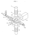
- FIG. 1 is a perspective schematic representation of the main portions of one embodiment of the present invention.
- a movable-piece 1 as a sensing member is a sphere fully or partly composed of magnetic material, for example, soft iron, and is immersed in a viscoelastic sample material 2 sealed hermetically in a sample container 3 with transparent windows.
- Magnet cores 4,5 which is winded with magnet coil 6,7 of, for example, enamelled copper wires composes a pair of electromagnet facing each other.
- a displacement measuring device 9, for example, a non-contact optoelectronic tracker detects the displacement of the image of the movable-piece 1 transmitted by a light beam from a light source 8, for example, an electric lamp.
- the sample container 3 is fixed to the free end of a bracket 10.
- the bracket 10 is a cantilever of an elastic substance, for example, phosphor bronze, and equipped with a displacement measuring device 11, for example, an electric resistance wire strain gauge which detects the displacement of the sample container 3.
- a magnetic plate 12 is fixed near the free end of the bracket 10, and the sample container 3 vibrates vertically in the co-axial direction between the pair of magnet cores 4,5.
- a container clump 15 is used in moving probe mode when only the movable-piece is reciprocated but the container 3 is fixed.
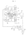
- Fig. 2 is a diagram of the electric circuit of one embodiment of the present invention.
- Driving currents are supplied to the magnet coils 6,7 by D.C. power amplifiers 16,17.
- Resistors 21,22 detects coil currents of the magnet coils 6,7 respectively.
- the servomechanism of a preferred embodiment of the present invention consists as follows.
- a displacement measuring device 9 produces a signal voltage proportional to the displacement of said movable-piece 1.
- a signal voltage which indicates position or motion to be followed is introduced by a wave generator 18.
- An operational amplifier 19 produces a signal voltage indicating the dislocation of said movable-piece 1 at the instance with a reference standard signal voltage indicating an intended position, and produces a differential signal voltage, which is fed into D.C. power amplifiers 16,17, and they supply drive currents to the magnet coils 7,8, and reduce deviation of the movable-piece 1 off from intended position.
- a compensation circuit 20 consists of, for example, P(proportional), l(integral), D(differential) circuits and provides quick response and good stability of the servo-system.
- any type of means for non-contact displacement measurement can be employed.
- other devices can be used such as conventional devices for displacement measurement employing photoelectric principles, for example a photocell and a photodiode, conventional devices using radiant rays, electromagnetic waves, for example, using X-rays or gamma-rays and ultrasonic waves.
- a contact manner For sensing of the position of the sample container 3, comparatively bulky methods in a contact manner can be also applied.
- They are an electromagnetic device, for example, a pick-up coil or a differential transformer, an electrocapaci- tance device and an electric resistance wire strain gauge.
- a sphere is preferable, because it is symmetrical in every direction, mechanically strong, easy to be manufactured and convenient to analyse as a theoretical model.
- parallel motion of a needle, a strip or a plate, or rotational motion of a column, a cylinder, a cone or a disc may be also appliable.
- a moment is produced by magnetic drive unit with its magnetic poles placed in a tangential direction on a magnetic tip to the rim of the disc-shaped movable-piece.
- Another method is a circular arrangement of electric field magnets around the movable-piece 1, which generates rotational magnetic field and produces a moment by an induction effect.
- Those are well known conventional methods used in electric rotary machines. Detection of the position or motion of a movable-piece is also capable at the same point where the magnetic force works.
- supplementary supporting elements for example rotary bearings such as a magnetic bearing, a fluid bearing or a mechanical bearing may be additionary used.
- rotary bearings such as a magnetic bearing, a fluid bearing or a mechanical bearing
- the movable-piece 1 may be attached to the sample material 2.
- the movable-piece 1 gives external force on the sample material 1 and produces tension, compression, bending, shearing or torsion in the material. And the relation between the external force and the deformation of the sample yields rheological properties of the sample.
- a signal generator 18 may be so adjusted as to produce the same signal voltage as the output voltage from a displacement measuring device 9 to be expected.
- the embodiment of the invention can be used in either of the two measuring modes, which are a moving container mode and a moving probe mode, by selecting among them.
- a moving container mode the movable-piece 1 is held stationary at the fixed position and a vibrator coil 13 moves the sample container 3.
- a moving probe mode the sample container 3 is held stationary by a container clump 15 and a movable-piece 1 moves according to the signal from a wave generator 18.
- the viscoelastic values of a sample material 2 is determined according to the magnetic force on a movable-piece 1 and relative motion between the movable-piece 1 and the sample material 2.
- the magnetic force can be estimated using voltage drop across resistors 21,22 for a measure of coil currents, but practically it is convenient to perform calibration of the magnetic force by either of the gravitational acceleration on the movable-piece 1 or sinusoidal oscillation of the movable-piece 1 in a Newtonian fluid of known viscosity using the same values for the driving currents.
- a relative displacement between a movable-piece 1 and a sample material 2 is measured in a moving container mode according to the displacement of the sample container 3, and in a moving probe mode according to the motion of the movable-piece 1, that is, according to an output signal voltage from the displacement measuring device 9 respectively.
- the change of magnetic force may be assumed to be proportional to the change of the coil current, when the test frequency is not so high, where
- Complex modulus and viscosity is calculated, for example, using a sphere as a movable-piece 1 and simple oscillation displacement to a viscoelastic material.
- the magnetic force is plotted in horizontal axis and the displacement of the movable-piece 1 is plotted vertical axis on an oscilloscope.
- the magnetic force is measured by current through resistor 22, and the displacement is measured by the displacement measuring device 9 and the Lissadous-loop of them on an oscilloscope results in an ellipse.
- the phase lag of displacement to magnetic force is determined according to the shape of the ellipse.
- the present invention is valuable as an apparatus for rheological measurement and its: simple mechanical structure yields easy manufacture of it and convenient operation. It is useful in such fields as rheological, especially biorheological studies where only a very small amount of sample is available, and in such fields as examination, usage and production of rheological material, because of convenient operation and quick measurement.
Abstract
Description
- The invention relates to a viscometer, an elastometer, a viscoelastometer or a rheometer. Hereafterthey all are called rheometer as a general term. In a movable-piece type of rheometer, a part of the movable-piece or the whole of the piece is immersed in or contacting with or fixed to a viscoelastic sample to be measured, and it makes relative motion as a sensing member to the sample. Force on the movable-piece is influenced by the rheological properties of the sample. The rheological properties of the sample are determined usually according to the relation between the force on the sensing member and the relative motion of the sensing member to the measured sample.
- The drive or support mechanism in the prior art systems involves elastic supporting elements, for example, torsion bars or plate springs, or bearing elements, for example, rotary bearings or linear sliding bearings.
- In some types of conventional movable-piece rheometer a movable-piece is plunged into the gel-like high viscoelastic sample.
- But such a mechanical support structure as an elastic support structure or a bearing has complicated structure and is easily damaged. They suffer inconvenient change of samples. Moreover they have difficulty in measuring a small amount of sample because it is impossible to manufacture a very small dimension of movable-piece and it is difficult to measure at high test frequencies. The movable-piece which is plunged into a sample is difficult in holding itself in the intended sensing position because of its gradual dislocation during measurement.
- In another prior art arrangement (US Patent 3967934 to Seitz et al), it has been proposed to suspend a movable magnetic member in a sample in a test tube, which is located between a pair of fixed internal magnets, and mounted for vertical reciprocation. A vertical movement of the member relative to the magnets, caused by a predetermined increase in viscosity of the sample, is then detected photoelectrically or electromagnetically. However in such a proposed arrangement there is a tendency for the member to move towards one of the magnets until it touches the inside wall of the test tube, so that there is no positive control over the position of the member within the test tube.
- In a further arrangement proposed by S. L. James et al (Journal of Physics E. Scientific Instruments Vol. 15 (1982) pp. 1979, 180) a magnetic member is suspended in a sample and caused to oscillate between a pair of electromagnets, the movement of the member being optically monitored. Again, however, there is no control over the precise location of the member so that it can deviate from its intended path of movement relative to the sample.
- The present invention solves these serious problems in the conventional rheometers as mentioned above, and provides a rheometer and a convenient method to determine precisely the rheological properties of a sample with a very small amount of the sample covering high test frequency with simple mechanical structure.
- According to the present invention there is provided a rheometer for measuring viscoelasticity of a sample material comprising: a sample container for holding said material, means for displacing said container, a magnetic movable-piece located in said material to serve as a displacement sensing member, an electromagnet placed adjacent said movable-piece, and means for detecting the displacement of said movable-piece, characterised by electronic servomechanism means for adjusting the displacement of said movable-piece in a non-contact manner, following a predetermined displacement, by controlling the excitation current of the electromagnet and by means for introducing a signal into said servomechanism which indicates the predetermined displacement.
- The present invention has merits and advantages mentioned below.
- (a) A rheometer of present invention has no mechanical support structure. Therefore a very small sensing-member can be manufactured. It does not suffer troublesome adjustment of the support structure. No anxiety is needed about deformation or destruction of the support structure in changing samples. It provides long mechanical life without any trouble around support structure. A movable-piece and a sample can be sealed hermetically in a disposable container cartridge. So that, the same container for storage can be used also for measurement, and it provides quick convenient change of samples without contamination of samples, repetition of measurement of the sample, and it avoids denaturalization due to evaporation, scattering of, for example, radioactive samples. Temperature control, for example, warming or cooling of a sample material is managed easily.
- (b) A very small sensing-member can be employed. Therefore, the rheometer can measure accurately a very small amount of sample. The sensing-member accurately works even at high test frequency, and it is hardly interrupted by mass effect of a movable-piece.
- (c) The movable-piece does not touch with a container wall, and is not influenced by support structure. Therefore, the rheometer accurately measures even low viscoelastic samples and even in test condition of very small viscoelastic force. Calibration of the magnetic force against the coil current is easily performed using the gravitational acceleration, and it yields good accuracy and good reproducibility of measurement.
- (d) The sensitivity of the instrument is easily regulated by changing the characteristics of the servomechanism, and the measurement covers a wide viscoelastic range from low values to high and a wide frequency range.
- Fig. 1 is a perspective schematic representation of the main portions of one preferred embodiment of the present invention.
- Fig. 2 is a diagram of the electric circuit of one preferred embodiment of the present invention.
- (Designation number and elements)
- 1: movable-piece (sensing member)
- 2: sample material
- 3: sample container
- 4,5: magnet core
- 6,7: magnet coil
- 8: light source
- 9: displacement measuring device
- 10: bracket
- 11: displacement measuring device
- 12: magnetic plate
- 13: vibrator coil
- 14: field magnet
- 15: container clump
- 16,17: D.C. power amplifier
- 18: wave generator
- 19: operational amplifier
- 20: compensation circuit
- 21,22: resistor
- Referring to the attached drawings, the details of the present invention are described below.
- Fig. 1 is a perspective schematic representation of the main portions of one embodiment of the present invention. A movable-piece 1 as a sensing member is a sphere fully or partly composed of magnetic material, for example, soft iron, and is immersed in a viscoelastic sample material 2 sealed hermetically in a
sample container 3 with transparent windows.Magnet cores magnet coil displacement measuring device 9, for example, a non-contact optoelectronic tracker detects the displacement of the image of the movable-piece 1 transmitted by a light beam from alight source 8, for example, an electric lamp. Thesample container 3 is fixed to the free end of abracket 10. Thebracket 10 is a cantilever of an elastic substance, for example, phosphor bronze, and equipped with adisplacement measuring device 11, for example, an electric resistance wire strain gauge which detects the displacement of thesample container 3. Amagnetic plate 12 is fixed near the free end of thebracket 10, and thesample container 3 vibrates vertically in the co-axial direction between the pair ofmagnet cores container clump 15 is used in moving probe mode when only the movable-piece is reciprocated but thecontainer 3 is fixed. - Fig. 2 is a diagram of the electric circuit of one embodiment of the present invention. Driving currents are supplied to the magnet coils 6,7 by
D.C. power amplifiers Resistors - In order to hold said movable-piece 1 in the same position or to put it in intended motion, the servomechanism of a preferred embodiment of the present invention consists as follows. A
displacement measuring device 9 produces a signal voltage proportional to the displacement of said movable-piece 1. A signal voltage which indicates position or motion to be followed is introduced by awave generator 18. Anoperational amplifier 19 produces a signal voltage indicating the dislocation of said movable-piece 1 at the instance with a reference standard signal voltage indicating an intended position, and produces a differential signal voltage, which is fed intoD.C. power amplifiers compensation circuit 20 consists of, for example, P(proportional), l(integral), D(differential) circuits and provides quick response and good stability of the servo-system. - As for measurement of the displacement of the movable-piece 1 or the
sample container 3, any type of means for non-contact displacement measurement can be employed. Beside the optoelectronic tracker used in said embodiment, other devices can be used such as conventional devices for displacement measurement employing photoelectric principles, for example a photocell and a photodiode, conventional devices using radiant rays, electromagnetic waves, for example, using X-rays or gamma-rays and ultrasonic waves. - For sensing of the position of the
sample container 3, comparatively bulky methods in a contact manner can be also applied. They are an electromagnetic device, for example, a pick-up coil or a differential transformer, an electrocapaci- tance device and an electric resistance wire strain gauge. - It is capable at various points in the servo-system to input the signal of the relative displacement or motion between the movable-piece 1 and the
sample container 3. Usually it is convenient to set the position or displacement directly by a reference standard voltage to anoperational amplifier 19 by awave generator 18. Another method is carried out by inputting to a servo-system a direct current component, which indicates an average position of the movable-piece 1. And an oscillatory component is fed to the system outside the servomechanism. Another methods are performed by setting the displacement of alight source 8, adisplacement measuring device 9 or asample container 3. - In high frequency oscillation, alternation of the coil current, that is, of the magnetic force lags in phase behind a supplied voltage across the magnet coils 6,7 due to a coil inductance. Therefore, basically the direct control of the coil currents is preferable from the viewpoint of characteristics of a servomechanism.
- As for the shape of the movable-piece 1, a sphere is preferable, because it is symmetrical in every direction, mechanically strong, easy to be manufactured and convenient to analyse as a theoretical model. However, parallel motion of a needle, a strip or a plate, or rotational motion of a column, a cylinder, a cone or a disc may be also appliable. In order to establish and control rotational motion of a disc-shaped movable-piece by magnetic force, a moment is produced by magnetic drive unit with its magnetic poles placed in a tangential direction on a magnetic tip to the rim of the disc-shaped movable-piece. Another method is a circular arrangement of electric field magnets around the movable-piece 1, which generates rotational magnetic field and produces a moment by an induction effect. Those are well known conventional methods used in electric rotary machines. Detection of the position or motion of a movable-piece is also capable at the same point where the magnetic force works. In this case, if preferred, supplementary supporting elements, for example rotary bearings such as a magnetic bearing, a fluid bearing or a mechanical bearing may be additionary used. Of course the elements do not spoil the advantages of the invention because they do not disturb or restrict intended relative motion.
- As for solid viscoelastic material, the movable-piece 1 may be attached to the sample material 2. In the influence of magnetic field by magnetic drive unit the movable-piece 1 gives external force on the sample material 1 and produces tension, compression, bending, shearing or torsion in the material. And the relation between the external force and the deformation of the sample yields rheological properties of the sample.
- The working mechanism of one embodiment of the invention is described hereafter. Suppose, for example, the polarity is chosen that the output signal voltage becomes positive when the movable-piece 1 makes displacement upward relative to a standard point in the view screen of the
displacement measuring device 9. In order to input a signal which indicates intended position of the movable-piece 1, asignal generator 18 may be so adjusted as to produce the same signal voltage as the output voltage from adisplacement measuring device 9 to be expected. - In measuring by a method of holding a movable-piece 1 stationary in a fixed position, referring to Fig. 2, if the movable-piece 1 locates above the intended position indicated by a
wave generator 18, the output from theoperational amplifier 19 will become positive, and driving current through themagnet coil 6 from theD.C. power amplifier 16 will increase, on the other hand driving current throughmagnet coil 7 from aD.C. power amplifier 17 will decrease consequently resulting that the movable-piece 1 will be tracted downward by magnetic force. To the contrary, if the movable-piece 1 locates below the intended position, it will be tracted upward by magnetic force. When the movable-piece 1 arrives at the intended position the output signal voltage from theoperational amplifier 19 becomes naught and the magnetic force which tracts the movable-piece 1 is not produced. - If it is desired that the movable-piece 1 moves following an intended motion, all necessary is only that a signal voltage from a
wave generator 18 varies in the same pattern as an intended motion. To perform measurement, the embodiment of the invention can be used in either of the two measuring modes, which are a moving container mode and a moving probe mode, by selecting among them. In a moving container mode, the movable-piece 1 is held stationary at the fixed position and avibrator coil 13 moves thesample container 3. Instead, in a moving probe mode, thesample container 3 is held stationary by acontainer clump 15 and a movable-piece 1 moves according to the signal from awave generator 18. - The viscoelastic values of a sample material 2 is determined according to the magnetic force on a movable-piece 1 and relative motion between the movable-piece 1 and the sample material 2. Although the magnetic force can be estimated using voltage drop across
resistors - A relative displacement between a movable-piece 1 and a sample material 2 is measured in a moving container mode according to the displacement of the
sample container 3, and in a moving probe mode according to the motion of the movable-piece 1, that is, according to an output signal voltage from thedisplacement measuring device 9 respectively. - Calculating of the viscoelasticity is performed as follows. Firstly described is the calibration of magnetic force against a coil current by standard of the gravitational acceleration. Suppose that the co-axis between the
magnet cores operational amplifier 19 is switched off to naught, thedrive currents wave generator 18 so that the movable-piece 1 may be suspended exactly in the center of the gap between themagnet cores -


- io: current through
coil 6 without any load - ii: current through
coil 6 with gravitational load - i2: current through
coil 7 with gravitional load - iG: current shift by gravitational load
- i": current through
coil 7 in measurement - r: radius of a sphere
- ps: density of a sphere
- pt: density of a sample material
- g: gravitational acceleration
- F: magnetic force
- Complex modulus and viscosity is calculated, for example, using a sphere as a movable-piece 1 and simple oscillation displacement to a viscoelastic material. When recording the relation between the force on a movable-piece 1 and relative motion, for example, the magnetic force is plotted in horizontal axis and the displacement of the movable-piece 1 is plotted vertical axis on an oscilloscope. The magnetic force is measured by current through
resistor 22, and the displacement is measured by thedisplacement measuring device 9 and the Lissadous-loop of them on an oscilloscope results in an ellipse. The phase lag of displacement to magnetic force is determined according to the shape of the ellipse. -
sin 6=(major axis * minor axis of ellipse)/(area of rectangle whose side is parallel to the horizontal axis, circumscribed to ellipse) Complex modulus is defined by


- G*: complex modulus (complex elasticty)
- G': storage modulus (dynamic elasticity)
- G": loss modulus
- G: absolute value of complex modulus
- F: amplitude of magnetic force oscillation
- X: amplitude of displacement oscillation
- n: viscosity
- e: base of natural logarithm
- i: imaginary unit
- ω: angular frequency
- 5: phase tag
- t: time
- The present invention is valuable as an apparatus for rheological measurement and its: simple mechanical structure yields easy manufacture of it and convenient operation. It is useful in such fields as rheological, especially biorheological studies where only a very small amount of sample is available, and in such fields as examination, usage and production of rheological material, because of convenient operation and quick measurement.
Claims (5)
Priority Applications (1)
| Application Number | Priority Date | Filing Date | Title |
|---|---|---|---|
| AT84902051T ATE36412T1 (en) | 1983-05-31 | 1984-05-14 | RHEOMETER. |
Applications Claiming Priority (4)
| Application Number | Priority Date | Filing Date | Title |
|---|---|---|---|
| JP96700/83 | 1983-05-31 | ||
| JP9670083A JPS59221639A (en) | 1983-05-31 | 1983-05-31 | Viscometer |
| JP3483884A JPS60178336A (en) | 1984-02-25 | 1984-02-25 | Viscoelasticity meter |
| JP34838/84 | 1984-02-25 |
Publications (3)
| Publication Number | Publication Date |
|---|---|
| EP0144437A1 EP0144437A1 (en) | 1985-06-19 |
| EP0144437A4 EP0144437A4 (en) | 1985-10-14 |
| EP0144437B1 true EP0144437B1 (en) | 1988-08-10 |
Family
ID=26373702
Family Applications (1)
| Application Number | Title | Priority Date | Filing Date |
|---|---|---|---|
| EP84902051A Expired EP0144437B1 (en) | 1983-05-31 | 1984-05-14 | Rheometer |
Country Status (4)
| Country | Link |
|---|---|
| US (1) | US4602501A (en) |
| EP (1) | EP0144437B1 (en) |
| DE (1) | DE3473351D1 (en) |
| WO (1) | WO1984004812A1 (en) |
Families Citing this family (36)
| Publication number | Priority date | Publication date | Assignee | Title |
|---|---|---|---|---|
| GB8525255D0 (en) * | 1985-10-14 | 1985-11-20 | Ravenfield Designs Ltd | Rheometer |
| US4794788A (en) * | 1987-10-05 | 1989-01-03 | Monsanto Company | Method and apparatus for rheological testing |
| DE3800474A1 (en) * | 1988-01-11 | 1989-07-20 | Basf Lacke & Farben | METHOD AND DEVICE FOR MEASURING THE VISCOSITY OF SUBSTANCES |
| JPH02157655A (en) * | 1988-12-09 | 1990-06-18 | Seiko Instr Inc | Reaction vessel |
| SE501809C2 (en) * | 1992-10-05 | 1995-05-22 | Lund Medicinsk Reologi Ab | Ways to measure rheological properties and rheometer for implementation of the method |
| US5365778A (en) * | 1994-01-28 | 1994-11-22 | The University Of Chicago | Method for measuring liquid viscosity and ultrasonic viscometer |
| AUPM517894A0 (en) * | 1994-04-19 | 1994-05-12 | Commonwealth Scientific And Industrial Research Organisation | Viscosity measurement device |
| IL114494A0 (en) * | 1995-07-06 | 1995-11-27 | Te Eni Moshe | System and method for controlling concrete production |
| DE19733114C2 (en) * | 1997-07-31 | 1999-08-05 | Max Planck Gesellschaft | Method and device for recording rheological material properties |
| US6227039B1 (en) * | 1998-01-06 | 2001-05-08 | Moshe Te'eni | System and method for controlling concrete production |
| US6393898B1 (en) | 2000-05-25 | 2002-05-28 | Symyx Technologies, Inc. | High throughput viscometer and method of using same |
| US6664067B1 (en) | 2000-05-26 | 2003-12-16 | Symyx Technologies, Inc. | Instrument for high throughput measurement of material physical properties and method of using same |
| US6484567B1 (en) | 2000-08-03 | 2002-11-26 | Symyx Technologies, Inc. | Rheometer for rapidly measuring small quantity samples |
| SE0100918D0 (en) * | 2001-03-16 | 2001-03-16 | Global Hemostasis Inst Mgr Ab | Rod provided with channel |
| US6857309B2 (en) | 2001-08-24 | 2005-02-22 | Symyx Technologies, Inc. | High throughput mechanical rapid serial property testing of materials libraries |
| US6650102B2 (en) | 2001-08-24 | 2003-11-18 | Symyx Technologies, Inc. | High throughput mechanical property testing of materials libraries using a piezoelectric |
| US6690179B2 (en) * | 2001-08-24 | 2004-02-10 | Symyx Technologies, Inc. | High throughput mechanical property testing of materials libraries using capacitance |
| US6769292B2 (en) | 2001-08-24 | 2004-08-03 | Symyx Technologies, Inc | High throughput rheological testing of materials |
| US6837115B2 (en) * | 2001-08-24 | 2005-01-04 | Symyx Technologies, Inc. | High throughput mechanical rapid serial property testing of materials libraries |
| US6860148B2 (en) | 2001-08-24 | 2005-03-01 | Symyx Technologies, Inc. | High throughput fabric handle screening |
| US6772642B2 (en) | 2001-08-24 | 2004-08-10 | Damian A. Hajduk | High throughput mechanical property and bulge testing of materials libraries |
| US6736017B2 (en) | 2001-08-24 | 2004-05-18 | Symyx Technologies, Inc. | High throughput mechanical rapid serial property testing of materials libraries |
| US20030055587A1 (en) * | 2001-09-17 | 2003-03-20 | Symyx Technologies, Inc. | Rapid throughput surface topographical analysis |
| US7013709B2 (en) * | 2002-01-31 | 2006-03-21 | Symyx Technologies, Inc. | High throughput preparation and analysis of plastically shaped material samples |
| US20030203500A1 (en) * | 2002-04-26 | 2003-10-30 | Symyx Technologies, Inc. | High throughput testing of fluid samples using an electric field |
| US7112443B2 (en) * | 2002-10-18 | 2006-09-26 | Symyx Technologies, Inc. | High throughput permeability testing of materials libraries |
| US6952950B2 (en) * | 2003-03-07 | 2005-10-11 | Waters Investment Limited | System and method for automatic identification of a detachable component of an instrument |
| US6798099B1 (en) | 2003-07-14 | 2004-09-28 | Waters Investment Limited | Devices, systems and methods for sensing temperature of a drag cup in a rheometer motor |
| US7500385B2 (en) * | 2005-11-23 | 2009-03-10 | Waters Investments Limited | System for in-situ optical measurement and sample heating during rheometric measurements |
| US7594429B2 (en) * | 2005-11-23 | 2009-09-29 | Waters Investments Limited | System and method for improved optical measurements during rheometric measurements |
| US8056398B2 (en) * | 2008-02-19 | 2011-11-15 | Kent State University | Broad-range nanoliter rheometer |
| ITPN20090047A1 (en) * | 2009-09-02 | 2011-03-03 | Re Andrea Da | MEASURING SYSTEMS FOR DYNAMIC MECHANICAL ANALYZERS FOR LOW VISCOSITY MATERIALS |
| US9851286B2 (en) * | 2012-03-13 | 2017-12-26 | Vibrac, Llc | Viscosity testing system and method of using the same |
| CN105973976A (en) * | 2016-07-20 | 2016-09-28 | 重庆鼎润医疗器械有限责任公司 | Magnetic suspension thrombelastogram instrument |
| US11394284B2 (en) * | 2017-12-01 | 2022-07-19 | Hamamatsu Photonics K.K. | Actuator device |
| JP6585147B2 (en) * | 2017-12-01 | 2019-10-02 | 浜松ホトニクス株式会社 | Actuator device |
Family Cites Families (8)
| Publication number | Priority date | Publication date | Assignee | Title |
|---|---|---|---|---|
| US2957338A (en) * | 1957-11-29 | 1960-10-25 | Great Lakes Carbon Corp | Viscometer |
| US3967934A (en) * | 1969-06-13 | 1976-07-06 | Baxter Laboratories, Inc. | Prothrombin timer |
| US3695842A (en) * | 1970-03-12 | 1972-10-03 | Intern Technidyne Corp | Method and system for analyzing a liquid |
| JPS51131385A (en) * | 1975-05-10 | 1976-11-15 | Suga Shikenki Kk | Gel timer |
| JPS5526766A (en) * | 1978-08-15 | 1980-02-26 | Nec Corp | Terminal-circuit-side transmitter circuit of repeater |
| DE2908469A1 (en) * | 1979-03-05 | 1980-09-11 | Fresenius Chem Pharm Ind | METHOD AND DEVICE FOR DETERMINING THE VISCO-ELASTIC PROPERTIES OF FLUIDS |
| SU842486A1 (en) * | 1979-09-20 | 1981-06-30 | Ташкентский Политехнический Институтим.Беруни | Viscosity meter |
| SU1081474A1 (en) * | 1982-12-30 | 1984-03-23 | Научно-Исследовательская Лаборатория Физико-Химической Механики Материалов И Технологических Процессов Главмоспромстройматериалов | Visco-plastic mixture viscosity determination method |
-
1984
- 1984-05-14 WO PCT/JP1984/000241 patent/WO1984004812A1/en active IP Right Grant
- 1984-05-14 US US06/700,708 patent/US4602501A/en not_active Expired - Lifetime
- 1984-05-14 DE DE8484902051T patent/DE3473351D1/en not_active Expired
- 1984-05-14 EP EP84902051A patent/EP0144437B1/en not_active Expired
Also Published As
| Publication number | Publication date |
|---|---|
| EP0144437A1 (en) | 1985-06-19 |
| EP0144437A4 (en) | 1985-10-14 |
| DE3473351D1 (en) | 1988-09-15 |
| WO1984004812A1 (en) | 1984-12-06 |
| US4602501A (en) | 1986-07-29 |
Similar Documents
| Publication | Publication Date | Title |
|---|---|---|
| EP0144437B1 (en) | Rheometer | |
| US4679427A (en) | Apparatus for measuring viscosity | |
| Luo et al. | Determination of the Newtonian gravitational constant G with a nonlinear fitting method | |
| US4941346A (en) | Vibration-type rheometer apparatus | |
| CA1282252C (en) | Tuning fork vibration-type viscosity measuring apparatus | |
| EP0611448B1 (en) | A device for determining viscoelastic properties of liquids and method for use | |
| Morrisson et al. | Apparatus for Low‐Frequency Dynamic Measurement on Polymeric Systems | |
| McConnaughey et al. | Cell poker: An apparatus for stress‐strain measurements on living cells | |
| US2696735A (en) | Vibrating plate viscometer | |
| Croft et al. | Automatic Recording Torsional Magnetic Susceptibility Balance | |
| US5040410A (en) | Rheometer | |
| RU2419781C2 (en) | Vibro viscosimetric transducer | |
| US4763512A (en) | Rheometer | |
| US5987970A (en) | Rotational viscosity measurement apparatus | |
| US3498104A (en) | Automatic pour point analyzer | |
| JPS5915837A (en) | Viscosity measuring apparatus for high temperature fluid | |
| US2419217A (en) | Weighing apparatus | |
| US6639403B2 (en) | System and method for sensing magnetic fields based on movement | |
| Marshall et al. | A capacitance depth gauge for thin liquid films | |
| US3696661A (en) | Method and apparatus for measuring the yield stress of non-newtonian fluids | |
| US5001682A (en) | Method and apparatus for detecting seismic events | |
| US4448057A (en) | Apparatus and method for testing a geophone during assembly | |
| SU1744593A1 (en) | Vibration-plate viscosimeter | |
| Hargens | Portable Liquid Density Instrument Employing Transistors | |
| Brozel et al. | An automated internal friction apparatus for frequencies up to 200 Hz |
Legal Events
| Date | Code | Title | Description |
|---|---|---|---|
| PUAI | Public reference made under article 153(3) epc to a published international application that has entered the european phase |
Free format text: ORIGINAL CODE: 0009012 |
|
| 17P | Request for examination filed |
Effective date: 19850205 |
|
| AK | Designated contracting states |
Designated state(s): AT BE CH DE FR GB LI LU NL SE |
|
| 17Q | First examination report despatched |
Effective date: 19870513 |
|
| GRAA | (expected) grant |
Free format text: ORIGINAL CODE: 0009210 |
|
| AK | Designated contracting states |
Kind code of ref document: B1 Designated state(s): AT BE CH DE FR GB LI LU NL SE |
|
| PG25 | Lapsed in a contracting state [announced via postgrant information from national office to epo] |
Ref country code: SE Effective date: 19880810 Ref country code: NL Effective date: 19880810 Ref country code: BE Effective date: 19880810 Ref country code: AT Effective date: 19880810 |
|
| REF | Corresponds to: |
Ref document number: 36412 Country of ref document: AT Date of ref document: 19880815 Kind code of ref document: T |
|
| REF | Corresponds to: |
Ref document number: 3473351 Country of ref document: DE Date of ref document: 19880915 |
|
| ET | Fr: translation filed | ||
| NLV1 | Nl: lapsed or annulled due to failure to fulfill the requirements of art. 29p and 29m of the patents act | ||
| PG25 | Lapsed in a contracting state [announced via postgrant information from national office to epo] |
Ref country code: LU Free format text: LAPSE BECAUSE OF NON-PAYMENT OF DUE FEES Effective date: 19890531 |
|
| PLBE | No opposition filed within time limit |
Free format text: ORIGINAL CODE: 0009261 |
|
| STAA | Information on the status of an ep patent application or granted ep patent |
Free format text: STATUS: NO OPPOSITION FILED WITHIN TIME LIMIT |
|
| 26N | No opposition filed | ||
| PGFP | Annual fee paid to national office [announced via postgrant information from national office to epo] |
Ref country code: GB Payment date: 19910503 Year of fee payment: 8 |
|
| PGFP | Annual fee paid to national office [announced via postgrant information from national office to epo] |
Ref country code: FR Payment date: 19910524 Year of fee payment: 8 |
|
| PG25 | Lapsed in a contracting state [announced via postgrant information from national office to epo] |
Ref country code: GB Effective date: 19920514 |
|
| GBPC | Gb: european patent ceased through non-payment of renewal fee |
Effective date: 19920514 |
|
| PG25 | Lapsed in a contracting state [announced via postgrant information from national office to epo] |
Ref country code: FR Effective date: 19930129 |
|
| REG | Reference to a national code |
Ref country code: FR Ref legal event code: ST |
|
| PGFP | Annual fee paid to national office [announced via postgrant information from national office to epo] |
Ref country code: DE Payment date: 19950627 Year of fee payment: 12 |
|
| PGFP | Annual fee paid to national office [announced via postgrant information from national office to epo] |
Ref country code: CH Payment date: 19950828 Year of fee payment: 12 |
|
| PG25 | Lapsed in a contracting state [announced via postgrant information from national office to epo] |
Ref country code: LI Effective date: 19960531 Ref country code: CH Effective date: 19960531 |
|
| REG | Reference to a national code |
Ref country code: CH Ref legal event code: PL |
|
| PG25 | Lapsed in a contracting state [announced via postgrant information from national office to epo] |
Ref country code: DE Effective date: 19970201 |