EP0146958A2 - Air filter system with supporting and sealing grid - Google Patents
Air filter system with supporting and sealing grid Download PDFInfo
- Publication number
- EP0146958A2 EP0146958A2 EP84116155A EP84116155A EP0146958A2 EP 0146958 A2 EP0146958 A2 EP 0146958A2 EP 84116155 A EP84116155 A EP 84116155A EP 84116155 A EP84116155 A EP 84116155A EP 0146958 A2 EP0146958 A2 EP 0146958A2
- Authority
- EP
- European Patent Office
- Prior art keywords
- filter
- support members
- side walls
- sealant
- channel
- Prior art date
- Legal status (The legal status is an assumption and is not a legal conclusion. Google has not performed a legal analysis and makes no representation as to the accuracy of the status listed.)
- Granted
Links
Images

Classifications
-
- B—PERFORMING OPERATIONS; TRANSPORTING
- B01—PHYSICAL OR CHEMICAL PROCESSES OR APPARATUS IN GENERAL
- B01D—SEPARATION
- B01D46/00—Filters or filtering processes specially modified for separating dispersed particles from gases or vapours
- B01D46/10—Particle separators, e.g. dust precipitators, using filter plates, sheets or pads having plane surfaces
- B01D46/12—Particle separators, e.g. dust precipitators, using filter plates, sheets or pads having plane surfaces in multiple arrangements
-
- F—MECHANICAL ENGINEERING; LIGHTING; HEATING; WEAPONS; BLASTING
- F24—HEATING; RANGES; VENTILATING
- F24F—AIR-CONDITIONING; AIR-HUMIDIFICATION; VENTILATION; USE OF AIR CURRENTS FOR SCREENING
- F24F13/00—Details common to, or for air-conditioning, air-humidification, ventilation or use of air currents for screening
- F24F13/28—Arrangement or mounting of filters
Definitions
- This invention relates to an air filtering system and more particularly to a sealing grid composed of double channels arranged to form a plurality of filter openings with an independent perimeter channel chamber around each filter opening for receiving a liquid sealant which forms an airtight seal between the peripheral flange of a filter mounted in each opening.
- Clean room facilities such as areas used for the production of precision instruments or tooling, generally require an even temperature and a dust free environment. Covering the entire ceiling with a plurality of filters allow a gentle flow of filtered air into the room at a reduced air velocity with a decreased filter resistance and power required in the air filtering system.
- a grid is required to support the filters and a suitable sealing material must be provided at the periphery of the filters to avoid any leakage and assure complete filtering of the air entering the room.
- U. S . patent 3,486,311 provides for a channel grid work in which a flange on the periphery of each filter is allowed to seat in the liquid sealant in the channel and form an air seal between the filter and the grid work.
- the knife edges of adjacent filters are received in the same channel.
- the channels extend the length and width of the room and all channels are in continuous liquid communication with each other.
- the applicant's invention provides for a double channel arrangement in which the flange of each filter is received in a separate channel isolated from the channel receiving the flange of the adjacent filter. This allows removal of any one filter for replacement with another filter as may be required without disturbing the seal of the adjacent filter.
- each channel chamber is essentially the length and width of the filter and is much shorter than that of U.S. patent 3,486,311 in which the channel chamber is the length and width of the room. Because of the shorter chamber length and width, fewer hangers are needed to support the grid work and greater flexibility of hanger location is permitted to allow for ducts, pipes, etc. The whole grid work need not be the same level and perimeter channel chambers can be leveled individually. Accordingly, these improved features are believed to patentably distinguish the applicant's invention over this patent.
- It is an object of this invention to provide a sealed filter arrangement including a filter supporting grid of channels with liquid sealant retained therein constructed so that an independent perimeter channel chamber is positioned around each filter opening.
- a filter element having a peripheral flange is received in the perimeter channel chamber around each filter opening to provide a leak proof filter assembly.
- a grid formed by filter support members with main members running parallel the length of the ceiling and cross members running between the main members, both formed of a double channel construction and with liquid sealant received in each perimeter channel chamber around each filter opening.
- the filter openings are covered by a filter element having a downwardly extending peripheral flange extending into the liquid sealant-in the channel chamber to form a sealed filter assembly.
- Each perimeter channel chamber is essentially the size of the filter.
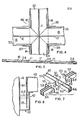
- Fig. 1 illustrates an isometric view of the grid and its supporting structure.
- the support beams 1 are mounted on the ceiling of the room and each one carries a plurality of supporting struts 2 having a turnbuckle 3 to adjust the level of grid 4 to assure retention of the liquid sealant in the individual channel chambers around each of the plurality of filter openings 5.
- the filter supporting members 6 and 7 run lengthwise and crosswise in the room and intersect to form individual channel chambers around each filter opening.
- FIG. 2 illustrates a manner of constructing the intersection of the filter supporting members.
- a main filter supporting member 8 forms a double channel with a liquid sealant retaining channel chamber 9 and liquid sealant retaining channel chamber 10.
- a center dividing wall 11 is connected to a strut 2 placed along the length of the wall to support the main filter supporting member. At intervals along the length of the member 8, a segment is cut away to form openings 12 and 13 to receive cross members 14 and 15. The cross members 14 and 15 extend into the openings 12 and 13 until the center walls 16 and 17 abut the center wall 11 of the main filter supporting member.
- brackets 18 are then positioned on the side walls 19 and 20 of the main filter supporting member 8 and the side walls 21 and 22 of the cross member 14 as well as the side walls 23 and 24 of the cross member 15. This fixes the assembly in its normal operating position and a caulking material " may be used to seal the intersecting walls and bottom surfaces of the filter supporting members to create an independent peripheral channel chamber around the perimeter of each filter opening.
- Fig. 3 is a cross-section view of a filter supporting channel member with the liquid sealant 24 in each of the channel chambers.
- the filter supporting member is cross member 14 shown in Fig. 2 and the center wall 16 is essentially the same height as the two side walls 21, 22.
- Each filter 25 and 26 includes a filtering material 27 and 28.
- a peripheral flange 29 and 30 on each of the two filters extends into the liquid sealant chamber to form a sealed interface 31 and 32 around the portion of the flange extending into the sealant 24.
- the liquid sealant is a heavy viscous material which allows the filter to seat in the operating position and allows the liquid sealant to flow around the flange. Since the liquid sealant is a heavy viscous material, it flows slowly around to form the seal and does not present a problem of splashing due to vibration or any other movement so long as the assembly remains substantially level.
- FIG. 4 the plan view of the assembled components as illustrated and described in Fig. 2 are shown.
- the brackets 18 are in position to retain the cross members 14 and 15 in their assembled position on member 8.
- the center walls 16 and 17 abut the center wall 11 to form a seal at their intersection.
- This forms sealed peripheral channel chambers 31, 32, 33, 34 around each of the filter openings 35, 36, 37 and 38. Since each perimeter channel chamber is isolated from its adjacent channel chamber, the net effect is an isolation of the liquid sealant in adjacent chambers and any filter can be replaced with another filter without interfering with the seal of the adjacent filter.
- Fig. 5 illustrates the effect of the liquid sealant seeking its own level. Although it is preferred to have a level ceiling, minor variations from level may be present or may be caused due to the settling of a building. With the present design, liquid sealant does not run over the walls due to minor variations from level since the length of each channel chamber is limited to the length of the filter it supports. Because of this preferred construction, the danger of leakage due to minor variations from level is eliminated.
- Fig. 6 illustrates a wall supported channel 39 in which the side wall 40 of the channel 39 is supported on the wall 41 of the room.
- the interior wall 42 of the channel provides a support for the filter 43.
- the liquid sealant 44 provides a seal around the peripheral flange 45 extending into the liquid sealant.
- the operation of this channel is the same as that provided in the channel chambers as illustrated in Fig. 4, although only a single channel is necessary since it is mounted on the wall.
- Fig. 7 illustrates a modification of the construction of the grid wherein the main filter support member 50 is formed with openings 50 and 51 to receive cross members 53 and 54.
- Flanges 55 and 56 can be bolted or riveted to the side walls 57 and 58 through the openings 59, 60, 61 and 62 provided, similarly, flanges 63 and 64 can be bolted or riveted to the side walls 65 and 66 through openings 67, 68, 69 and 70.
- the filter device operates in substantially the following manner.
- the support beams 1 are carried on the ceiling of the room and the struts 2 are carried on the support beams which in turn carry the grid 4.
- the position of the grid 4 can be adjusted by the turnbuckles 3 to assure a reasonably level position.
- the intersections are then joined by placing the brackets 18 in their assembled position to retain the main filter support members 8 with the cross filter support members 14 and 15 as shown in Fig: 2 and assembled in Fig.4.
- a caulking material can be used to assure seal integrity at the intersection once the assembly is made.
- the liquid sealant which is a viscous material, is added to each perimeter channel chamber.
- the liquid sealant is heated and poured into the channel chambers 9 and 10, as shown in Fi g .
- the filters then can be seated in position so they rest on the outer walls or the channels as indicated in Fig. 3 and Fig. 6. It is not necessary that the channels be pressed into the liquid sealant since the sealant, although viscous, will allow the filter to settle in position and form an airtight seal around the filter once it is assembled.
- the filter assembly provides an airtight sealing and filtering arrangement to assure clean air operating conditions when the heating or air conditioning ventilating system is in operation.
Abstract
Description
- This invention relates to an air filtering system and more particularly to a sealing grid composed of double channels arranged to form a plurality of filter openings with an independent perimeter channel chamber around each filter opening for receiving a liquid sealant which forms an airtight seal between the peripheral flange of a filter mounted in each opening.
- Clean room facilities, such as areas used for the production of precision instruments or tooling, generally require an even temperature and a dust free environment. Covering the entire ceiling with a plurality of filters allow a gentle flow of filtered air into the room at a reduced air velocity with a decreased filter resistance and power required in the air filtering system. A grid is required to support the filters and a suitable sealing material must be provided at the periphery of the filters to avoid any leakage and assure complete filtering of the air entering the room.
- U.S. patent 3,486,311 provides for a channel grid work in which a flange on the periphery of each filter is allowed to seat in the liquid sealant in the channel and form an air seal between the filter and the grid work. The knife edges of adjacent filters are received in the same channel. In existing systems, the channels extend the length and width of the room and all channels are in continuous liquid communication with each other. The applicant's invention provides for a double channel arrangement in which the flange of each filter is received in a separate channel isolated from the channel receiving the flange of the adjacent filter. This allows removal of any one filter for replacement with another filter as may be required without disturbing the seal of the adjacent filter. It also provides for a shorter channel chamber since the center wall formed by each channel member operates as a divider to isolate each perimeter channel chamber around each filter element. This decreases the need for a precisely level condition of the grid work because each channel chamber is essentially the length and width of the filter and is much shorter than that of U.S. patent 3,486,311 in which the channel chamber is the length and width of the room. Because of the shorter chamber length and width, fewer hangers are needed to support the grid work and greater flexibility of hanger location is permitted to allow for ducts, pipes, etc. The whole grid work need not be the same level and perimeter channel chambers can be leveled individually. Accordingly, these improved features are believed to patentably distinguish the applicant's invention over this patent.
- It is an object of this invention to provide a sealed filter arrangement including a filter supporting grid of channels with liquid sealant retained therein constructed so that an independent perimeter channel chamber is positioned around each filter opening. A filter element having a peripheral flange is received in the perimeter channel chamber around each filter opening to provide a leak proof filter assembly.
- It is another object of this invention to provide a sealed filter bank to provide clean air filtering requirements.
- It is a further object of this invention to provide a filter supporting grid having channels defining filter openings and a perimeter channel chamber retaining liquid sealant around each filter opening adapted to receive a peripheral flange of each filter element to form a leak proof filter assembly.
- The objects of this invention are accomplished by a grid formed by filter support members with main members running parallel the length of the ceiling and cross members running between the main members, both formed of a double channel construction and with liquid sealant received in each perimeter channel chamber around each filter opening. The filter openings are covered by a filter element having a downwardly extending peripheral flange extending into the liquid sealant-in the channel chamber to form a sealed filter assembly. Each perimeter channel chamber is essentially the size of the filter.
- Referring to the drawings, the preferred embodiment of this invention is illustrated.
- Fig. 1 is an isometric view of the grid supported from the ceiling with leveling adjustments on the supporting structure;
- Fig. 2 is an exploded view of the channel intersection at the corner of each filter opening;
- Fig. 3 is a cross-section view taken through a filter supporting channel cross member in the assembled position with the filters in the operating position;
- Fig. 4 is the plan view of the assembled intersection of the filter supporting member;
- Fig. 5 is a side elevation view showing the isolated chambers around each of the filter openings;
- Fig. 6 is a cross-section view taken through a wall supported channel with the filter in the operating position; and
- Fig. 7 is an exploded view of a modification of the channel intersection.
- Referring to the drawings, Fig. 1 illustrates an isometric view of the grid and its supporting structure. The support beams 1 are mounted on the ceiling of the room and each one carries a plurality of supporting struts 2 having a
turnbuckle 3 to adjust the level ofgrid 4 to assure retention of the liquid sealant in the individual channel chambers around each of the plurality offilter openings 5. The filter supporting members 6 and 7 run lengthwise and crosswise in the room and intersect to form individual channel chambers around each filter opening. - Fig. 2 illustrates a manner of constructing the intersection of the filter supporting members. A main
filter supporting member 8 forms a double channel with a liquid sealant retaining channel chamber 9 and liquid sealantretaining channel chamber 10. Acenter dividing wall 11 is connected to a strut 2 placed along the length of the wall to support the main filter supporting member. At intervals along the length of themember 8, a segment is cut away to formopenings cross members cross members openings center walls center wall 11 of the main filter supporting member. When the cross members are inserted in position, thebrackets 18 are then positioned on theside walls 19 and 20 of the mainfilter supporting member 8 and theside walls cross member 14 as well as theside walls cross member 15. This fixes the assembly in its normal operating position and a caulking material " may be used to seal the intersecting walls and bottom surfaces of the filter supporting members to create an independent peripheral channel chamber around the perimeter of each filter opening. - Fig. 3 is a cross-section view of a filter supporting channel member with the
liquid sealant 24 in each of the channel chambers. For the purpose of illustration, it will be assumed that the filter supporting member iscross member 14 shown in Fig. 2 and thecenter wall 16 is essentially the same height as the twoside walls filter filtering material peripheral flange interface sealant 24. The liquid sealant is a heavy viscous material which allows the filter to seat in the operating position and allows the liquid sealant to flow around the flange. Since the liquid sealant is a heavy viscous material, it flows slowly around to form the seal and does not present a problem of splashing due to vibration or any other movement so long as the assembly remains substantially level. - Referring to Fig. 4, the plan view of the assembled components as illustrated and described in Fig. 2 are shown. The
brackets 18 are in position to retain thecross members member 8. Thecenter walls center wall 11 to form a seal at their intersection. This forms sealedperipheral channel chambers filter openings - Fig. 5 illustrates the effect of the liquid sealant seeking its own level. Although it is preferred to have a level ceiling, minor variations from level may be present or may be caused due to the settling of a building. With the present design, liquid sealant does not run over the walls due to minor variations from level since the length of each channel chamber is limited to the length of the filter it supports. Because of this preferred construction, the danger of leakage due to minor variations from level is eliminated.
- Fig. 6 illustrates a wall supported
channel 39 in which theside wall 40 of thechannel 39 is supported on thewall 41 of the room. Theinterior wall 42 of the channel provides a support for thefilter 43. Theliquid sealant 44 provides a seal around theperipheral flange 45 extending into the liquid sealant. The operation of this channel is the same as that provided in the channel chambers as illustrated in Fig. 4, although only a single channel is necessary since it is mounted on the wall. - Fig. 7 illustrates a modification of the construction of the grid wherein the main
filter support member 50 is formed withopenings cross members Flanges side walls 57 and 58 through theopenings flanges side walls openings - The filter device operates in substantially the following manner. The support beams 1 are carried on the ceiling of the room and the struts 2 are carried on the support beams which in turn carry the
grid 4. The position of thegrid 4 can be adjusted by theturnbuckles 3 to assure a reasonably level position. The intersections are then joined by placing thebrackets 18 in their assembled position to retain the mainfilter support members 8 with the crossfilter support members channel chambers 9 and 10, as shown in Fig. 3, until it reaches a level in the chamber sufficient to cover the lower ends of theflanges
Claims (8)
characterized by;
Priority Applications (1)
| Application Number | Priority Date | Filing Date | Title |
|---|---|---|---|
| AT84116155T ATE47330T1 (en) | 1983-12-22 | 1984-12-21 | AIR CLEANER SYSTEM WITH SUPPORT AND SEALING GRID. |
Applications Claiming Priority (2)
| Application Number | Priority Date | Filing Date | Title |
|---|---|---|---|
| US564570 | 1983-12-22 | ||
| US06/564,570 US4545793A (en) | 1983-12-22 | 1983-12-22 | Air filter system with supporting and sealing grid |
Publications (3)
| Publication Number | Publication Date |
|---|---|
| EP0146958A2 true EP0146958A2 (en) | 1985-07-03 |
| EP0146958A3 EP0146958A3 (en) | 1986-12-03 |
| EP0146958B1 EP0146958B1 (en) | 1989-10-18 |
Family
ID=24255003
Family Applications (1)
| Application Number | Title | Priority Date | Filing Date |
|---|---|---|---|
| EP84116155A Expired EP0146958B1 (en) | 1983-12-22 | 1984-12-21 | Air filter system with supporting and sealing grid |
Country Status (11)
| Country | Link |
|---|---|
| US (1) | US4545793A (en) |
| EP (1) | EP0146958B1 (en) |
| JP (1) | JPS60147215A (en) |
| AT (1) | ATE47330T1 (en) |
| CA (1) | CA1265454A (en) |
| DE (1) | DE3480176D1 (en) |
| DK (1) | DK599784A (en) |
| ES (1) | ES292682Y (en) |
| FI (1) | FI85821C (en) |
| IL (1) | IL73887A (en) |
| NO (1) | NO161605C (en) |
Cited By (2)
| Publication number | Priority date | Publication date | Assignee | Title |
|---|---|---|---|---|
| EP0262515A3 (en) * | 1986-10-03 | 1989-09-20 | Kessler & Luch Gmbh | Screen for filter frame |
| US4963495A (en) * | 1984-10-05 | 1990-10-16 | Genentech, Inc. | Secretion of heterologous proteins |
Families Citing this family (13)
| Publication number | Priority date | Publication date | Assignee | Title |
|---|---|---|---|---|
| DE3447901C2 (en) * | 1984-12-28 | 1994-07-07 | Flaekt Ab | Modular frame arrangement that can be suspended from the ceiling of a room to hold filters with a fluid seal for clean room ceilings |
| SE456260B (en) * | 1985-01-29 | 1988-09-19 | Flaekt Ab | ROOF ROOFING RECTANGULAR FILTER ELEMENT |
| US4678487A (en) * | 1985-05-14 | 1987-07-07 | Flanders Filters, Inc. | Laminar flow clean room having improved filter bank |
| US4769958A (en) * | 1985-12-03 | 1988-09-13 | Limp Edgar W | Clean-room suspended ceiling |
| JPS62136221A (en) * | 1985-12-10 | 1987-06-19 | Nitta Kk | Air filter apparatus |
| US4860420A (en) * | 1987-04-07 | 1989-08-29 | Flanders Filters, Inc. | Method of fabricating a clean room filter bank |
| US4883511A (en) * | 1988-03-25 | 1989-11-28 | Arnold Gustin | Laminar flow multiplane matrix ceiling system |
| US4986050A (en) * | 1989-08-22 | 1991-01-22 | Filtra Corporation | Modular support system for a filter-type ceiling grid |
| US5540028A (en) * | 1994-07-05 | 1996-07-30 | Scott; Robert D. | HEPA filter ceiling assembly with in-situ gelation of sealant |
| US5871556A (en) * | 1997-05-02 | 1999-02-16 | Hepa Corporation | Clean room air filter system with self-supporting filter units |
| US6797028B2 (en) | 2002-02-13 | 2004-09-28 | 3M Innovative Properties Company | “Push-on” self attach adaptive filter |
| US7146770B2 (en) * | 2002-11-05 | 2006-12-12 | Simmons Robert J | Angle-section column-beam connector |
| JP4660392B2 (en) * | 2006-02-13 | 2011-03-30 | ニッタ株式会社 | Air filter and air filter manufacturing method |
Citations (2)
| Publication number | Priority date | Publication date | Assignee | Title |
|---|---|---|---|---|
| US3486311A (en) * | 1967-12-22 | 1969-12-30 | Flanders Filters | Filter bank assembly |
| US4233044A (en) * | 1976-05-13 | 1980-11-11 | Flanders Filters, Inc. | Self-cleaning fluid sealed air filter |
Family Cites Families (5)
| Publication number | Priority date | Publication date | Assignee | Title |
|---|---|---|---|---|
| US1189492A (en) * | 1913-11-18 | 1916-07-04 | Joseph Schanman | Rail building. |
| US3485519A (en) * | 1967-07-24 | 1969-12-23 | Joseph Chak Fai Chiu | Readily demountable constructional unit |
| US3716259A (en) * | 1970-11-23 | 1973-02-13 | Skydyne Inc | Bonded construction |
| US4088463A (en) * | 1976-05-05 | 1978-05-09 | Frederick L. Fichter | Filtration module |
| US4047348A (en) * | 1976-06-28 | 1977-09-13 | Johns-Manville Corporation | Ceiling support grid system |
-
1983
- 1983-12-22 US US06/564,570 patent/US4545793A/en not_active Expired - Fee Related
-
1984
- 1984-11-28 CA CA000468836A patent/CA1265454A/en not_active Expired - Lifetime
- 1984-12-03 FI FI844754A patent/FI85821C/en not_active IP Right Cessation
- 1984-12-12 ES ES1984292682U patent/ES292682Y/en not_active Expired
- 1984-12-13 JP JP59263711A patent/JPS60147215A/en active Pending
- 1984-12-14 DK DK599784A patent/DK599784A/en not_active Application Discontinuation
- 1984-12-20 NO NO845121A patent/NO161605C/en unknown
- 1984-12-20 IL IL73887A patent/IL73887A/en unknown
- 1984-12-21 AT AT84116155T patent/ATE47330T1/en not_active IP Right Cessation
- 1984-12-21 DE DE8484116155T patent/DE3480176D1/en not_active Expired
- 1984-12-21 EP EP84116155A patent/EP0146958B1/en not_active Expired
Patent Citations (2)
| Publication number | Priority date | Publication date | Assignee | Title |
|---|---|---|---|---|
| US3486311A (en) * | 1967-12-22 | 1969-12-30 | Flanders Filters | Filter bank assembly |
| US4233044A (en) * | 1976-05-13 | 1980-11-11 | Flanders Filters, Inc. | Self-cleaning fluid sealed air filter |
Cited By (2)
| Publication number | Priority date | Publication date | Assignee | Title |
|---|---|---|---|---|
| US4963495A (en) * | 1984-10-05 | 1990-10-16 | Genentech, Inc. | Secretion of heterologous proteins |
| EP0262515A3 (en) * | 1986-10-03 | 1989-09-20 | Kessler & Luch Gmbh | Screen for filter frame |
Also Published As
| Publication number | Publication date |
|---|---|
| ES292682Y (en) | 1987-04-16 |
| EP0146958A3 (en) | 1986-12-03 |
| EP0146958B1 (en) | 1989-10-18 |
| CA1265454C (en) | 1990-02-06 |
| CA1265454A (en) | 1990-02-06 |
| FI85821C (en) | 1992-06-10 |
| DE3480176D1 (en) | 1989-11-23 |
| IL73887A0 (en) | 1985-03-31 |
| DK599784D0 (en) | 1984-12-14 |
| NO161605B (en) | 1989-05-29 |
| ATE47330T1 (en) | 1989-11-15 |
| JPS60147215A (en) | 1985-08-03 |
| FI844754L (en) | 1985-06-23 |
| ES292682U (en) | 1986-08-01 |
| NO845121L (en) | 1985-06-24 |
| IL73887A (en) | 1988-11-15 |
| FI844754A0 (en) | 1984-12-03 |
| DK599784A (en) | 1985-06-23 |
| US4545793A (en) | 1985-10-08 |
| FI85821B (en) | 1992-02-28 |
| NO161605C (en) | 1989-09-06 |
Similar Documents
| Publication | Publication Date | Title |
|---|---|---|
| US4555255A (en) | Corner connector clip in an air filter grid | |
| EP0146958B1 (en) | Air filter system with supporting and sealing grid | |
| US4511380A (en) | Suspension and sealing of latticework and filters | |
| US3486311A (en) | Filter bank assembly | |
| US4699640A (en) | Clean room having partially different degree of cleanliness | |
| CA1266200A (en) | Air filtering and distribution for laminar flow clean room | |
| EP0180139A2 (en) | Clean room | |
| US3782082A (en) | Ceiling filter system for clean room | |
| US20020134061A1 (en) | Modular clean room filter system | |
| US4600419A (en) | High efficiency, down flow air filter sealing and support system | |
| US5865674A (en) | Flush lighting system for cleanroom | |
| CA2110694A1 (en) | Clean-room ceiling module | |
| US3788206A (en) | Modular ceiling construction | |
| US4747341A (en) | Integral grid structure for providing negative pressure plenum | |
| US2716490A (en) | Filter construction | |
| AU2001229259B2 (en) | Modular clean room filter system | |
| AU2001229259A1 (en) | Modular clean room filter system | |
| US3590719A (en) | Polygonal tile, suspended ceiling integrated acoustiplaque air diffuser assembly | |
| US3470658A (en) | Prefabricated extendable enclosure | |
| JPH0515927Y2 (en) | ||
| SU1311760A1 (en) | Cell for pocket-type filter | |
| JP2515245B2 (en) | Flexible clean room | |
| FI72176B (en) | I EN VENTILATIONSOEPPNING MONTERBART FILTERELEMENT | |
| RU2008426C1 (en) | Partition wall | |
| SU1040078A1 (en) | Network shell |
Legal Events
| Date | Code | Title | Description |
|---|---|---|---|
| PUAI | Public reference made under article 153(3) epc to a published international application that has entered the european phase |
Free format text: ORIGINAL CODE: 0009012 |
|
| AK | Designated contracting states |
Designated state(s): AT BE CH DE FR GB IT LI LU NL SE |
|
| PUAL | Search report despatched |
Free format text: ORIGINAL CODE: 0009013 |
|
| AK | Designated contracting states |
Kind code of ref document: A3 Designated state(s): AT BE CH DE FR GB IT LI LU NL SE |
|
| 17P | Request for examination filed |
Effective date: 19870410 |
|
| 17Q | First examination report despatched |
Effective date: 19871027 |
|
| GRAA | (expected) grant |
Free format text: ORIGINAL CODE: 0009210 |
|
| RAP1 | Party data changed (applicant data changed or rights of an application transferred) |
Owner name: SNYDERGENERAL CORPORATION |
|
| AK | Designated contracting states |
Kind code of ref document: B1 Designated state(s): AT BE CH DE FR GB IT LI LU NL SE |
|
| ITF | It: translation for a ep patent filed |
Owner name: BARZANO' E ZANARDO MILANO S.P.A. |
|
| REF | Corresponds to: |
Ref document number: 47330 Country of ref document: AT Date of ref document: 19891115 Kind code of ref document: T |
|
| REF | Corresponds to: |
Ref document number: 3480176 Country of ref document: DE Date of ref document: 19891123 |
|
| ET | Fr: translation filed | ||
| PLBE | No opposition filed within time limit |
Free format text: ORIGINAL CODE: 0009261 |
|
| STAA | Information on the status of an ep patent application or granted ep patent |
Free format text: STATUS: NO OPPOSITION FILED WITHIN TIME LIMIT |
|
| 26N | No opposition filed | ||
| ITTA | It: last paid annual fee | ||
| PGFP | Annual fee paid to national office [announced via postgrant information from national office to epo] |
Ref country code: AT Payment date: 19921019 Year of fee payment: 9 |
|
| PGFP | Annual fee paid to national office [announced via postgrant information from national office to epo] |
Ref country code: SE Payment date: 19921214 Year of fee payment: 9 Ref country code: GB Payment date: 19921214 Year of fee payment: 9 |
|
| PGFP | Annual fee paid to national office [announced via postgrant information from national office to epo] |
Ref country code: FR Payment date: 19921216 Year of fee payment: 9 |
|
| PGFP | Annual fee paid to national office [announced via postgrant information from national office to epo] |
Ref country code: CH Payment date: 19921223 Year of fee payment: 9 |
|
| PGFP | Annual fee paid to national office [announced via postgrant information from national office to epo] |
Ref country code: NL Payment date: 19921231 Year of fee payment: 9 |
|
| PGFP | Annual fee paid to national office [announced via postgrant information from national office to epo] |
Ref country code: LU Payment date: 19930105 Year of fee payment: 9 |
|
| PGFP | Annual fee paid to national office [announced via postgrant information from national office to epo] |
Ref country code: DE Payment date: 19930115 Year of fee payment: 9 |
|
| PGFP | Annual fee paid to national office [announced via postgrant information from national office to epo] |
Ref country code: BE Payment date: 19930127 Year of fee payment: 9 |
|
| EPTA | Lu: last paid annual fee | ||
| PG25 | Lapsed in a contracting state [announced via postgrant information from national office to epo] |
Ref country code: LU Free format text: LAPSE BECAUSE OF NON-PAYMENT OF DUE FEES Effective date: 19931221 Ref country code: GB Effective date: 19931221 Ref country code: AT Effective date: 19931221 |
|
| PG25 | Lapsed in a contracting state [announced via postgrant information from national office to epo] |
Ref country code: SE Effective date: 19931222 |
|
| PG25 | Lapsed in a contracting state [announced via postgrant information from national office to epo] |
Ref country code: LI Effective date: 19931231 Ref country code: CH Effective date: 19931231 Ref country code: BE Effective date: 19931231 |
|
| BERE | Be: lapsed |
Owner name: SNYDERGENERAL CORP. Effective date: 19931231 |
|
| PG25 | Lapsed in a contracting state [announced via postgrant information from national office to epo] |
Ref country code: NL Effective date: 19940701 |
|
| NLV4 | Nl: lapsed or anulled due to non-payment of the annual fee | ||
| GBPC | Gb: european patent ceased through non-payment of renewal fee |
Effective date: 19931221 |
|
| PG25 | Lapsed in a contracting state [announced via postgrant information from national office to epo] |
Ref country code: FR Effective date: 19940831 |
|
| REG | Reference to a national code |
Ref country code: CH Ref legal event code: PL |
|
| PG25 | Lapsed in a contracting state [announced via postgrant information from national office to epo] |
Ref country code: DE Effective date: 19940901 |
|
| REG | Reference to a national code |
Ref country code: CH Ref legal event code: AUV Free format text: LE BREVET CI-DESSUS EST TOMBE EN DECHEANCE, FAUTE DE PAIEMENT, DE LA 10E ANNUITE. |
|
| REG | Reference to a national code |
Ref country code: FR Ref legal event code: ST |
|
| EUG | Se: european patent has lapsed |
Ref document number: 84116155.7 Effective date: 19940710 |