EP0160472A2 - Reprogrammable call forwarding device - Google Patents
Reprogrammable call forwarding device Download PDFInfo
- Publication number
- EP0160472A2 EP0160472A2 EP19850302782 EP85302782A EP0160472A2 EP 0160472 A2 EP0160472 A2 EP 0160472A2 EP 19850302782 EP19850302782 EP 19850302782 EP 85302782 A EP85302782 A EP 85302782A EP 0160472 A2 EP0160472 A2 EP 0160472A2
- Authority
- EP
- European Patent Office
- Prior art keywords
- phone
- forwarding
- signal
- message
- stored
- Prior art date
- Legal status (The legal status is an assumption and is not a legal conclusion. Google has not performed a legal analysis and makes no representation as to the accuracy of the status listed.)
- Granted
Links
Images
Classifications
-
- H—ELECTRICITY
- H04—ELECTRIC COMMUNICATION TECHNIQUE
- H04M—TELEPHONIC COMMUNICATION
- H04M1/00—Substation equipment, e.g. for use by subscribers
- H04M1/006—Call diverting means
Definitions
- This invention relates to telephone systems and more particularly to an automatic call forwarding device that provides call forwarding from any selected forwarding phone having three-way conference service provided by a central exchange telephone equipment having an electronic switching system.
- Engel U. S. Patent No. 2,124,913 discloses a relay at the telephone exchange and a calling relay at the forwarding station that is energized by the caller so that, when a call is made by the calling station, the device at the forwarding station instructs the exchange to dial a different number.
- U. S. Patent No. 3,510,598 discloses a telephone call diverter and answering device which answers a call with a greeting prerecorded on a storage drum.
- the new telephone number is also stored on the storage drum, and means are provided whereby a number is automatically dialed to connect the caller to the new number and for remotely changing the transfer number.
- Sousa U. S. Patent No. 3,959,600 discloses means for reprogramming the transfer number in a two- telephone line system.
- an automatic reprogrammable call forwarding device for a forwarding phone that is coupled by a single forwarding phone line to central exchange telephone equipment having an electronic switching system and providing three-way conference service to said forwarding phone, said device comprising:
- An automatic call forwarding device is connected to a forwarding phone having a three-way conference service and which is connected by a single phone line to central exchange telephone equipment having an electronic switching system and a three-way conference service.
- the device operates to cause the calling phone to be put on hold while a message transmitting and storage device transmits dialing pulses of another phone representing the number of that phone which the telephone company will recognize and the telephone equipment will operate to connect the calling phone to that third phone.
- the device is adapted to be reprogrammed by encoder signals provided by the tone pulses of a standard touch tone telephone or a hand encoder with identical tone pulses.
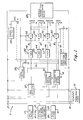
- FIG. 1 a call forwarding device generally designated by numeral 11 embodying features of the present invention.
- Central exchange telephone equipment 12 is shown connected by a single phone line comprising two wires, designated by numerals 13 and 14, to a forwarding phone 15.
- Device 11 is connected across the forwarding phone line 13 and 14 so as to operate in parallel therewith.
- FIG. 1 a calling phone 17 coupled to the telephone equipment 12 by lines 18 and 19 and a third phone 21 coupled to the telephone equipment by lines 22 and 23.
- the central telephone equipment 12 has an electronic switching system and provides three-way conference service to the forwarding phone.
- This equipment has the capability of forwarding a call from a calling phone to a third phone when a certain sequence of operation is performed. This sequence involves moving the forwarding phone to an off-hook condition and the depressing of the switch hook of the forwarding phone for a certain time interval, after which the telephone equipment places the calling phone on hold. The number of a third phone to which the call is to be forwarded is then dialed at the forwarding phone and the switch hook of the forwarding phone is depressed a second time for a certain time interval, whereupon the telephone equipment will connect the calling phone to the third phone to complete the call forwarding operation.
- Device 11 shown includes a message transmitting and storing device 25 connected across the forwarding phone line.
- Device 25 shown is a mechanical device such as a conventional phone answering device.
- Device 25 has a tape which serves as a storage medium on which tone signal messages may be stored.
- Device 25 has a transmit mode of operation that is effected when actuating a start button, after which stored messages are read out from the tape over the phone line and back to the telephone equipment.
- Device 25 has a store mode of operation that is effected by actuating a record button, during which incoming tone signal messages over the phone line are stored on the tape.
- Device 25 further has a reset mode of operation that is effected by actuating a stop button and a rewind button, after which the storage means is reset for either storing a message or transmitting a stored message.
- the storage device 25 may be reprogrammed and/or reset from any third phone in the telephone system having the tone pulses of a standard touch tone telephone or a hand encoder with identical tone pulses.
- the storage device can be, for example, a conventional telephone answering device, a tape recorder, or a solid state memory chip.
- a start solenoid Ll, rewind solenoid L2, record solenoid L3, and stop solenoid L4 are shown adjacent device 25 which upon energization serve to effect the actuation of the above described corresponding buttons on device 25.
- Device 11 includes a ring detector 27 connected across the forwarding phone line which, in response to an incoming call from equipment 12, provides an output signal indicating that a call is being received from the equipment to the forwarding phone.
- Device 11 further includes a hook condition simulator 29 connected across the forwarding phone line with a solenoid Kl that is selectively energized to change the state of the output therefrom.
- Simulator 29 is basically an impedance device that has one state at the output representing an off-hook condition at the forwarding phone and a second state representing a hook switch flash condition, which is essentially a short circuit.
- Device 11 has a transmitted signal sensor 31 connected across the forwarding phone line which, for example, may be a hash W)tone detector that will detect a selected tone at the end of the telephone number that has been transmitted from device 25.
- Device 11 has an incoming signal sensor 33 associated with the reprogramming mode of operation and responsive to a reprogrammable message signal generated at the calling phone or locally.
- sensor 33 is a tone detector which will detect the * (star) tone signal.
- the incoming signal includes a reprogram tone signal, a new telephone number to which the call is to be forwarded, and a reset tone signal whereupon, when the calling phone transmits the signal, a new number is stored in device 25 and the device is then reset for the next call or a new number.
- the ring detector 27 is shown as having its output connected to a timer 42 and the timer by line 51 to an electronic circuit El.
- the output of El is connected to start solenoid Ll and simulator solenoid Kl.
- the output of the ring detector 27 is shown connected directly to solenoid K1 by line 85.
- the transmitted signal tone sensor 31 has an output connected to coil Kl by line 85.
- the transmitted signal tone sensor 31 has an output connected through a timer 44 which in turn connects to an electronic circuit E2 via line 61, in turn connecting to rewind solenoid L2.
- the sensor 31 is a tone detector that will detect the (hash) tone signal.
- the incoming signal sensor 33 is connected to a timer 46 which is connected to a third electronic circuit E3 via line 71 which controls the record solenoid L3.
- the output from sensor 31 connects to a fourth electronic circuit E4 which controls stop solenoid L4.
- This voice control circuit which is also connected across the forwarding phone line.
- This voice control circuit 35 is optional and in general operates to turn off the device 11 after there has been no voice on the line for a predetermined time interval.
- the voice control circuit controls a relay coil K2 which closes a normally open contact K2A upon energization.
- a power supply 38 is shown as having an output designated + that biases the electronic circuits El, E2, E3 and E4 via their associated timers as well as sensors 31 and 33.
- the power terminal + of the power supply 38 also applies a bias voltage to several of the circuits shown through contact K2A, as is described more fully hereinafter.
- contact K2A In response to the first ring, then, contact K2A is closed. Contact K2A controls electric power from the power supply 38 to bias the voice control circuit 35 and electronic circuits El, E2, E3 and E4.
- the ring detector 27 responds to the ring and initially energizes solenoid K1 to cause simulator 29 to simulate an off-hook condition indicating to the equipment that the phone has been answered.
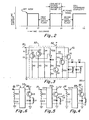
- This off-hook condition is a current flow of a certain magnitude in the power line 13, 14 and is represented on the graph of Figure 2, beginning at time tl.
- the output of ring detector 27 causes timer 42 to turn on for a preselected time interval such as approximately one second between tl ard t2.
- the timer 42 connects the voltage of the power supply 38 to a first electronic circuit El, which causes the charging capacitor Cl described hereinafter to charge in readiness for use.
- a de-energization for a time interval between t2 and t3 of about one second which simulates a first hook switch flash, during which the equipment 12 places the calling phone on hold and the central equipment produces a dial tone to the forwarding phone.
- the power supply voltage is removed from the first electronic circuit El. Because of a charge on the capacitor Cl and operation of the first electronic circuit El, the capacitor Cl is discharged, resulting in energization of the coil of solenoid Ll and the coil of relay Kl for a time interval of about one second.
- Energization of the solenoid Ll actuates the start storing operation of the device 25 to start same.
- the time interval between t3 and t4 there is sufficient time to obtain the dial tone from equipment 12 and allow device 25 to transmit dialing pulses of a selected third phone number that have been recorded on the storage medium of device 25 and are received by the central office telephone equipment 12.
- the occurrence of the pound pulse # is at the end of the transmission of the dialing pulses by device 25, designated t4.
- a transmitted signal pulse such as the hash pulse (#) triggers the sensor 31 to again actuate relay Kl for the second time for the required time interval in a second hook switch flash operation between intervals t4 and t5, thereby providing the sequence on the phone line that will cause the telephone equipment 12 to connect the calling phone to the selected third phone so that the call forwarding is now completed.
- the time intervals tl through t5 are only approximate representations, with t3 to t4 typically being longer than tl to t2.
- the closure of contact K2A by the voice control circuit applies a charging voltage to a charging capacitor C2 in the second electronic circuit E2 so that it is in readiness for use.
- the transmit signal sensor 31 is connected to a timer 44 which in turn controls the activation of a rewind solenoid L2 via line 61.
- a transmitted signal pulse such as the hash pulse triggers the detector 31 to interrupt the power from the power supply to the circuit E2 so that this circuit is interrupted or turned off.
- the voice control circuit 35 is activated to actuate rewind solenoid L2 and relay K2A is energized and remains energized in response to a voice on the line, so contact K2A is closed. After the voice is removed for a time period of about eight seconds, coil K2 is de-energized and contact K2A opens, the power is removed from electronic circuits El through E4 and the voice control circuit, and the device is reset for the next call.
- a calling phone has a reprogramming operator that first inputs a particular program signal, which in the present example is the * (star) tone signal, that operates record solenoid L3.
- the new telephone number is dialed by the calling phone and this is recorded by device 25.
- a transmitted signal tone such as, for example, the # (hash) tone is added by the reprogramming operator to operate the solenoid L4 to stop device 25.
- a third electronic circuit E3 receives power from the power supply 38 via a timer 46.
- Circuit E3 has a charging capacitor C3.
- the incoming signal tone sensor 33 connects to timer 46, which in turn connects via line 71 to circuit E3 and circuit E3 to record solenoid L3.
- circuit E3 operates and solenoid L3 is energized for approximately one second to press the record button and simultaneously solenoid Ll is activated to press the start button. This puts the recorder into record readiness. At this time the desired onward call forwarding pulses are recorded.
- the calling or reprogramming phone has to produce the tone pulses of a standard touch tone telephone or a hand encoder with identical tone pulses.
- a transmitted signal i.e., # (hash) pulse is added by the operator which is reprogramming to stop the recorder by a fourth electronic circuit.
- Electronic circuit E4 receives an output from sensor 31, which activates solenoid L4 to stop the recorder. Solenoid L2 is also energized to rewind the record.
- the device 11 is now reprogrammed for forwarding the new number. Every time a new number is programmed the previous one is automatically erased, as is the case when using a conventional phone answering device using a tape for recording messages.
- the first electronic circuit El is shown in more detail to include the input line 51 from the timer 42 with a resistor Rl and capacitor Cl connected in series between input line 51 and ground.
- Transistors Ql and Q2 are connected in a Darlington configuration with resistor Rl connected between the emitter of transistor Ql and input line 51 and resistor R4 connected between the base of transistor Q2 and line 51.
- a resistor R2 is connected between the collector of transistor Ql and ground and a resistor R3 is connected between the collector of transistor Q2 and ground.
- a resistor R30 is connected between line 51 and a common connection of the collector of Q2 and base of Ql.
- a second stage of the circuit includes transistors Q3, Q4 and Q5 connected to amplify the power produced by the capacitor to energize start solenoids Ll and simulator coil Kl.
- Resistors R6 and R7 connect to the base of transistor Q3 and are connected to the collector of transistor Ql.
- the emitter of transistor Q3 is connected to ground.
- Resistors R9 and R10 are connected between a power terminal 52 and the collector of transistor Q3.
- the base of transistor Q4 connects between resistors R9 and R10.
- a resistor R8 connects between power terminal 52 and the emitter of transistor Q4.
- a resistor R50 connects between the collector of transistor Q5 and ground.
- the emitter of transistor Q5 connects to power terminal 52 and the solenoid Ll is connected between the collector of transistor Q5 and ground.
- a diode D3 is connected across start solenoid L l.
- Another diode D4 is connected between a power terminal 54 and both the collector of transistor Q1 and one side of resistor R6.
- Another series circuit connected between the collector of transistor Q5 and ground includes a diode D1 and coil Kl with a diode D5 connected across coil Kl.
- circuitry including transistors Ql, Q2, Q3 and Q4 and associated resistors is enclosed in a block designated by numeral 53. This circuitry is common to electronic circuits E2, E3 andE4 described hereinafter.
- timer 42 turns on for about one second.
- Timer 42 connects the voltage from the power supply 38 indicated at terminal 55 via line 51 to resistors Rl, R4 and R30.
- Capacitor Cl now charges in readiness for use.
- the bias voltage applied through timer 42 to line 51 is removed.
- transistors Ql and Q2 Because of the charge on capacitor Cl at the emitters of transistors Ql and Q2 and the zero voltage level at the base of transistor Q2, the Darlington configuration of transistors Ql and Q 2 turns on and discharges capacitor Cl across resistors R2, R6 and R7, causing transistor Q3 to turn on for approximately one second.
- the turning on of transistor Q3 causes transistors Q4 and Q5 to turn on, resulting in the energization of start solenoid Ll and simulator coil Kl via diode Dl. Diode D5 across Kl prevents reverse emf spikes from affecting Q5.
- electronic circuit E2 is shown to have an input line 61 from timer 44 with a resistor Rll and charging capacitor C2 connected between line 61 and ground.
- the same electronic circuitry 53 above described is connected between lines 61, resistor Rll, capacitor C2, power terminal 62, transistor Q9 and rewind solenoid L2 such that, when capacitor C2 is discharged, solenoid L2 will be energized.
- a line 95 is shown connected between the output circuits El and E2 through diode D2 so that rewind solenoid L2 and coil Kl are activated simultaneously.
- a third electronic circuit E3 shown in Figure 5 has an input line 71 from the associated timer 46 which applies a voltage across a resistor R22 and charging capacitor C3 and, through circuit 53, connects the power from a discharge capacitor C3 to actuate record solenoid L3 by power from terminal 72 via the collector of transistor Q14.
- the collector of Q14 simultaneously activates start solenoid Ll via diode D4.
- a diode D8 is shown connected across solenoid L3 to prevent back emf spikes from affecting Q14.
- the fourth electronic circuit E4 has an input line 81 directly from sensor 31 connected between resistor R24 and charging capacitor C4 and ground with circuit 53 converting the discharge from capacitor C4 to a signal that will actuate stop solenoid L4.
- a power terminal for circuit 53 is indicated at 82.
- a diode D10 is connected across solenoid L4 to prevent back emf spikes from affecting Q15.
- the above described embodiment utilizes a mechanical device as the message transmitting and storage device 25. It is understood that an equivalent solid state memory chip could be substituted to provide the same functions. In the electronic device 25 the stop function would not be necessary and the rewind is equivalent to a reset function.
- the memory chip for device 25 would have the conventional central processing unit with associated memory and timing controls as well as an input-output control for regulating control signals to and from the central processing unit.
- a ring detector would connect signals from the phone line to the input-output control, a hook condition device would receive signals from the input-output control and pass them to the phone line, and an input signal detector would be connected to the input-output control and its signals would be routed to the phone line through an input-output switch.
- All signals to and from the phone line would be passed through a communication interface that would convert communication level signals into digital level signals for communication with the computer chip.
Abstract
Description
- This invention relates to telephone systems and more particularly to an automatic call forwarding device that provides call forwarding from any selected forwarding phone having three-way conference service provided by a central exchange telephone equipment having an electronic switching system.
- Persons that are traveling from location to location during a workday have difficulty in being reached. There has been widespread use of phone answering devices but the drawback of these is that some people do not want to leave messages. Attempts have been made to provide call forwarding whereby a person out in the field with access to a phone may have his calls forwarded directly to his present location, which in operation does not require a person present at the forwarding phone. It is preferred to have this call forwarding accomplished in a relatively simple manner without the caller knowing that the transfer has been made.
- Prior known call forwarding technology with remote programming change capability has required the use of a switch box at the forwarding phone and two telephone lines from the phone company to the switch box.
- Engel U. S. Patent No. 2,124,913 discloses a relay at the telephone exchange and a calling relay at the forwarding station that is energized by the caller so that, when a call is made by the calling station, the device at the forwarding station instructs the exchange to dial a different number.
- Ballin et al. U. S. Patent No. 3,510,598 discloses a telephone call diverter and answering device which answers a call with a greeting prerecorded on a storage drum. The new telephone number is also stored on the storage drum, and means are provided whereby a number is automatically dialed to connect the caller to the new number and for remotely changing the transfer number.
- Sousa U. S. Patent No. 3,959,600 discloses means for reprogramming the transfer number in a two- telephone line system.
- Recently available services by some telephone companies provide call forwarding on a single line, but there are no known call forwarding devices presently available, using a single line, that are reprogrammable either remotely or locally.
- According to the invention, there is provided an automatic reprogrammable call forwarding device for a forwarding phone that is coupled by a single forwarding phone line to central exchange telephone equipment having an electronic switching system and providing three-way conference service to said forwarding phone, said device comprising:
- message transmitting and storage means operatively associated with a forwarding phone line,
- said message transmitting and storage means including a storage medium on which tone signal messages may be stored,
- said message transmitting and storage means having a transmit mode of operation during which stored messages are read out from said storage medium, a store mode of operation during which incoming tone signal messages are stored in said storage medium, and a reset mode during which said storage means is reset for either storing a message or transmitting a stored message;
- ring detector means operatively associated with said forwarding phone line providing an output signal indicating a phone call signal is being received from said equipment over said forwarding phone line;
- hook condition simulator means operatively associated with said forwarding phone line having a state simulating the forwarding phone line output signal representing an off-hook condition and a state simulating a hook switch flash condition;
- first sensing means operatively associated with said forwarding phone line providing an indication that said stored message has been transmitted,
- whereby, when the calling phone calls the forwarding phone, in succession said ring detector produces an output that causes said simulating means to simulate an off-hook condition indicating to said equipment that said forwarding phone has been answered, a first hook switch flash condition is simulated causing the calling phone to be put on hold, said ring detector output actuates the transmit mode of operation of said message transmitting and storage means to transmit the stored message, and a second hook switch flash condition is simulated after said transmission whereby said equipment will automatically connect said calling phone to a third phone; and
- second sensing means coupled to said forwarding phone line responsive to a selected reprogram message signal whereby in a reprogramming mode of operation, when the calling phone calls the forwarding phone and transmits the reprogram message signal, the third phone number is stored and said message transmitting and storage means is reset for receiving the next call to be forwarded or another reprogram message signal.
- An automatic call forwarding device is connected to a forwarding phone having a three-way conference service and which is connected by a single phone line to central exchange telephone equipment having an electronic switching system and a three-way conference service. The device operates to cause the calling phone to be put on hold while a message transmitting and storage device transmits dialing pulses of another phone representing the number of that phone which the telephone company will recognize and the telephone equipment will operate to connect the calling phone to that third phone. The device is adapted to be reprogrammed by encoder signals provided by the tone pulses of a standard touch tone telephone or a hand encoder with identical tone pulses.
- An embodiment of the invention will now be described by way of example only and with reference to the accompanying drawings, in which:
- Figure 1 is a schematic diagram of a call forwarding device embodying features of the present invention;
- Figure 2 is a graph showing the sequence required for a call forwarding operation;
- Figure 3 is a schematic diagram of a first electronic circuit for causing the message transmitting and recording device to transmit messages;
- Figure 4 is a schematic diagram of a second electronic circuit for controlling the rewinding of the message transmitting and recording device;
- Figure 5 is a schematic diagram of a third electronic circuit for controlling the recording of the message by the message transmitting and recording device; and
- Figure 6 is a schematic diagram of a fourth electronic circuit that controls the stop function.
- Referring now to the drawings, in Figure 1 there is shown a call forwarding device generally designated by numeral 11 embodying features of the present invention. Central
exchange telephone equipment 12 is shown connected by a single phone line comprising two wires, designated bynumerals phone 15. Device 11 is connected across theforwarding phone line - For the purpose of explaining the present invention, there are shown in Figure 1 a calling phone 17 coupled to the
telephone equipment 12 bylines third phone 21 coupled to the telephone equipment bylines - The
central telephone equipment 12 has an electronic switching system and provides three-way conference service to the forwarding phone. This equipment has the capability of forwarding a call from a calling phone to a third phone when a certain sequence of operation is performed. This sequence involves moving the forwarding phone to an off-hook condition and the depressing of the switch hook of the forwarding phone for a certain time interval, after which the telephone equipment places the calling phone on hold. The number of a third phone to which the call is to be forwarded is then dialed at the forwarding phone and the switch hook of the forwarding phone is depressed a second time for a certain time interval, whereupon the telephone equipment will connect the calling phone to the third phone to complete the call forwarding operation. - Device 11 shown includes a message transmitting and storing device 25 connected across the forwarding phone line. Device 25 shown is a mechanical device such as a conventional phone answering device. Device 25 has a tape which serves as a storage medium on which tone signal messages may be stored. Device 25 has a transmit mode of operation that is effected when actuating a start button, after which stored messages are read out from the tape over the phone line and back to the telephone equipment.
- Device 25 has a store mode of operation that is effected by actuating a record button, during which incoming tone signal messages over the phone line are stored on the tape. Device 25 further has a reset mode of operation that is effected by actuating a stop button and a rewind button, after which the storage means is reset for either storing a message or transmitting a stored message.
- Device 25 may be reprogrammed and/or reset from any third phone in the telephone system having the tone pulses of a standard touch tone telephone or a hand encoder with identical tone pulses. The storage device can be, for example, a conventional telephone answering device, a tape recorder, or a solid state memory chip.
- A start solenoid Ll, rewind solenoid L2, record solenoid L3, and stop solenoid L4 are shown adjacent device 25 which upon energization serve to effect the actuation of the above described corresponding buttons on device 25.
- Device 11 includes a
ring detector 27 connected across the forwarding phone line which, in response to an incoming call fromequipment 12, provides an output signal indicating that a call is being received from the equipment to the forwarding phone. - Device 11 further includes a
hook condition simulator 29 connected across the forwarding phone line with a solenoid Kl that is selectively energized to change the state of the output therefrom.Simulator 29 is basically an impedance device that has one state at the output representing an off-hook condition at the forwarding phone and a second state representing a hook switch flash condition, which is essentially a short circuit. Device 11 has a transmitted signal sensor 31 connected across the forwarding phone line which, for example, may be a hash W)tone detector that will detect a selected tone at the end of the telephone number that has been transmitted from device 25. - Device 11 has an
incoming signal sensor 33 associated with the reprogramming mode of operation and responsive to a reprogrammable message signal generated at the calling phone or locally. In the embodiment shown,sensor 33 is a tone detector which will detect the * (star) tone signal. The incoming signal includes a reprogram tone signal, a new telephone number to which the call is to be forwarded, and a reset tone signal whereupon, when the calling phone transmits the signal, a new number is stored in device 25 and the device is then reset for the next call or a new number. - Referring again to Figure 1, the
ring detector 27 is shown as having its output connected to atimer 42 and the timer byline 51 to an electronic circuit El. The output of El is connected to start solenoid Ll and simulator solenoid Kl. The output of thering detector 27 is shown connected directly to solenoid K1 byline 85. The transmitted signal tone sensor 31 has an output connected to coil Kl byline 85. - The transmitted signal tone sensor 31 has an output connected through a
timer 44 which in turn connects to an electronic circuit E2 vialine 61, in turn connecting to rewind solenoid L2. In the embodiment shown the sensor 31 is a tone detector that will detect the (hash) tone signal. Theincoming signal sensor 33 is connected to atimer 46 which is connected to a third electronic circuit E3 via line 71 which controls the record solenoid L3. The output from sensor 31 connects to a fourth electronic circuit E4 which controls stop solenoid L4. - There is further provided a. voice control circuit which is also connected across the forwarding phone line. This
voice control circuit 35 is optional and in general operates to turn off the device 11 after there has been no voice on the line for a predetermined time interval. The voice control circuit controls a relay coil K2 which closes a normally open contact K2A upon energization. - A
power supply 38 is shown as having an output designated + that biases the electronic circuits El, E2, E3 and E4 via their associated timers as well assensors 31 and 33. The power terminal + of thepower supply 38 also applies a bias voltage to several of the circuits shown through contact K2A, as is described more fully hereinafter. - The call forwarding mode of operation will now be described, assuming the telephone number of a third phone has been recorded in device 25. With the device 11 in readiness for use, a call to the forwarding phone from the calling phone causes the
telephone equipment 12 to produce voltage acrossline phone 15 to ring, energize coil K2 via thevoice control circuit 35, and close the normally open contact K2A. - In response to the first ring, then, contact K2A is closed. Contact K2A controls electric power from the
power supply 38 to bias thevoice control circuit 35 and electronic circuits El, E2, E3 and E4. Thering detector 27 responds to the ring and initially energizes solenoid K1 to causesimulator 29 to simulate an off-hook condition indicating to the equipment that the phone has been answered. This off-hook condition is a current flow of a certain magnitude in thepower line - The output of
ring detector 27causes timer 42 to turn on for a preselected time interval such as approximately one second between tl ard t2. Thetimer 42 connects the voltage of thepower supply 38 to a first electronic circuit El, which causes the charging capacitor Cl described hereinafter to charge in readiness for use. After the initial energization of solenoid K1 there is a de-energization for a time interval between t2 and t3 of about one second which simulates a first hook switch flash, during which theequipment 12 places the calling phone on hold and the central equipment produces a dial tone to the forwarding phone. - At the end of the timer interval of
timer 42, the power supply voltage is removed from the first electronic circuit El. Because of a charge on the capacitor Cl and operation of the first electronic circuit El, the capacitor Cl is discharged, resulting in energization of the coil of solenoid Ll and the coil of relay Kl for a time interval of about one second. - Energization of the solenoid Ll actuates the start storing operation of the device 25 to start same. During the time interval between t3 and t4 there is sufficient time to obtain the dial tone from
equipment 12 and allow device 25 to transmit dialing pulses of a selected third phone number that have been recorded on the storage medium of device 25 and are received by the centraloffice telephone equipment 12. - The occurrence of the pound pulse # is at the end of the transmission of the dialing pulses by device 25, designated t4. At this time a transmitted signal pulse, such as the hash pulse (#), triggers the sensor 31 to again actuate relay Kl for the second time for the required time interval in a second hook switch flash operation between intervals t4 and t5, thereby providing the sequence on the phone line that will cause the
telephone equipment 12 to connect the calling phone to the selected third phone so that the call forwarding is now completed. The time intervals tl through t5 are only approximate representations, with t3 to t4 typically being longer than tl to t2. - The closure of contact K2A by the voice control circuit applies a charging voltage to a charging capacitor C2 in the second electronic circuit E2 so that it is in readiness for use. The transmit signal sensor 31 is connected to a
timer 44 which in turn controls the activation of a rewind solenoid L2 vialine 61. - At the end of the transmission of the dialing pulses by device 25, a transmitted signal pulse such as the hash pulse triggers the detector 31 to interrupt the power from the power supply to the circuit E2 so that this circuit is interrupted or turned off.
- By virtue of the operation of the second electronic circuit E2, a capacitor C2 in circuit E2 is discharged and solenoid L2 is activated for about one second. Activation of solenoid L2 starts a rewind cycle.
- As above mentioned, the
voice control circuit 35 is activated to actuate rewind solenoid L2 and relay K2A is energized and remains energized in response to a voice on the line, so contact K2A is closed. After the voice is removed for a time period of about eight seconds, coil K2 is de-energized and contact K2A opens, the power is removed from electronic circuits El through E4 and the voice control circuit, and the device is reset for the next call. - The reprogramming operation will now be described. Assuming the device 25 has been reset for reprogramming, a calling phone has a reprogramming operator that first inputs a particular program signal, which in the present example is the * (star) tone signal, that operates record solenoid L3. The new telephone number is dialed by the calling phone and this is recorded by device 25. At the end of transmission of the new telephone number, a transmitted signal tone such as, for example, the # (hash) tone is added by the reprogramming operator to operate the solenoid L4 to stop device 25.
- A third electronic circuit E3 receives power from the
power supply 38 via atimer 46. Circuit E3 has a charging capacitor C3. The incomingsignal tone sensor 33 connects totimer 46, which in turn connects via line 71 to circuit E3 and circuit E3 to record solenoid L3. When a star tone is received as, for example, from any calling phone, circuit E3 operates and solenoid L3 is energized for approximately one second to press the record button and simultaneously solenoid Ll is activated to press the start button. This puts the recorder into record readiness. At this time the desired onward call forwarding pulses are recorded. The calling or reprogramming phone has to produce the tone pulses of a standard touch tone telephone or a hand encoder with identical tone pulses. - At the end of transmission of the new telephone number, a transmitted signal, i.e., # (hash) pulse is added by the operator which is reprogramming to stop the recorder by a fourth electronic circuit. Electronic circuit E4 receives an output from sensor 31, which activates solenoid L4 to stop the recorder. Solenoid L2 is also energized to rewind the record.
- The device 11 is now reprogrammed for forwarding the new number. Every time a new number is programmed the previous one is automatically erased, as is the case when using a conventional phone answering device using a tape for recording messages.
- Referring now to Figure 3, the first electronic circuit El is shown in more detail to include the
input line 51 from thetimer 42 with a resistor Rl and capacitor Cl connected in series betweeninput line 51 and ground. Transistors Ql and Q2 are connected in a Darlington configuration with resistor Rl connected between the emitter of transistor Ql andinput line 51 and resistor R4 connected between the base of transistor Q2 andline 51. A resistor R2 is connected between the collector of transistor Ql and ground and a resistor R3 is connected between the collector of transistor Q2 and ground. A resistor R30 is connected betweenline 51 and a common connection of the collector of Q2 and base of Ql. - A second stage of the circuit includes transistors Q3, Q4 and Q5 connected to amplify the power produced by the capacitor to energize start solenoids Ll and simulator coil Kl. Resistors R6 and R7 connect to the base of transistor Q3 and are connected to the collector of transistor Ql. The emitter of transistor Q3 is connected to ground. Resistors R9 and R10 are connected between a
power terminal 52 and the collector of transistor Q3. The base of transistor Q4 connects between resistors R9 and R10. A resistor R8 connects betweenpower terminal 52 and the emitter of transistor Q4. A resistor R50 connects between the collector of transistor Q5 and ground. - The emitter of transistor Q5 connects to
power terminal 52 and the solenoid Ll is connected between the collector of transistor Q5 and ground. A diode D3 is connected across start solenoid Ll. Another diode D4 is connected between apower terminal 54 and both the collector of transistor Q1 and one side of resistor R6. Another series circuit connected between the collector of transistor Q5 and ground includes a diode D1 and coil Kl with a diode D5 connected across coil Kl. - The circuitry including transistors Ql, Q2, Q3 and Q4 and associated resistors is enclosed in a block designated by
numeral 53. This circuitry is common to electronic circuits E2, E3 andE4 described hereinafter. - In the operation of circuit El, when the
ring detector 27 turns on, thentimer 42 turns on for about one second.Timer 42 connects the voltage from thepower supply 38 indicated at terminal 55 vialine 51 to resistors Rl, R4 and R30. Capacitor Cl now charges in readiness for use. At the end of the timing interval the bias voltage applied throughtimer 42 toline 51 is removed. - Because of the charge on capacitor Cl at the emitters of transistors Ql and Q2 and the zero voltage level at the base of transistor Q2, the Darlington configuration of transistors Ql and Q2 turns on and discharges capacitor Cl across resistors R2, R6 and R7, causing transistor Q3 to turn on for approximately one second. The turning on of transistor Q3 causes transistors Q4 and Q5 to turn on, resulting in the energization of start solenoid Ll and simulator coil Kl via diode Dl. Diode D5 across Kl prevents reverse emf spikes from affecting Q5.
- Referring now to Figure 4, electronic circuit E2 is shown to have an
input line 61 fromtimer 44 with a resistor Rll and charging capacitor C2 connected betweenline 61 and ground. The sameelectronic circuitry 53 above described is connected betweenlines 61, resistor Rll, capacitor C2,power terminal 62, transistor Q9 and rewind solenoid L2 such that, when capacitor C2 is discharged, solenoid L2 will be energized. Aline 95 is shown connected between the output circuits El and E2 through diode D2 so that rewind solenoid L2 and coil Kl are activated simultaneously. - A third electronic circuit E3 shown in Figure 5 has an input line 71 from the associated
timer 46 which applies a voltage across a resistor R22 and charging capacitor C3 and, throughcircuit 53, connects the power from a discharge capacitor C3 to actuate record solenoid L3 by power fromterminal 72 via the collector of transistor Q14. The collector of Q14 simultaneously activates start solenoid Ll via diode D4. A diode D8 is shown connected across solenoid L3 to prevent back emf spikes from affecting Q14. - The fourth electronic circuit E4 has an
input line 81 directly from sensor 31 connected between resistor R24 and charging capacitor C4 and ground withcircuit 53 converting the discharge from capacitor C4 to a signal that will actuate stop solenoid L4. A power terminal forcircuit 53 is indicated at 82. A diode D10 is connected across solenoid L4 to prevent back emf spikes from affecting Q15. - The above described embodiment utilizes a mechanical device as the message transmitting and storage device 25. It is understood that an equivalent solid state memory chip could be substituted to provide the same functions. In the electronic device 25 the stop function would not be necessary and the rewind is equivalent to a reset function. The memory chip for device 25 would have the conventional central processing unit with associated memory and timing controls as well as an input-output control for regulating control signals to and from the central processing unit.
- A ring detector would connect signals from the phone line to the input-output control, a hook condition device would receive signals from the input-output control and pass them to the phone line, and an input signal detector would be connected to the input-output control and its signals would be routed to the phone line through an input-output switch.
- All signals to and from the phone line would be passed through a communication interface that would convert communication level signals into digital level signals for communication with the computer chip.
- Although the present invention has been described with a certain degree of particularity, it is understood that the present disclosure has been made by way of example and that changes in details of structure may be made without departing from the scope thereof.
Claims (15)
Priority Applications (1)
| Application Number | Priority Date | Filing Date | Title |
|---|---|---|---|
| AT85302782T ATE81573T1 (en) | 1984-04-19 | 1985-04-19 | REPROGRAMMABLE CALL FORWARDING DEVICE. |
Applications Claiming Priority (2)
| Application Number | Priority Date | Filing Date | Title |
|---|---|---|---|
| US601866 | 1984-04-19 | ||
| US06/601,866 US4670628A (en) | 1984-04-19 | 1984-04-19 | Reprogrammable call forwarding device |
Publications (3)
| Publication Number | Publication Date |
|---|---|
| EP0160472A2 true EP0160472A2 (en) | 1985-11-06 |
| EP0160472A3 EP0160472A3 (en) | 1988-11-23 |
| EP0160472B1 EP0160472B1 (en) | 1992-10-14 |
Family
ID=24409071
Family Applications (1)
| Application Number | Title | Priority Date | Filing Date |
|---|---|---|---|
| EP85302782A Expired - Lifetime EP0160472B1 (en) | 1984-04-19 | 1985-04-19 | Reprogrammable call forwarding device |
Country Status (6)
| Country | Link |
|---|---|
| US (2) | US4670628A (en) |
| EP (1) | EP0160472B1 (en) |
| JP (1) | JPS60233966A (en) |
| AT (1) | ATE81573T1 (en) |
| CA (1) | CA1240021A (en) |
| DE (1) | DE3586748D1 (en) |
Cited By (3)
| Publication number | Priority date | Publication date | Assignee | Title |
|---|---|---|---|---|
| GB2194709A (en) * | 1986-07-25 | 1988-03-09 | Hashimoto Corp | Call forwarding system and method |
| FR2636485A1 (en) * | 1988-09-13 | 1990-03-16 | Assrour Francois | Single-line telephone call diverter |
| EP0376525A2 (en) * | 1988-12-29 | 1990-07-04 | AT&T Corp. | Automated call handling apparatus |
Families Citing this family (57)
| Publication number | Priority date | Publication date | Assignee | Title |
|---|---|---|---|---|
| US4670628A (en) * | 1984-04-19 | 1987-06-02 | Boratgis James P | Reprogrammable call forwarding device |
| US6201950B1 (en) | 1984-09-14 | 2001-03-13 | Aspect Telecommunications Corporation | Computer-controlled paging and telephone communication system and method |
| US4893335A (en) * | 1984-09-14 | 1990-01-09 | Fuller Research And Development Company | Remote access telephone control system |
| US6545589B1 (en) | 1984-09-14 | 2003-04-08 | Aspect Communications Corporation | Method and apparatus for managing telecommunications |
| US5375161A (en) | 1984-09-14 | 1994-12-20 | Accessline Technologies, Inc. | Telephone control system with branch routing |
| US5588037A (en) | 1984-09-14 | 1996-12-24 | Accessline Technologies, Inc. | Remote access telephone control system |
| US5752191A (en) | 1984-09-14 | 1998-05-12 | Accessline Technologies, Inc. | Telephone control system which connects a caller with a subscriber AT A telephone address |
| US4916735A (en) * | 1986-10-07 | 1990-04-10 | Sanyo Electric Co., Ltd. | Power-supply transfer apparatus for telephone |
| US4918719A (en) * | 1986-10-08 | 1990-04-17 | American Telephone And Telegraph Company | Elimination of false requests for telephone operator assistance |
| US4926461A (en) * | 1987-01-12 | 1990-05-15 | Code-A-Phone Corporation | Telephone answering machine having call transfer capabilities |
| US4813070A (en) * | 1987-11-19 | 1989-03-14 | Royal Technology, Inc. | Telephone intercept system |
| US5077789A (en) * | 1987-12-24 | 1991-12-31 | Clark Jr Milas G | Remotely commanded telephone switch enhancing system |
| US4969186A (en) * | 1988-05-12 | 1990-11-06 | Gte North Incorporated | Telephone message waiting system and apparatus |
| JP2542247B2 (en) * | 1988-11-18 | 1996-10-09 | アンリツ株式会社 | Public telephone |
| US5062103A (en) | 1988-12-29 | 1991-10-29 | At&T Bell Laboratories | Telephone agent call management system |
| US5062133A (en) * | 1989-07-07 | 1991-10-29 | Logotronix Incorporated | Multi-function telephone call management system |
| US5392339A (en) * | 1990-10-18 | 1995-02-21 | Fuji Xerox Co., Ltd. | Telephone transfer apparatus using a special signal for transfer in facsimile communication |
| JP2894371B2 (en) * | 1991-01-09 | 1999-05-24 | キヤノン株式会社 | Communication device control method |
| US5982870A (en) * | 1992-05-26 | 1999-11-09 | Bell Atlantic Network Services, Inc. | Method for concurrently establishing switch redirection for multiple lines of the public telephone network |
| US5319702A (en) * | 1992-07-29 | 1994-06-07 | Tele-Matic Corporation | Method and apparatus for detecting and responding to hook flash events occurring on a remote telephone |
| US6026156A (en) | 1994-03-18 | 2000-02-15 | Aspect Telecommunications Corporation | Enhanced call waiting |
| US5502762A (en) * | 1994-06-10 | 1996-03-26 | Andrew; Brian J. | System and method for simultaneously controlling ringing at local and remote telephones |
| US5524139A (en) * | 1994-07-15 | 1996-06-04 | Boston Technology, Inc. | System for automatic access to automated telephonic information services |
| IL111634A0 (en) * | 1994-11-14 | 1995-01-24 | Mohr Asaf | Computerized telephone apparatus |
| KR0155635B1 (en) * | 1995-05-25 | 1998-11-16 | 김광호 | Call forwarding service method for three party call subscriber's answering telephone |
| KR0177098B1 (en) * | 1995-06-12 | 1999-05-15 | 김광호 | Alarm call using disa line in pbx |
| US6411682B1 (en) | 1995-09-21 | 2002-06-25 | Aspect Telecommunications Corporation | Computer controlled paging and telephone communication system and method |
| KR0184469B1 (en) * | 1995-10-31 | 1999-05-15 | 김광호 | External terminating call switching method |
| US5805685A (en) * | 1995-11-15 | 1998-09-08 | Gateway Technologies, Inc. | Three way call detection by counting signal characteristics |
| US5796811A (en) * | 1995-11-15 | 1998-08-18 | Gateway Technologies, Inc. | Three way call detection |
| US6587867B1 (en) | 1997-05-22 | 2003-07-01 | Mci Communications Corporation | Internet-based subscriber profile management of a communications system |
| US6931116B1 (en) * | 1997-09-08 | 2005-08-16 | Mci Communications Corporation | Multiple routing options in a telecommunications service platform |
| US6018575A (en) | 1997-09-08 | 2000-01-25 | Mci Worldcom | Direct distance dialing (DDD) access to a communications services platform |
| US6330079B1 (en) | 1997-09-08 | 2001-12-11 | Mci Communications Corporation | Integrated voicemail and faxmail platform for a communications system |
| US7088801B1 (en) | 1997-09-08 | 2006-08-08 | Mci, Inc. | Single telephone number access to multiple communications services |
| US6792084B1 (en) | 1997-09-08 | 2004-09-14 | Mci, Inc. | Single telephone number access to multiple communications services |
| US7505406B1 (en) | 2001-07-13 | 2009-03-17 | Evercom Systems, Inc. | Public telephone control with voice over internet protocol transmission |
| US8000269B1 (en) | 2001-07-13 | 2011-08-16 | Securus Technologies, Inc. | Call processing with voice over internet protocol transmission |
| US7899167B1 (en) | 2003-08-15 | 2011-03-01 | Securus Technologies, Inc. | Centralized call processing |
| US6895086B2 (en) * | 2001-11-13 | 2005-05-17 | Inmate Telephone, Inc. | 3-Way call detection system and method |
| US7860222B1 (en) | 2003-11-24 | 2010-12-28 | Securus Technologies, Inc. | Systems and methods for acquiring, accessing, and analyzing investigative information |
| US9026468B2 (en) | 2002-04-29 | 2015-05-05 | Securus Technologies, Inc. | System and method for proactively establishing a third-party payment account for services rendered to a resident of a controlled-environment facility |
| US9020114B2 (en) | 2002-04-29 | 2015-04-28 | Securus Technologies, Inc. | Systems and methods for detecting a call anomaly using biometric identification |
| US7916845B2 (en) * | 2006-04-13 | 2011-03-29 | Securus Technologies, Inc. | Unauthorized call activity detection and prevention systems and methods for a Voice over Internet Protocol environment |
| CA2534767A1 (en) * | 2003-08-05 | 2005-03-17 | Inmate Telephone, Inc. | Three-way call detection using steganography |
| US7529357B1 (en) | 2003-08-15 | 2009-05-05 | Evercom Systems, Inc. | Inmate management and call processing systems and methods |
| US8542802B2 (en) | 2007-02-15 | 2013-09-24 | Global Tel*Link Corporation | System and method for three-way call detection |
| US20080201158A1 (en) | 2007-02-15 | 2008-08-21 | Johnson Mark D | System and method for visitation management in a controlled-access environment |
| US8811585B1 (en) | 2007-10-23 | 2014-08-19 | Sprint Communications Company L.P. | Communication routing plans that are based on communication device contact lists |
| US8630726B2 (en) * | 2009-02-12 | 2014-01-14 | Value-Added Communications, Inc. | System and method for detecting three-way call circumvention attempts |
| US9225838B2 (en) | 2009-02-12 | 2015-12-29 | Value-Added Communications, Inc. | System and method for detecting three-way call circumvention attempts |
| US10572961B2 (en) | 2016-03-15 | 2020-02-25 | Global Tel*Link Corporation | Detection and prevention of inmate to inmate message relay |
| US9609121B1 (en) | 2016-04-07 | 2017-03-28 | Global Tel*Link Corporation | System and method for third party monitoring of voice and video calls |
| US10027797B1 (en) | 2017-05-10 | 2018-07-17 | Global Tel*Link Corporation | Alarm control for inmate call monitoring |
| US10225396B2 (en) | 2017-05-18 | 2019-03-05 | Global Tel*Link Corporation | Third party monitoring of a activity within a monitoring platform |
| US10860786B2 (en) | 2017-06-01 | 2020-12-08 | Global Tel*Link Corporation | System and method for analyzing and investigating communication data from a controlled environment |
| US9930088B1 (en) | 2017-06-22 | 2018-03-27 | Global Tel*Link Corporation | Utilizing VoIP codec negotiation during a controlled environment call |
Citations (3)
| Publication number | Priority date | Publication date | Assignee | Title |
|---|---|---|---|---|
| CH502733A (en) * | 1969-07-28 | 1971-01-31 | Hasler Ag | Automatic call forwarder adjustable by the subscriber |
| US3959600A (en) * | 1975-04-28 | 1976-05-25 | Arlington Trust Company | Remotely programmable call diverter |
| US4413158A (en) * | 1982-05-13 | 1983-11-01 | Danford Glenn S | Automatic call forwarding telephone apparatus |
Family Cites Families (13)
| Publication number | Priority date | Publication date | Assignee | Title |
|---|---|---|---|---|
| US2124913A (en) * | 1934-11-17 | 1938-07-26 | Engel Hermann | Telephone system |
| US2998489A (en) * | 1958-03-25 | 1961-08-29 | Bell Telephone Labor Inc | Automatic telephone message service |
| US3190961A (en) * | 1961-12-21 | 1965-06-22 | Bell Telephone Labor Inc | Telephone answering and recording system |
| DE1288108B (en) * | 1964-05-28 | 1969-01-30 | Western Electric Company Inc., New York, N.Y. (V.St.A.) | Integrated analog-digital switching system |
| US3510598A (en) * | 1965-10-22 | 1970-05-05 | Emmett R Salzberg | Telephone call diverter and answering device |
| US3728486A (en) * | 1971-08-26 | 1973-04-17 | C Kraus | Voicegram service |
| US4117270A (en) * | 1977-02-28 | 1978-09-26 | Candela Electronics, Inc. | Telephone answering and call diverting system |
| US4201896A (en) * | 1977-05-23 | 1980-05-06 | Digital Products Corporation | Telephone polling apparatus using a plurality of timers to detect the line conditions |
| US4221933A (en) * | 1978-12-21 | 1980-09-09 | Cornell Ronald G | Data storage and retrieval structure for a message storage system |
| JPS6041911B2 (en) * | 1980-04-12 | 1985-09-19 | 株式会社高千穂通信機器製作所 | Number setting device in automatic dialing device |
| JPS58215857A (en) * | 1982-06-10 | 1983-12-15 | Wagner Shokai:Kk | Automatic dialing telephone set |
| US4475009A (en) * | 1982-11-18 | 1984-10-02 | Elliot Rais | Method and device for remotely controlling telephone call forwarding |
| US4670628A (en) * | 1984-04-19 | 1987-06-02 | Boratgis James P | Reprogrammable call forwarding device |
-
1984
- 1984-04-19 US US06/601,866 patent/US4670628A/en not_active Expired - Lifetime
-
1985
- 1985-04-17 CA CA000479335A patent/CA1240021A/en not_active Expired
- 1985-04-19 AT AT85302782T patent/ATE81573T1/en not_active IP Right Cessation
- 1985-04-19 JP JP60084357A patent/JPS60233966A/en active Pending
- 1985-04-19 EP EP85302782A patent/EP0160472B1/en not_active Expired - Lifetime
- 1985-04-19 DE DE8585302782T patent/DE3586748D1/en not_active Expired - Lifetime
-
1986
- 1986-11-17 US US06/931,245 patent/US4737982A/en not_active Expired - Lifetime
Patent Citations (3)
| Publication number | Priority date | Publication date | Assignee | Title |
|---|---|---|---|---|
| CH502733A (en) * | 1969-07-28 | 1971-01-31 | Hasler Ag | Automatic call forwarder adjustable by the subscriber |
| US3959600A (en) * | 1975-04-28 | 1976-05-25 | Arlington Trust Company | Remotely programmable call diverter |
| US4413158A (en) * | 1982-05-13 | 1983-11-01 | Danford Glenn S | Automatic call forwarding telephone apparatus |
Cited By (6)
| Publication number | Priority date | Publication date | Assignee | Title |
|---|---|---|---|---|
| GB2194709A (en) * | 1986-07-25 | 1988-03-09 | Hashimoto Corp | Call forwarding system and method |
| GB2194709B (en) * | 1986-07-25 | 1991-01-30 | Hashimoto Corp | Call forwarding system and equipment |
| FR2636485A1 (en) * | 1988-09-13 | 1990-03-16 | Assrour Francois | Single-line telephone call diverter |
| EP0376525A2 (en) * | 1988-12-29 | 1990-07-04 | AT&T Corp. | Automated call handling apparatus |
| JPH02231852A (en) * | 1988-12-29 | 1990-09-13 | American Teleph & Telegr Co <Att> | Automatic call processor, apparatus and method for call transfer and method of call selection |
| EP0376525A3 (en) * | 1988-12-29 | 1992-09-23 | AT&T Corp. | Automated call handling apparatus |
Also Published As
| Publication number | Publication date |
|---|---|
| US4670628A (en) | 1987-06-02 |
| CA1240021A (en) | 1988-08-02 |
| US4737982A (en) | 1988-04-12 |
| EP0160472B1 (en) | 1992-10-14 |
| DE3586748D1 (en) | 1992-11-19 |
| JPS60233966A (en) | 1985-11-20 |
| ATE81573T1 (en) | 1992-10-15 |
| EP0160472A3 (en) | 1988-11-23 |
Similar Documents
| Publication | Publication Date | Title |
|---|---|---|
| EP0160472B1 (en) | Reprogrammable call forwarding device | |
| US4813070A (en) | Telephone intercept system | |
| US4006316A (en) | Code-controlled detection and function actuating system | |
| US4420656A (en) | Interactive telephone answering system | |
| US4413158A (en) | Automatic call forwarding telephone apparatus | |
| CA1078049A (en) | Automatic page | |
| US5313516A (en) | Telephone answering device with automatic function | |
| US4188507A (en) | Remotely controlled telephone answering apparatus | |
| US4256928A (en) | Telephone call diverting and answering system | |
| JPH0566780B2 (en) | ||
| US5127049A (en) | Coded phone security system | |
| US5317626A (en) | Wake-up and reminder system for a telephone | |
| US4263481A (en) | Automatic telephone answering and recording apparatus | |
| JPH0147067B2 (en) | ||
| US4768224A (en) | Single telephone line call forwarding device | |
| US4724539A (en) | Call forwarding reprogramming device | |
| WO1991012685A1 (en) | Multiple called-party telephone and answering machine system | |
| US3600517A (en) | Dial pulse decoders | |
| US4255621A (en) | Billing interface circuit | |
| US3920910A (en) | Automatic telephone answering apparatus | |
| JPH0218630B2 (en) | ||
| US4037058A (en) | Intercom system for a key telephone system | |
| JPS6130349Y2 (en) | ||
| JPS60240259A (en) | Remote control automatic answering telephone set | |
| JP2899320B2 (en) | Telephone terminal |
Legal Events
| Date | Code | Title | Description |
|---|---|---|---|
| PUAI | Public reference made under article 153(3) epc to a published international application that has entered the european phase |
Free format text: ORIGINAL CODE: 0009012 |
|
| AK | Designated contracting states |
Kind code of ref document: A2 Designated state(s): AT BE CH DE FR GB IT LI LU NL SE |
|
| PUAL | Search report despatched |
Free format text: ORIGINAL CODE: 0009013 |
|
| AK | Designated contracting states |
Kind code of ref document: A3 Designated state(s): AT BE CH DE FR GB IT LI LU NL SE |
|
| 17P | Request for examination filed |
Effective date: 19890523 |
|
| 17Q | First examination report despatched |
Effective date: 19910516 |
|
| GRAA | (expected) grant |
Free format text: ORIGINAL CODE: 0009210 |
|
| RAP1 | Party data changed (applicant data changed or rights of an application transferred) |
Owner name: LOGOTRONIX COMMUNICATIONS, LLC |
|
| RIN1 | Information on inventor provided before grant (corrected) |
Inventor name: HALE, GARY JOE Inventor name: BORATGIS, JAMES PETER |
|
| AK | Designated contracting states |
Kind code of ref document: B1 Designated state(s): AT BE CH DE FR GB IT LI LU NL SE |
|
| PG25 | Lapsed in a contracting state [announced via postgrant information from national office to epo] |
Ref country code: SE Effective date: 19921014 Ref country code: NL Effective date: 19921014 Ref country code: LI Effective date: 19921014 Ref country code: IT Free format text: LAPSE BECAUSE OF FAILURE TO SUBMIT A TRANSLATION OF THE DESCRIPTION OR TO PAY THE FEE WITHIN THE PRESCRIBED TIME-LIMIT;WARNING: LAPSES OF ITALIAN PATENTS WITH EFFECTIVE DATE BEFORE 2007 MAY HAVE OCCURRED AT ANY TIME BEFORE 2007. THE CORRECT EFFECTIVE DATE MAY BE DIFFERENT FROM THE ONE RECORDED. Effective date: 19921014 Ref country code: FR Effective date: 19921014 Ref country code: DE Effective date: 19921014 Ref country code: CH Effective date: 19921014 Ref country code: BE Effective date: 19921014 Ref country code: AT Effective date: 19921014 |
|
| REF | Corresponds to: |
Ref document number: 81573 Country of ref document: AT Date of ref document: 19921015 Kind code of ref document: T |
|
| REF | Corresponds to: |
Ref document number: 3586748 Country of ref document: DE Date of ref document: 19921119 |
|
| REG | Reference to a national code |
Ref country code: CH Ref legal event code: PL |
|
| EN | Fr: translation not filed | ||
| NLV1 | Nl: lapsed or annulled due to failure to fulfill the requirements of art. 29p and 29m of the patents act | ||
| PG25 | Lapsed in a contracting state [announced via postgrant information from national office to epo] |
Ref country code: GB Effective date: 19930419 |
|
| PG25 | Lapsed in a contracting state [announced via postgrant information from national office to epo] |
Ref country code: LU Free format text: LAPSE BECAUSE OF NON-PAYMENT OF DUE FEES Effective date: 19930430 |
|
| PLBE | No opposition filed within time limit |
Free format text: ORIGINAL CODE: 0009261 |
|
| STAA | Information on the status of an ep patent application or granted ep patent |
Free format text: STATUS: NO OPPOSITION FILED WITHIN TIME LIMIT |
|
| 26N | No opposition filed | ||
| GBPC | Gb: european patent ceased through non-payment of renewal fee |
Effective date: 19930419 |