EP0165739A2 - Compact case - Google Patents
Compact case Download PDFInfo
- Publication number
- EP0165739A2 EP0165739A2 EP85303981A EP85303981A EP0165739A2 EP 0165739 A2 EP0165739 A2 EP 0165739A2 EP 85303981 A EP85303981 A EP 85303981A EP 85303981 A EP85303981 A EP 85303981A EP 0165739 A2 EP0165739 A2 EP 0165739A2
- Authority
- EP
- European Patent Office
- Prior art keywords
- lid member
- case
- hinge
- proper
- compact
- Prior art date
- Legal status (The legal status is an assumption and is not a legal conclusion. Google has not performed a legal analysis and makes no representation as to the accuracy of the status listed.)
- Granted
Links
- 238000004873 anchoring Methods 0.000 claims description 5
- 239000002537 cosmetic Substances 0.000 description 9
- 210000000078 claw Anatomy 0.000 description 4
- 229920003023 plastic Polymers 0.000 description 4
- 238000000034 method Methods 0.000 description 3
- 238000004806 packaging method and process Methods 0.000 description 2
- 239000002985 plastic film Substances 0.000 description 2
- 230000007547 defect Effects 0.000 description 1
- 230000000694 effects Effects 0.000 description 1
- 230000001771 impaired effect Effects 0.000 description 1
- JEIPFZHSYJVQDO-UHFFFAOYSA-N iron(III) oxide Inorganic materials O=[Fe]O[Fe]=O JEIPFZHSYJVQDO-UHFFFAOYSA-N 0.000 description 1
- 239000012785 packaging film Substances 0.000 description 1
- 229920006280 packaging film Polymers 0.000 description 1
- 239000004033 plastic Substances 0.000 description 1
- 239000007787 solid Substances 0.000 description 1
Images


Classifications
-
- A—HUMAN NECESSITIES
- A45—HAND OR TRAVELLING ARTICLES
- A45D—HAIRDRESSING OR SHAVING EQUIPMENT; EQUIPMENT FOR COSMETICS OR COSMETIC TREATMENTS, e.g. FOR MANICURING OR PEDICURING
- A45D33/00—Containers or accessories specially adapted for handling powdery toiletry or cosmetic substances
-
- A—HUMAN NECESSITIES
- A45—HAND OR TRAVELLING ARTICLES
- A45D—HAIRDRESSING OR SHAVING EQUIPMENT; EQUIPMENT FOR COSMETICS OR COSMETIC TREATMENTS, e.g. FOR MANICURING OR PEDICURING
- A45D33/00—Containers or accessories specially adapted for handling powdery toiletry or cosmetic substances
- A45D33/22—Containers with lids or covers at the top and the bottom
-
- A—HUMAN NECESSITIES
- A45—HAND OR TRAVELLING ARTICLES
- A45D—HAIRDRESSING OR SHAVING EQUIPMENT; EQUIPMENT FOR COSMETICS OR COSMETIC TREATMENTS, e.g. FOR MANICURING OR PEDICURING
- A45D40/00—Casings or accessories specially adapted for storing or handling solid or pasty toiletry or cosmetic substances, e.g. shaving soaps or lipsticks
- A45D40/22—Casings characterised by a hinged cover
-
- Y—GENERAL TAGGING OF NEW TECHNOLOGICAL DEVELOPMENTS; GENERAL TAGGING OF CROSS-SECTIONAL TECHNOLOGIES SPANNING OVER SEVERAL SECTIONS OF THE IPC; TECHNICAL SUBJECTS COVERED BY FORMER USPC CROSS-REFERENCE ART COLLECTIONS [XRACs] AND DIGESTS
- Y10—TECHNICAL SUBJECTS COVERED BY FORMER USPC
- Y10S—TECHNICAL SUBJECTS COVERED BY FORMER USPC CROSS-REFERENCE ART COLLECTIONS [XRACs] AND DIGESTS
- Y10S220/00—Receptacles
- Y10S220/26—Vanity
Definitions
- the present invention relates to a compact case comprising a case proper and a lid member, which are connected to each other through a shaft of a hinge so that the case can be optionally opened and closed.
- a concave notch is formed at the rear end portion of one of a lid member and a case proper, a hinge piece is integrally projected on the rear end portion of the other of the lid member and the case proper, and the hinge piece is inserted into the concave notch and attached to a shaft laid out in the concave notch.
- this hinge structure comprising the lid member and the case proper, when the lid member is closed, the rear end face of the lid member and the rear end face of the case proper are located in the same vertical plane and the hinge portion is not projected outward. This structure is preferred from an aesthetic viewpoint.
- the lid member is opened by 180°, the end portions of the lid member and case proper are overlapped together in the hinge portion.
- the lid member is not opened by 180° while it is used. Accordingly, this overlapping does not cause any trouble during use.
- a recent mode of selling compact cases is to pack the compact cases with a transparent film in the state with the lid member opened by 180° so that the cosmetic in the case proper can be seen from the outside.
- Such packaged compact cases are vertically hung for display.
- this method since, in case of- a conventional compact case, one of the lid member and case proper overlaps the other in the hinge portion to produce a difference in level, trouble is readily caused at the step of automatic packaging and the packaging film is readily broken. Moreover, the aesthetic effect is impaired by the presence of this difference in level.
- a lid member is formed of a transparent plastic so the interior cosmetic can be seen from the outside even in the state where the lid member is closed and the case is packaged.
- a consumer can select an appropriate compact case while checking the color and the like of the interior cosmetic.
- this compact case is disadvantageous in that a mirror cannot be attached to the inner face of the lid member and thus, a user is not allowed to make up her face while viewing a mirror.
- the present invention is to overcome the foregoing defects of conventional compact cases. Namely, it is a primary object of the present invention to provide a compact case in which a hinge is not projected outward as in a conventional compact case in the state where the lid member is closed and the lid member is not overlappe on the case proper but both the lid member and the case proper are arranged on the same plane in the state where the lid member is opened by 180° and which is suitable for packaging with a transparent or semi-transparent film.
- a compact case comprising a case proper and.a lid member which are connected to eac other through a hinge so that the case'is freely opened and closed, wherein concave notches communicating with each other are formed in rear end portions of the case proper and lid member, the hinge is contained in the notches so that the rear end face of the hinge is not projected outward, and the upper portion of the hinge i rotatably connected to the lid member through a first shaft and the lower portion of the hinge is rotatably connected to the case proper through a second shaft.
- Figures 1 through 7 illustrate a compact case according to a first embodiment of the present invention, which comprises a case proper 10, a lid member 20, and a hinge 30.
- the case proper 10 is formed to have a substantially rectangular shape.
- a recess 12 for containing a cosmetic 11 therein is formed in the central portion of the case proper 10.
- An L-shaped cut 13 is formed at the center of the front end face of the case proper 10 and a first engaging projection 14 is formed on the interior face of the cut 13 integrally with the case proper 10.
- a first concave notch 15_piercing through the case proper 10 vertically is formed at the center of the rear end portion of the case proper 10, and a lateral pin 16 is laid out at the center of the notch 15 integrally with the case proper 10.
- the lid member 20 is formed to have a substantially rectangular shape similar to that of the case proper 10, and a mirror 21 is integrally attached to the inner face of the lid member 20.
- a claw piece 22 is formed at the center of the front end of the lid member 20 so that it hangs down therefrom, and a second engaging projection 23 is integrally formed on the inner face of the claw piece 22.
- a second concave notch 24 is formed in the central portion of the rear end of the lid member 20 so that the notch 24 pierces through the lid member 20 in the vertical direction.
- a second lateral pin 25 is integrally laid out at the center of the notch 24.
- the hinge 30 is attached to the rear end portions of the case proper 10 and lid member 20 so that the case proper 10 and lid member 20 are freely openably and closably hinged together.
- the thickness in the front-rear direction of the hinge 30 is substantially equal to the front-rear width of the notches 15 and 24 of the case proper 10 and lid member 20, and the height of the hinge 30 is equal to the sum of the heights of the case proper 10 and lid member 20.
- Upper and lower separate through holes 31 and 32 are formed in the hinge 30.
- the diameters of the through holes 31 and 32 are substantially equal to the diameters of the first and second lateral pins 16 and 25.
- Lateral slits 33 and 34 having a diameter slightly smaller than that of the through holes 31 and 32 are formed to communicate with the through holes 31 and 32, respectively, and the lateral slits 33 and 34 are extended to the side portion of the hinge 30 and opened in this side portion.
- the hinge 30 is formed of plastic. Accordingly, the wall portion defining the lateral slits 33 and 34 has a certain elasticity.
- the open end of the upper lateral slit 33 of the hinge 30 is fit with the second lateral pin 25 of the lid member 20, the hinge 30 is pushed to the lateral pin 25 to partially open the lateral slit 33, and the second lateral pin 25 is fit in the through hole 31.
- the lateral pin 16 of the case proper 10 is fit with the open end of the lower lateral slit 34 of the hinge 30, and the lateral pin 16 is pushed to fit the lateral pin 16 in the lower through hole 32.
- the hinge 30 is built in the rear end portions of the case proper 10 and lid member 20, and when the lid member 20 is closed, the claw piece 22 on the front end portion of the lid member 20 is intruded in the L-shaped cut 13 on the front end face of the case proper 10.
- the second engaging projection 23 formed on the inner face of the claw piece 22 is engaged with the first engaging projection 14 formed on the interior face of the cut 13, and as shown in Figs. 2 and 3, the lid member 20 is located at the closed position.
- a puff 26 is preferably contained within the lid member 20.
- the hinge 30 is discretely contained within the concave notches 15 and 24 on the rear ends of the case proper 10 and lid member 20, and the hinge 30 forms a smooth surface contiguous to the top and rear faces of the lid member 20 and the bottom face of the case proper 10. Accordingly, no step projecting outward is formed by the hinge 30.
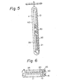
- the hinge 30 is kept horizontal and the lid member 20 is arranged linearly and horizontally with the case proper 10 without a level difference. Accordingly, if the compact case is packaged in this state, for example, with a transparent plastic film as shown in Fig. 5, the interior cosmetic 11 can be seen from the outside. Therefore, the compact case is suitably displayed for sale in the state in which the compact case is hung down from a hanging tool.
- the lid member 20 is opened by 360° so that the top face of the lid member 20 in Fig. 2 abuts with the bottom face of the case proper 10 as shown in Fig. 6.
- the compact case is packaged in this state with a transparent plastic film 40 as shown in Fig. 7, the interior cosmetic 11 can be seen from the outside and the size of the case as packaged can be made smaller than in the state shown in Fig. 5.
- the compact case is suitably displayed for sale in this state, as in Fig. 5.
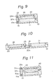
- FIGS 8 through 10 illustrate a compact case according to a second embodiment of the present invention.
- concave notches 15a and 24a formed on the rear end portions of the case proper 10 and lid member 20 do not pierce through the case proper 10 and lid member 20.
- a box-like concavity is defined by the concave notches 15a and 24a, and a hinge 30a is discretely contained in this concavity.
- the hinge 30a is connected to the first lateral pin 16 of the case proper 10 and the second lateral pin 25 of the lid member 20.
- the hinge 30a is attached to the case proper 10 and lid member 20 so that in the state where the lid 20 is closed, the hinge 30a does not project outward beyond the rear end faces of the case proper 10 and lid member 20.
- the compact case is packaged with a transparent film in the state where the lid member 20 is opened by 180° as sown in Fig. 10, the compact case is suitably displayed for sale as in the case shown in Fig. 5.
- lateral pins 16 and 25 are laid out in advance in the rear end portions of the case proper 10 and lid member 20, and the hinge 30 or 30a is fit by pressing the hinge 30 or 30a to these lateral pins 16 and 25 in the lateral direction.
- the connecting means used in the present invention are not limited to this method.
- connection of the hinge can be accomplished according to a method shown in Fig.
- this hinge 30c is located in concave notches 15 and 24 formed on the rear ends of the case proper 10 and lid member 20, and pins 16a and 25a are inserted into these small circular holes of the hinge 30c from the rear ends.
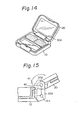
- FIGs 12 through 17 illustrate an especially preferred embodiment of the compact case according to the present invention.
- a hinge 30d has a groove 41 with which an anchoring projection 42 of the case proper 10 is engaged.
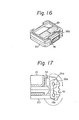
- Figures 12 and 13 show the state in which the compact case is closed. As shown in Figures 14 and 15, if the lid member 20 of the compact case is opened and rotated around a pin 25b to an angle shown in the drawings, a part of the lid member 20 abuts against a part of the hinge 30d whereby further rotation of the lid member 20 around the pin 25b is prevented. If desired, the compact case is used in this state.
- the anchoring projection 42 of the case proper 10 is disengaged from the groove 41 of the hinge 30d, the lid member 20 is rotated around a pin 16b together with the hinge 30d in the state abutting against the hinge 30d, and, finally, the lid member 20 is brought into the state rotated by 360° as shown in Figs. 16 and 17.
- An ordinary cosmetic especially a solid cosmetic such as eye shadow, rouge, or foundation, may be contained in the compact case of the present invention.
- a small makeup tool such as a brush or puff, may also be contained in the compact case.
- the hinge in the compact case of the present invention, can be discretely attached so that the hinge is not projected outward in the state where the lid member is closed, and, when the lid member is opened by 180°, the rear end portion of the lid member does not overlap the case proper and the lid member and case proper are located on the same horizontal plane. Therefore, if the compact case is packaged in this state with a transparent film, the interior cosmetic can be seen from the outside, and the compact case can be suitably displayed for sale.
- the lid member can be opened by 360° and the compact case can be packaged with a transparent film with the size of the compact case as packaged reduced. Since the compact case is displayed in the thus-packaged state, the compact case of the present invention is very convenient for stores.
Abstract
Description
- The present invention relates to a compact case comprising a case proper and a lid member, which are connected to each other through a shaft of a hinge so that the case can be optionally opened and closed.
- In a conventional compact case of this type, a concave notch is formed at the rear end portion of one of a lid member and a case proper, a hinge piece is integrally projected on the rear end portion of the other of the lid member and the case proper, and the hinge piece is inserted into the concave notch and attached to a shaft laid out in the concave notch. In this hinge structure comprising the lid member and the case proper, when the lid member is closed, the rear end face of the lid member and the rear end face of the case proper are located in the same vertical plane and the hinge portion is not projected outward. This structure is preferred from an aesthetic viewpoint. However, when the lid member is opened by 180°, the end portions of the lid member and case proper are overlapped together in the hinge portion. Generally, the lid member is not opened by 180° while it is used. Accordingly, this overlapping does not cause any trouble during use.
- A recent mode of selling compact cases is to pack the compact cases with a transparent film in the state with the lid member opened by 180° so that the cosmetic in the case proper can be seen from the outside. Such packaged compact cases are vertically hung for display. When this method is adopted, since, in case of- a conventional compact case, one of the lid member and case proper overlaps the other in the hinge portion to produce a difference in level, trouble is readily caused at the step of automatic packaging and the packaging film is readily broken. Moreover, the aesthetic effect is impaired by the presence of this difference in level.
- In another conventional compact case, a lid member is formed of a transparent plastic so the interior cosmetic can be seen from the outside even in the state where the lid member is closed and the case is packaged. In this case, a consumer can select an appropriate compact case while checking the color and the like of the interior cosmetic. However, this compact case is disadvantageous in that a mirror cannot be attached to the inner face of the lid member and thus, a user is not allowed to make up her face while viewing a mirror.
- The present invention is to overcome the foregoing defects of conventional compact cases. Namely, it is a primary object of the present invention to provide a compact case in which a hinge is not projected outward as in a conventional compact case in the state where the lid member is closed and the lid member is not overlappe on the case proper but both the lid member and the case proper are arranged on the same plane in the state where the lid member is opened by 180° and which is suitable for packaging with a transparent or semi-transparent film.
- More specifically, in accordance with the present invention, there is provided a compact case comprising a case proper and.a lid member which are connected to eac other through a hinge so that the case'is freely opened and closed, wherein concave notches communicating with each other are formed in rear end portions of the case proper and lid member, the hinge is contained in the notches so that the rear end face of the hinge is not projected outward, and the upper portion of the hinge i rotatably connected to the lid member through a first shaft and the lower portion of the hinge is rotatably connected to the case proper through a second shaft. L
-
- Figure 1 is a partially exploded perspective view of a compact case according to a first embodiment of the present invention in the state where the case is separated into respective members;
- Fig. 2 is a perspective view of the state in which the lid member is closed;
- Fig. 3 is a sectional view of the state in which the lid member is closed;
- Fig. 4 is a sectional view of the state in which the lid member is opened by 180°;
- Fig. 5 is a sectional view of the compact case which is packaged in the state opened as shown in Fig. 4 and is displayed;
- Fig. 6 is a sectional view of the state in which the case proper in the state shown in Fig. 4 is rotated by 360° in the opening direction;
- Fig. 7 is a sectional view of the compact case which is packaged in the state opened as shown in Fig. 6 and is displayed;
- Fig. 8 is a perspective view of a compact case according to a second embodiment of the present invention in the state where the lid member is closed;
- Fig. 9 is a sectional view of the state in which the lid member is closed;
- Fig. 10 is a sectional view of the state in which the lid member is opened by 180°;
- Fig. 11 is a sectional view of a compact case according to another embodiment of the present invention .in the state in which the lid member is closed;
- Fig. 12 is a perspective view of a compact case according to a preferred embodiment of the present invention in the state in which the lid member is closed;
- Fig. 13 is a sectional partial view of the state in which the lid member is closed;
- Fig. 14 is a perspective view of the state in which the lid member is opened to an intermediate anchoring position;
- Fig. 15 is a sectional partial view of the compact case in the state shown in Fig. 14;
- Fig. 16 is a perspective view of the state in which the lid member is opened by 360°; and
- Fig. 17 is a sectional partial view of the compact case in the state shown in Fig. 16.
- Figures 1 through 7 illustrate a compact case according to a first embodiment of the present invention, which comprises a case proper 10, a
lid member 20, and ahinge 30. - The case proper 10 is formed to have a substantially rectangular shape. A
recess 12 for containing a cosmetic 11 therein is formed in the central portion of the case proper 10. An L-shaped cut 13 is formed at the center of the front end face of the case proper 10 and a firstengaging projection 14 is formed on the interior face of thecut 13 integrally with the case proper 10. A first concave notch 15_piercing through the case proper 10 vertically is formed at the center of the rear end portion of the case proper 10, and alateral pin 16 is laid out at the center of thenotch 15 integrally with the case proper 10. - The
lid member 20 is formed to have a substantially rectangular shape similar to that of the case proper 10, and amirror 21 is integrally attached to the inner face of thelid member 20. Aclaw piece 22 is formed at the center of the front end of thelid member 20 so that it hangs down therefrom, and a secondengaging projection 23 is integrally formed on the inner face of theclaw piece 22. As in the case proper 10, a secondconcave notch 24 is formed in the central portion of the rear end of thelid member 20 so that thenotch 24 pierces through thelid member 20 in the vertical direction. A secondlateral pin 25 is integrally laid out at the center of thenotch 24. - The
hinge 30 is attached to the rear end portions of the case proper 10 andlid member 20 so that the case proper 10 andlid member 20 are freely openably and closably hinged together. The thickness in the front-rear direction of thehinge 30 is substantially equal to the front-rear width of thenotches lid member 20, and the height of thehinge 30 is equal to the sum of the heights of the case proper 10 andlid member 20. Upper and lower separate throughholes hinge 30. The diameters of the throughholes lateral pins Lateral slits holes holes lateral slits hinge 30 and opened in this side portion. Thehinge 30 is formed of plastic. Accordingly, the wall portion defining thelateral slits - For assembling the compact case of the first embodiment, the open end of the upper
lateral slit 33 of thehinge 30 is fit with the secondlateral pin 25 of thelid member 20, thehinge 30 is pushed to thelateral pin 25 to partially open thelateral slit 33, and the secondlateral pin 25 is fit in the throughhole 31. Similarly, thelateral pin 16 of the case proper 10 is fit with the open end of the lowerlateral slit 34 of thehinge 30, and thelateral pin 16 is pushed to fit thelateral pin 16 in the lower throughhole 32. Thus, thehinge 30 is built in the rear end portions of the case proper 10 andlid member 20, and when thelid member 20 is closed, theclaw piece 22 on the front end portion of thelid member 20 is intruded in the L-shaped cut 13 on the front end face of the case proper 10. At this point, the secondengaging projection 23 formed on the inner face of theclaw piece 22 is engaged with the firstengaging projection 14 formed on the interior face of thecut 13, and as shown in Figs. 2 and 3, thelid member 20 is located at the closed position. At this closed position, apuff 26 is preferably contained within thelid member 20. At-this closed position of thelid member 20, thehinge 30 is discretely contained within theconcave notches lid member 20, and thehinge 30 forms a smooth surface contiguous to the top and rear faces of thelid member 20 and the bottom face of the case proper 10. Accordingly, no step projecting outward is formed by thehinge 30. - In the compact case according to the first embodiment of the present invention, at the position where the
lid member 20 is opened by 180°, as shown in Fig. 4, thehinge 30 is kept horizontal and thelid member 20 is arranged linearly and horizontally with the case proper 10 without a level difference. Accordingly, if the compact case is packaged in this state, for example, with a transparent plastic film as shown in Fig. 5, the interior cosmetic 11 can be seen from the outside. Therefore, the compact case is suitably displayed for sale in the state in which the compact case is hung down from a hanging tool. Alternatively, in this compact case, thelid member 20 is opened by 360° so that the top face of thelid member 20 in Fig. 2 abuts with the bottom face of the case proper 10 as shown in Fig. 6. If the compact case is packaged in this state with atransparent plastic film 40 as shown in Fig. 7, the interior cosmetic 11 can be seen from the outside and the size of the case as packaged can be made smaller than in the state shown in Fig. 5. The compact case is suitably displayed for sale in this state, as in Fig. 5. - Figures 8 through 10 illustrate a compact case according to a second embodiment of the present invention. In this embodiment,
concave notches 15a and 24a formed on the rear end portions of the case proper 10 andlid member 20 do not pierce through the case proper 10 andlid member 20. A box-like concavity is defined by theconcave notches 15a and 24a, and a hinge 30a is discretely contained in this concavity. As in the first embodiment, the hinge 30a is connected to the firstlateral pin 16 of the case proper 10 and the secondlateral pin 25 of thelid member 20. Also in this second embodiment, the hinge 30a is attached to the case proper 10 andlid member 20 so that in the state where thelid 20 is closed, the hinge 30a does not project outward beyond the rear end faces of the case proper 10 andlid member 20. When the compact case is packaged with a transparent film in the state where thelid member 20 is opened by 180° as sown in Fig. 10, the compact case is suitably displayed for sale as in the case shown in Fig. 5. - Incidentally, in the foregoing embodiments, lateral pins 16 and 25 are laid out in advance in the rear end portions of the case proper 10 and
lid member 20, and thehinge 30 or 30a is fit by pressing thehinge 30 or 30a to theselateral pins circular holes hinge 30c, thishinge 30c is located inconcave notches lid member 20, and pins 16a and 25a are inserted into these small circular holes of thehinge 30c from the rear ends. - Figures 12 through 17 illustrate an especially preferred embodiment of the compact case according to the present invention. In this embodiment, a
hinge 30d has agroove 41 with which an anchoringprojection 42 of the case proper 10 is engaged. Figures 12 and 13 show the state in which the compact case is closed. As shown in Figures 14 and 15, if thelid member 20 of the compact case is opened and rotated around apin 25b to an angle shown in the drawings, a part of thelid member 20 abuts against a part of thehinge 30d whereby further rotation of thelid member 20 around thepin 25b is prevented. If desired, the compact case is used in this state. - If further rotation of the
lid member 20 is intended, the anchoringprojection 42 of the case proper 10 is disengaged from thegroove 41 of thehinge 30d, thelid member 20 is rotated around apin 16b together with thehinge 30d in the state abutting against thehinge 30d, and, finally, thelid member 20 is brought into the state rotated by 360° as shown in Figs. 16 and 17. - An ordinary cosmetic, especially a solid cosmetic such as eye shadow, rouge, or foundation, may be contained in the compact case of the present invention. _If desired, a small makeup tool such as a brush or puff, may also be contained in the compact case.
- As is apparent from the foregoing description, in the compact case of the present invention, the hinge can be discretely attached so that the hinge is not projected outward in the state where the lid member is closed, and, when the lid member is opened by 180°, the rear end portion of the lid member does not overlap the case proper and the lid member and case proper are located on the same horizontal plane. Therefore, if the compact case is packaged in this state with a transparent film, the interior cosmetic can be seen from the outside, and the compact case can be suitably displayed for sale.
- Especially in the case where concave notches piercing through the lid member and case proper in the' vertical direction are formed on the rear end portiors of the lid member and case proper and the hinge is attached to lateral pins of the lid member and case proper within these notches, the lid member can be opened by 360° and the compact case can be packaged with a transparent film with the size of the compact case as packaged reduced. Since the compact case is displayed in the thus-packaged state, the compact case of the present invention is very convenient for stores.
Claims (6)
- I. A compact case comprising a case proper and a lid member which are connected to each other through a hinge so that the case is freely opened and closed, wherein concave notches communicating with each other are formed in rear end portions of the case proper and lid member, the hinge is contained in the notches so that the rear end face of the hinge is not projected outward, and the upper portion of the hinge is rotatably connected to the lid member through a first shaft and the lower portion of the hinge is rotatably connected to the case proper through a second shaft.
- 2. A compact case as set forth in claim 1, wherein the notches are formed so that the notches pierce through the lid member and case proper in the rear end portions thereof in the vertical direction.
- 3. A compact case as set forth in claim 1, wherein the notches are formed so that the notches do not pierce through the lid member and case proper in the rear end portions thereof in the vertical direction.
- 4. A compact case as set forth in claim 1, wherein a first pin is integrally laid out as the first shaft in the concave notch of the lid member, a second pin is integrally laid out as the second shaft in the concave notch of the case proper, the hinge has upper and lower separate through holes, lateral slits having a longitudinal width slightly smaller than the diameter of said pins are formed in the side portions of the respective through holes, and open ends of the lateral slits are engaged with said first and second pins and the hinge is pushed to said pins, whereby the lateral slits are elastically expanded and the pins are fit in said through holes.
- 5. A compact case as set forth in claim 1, wherein a first pin is formed separately from the lid member as the first shaft, a second pin is formed separately from the case proper as the second shaft, and the hinge is contained and secured in the concave notches by said pins.
- 6. A compact case as set forth in claim 1, wherein the hinge has a groove, the groove is engaged with an anchoring projection formed on the case proper, and when the lid member is rotated around the first shaft to open the lid member, the lid member is temporarily anchored during rotation by said anchoring projection.
Applications Claiming Priority (2)
| Application Number | Priority Date | Filing Date | Title |
|---|---|---|---|
| JP1984085518U JPS612808U (en) | 1984-06-11 | 1984-06-11 | compact container |
| JP85518/84 | 1984-06-11 |
Publications (3)
| Publication Number | Publication Date |
|---|---|
| EP0165739A2 true EP0165739A2 (en) | 1985-12-27 |
| EP0165739A3 EP0165739A3 (en) | 1986-10-08 |
| EP0165739B1 EP0165739B1 (en) | 1989-03-08 |
Family
ID=13861126
Family Applications (1)
| Application Number | Title | Priority Date | Filing Date |
|---|---|---|---|
| EP85303981A Expired EP0165739B1 (en) | 1984-06-11 | 1985-06-05 | Compact case |
Country Status (5)
| Country | Link |
|---|---|
| US (1) | US4684017A (en) |
| EP (1) | EP0165739B1 (en) |
| JP (1) | JPS612808U (en) |
| KR (1) | KR910001950Y1 (en) |
| DE (1) | DE3568532D1 (en) |
Cited By (5)
| Publication number | Priority date | Publication date | Assignee | Title |
|---|---|---|---|---|
| GB2218967A (en) * | 1988-05-27 | 1989-11-29 | Helix Group Ltd | Attache case |
| FR2651975A1 (en) * | 1990-09-17 | 1991-03-22 | Yoshida Industry Co | Powder box (compact) |
| EP0574107A1 (en) * | 1992-06-08 | 1993-12-15 | Risdon Corporation | Compact with pop-up tray operated by hinged cover |
| EP0635224A1 (en) * | 1993-07-16 | 1995-01-25 | LAFFON DESIGN KREE PLAST S.p.A. | Base for containers, in particular for cosmetics products, with a movable insertand interchangeable cups |
| EP2050353A1 (en) * | 2007-10-18 | 2009-04-22 | Beaute Prestige International | Powder compact and cosmetic treatment method |
Families Citing this family (75)
| Publication number | Priority date | Publication date | Assignee | Title |
|---|---|---|---|---|
| JPH0356540Y2 (en) * | 1986-03-31 | 1991-12-19 | ||
| JPS635523U (en) * | 1986-06-30 | 1988-01-14 | ||
| GB2192666B (en) * | 1986-07-15 | 1989-12-13 | Perstorp Ab | Improvements in or relating to a nestable-stackable container |
| JPH057629Y2 (en) * | 1986-08-29 | 1993-02-25 | ||
| US4802605A (en) * | 1987-04-02 | 1989-02-07 | Gmi Engineering & Management Institute | Hinge for cable routing |
| DE3724961C1 (en) * | 1987-07-28 | 1988-09-22 | Kurz Kunststoffe Gmbh | Multi-part receptacle for several disc-shaped recording devices |
| US4744487A (en) * | 1987-09-16 | 1988-05-17 | Harmony Foods, Inc. | Food container with a hinged cover |
| US4781288A (en) * | 1987-10-13 | 1988-11-01 | Wing George S | Hermetically sealed flat case |
| JPH0750825Y2 (en) * | 1988-07-01 | 1995-11-15 | 矢崎総業株式会社 | Cover mounting structure for electrical junction box |
| US5135012A (en) * | 1988-08-29 | 1992-08-04 | Revlon, Inc. | Magnetic compact case |
| US4840288A (en) * | 1988-08-31 | 1989-06-20 | Revlon, Inc. | Compact case with irreversible hinge |
| GB2224308A (en) * | 1988-09-29 | 1990-05-02 | Systemworks Limited | Connector |
| FR2643798B1 (en) * | 1989-03-03 | 1991-07-05 | Lir France Sa | IMPROVED MAKEUP BOX |
| US5199592A (en) * | 1989-03-15 | 1993-04-06 | Perstorp Extec, Inc. | Container with latchable hinged sidewall gate |
| DE3927380A1 (en) * | 1989-08-19 | 1991-02-21 | Philips & Du Pont Optical | STORAGE CASSETTE FOR A PLATE WITH A MEDIUM HOLE |
| JPH0710654Y2 (en) * | 1989-09-18 | 1995-03-15 | 吉田工業株式会社 | Compact container |
| US5135112A (en) * | 1990-07-05 | 1992-08-04 | Melvin Kamen | Cosmetic compact case with telescopic cover and removable applicator |
| US5092354A (en) * | 1991-06-07 | 1992-03-03 | Diamond Plastics & Design, Inc. | Cosmetic kit |
| US5205142A (en) * | 1992-04-20 | 1993-04-27 | Smith & Wesson Corp. | Hinged handcuffs |
| US5437294A (en) * | 1993-03-04 | 1995-08-01 | Lir-Usa Manufacturing Co., Inc. | Compact with rotatable panel in base and/or cover |
| US5325984A (en) * | 1993-06-21 | 1994-07-05 | Motorola, Inc. | Friction clutch for dual pivot point hinge |
| DE69416280D1 (en) * | 1993-06-21 | 1999-03-11 | Motorola Inc | FRICTION COUPLING FOR A DOUBLE HINGE JOINT |
| US5431177A (en) * | 1993-11-03 | 1995-07-11 | Sussex Plastics Inc. | Compact having a window |
| US5381920A (en) * | 1993-12-21 | 1995-01-17 | Lin; Arlo H. T. | Tool box hinge structure |
| US5568820A (en) * | 1995-10-25 | 1996-10-29 | The Procter & Gamble Company | Compact case having a 360 degrees rotatable cover |
| US5692046A (en) * | 1995-11-07 | 1997-11-25 | Motorola, Inc. | Foldable telephone handset having transformable hinge |
| JP3270334B2 (en) * | 1996-07-26 | 2002-04-02 | エヌイーシーアクセステクニカ株式会社 | Hinge structure for portable electronic devices |
| US5878878A (en) * | 1997-05-07 | 1999-03-09 | Wu; Hsien-Chang | Case structure with two openable sides |
| JP3293063B2 (en) * | 1997-12-08 | 2002-06-17 | カシオ計算機株式会社 | Lid opening and closing structure |
| FR2779330B1 (en) * | 1998-06-05 | 2003-09-05 | Yoshida Kogyo Kk | COMPACT POWDER CAPABLE OF EXPOSING THE INTERIOR OF IT |
| US5979016A (en) * | 1998-08-12 | 1999-11-09 | Mustek Systems Inc. | Cover hinge structure |
| US6298541B1 (en) * | 1998-08-28 | 2001-10-09 | Becton, Dickinson And Company | Method for making a safety shield assembly and related combinations thereof |
| USD422120S (en) * | 1999-03-22 | 2000-03-28 | Cosmair Creative, Inc. | Compact |
| USD424752S (en) * | 1999-05-21 | 2000-05-09 | Tinchant Thorpe Limited | Compact case |
| US6014978A (en) * | 1999-05-28 | 2000-01-18 | Yoshida Kogyo Co., Ltd. | Compact cosmetic case capable of displaying the inside thereof |
| US6564428B2 (en) * | 2000-01-14 | 2003-05-20 | Hoffman Enclosures, Inc. | Compound hinge |
| US6500075B1 (en) * | 2000-03-06 | 2002-12-31 | Gdp, Llc | Golf training system for teaching target aim and swing path alignment |
| FR2806893B1 (en) * | 2000-03-29 | 2002-10-18 | Oreal | CASE OF THE MAKEUP CASE TYPE COMPRISING A ARTICULATED COVER |
| FR2806892B1 (en) * | 2000-03-29 | 2002-06-14 | Oreal | CASE OF THE MAKEUP CASE TYPE COMPRISING A ARTICULATED COVER |
| KR200239126Y1 (en) | 2001-02-24 | 2001-09-25 | 주식회사모토디자인 | Lipstick case |
| US7089627B2 (en) * | 2001-04-23 | 2006-08-15 | L'oreal Usa, Inc. | Magnetic hinge and device including magnetically-attracted plates |
| EP1427648B1 (en) * | 2001-08-21 | 2006-07-05 | L'Oréal USA, Inc. | Cosmetic case comprising a magnetic hinge |
| US6805257B2 (en) * | 2002-05-29 | 2004-10-19 | Craig V. Taylor | Versatile lid system |
| US20050077307A1 (en) * | 2002-05-29 | 2005-04-14 | Taylor Craig V. | Versatile lid system |
| US6859980B2 (en) | 2002-06-06 | 2005-03-01 | Austin R. Baer | Covered pinned hinge |
| FR2847778A1 (en) * | 2002-11-29 | 2004-06-04 | Techpack Int | Case/box for storing make-up product e.g. cosmetic, has composite part formed by assembly of support with hinge and panel with edge and central plate to bear product and panel interdependent of support |
| DE102004012350B3 (en) * | 2004-03-11 | 2005-07-21 | Simonswerk, Gmbh | Door strip for covered fitting between door frame and door leaf has hinge yokes serving as connecting elements |
| TWI259348B (en) * | 2004-04-06 | 2006-08-01 | Wistron Corp | Rotating structure |
| US20050258068A1 (en) * | 2004-05-21 | 2005-11-24 | Yuen-Hui Chien | Multi-medium cards case structure |
| US20060011641A1 (en) * | 2004-07-19 | 2006-01-19 | Skb Corporation | Shockrack case |
| US20080261844A1 (en) * | 2004-09-03 | 2008-10-23 | Beiersdorf Ag | Multicolor Cosmetics |
| US20060096611A1 (en) * | 2004-11-10 | 2006-05-11 | Leppla Nancy L | Show-shade cosmetic case |
| US20070234521A1 (en) * | 2006-04-06 | 2007-10-11 | Nokia Corporation | Double-axis hinge for use in electronic devices |
| US20070235466A1 (en) * | 2006-04-07 | 2007-10-11 | Fulscher Ryan L | Portable dispenser |
| US8033421B2 (en) * | 2007-10-03 | 2011-10-11 | Kimberly-Clark Worldwide, Inc. | Refillable travel dispenser for wet wipes |
| US20090100732A1 (en) * | 2007-10-19 | 2009-04-23 | Concept Workshop Worldwide, Llc | Magnetic display device |
| US8505768B2 (en) * | 2009-12-02 | 2013-08-13 | Envionmental Dining, LLC | Food tray |
| US20110247178A1 (en) * | 2010-04-11 | 2011-10-13 | Hsu Shao-Hsien | Hinge device for a toolbox |
| EP2637740B1 (en) * | 2010-11-11 | 2017-01-11 | Koninklijke Philips N.V. | Carrying case for defibrillator and accessories |
| KR101255793B1 (en) * | 2011-05-27 | 2013-04-17 | (주) 이루팩 | Cosmetic Case |
| CN202292723U (en) * | 2011-10-17 | 2012-07-04 | 上海昆杰五金工具有限公司 | Toolbox convenient for displaying tools inside |
| US9035182B2 (en) | 2013-03-15 | 2015-05-19 | Hubbell Incorporated | Floor box cover assembly |
| US8915358B2 (en) | 2013-03-29 | 2014-12-23 | Kimberly-Clark Worldwide, Inc. | Wet wipes dispenser with lid positioning feature |
| US9370227B2 (en) * | 2013-09-25 | 2016-06-21 | Eliana Ghantous | Customizable clutch with interchangeable shells and drop-in clasps |
| US9708154B2 (en) * | 2013-11-22 | 2017-07-18 | Mark Kulik | Off-road rolling film vision system |
| US9694490B2 (en) | 2014-01-05 | 2017-07-04 | Shyh-Ming Wang | Flexibly combinable tool box |
| US20150190921A1 (en) * | 2014-01-05 | 2015-07-09 | Shyh-Ming Wang | Tool box |
| CN106455792B (en) * | 2014-02-19 | 2019-10-22 | 万通集团公司 | Application member with the lid that can be used as handle |
| US9682328B2 (en) | 2014-09-11 | 2017-06-20 | Honor Metro Limited | Toy vehicle track |
| GB201418887D0 (en) * | 2014-10-23 | 2014-12-10 | Jay Mark R | Mirror assembly |
| CA2983000C (en) | 2015-04-17 | 2023-09-26 | Hubbell Incorporated | Floor box cover |
| US9816303B2 (en) * | 2016-03-16 | 2017-11-14 | Harry Kai Lee | Double axial hinge for a console |
| US20190008263A1 (en) * | 2017-07-07 | 2019-01-10 | HCT Group Holdings Limited | Wide angle compact |
| US10968673B2 (en) * | 2018-03-21 | 2021-04-06 | Microsoft Technology Licensing, Llc | Low-pressure friction hinge |
| GB2606556A (en) * | 2021-05-13 | 2022-11-16 | Nightsearcher Ltd | Portable case |
Citations (4)
| Publication number | Priority date | Publication date | Assignee | Title |
|---|---|---|---|---|
| GB275148A (en) * | 1926-07-29 | 1927-09-08 | Veit Son & Company | Improved box for powder in compressed or compact form |
| DE2135463A1 (en) * | 1971-07-15 | 1973-02-01 | Hefendehl Hansfriedrich | HAND SUITCASE |
| FR2511584A1 (en) * | 1981-08-24 | 1983-02-25 | Yoshida Industry Co | BOX |
| DE3145203A1 (en) * | 1981-11-13 | 1983-05-26 | Walter 7292 Baiersbronn Braun | Cassette for receiving elongate articles |
Family Cites Families (18)
| Publication number | Priority date | Publication date | Assignee | Title |
|---|---|---|---|---|
| DE29197C (en) * | CH. J. j bischopp in Pforzheim | Matchbox with mechanical ignition device and wind protection | ||
| US2308625A (en) * | 1939-05-12 | 1943-01-19 | Merrill L Rathbun | Closed receptacle or case |
| US2601101A (en) * | 1945-12-13 | 1952-06-17 | Victor Metal Products Corp | Hinge for molded boxes or other molded articles |
| US2546590A (en) * | 1947-10-10 | 1951-03-27 | Clyde B Ferrel | Hinge structure |
| US2829765A (en) * | 1952-12-17 | 1958-04-08 | Burger Hans Carl | Powder compact |
| US3317078A (en) * | 1965-07-29 | 1967-05-02 | Great Lakes Aluminum Fabricato | Extruded hinge |
| US3402422A (en) * | 1965-12-10 | 1968-09-24 | Austin R. Baer | Hinge |
| GB1279237A (en) * | 1968-05-10 | 1972-06-28 | John Douglas Snow | Vanity or like cases |
| CH515835A (en) * | 1970-04-24 | 1971-11-30 | Gebr Hennig Gmbh | Link track |
| JPS5216421Y2 (en) * | 1973-08-20 | 1977-04-13 | ||
| US3952369A (en) * | 1975-03-07 | 1976-04-27 | General Electric Company | Hinge structure |
| JPS5754727Y2 (en) * | 1980-08-06 | 1982-11-26 | ||
| US4372331A (en) * | 1981-05-29 | 1983-02-08 | Howard Thompson | Lipstick applicator device |
| CH653637A5 (en) * | 1981-12-17 | 1986-01-15 | Heinz Hermann Weick | PACKING FOR ORGAN towelettes. |
| US4500008A (en) * | 1982-09-22 | 1985-02-19 | Pdl Industries Limited | Weatherproof and/or dust proof fitting |
| US4588074A (en) * | 1983-08-29 | 1986-05-13 | Microsoft Corporation | Holder for storing and supporting articles |
| US4454889A (en) * | 1983-09-21 | 1984-06-19 | Contreras Sr Joseph P | Compact with air tight closure |
| US4569438A (en) * | 1985-02-04 | 1986-02-11 | Revlon, Inc. | Container having fluid-tight seal |
-
1984
- 1984-06-11 JP JP1984085518U patent/JPS612808U/en active Granted
-
1985
- 1985-06-05 EP EP85303981A patent/EP0165739B1/en not_active Expired
- 1985-06-05 DE DE8585303981T patent/DE3568532D1/en not_active Expired
- 1985-06-10 US US06/742,925 patent/US4684017A/en not_active Expired - Fee Related
- 1985-06-11 KR KR2019850006951U patent/KR910001950Y1/en not_active IP Right Cessation
Patent Citations (4)
| Publication number | Priority date | Publication date | Assignee | Title |
|---|---|---|---|---|
| GB275148A (en) * | 1926-07-29 | 1927-09-08 | Veit Son & Company | Improved box for powder in compressed or compact form |
| DE2135463A1 (en) * | 1971-07-15 | 1973-02-01 | Hefendehl Hansfriedrich | HAND SUITCASE |
| FR2511584A1 (en) * | 1981-08-24 | 1983-02-25 | Yoshida Industry Co | BOX |
| DE3145203A1 (en) * | 1981-11-13 | 1983-05-26 | Walter 7292 Baiersbronn Braun | Cassette for receiving elongate articles |
Cited By (7)
| Publication number | Priority date | Publication date | Assignee | Title |
|---|---|---|---|---|
| GB2218967A (en) * | 1988-05-27 | 1989-11-29 | Helix Group Ltd | Attache case |
| GB2218967B (en) * | 1988-05-27 | 1992-05-13 | Helix Group Ltd | Case |
| FR2651975A1 (en) * | 1990-09-17 | 1991-03-22 | Yoshida Industry Co | Powder box (compact) |
| EP0574107A1 (en) * | 1992-06-08 | 1993-12-15 | Risdon Corporation | Compact with pop-up tray operated by hinged cover |
| EP0635224A1 (en) * | 1993-07-16 | 1995-01-25 | LAFFON DESIGN KREE PLAST S.p.A. | Base for containers, in particular for cosmetics products, with a movable insertand interchangeable cups |
| EP2050353A1 (en) * | 2007-10-18 | 2009-04-22 | Beaute Prestige International | Powder compact and cosmetic treatment method |
| FR2922418A1 (en) * | 2007-10-18 | 2009-04-24 | Beaute Prestige Internat Sa | POWDER AND METHOD FOR COSMETIC TREATMENT |
Also Published As
| Publication number | Publication date |
|---|---|
| US4684017A (en) | 1987-08-04 |
| KR910001950Y1 (en) | 1991-03-30 |
| EP0165739B1 (en) | 1989-03-08 |
| EP0165739A3 (en) | 1986-10-08 |
| KR860000204U (en) | 1986-02-10 |
| DE3568532D1 (en) | 1989-04-13 |
| JPS6340164Y2 (en) | 1988-10-20 |
| JPS612808U (en) | 1986-01-09 |
Similar Documents
| Publication | Publication Date | Title |
|---|---|---|
| US4684017A (en) | Compact case | |
| US5078159A (en) | Compact case | |
| US5353947A (en) | Case having a slidable and pivotable cover | |
| US4589431A (en) | Vanity case | |
| KR102433695B1 (en) | Cosmetic vessel | |
| US6014978A (en) | Compact cosmetic case capable of displaying the inside thereof | |
| JP2001002173A (en) | Disk storage case and disk tray | |
| US2966386A (en) | Jewel box | |
| JP3051056B2 (en) | Cosmetic container | |
| JPS64813Y2 (en) | ||
| JP3497781B2 (en) | Case | |
| JPH11276243A (en) | Cosmetic compact container | |
| JPH10313937A (en) | Cosmetic container | |
| JPH0742987Y2 (en) | Product storage container | |
| JP3967463B2 (en) | Compact container for display | |
| JPS6335694Y2 (en) | ||
| JPH0131127Y2 (en) | ||
| JP3017404U (en) | Display board for golf ball box | |
| JP4227214B2 (en) | Compact container for display | |
| JPS6120967Y2 (en) | ||
| JPH0339416Y2 (en) | ||
| JP2542657Y2 (en) | Compact container | |
| JPH0519977Y2 (en) | ||
| JPH0617692Y2 (en) | Toothbrush paper case | |
| USD380485S (en) | LCD daylight projector for data and video with integrated PC |
Legal Events
| Date | Code | Title | Description |
|---|---|---|---|
| PUAI | Public reference made under article 153(3) epc to a published international application that has entered the european phase |
Free format text: ORIGINAL CODE: 0009012 |
|
| 17P | Request for examination filed |
Effective date: 19850701 |
|
| AK | Designated contracting states |
Designated state(s): CH DE FR GB IT LI |
|
| PUAL | Search report despatched |
Free format text: ORIGINAL CODE: 0009013 |
|
| AK | Designated contracting states |
Kind code of ref document: A3 Designated state(s): CH DE FR GB IT LI |
|
| 17Q | First examination report despatched |
Effective date: 19870210 |
|
| GRAA | (expected) grant |
Free format text: ORIGINAL CODE: 0009210 |
|
| AK | Designated contracting states |
Kind code of ref document: B1 Designated state(s): CH DE FR GB IT LI |
|
| REF | Corresponds to: |
Ref document number: 3568532 Country of ref document: DE Date of ref document: 19890413 |
|
| ET | Fr: translation filed | ||
| ITF | It: translation for a ep patent filed |
Owner name: BUGNION S.P.A. |
|
| PLBE | No opposition filed within time limit |
Free format text: ORIGINAL CODE: 0009261 |
|
| STAA | Information on the status of an ep patent application or granted ep patent |
Free format text: STATUS: NO OPPOSITION FILED WITHIN TIME LIMIT |
|
| 26N | No opposition filed | ||
| ITTA | It: last paid annual fee | ||
| PGFP | Annual fee paid to national office [announced via postgrant information from national office to epo] |
Ref country code: GB Payment date: 19940503 Year of fee payment: 10 |
|
| PGFP | Annual fee paid to national office [announced via postgrant information from national office to epo] |
Ref country code: FR Payment date: 19940506 Year of fee payment: 10 |
|
| PGFP | Annual fee paid to national office [announced via postgrant information from national office to epo] |
Ref country code: CH Payment date: 19940510 Year of fee payment: 10 |
|
| PGFP | Annual fee paid to national office [announced via postgrant information from national office to epo] |
Ref country code: DE Payment date: 19940613 Year of fee payment: 10 |
|
| PG25 | Lapsed in a contracting state [announced via postgrant information from national office to epo] |
Ref country code: GB Effective date: 19950605 |
|
| PG25 | Lapsed in a contracting state [announced via postgrant information from national office to epo] |
Ref country code: LI Effective date: 19950630 Ref country code: CH Effective date: 19950630 |
|
| GBPC | Gb: european patent ceased through non-payment of renewal fee |
Effective date: 19950605 |
|
| PG25 | Lapsed in a contracting state [announced via postgrant information from national office to epo] |
Ref country code: FR Effective date: 19960229 |
|
| REG | Reference to a national code |
Ref country code: CH Ref legal event code: PL |
|
| PG25 | Lapsed in a contracting state [announced via postgrant information from national office to epo] |
Ref country code: DE Effective date: 19960301 |
|
| REG | Reference to a national code |
Ref country code: FR Ref legal event code: ST |