EP0174706A2 - Enclosed pipette tip rack - Google Patents
Enclosed pipette tip rack Download PDFInfo
- Publication number
- EP0174706A2 EP0174706A2 EP19850302124 EP85302124A EP0174706A2 EP 0174706 A2 EP0174706 A2 EP 0174706A2 EP 19850302124 EP19850302124 EP 19850302124 EP 85302124 A EP85302124 A EP 85302124A EP 0174706 A2 EP0174706 A2 EP 0174706A2
- Authority
- EP
- European Patent Office
- Prior art keywords
- container
- cover
- pipette tip
- tray
- tip rack
- Prior art date
- Legal status (The legal status is an assumption and is not a legal conclusion. Google has not performed a legal analysis and makes no representation as to the accuracy of the status listed.)
- Granted
Links
Images


Classifications
-
- C—CHEMISTRY; METALLURGY
- C07—ORGANIC CHEMISTRY
- C07D—HETEROCYCLIC COMPOUNDS
- C07D401/00—Heterocyclic compounds containing two or more hetero rings, having nitrogen atoms as the only ring hetero atoms, at least one ring being a six-membered ring with only one nitrogen atom
- C07D401/02—Heterocyclic compounds containing two or more hetero rings, having nitrogen atoms as the only ring hetero atoms, at least one ring being a six-membered ring with only one nitrogen atom containing two hetero rings
- C07D401/12—Heterocyclic compounds containing two or more hetero rings, having nitrogen atoms as the only ring hetero atoms, at least one ring being a six-membered ring with only one nitrogen atom containing two hetero rings linked by a chain containing hetero atoms as chain links
-
- B—PERFORMING OPERATIONS; TRANSPORTING
- B01—PHYSICAL OR CHEMICAL PROCESSES OR APPARATUS IN GENERAL
- B01L—CHEMICAL OR PHYSICAL LABORATORY APPARATUS FOR GENERAL USE
- B01L3/00—Containers or dishes for laboratory use, e.g. laboratory glassware; Droppers
- B01L3/02—Burettes; Pipettes
- B01L3/021—Pipettes, i.e. with only one conduit for withdrawing and redistributing liquids
-
- B—PERFORMING OPERATIONS; TRANSPORTING
- B01—PHYSICAL OR CHEMICAL PROCESSES OR APPARATUS IN GENERAL
- B01L—CHEMICAL OR PHYSICAL LABORATORY APPARATUS FOR GENERAL USE
- B01L9/00—Supporting devices; Holding devices
- B01L9/54—Supports specially adapted for pipettes and burettes
- B01L9/543—Supports specially adapted for pipettes and burettes for disposable pipette tips, e.g. racks or cassettes
-
- B—PERFORMING OPERATIONS; TRANSPORTING
- B01—PHYSICAL OR CHEMICAL PROCESSES OR APPARATUS IN GENERAL
- B01L—CHEMICAL OR PHYSICAL LABORATORY APPARATUS FOR GENERAL USE
- B01L2300/00—Additional constructional details
- B01L2300/04—Closures and closing means
- B01L2300/041—Connecting closures to device or container
- B01L2300/045—Connecting closures to device or container whereby the whole cover is slidable
-
- B—PERFORMING OPERATIONS; TRANSPORTING
- B01—PHYSICAL OR CHEMICAL PROCESSES OR APPARATUS IN GENERAL
- B01L—CHEMICAL OR PHYSICAL LABORATORY APPARATUS FOR GENERAL USE
- B01L2300/00—Additional constructional details
- B01L2300/04—Closures and closing means
- B01L2300/046—Function or devices integrated in the closure
- B01L2300/048—Function or devices integrated in the closure enabling gas exchange, e.g. vents
Definitions
- This invention relates to an enclosed pipette tip rack.
- Disposable pipette tips have often been packaged in supporting trays. Such disposable pipette tip trays function to organize and to aid the user of the same in the placement of each disposable pipette tip on a pipette. Prior pipette tip trays generally had an open bottom and top. For example United States Patent 3,494,201 describes a tray or rack for disposable pipette tips and the system for use of the same.
- Packages have also been devised to ship and store stackable pipette tip racks. Such packages are intended to protect the disposable pipette tips held therewithin from any type of contamination or physical damage.
- United States Patent 3,853,217 to Scordato
- United States Patent 3,937,322 to Cohen
- French Patent 1,475,924 by way of example.
- United States design patent D 271,239 issued to Lemieux et al. describes an individual container and rack for pipette tips which does not include the provision for nesting a plurality of the same as is depicted in the prior art, e.g. in United States Patent 3,853,271 to Scorado et al.
- the container and rack for pipette tips shown in United States design patent D271,239 serves as a unitary package for disposable pipette tips and may be autoclaved. During autodaving the top of the container and rack may be tilted to allow circulation of ambient gases to the interior of the container as as shown in a brochure issued by the assignee of United States Design patent D 271,239. Open racks of the prior art are often autoclaved in cardboard boxes or metal foil containers hand fashioned for that purpose.
- a disposable enclosed pipette tip rack which solves the problems encountered in the prior art, especially during the autoclaving process, would be a great advance in the scientific and medical field.
- Another object of the present invention is to provide a pipette tip rack for holding disposable pipette tips which includes a cover which is removable and replaceable using only one hand of the person employing the pipette tip rack.
- Another object of the present invention is to provide a pipette tip rack which may be steam autoclaved and which minimizes the condensation of steam in the vicinity of the disposable tips.
- a further object of the present invention is to provide a pipette tip rack which requires a minimum of handling and therefore reduces the possibility of contamination of the pipette tips within the pipette tip rack.
- the enclosed pipette tip rack of the present invention comprises a container which has a bottom and a side wall connected to the bottom. The side wall extends outwardly and upwardly from the bottom to form a top e-dge portion.
- a tray capable of holding at least one pipette tip is supported within the container.
- a cover is provided which is supported by the container or which is indirectly supported by the tray. The cover and the container form an enclosure for the pipette tips being held by the tray.
- the pipette tip rack also includes means for venting the enclosure.
- the means for venting the enclosure may take the form of means for separating the cover from the top portion which may be in the form of an edge. Thus, a gap may be formed between the cover and the side wall of the enclosure.
- Such means for separating the cover from the top portion of the enclosure may include at least one element connected to the cover such that the container side wall would bear on same to form the ventilation gap between the top portion and the cover of the enclosure.
- at least one element may be connected to the container such that the cover bears on or rests on the same to form the heretofore described ventilation gap.
- the container and cover may each include an element.
- the cover may be positioned on the container in a first position such that the cover element is supported by the container element forming a gap between the top portion of the container and the cover. Also, the cover is capable of being positioned in a second position such that the cover engages the top portion of the container and the cover element is free of support from the element of side portion. In this configuration the gap between the top of the container and the cover will be eliminated and the enclosure would be a configura- ' tion for resisting dust intrusion.
- the pipette tip rack of the present invention may also be constructed with means for sliding the cover in relation to the top portion of the container. Consequently, the means for sliding the cover may also serve as means for separating the cover from the top portion of the container to effect ventilation of the enclosure.
- the enclosure formed by the container and the cover heretofore described, may also be vented by simply forming an opening through the enclosure itself. This may entail an opening being formed in the cover and/or the container of the enclosure formed thereby.
- a roof or overhang may be constructed to extend from the exterior of the enclosure adjacent the opening through the same.
- the tray supported by the container within the enclosure is positioned to form a first chamber between one side of the tray and the container bottom.
- a second chamber is formed between the other side of the tray and the container cover. Means are preferably provided to allow these first and second chambers to communicate with one another.
- the pipette tip, and in mbst cases a plurality of pipette tips are held in the tray by an opening or openings through the same.
- a shoulder is formed on the said other side of the tray to engage any pipette tip being held in the opening to the tray.
- the shoulder forms a space between the exterior of the pipette tip and the portion of the tray surrounding the opening therethrough. The shoulder may indeed extend into the second chamber.
- a protuberance may be formed from the portion of the tray surrounding the opening through the tray. Such a protuberance may lie between the first and second chambers and contact the exterior of the pipette tip being held in the opening through the tray. Thus, a space would also be formed between the exterior of the pipette tip and the rim of the opening in either configuration. Fluids such as air may flow between the first and second chambers formed by the tray within the container. Moreover, an opening may be formed through the tray apart from the openings employed to hold pipette tips.
- the pipette tip rack of the invention as a whole is indicated in the drawings by reference numeral 10.
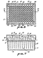
- the pipette tip rack 10 includes a container 12, as shown in Fig. 1.
- the Container 12 is constructed with a bottom 14 and a side wall 15 which, in the embodiment shown in Fig. 1, is continuous with the bottom 14 and extends upwardly therefrom.
- the Side wall 15 terminates in a top portion 16 having a top surface 18 which extends completely around the container 12.
- the container 12 may take any shape, in the embodiments shown in Figs. 1 and 2, the container 12 has a rectangular configuration with a slightly tapered side wall 15.
- the side wall 15 may include a series of projections and recesses forming a generally fluted facade 20, as shown in Fig. 2, which strengthens the container 12 and confers asthetics qualities thereto.
- the pipette tip rack 10 also includes a tray 22, as shown in Figs. 1 and 2, which tray includes means 24 for holding at least one pipette tip 26.
- Fig. 1 depicts a plurality of pipette tips 28 which are located partially within the container 12.
- the Rack 10 also includes a cover 30 which is ,supported by the container 12 above and adjacent to the tray 22.
- the cover 30 and the container 12 form an enclosure 32, indicated in Fig. 1, which encases a plurality of pipette tips 28 held in the rack 22.
- the pipette tips 28 do not touch the container bottom 14 or the cover 30 within the enclosure 32.
- the container 12 and the cover 30 forming the enclosure 32 may be constructed of any rigid or semi-rigid material.
- plastics material such as poly- proplene is preferred since it has been found that this material easily withstands a typical sterilization temperature of 132 0 C and a sterilization pressure of 1.9 kilograms per square centimeter.
- poly- proplene is resistant to chemical attack by sterilization gases such as steam, air, and ethylene oxide employed in autoclaving or other sterilization processes.
- the enclosure 32 includes means 34 for venting the same.
- the means 34 is depicted in Fig. 7 as including means 36 for separating the cover 30 from the top portion 16 of the container 12.
- a gap 38 forms between the cover 30 and the top portion 16 when rib elements 40, 42, and 44 rest on the top surface 18, as shown in Fig. 7.
- the enclosure 32 includes the said means 34 for centing the enclosure 32.
- the cover 30 may be turned approximately 180° and assume the configuration shown in Fig. 1 (second position) where the rib elements 40, 42, and 44 fit within recesses 46, 48 and 50 along the sides of the top portion 16.
- Similar ribs and recesses may also be provided along the other side 53 of the top portion 16 (only rib 55 and recess 57 shown on Fig. 2). It should be apparent that the gap 38 is not present in this second position of the cover 30 relative to the container 12. In the absence of the gap 38, the enclosed rack 10 quite adequately resists intrusion of dust and other contaminants into the interior of the enclosure 32. This "dust-free" configuration is preferred for shipping and storing of the pipette tip rack 10.
- the cover 30 also includes a raised portion 52 which fits into a depression or recess 54 in the bottom 14 of the container 12.
- racks 10, 10A and 10B may be stacked and partially nested during shipment, as indicated in Fig. 1.
- the means 34 for venting the enclosure 32 may also take the form of one or more openings through the enclosure 32, such as openings 56, 58 and 60 shown in Fig. 8.
- the opening 58 may include a roof or awning- like structure 62 to control the intrusion of dust to the interior of the enclosure 32.
- the means 34 for venting the enclosure 32 may also include an opening 64 through the cover 30, also as shown in Fig. 8.
- a container 66 includes a bottom portion 68 and,a side wall 70 extending upwardly therefrom.
- the side wall 70 includes a top portion 72 having a flange 74.
- a cover 76 includes a pair of tracks 78 and 80 forming means 82 for sliding the cover 76 in relation to the top portion 72 of the container 66.
- Fig. 13 includes directional arrows 84 and a phantom portion 86 depicting the sliding cover 76.
- a gap 88 is thus formed between the top portion 72 of the side wall 70 and the cover 76.
- the tray 22 is supported by the container 12 on a shoulder 90 which extends around the interior of the enclosed pipette tip rack 10.
- the shoulder 90 is located at a height above the bottom 14 such that the pipette tips 28 do not touch the cover 30 or the bottom 14 of the enclosure 32.
- the tray 22 forms a first chamber 92 between the underside 94 thereof and the bottom 14 and a second chamber 96 between the upper side 98 thereof and the cover 30.
- Means 100 is provided for connecting the first chamber 92 to the second chamber 96.
- the means 24 for holding each pipette tip 26 in the tray 22 comprises an opening 102 through the tray 22.
- the tray 22 includes a plurality of openings 118 therethrough each capable of holding one of the plurality of pipette tips 28.
- a quartet of shoulders or plateaus is associated with each of the plurality of openings 118 to support each of the plurality of pipette tips 28 exemplified by the pipette tip 26 in Figs. 3 and 4.
- Figs. 11 and 12 illustrate an alternate embodiment of chamber connecting means 100 used in conjunction with a pipette tip 120 which does not include a shoulder.
- Protuberances 122, 124, 126 and 128 extend from the tray 22 to contact the exterior of each pipette tip 120.
- a plurality of passages 130 are formed between successive protuberances 124, 126 and 128 permitting fluids to pass from the first chamber 92 to the second chamber 96.
- the chambers 92 and 96 may be connected by vents 132 and 134 formed by mitering the corners of the tray 22, as shown in Figs. 9 and 12.
- Fig. 6 depicts the tray 22 having each corner mitred thus forming vents 136, 138, 140 and 142.
- the Means 34 for venting the enclosure 32 may also take the form illustrated in Figs. 15 and 16 where a valve 144 is shown.
- the valve 144 is located in the cover 30 where a pair of openings 146 and 148 are provided.
- a disc 150 rotates on a pin 152 which holds the disc 150 onto the cover 30.
- the disc 150 may be rotated to open or close the openings 146 and 148 (shown closed in Fig. 15).
- a user would load the pipette tips 28 into the openings 118 of the tray 22.
- the tray 22 would be placed within the container 12 and the cover 30 - would be positioned on top of the container 12 in either the "dust-free" position, Fig. 1, or the autoclaving position, Figs. 6 and 7.
- the pipette tip rack 10 is placed in a sterilizing or autoclaving environment and fluids are free to enter and exit the pipette tip rack 10 through the venting means 34.
- such fluids are free to move between enclosure chambers 92, 96 via means 100 which may include passages adjacent each pipette tip 28 or via the openings such as vents 136, 138, 140, and 142, shown in Fig. 6.
- the cover 30 may be placed in the "dust-free" position to maintain the sterility of the pipette tips 28 within the rack 10.
- the tray 22 may be removed from the enclosure 32 when the pipette tips 28 are no longer usable. At this junction, the oover 30 and the container 12 may form a case for any desired use.
Abstract
Description
- This invention relates to an enclosed pipette tip rack.
- Disposable pipette tips have often been packaged in supporting trays. Such disposable pipette tip trays function to organize and to aid the user of the same in the placement of each disposable pipette tip on a pipette. Prior pipette tip trays generally had an open bottom and top. For example United States Patent 3,494,201 describes a tray or rack for disposable pipette tips and the system for use of the same.
- Packages have also been devised to ship and store stackable pipette tip racks. Such packages are intended to protect the disposable pipette tips held therewithin from any type of contamination or physical damage. In this respect reference is made .to United States Patent 3,853,217, to Scordato, United States Patent 3,937,322 to Cohen and French Patent 1,475,924, by way of example.
- United States design patent D 271,239 issued to Lemieux et al. describes an individual container and rack for pipette tips which does not include the provision for nesting a plurality of the same as is depicted in the prior art, e.g. in United States Patent 3,853,271 to Scorado et al. Moreover, the container and rack for pipette tips shown in United States design patent D271,239 serves as a unitary package for disposable pipette tips and may be autoclaved. During autodaving the top of the container and rack may be tilted to allow circulation of ambient gases to the interior of the container as as shown in a brochure issued by the assignee of United States Design patent D 271,239. Open racks of the prior art are often autoclaved in cardboard boxes or metal foil containers hand fashioned for that purpose.
- These prior disposable pipette tips racks and containers and the techniques employed for autoclaving the same involve undesirable aspects. For example, the method of tilting the cover on the container and rack shown in United States design patent D 271,239 is unreliable since the top is difficult to balance in a tilted position and may shift from that position during an autoclaving process. In addition, the top must be repositioned after the autoclaving process to prevent contamination from dust, moisture, and other airborne contaminants. Using a secondary container for the autoclaving is cumbersome, expensive, and often results in contamination of the disposable pipette tip in the rack during the autoclaving process.
- A disposable enclosed pipette tip rack which solves the problems encountered in the prior art, especially during the autoclaving process, would be a great advance in the scientific and medical field.
- It is an object of the present invention to provide a pipette tip rack which is fully autoclavable and permits the autoclaving gas to freely contact the pipette tips within the enclosed rack.
- It is another object of the present invention to provide a pipette tip rack which is capable of being placed in an autoclavable mode or a dust free mode depending on the position of the cover enclosing the rack.
- It is yet another object of the present invention to provide a pipette tip rack which permits free communication between first and second chambers formed by a tray which holds the disposable pipette tips within the enclosed rack.
- Another object of the present invention is to provide a pipette tip rack for holding disposable pipette tips which includes a cover which is removable and replaceable using only one hand of the person employing the pipette tip rack.
- Another object of the present invention is to provide a pipette tip rack which may be steam autoclaved and which minimizes the condensation of steam in the vicinity of the disposable tips.
- A further object of the present invention is to provide a pipette tip rack which requires a minimum of handling and therefore reduces the possibility of contamination of the pipette tips within the pipette tip rack.
- In accordance with the present invention a novel and useful enclosed pipette tip rack is provided.
- The enclosed pipette tip rack of the present invention comprises a container which has a bottom and a side wall connected to the bottom. The side wall extends outwardly and upwardly from the bottom to form a top e-dge portion. A tray capable of holding at least one pipette tip is supported within the container. Also, a cover is provided which is supported by the container or which is indirectly supported by the tray. The cover and the container form an enclosure for the pipette tips being held by the tray. The pipette tip rack also includes means for venting the enclosure.
- The means for venting the enclosure may take the form of means for separating the cover from the top portion which may be in the form of an edge. Thus, a gap may be formed between the cover and the side wall of the enclosure. Such means for separating the cover from the top portion of the enclosure may include at least one element connected to the cover such that the container side wall would bear on same to form the ventilation gap between the top portion and the cover of the enclosure. Likewise, at least one element may be connected to the container such that the cover bears on or rests on the same to form the heretofore described ventilation gap. In one embodiment, the container and cover may each include an element. In such a case the cover may be positioned on the container in a first position such that the cover element is supported by the container element forming a gap between the top portion of the container and the cover. Also, the cover is capable of being positioned in a second position such that the cover engages the top portion of the container and the cover element is free of support from the element of side portion. In this configuration the gap between the top of the container and the cover will be eliminated and the enclosure would be a configura- ' tion for resisting dust intrusion.
- The pipette tip rack of the present invention may also be constructed with means for sliding the cover in relation to the top portion of the container. Consequently, the means for sliding the cover may also serve as means for separating the cover from the top portion of the container to effect ventilation of the enclosure.
- The enclosure, formed by the container and the cover heretofore described, may also be vented by simply forming an opening through the enclosure itself. This may entail an opening being formed in the cover and/or the container of the enclosure formed thereby. A roof or overhang may be constructed to extend from the exterior of the enclosure adjacent the opening through the same.
- The tray supported by the container within the enclosure is positioned to form a first chamber between one side of the tray and the container bottom. In addition, a second chamber is formed between the other side of the tray and the container cover. Means are preferably provided to allow these first and second chambers to communicate with one another. The pipette tip, and in mbst cases a plurality of pipette tips are held in the tray by an opening or openings through the same. A shoulder is formed on the said other side of the tray to engage any pipette tip being held in the opening to the tray. The shoulder forms a space between the exterior of the pipette tip and the portion of the tray surrounding the opening therethrough. The shoulder may indeed extend into the second chamber. Similarly, a protuberance may be formed from the portion of the tray surrounding the opening through the tray. Such a protuberance may lie between the first and second chambers and contact the exterior of the pipette tip being held in the opening through the tray. Thus, a space would also be formed between the exterior of the pipette tip and the rim of the opening in either configuration. Fluids such as air may flow between the first and second chambers formed by the tray within the container. Moreover, an opening may be formed through the tray apart from the openings employed to hold pipette tips.
- The invention will be described further, by way of example, with reference to the accompanying drawings, in which:
- Fig. 1 is a sectional view of a preferred practical embodiment of the pipette tip rack of the present invention showing a second rack in phantom to illustrate the stacking feature thereof;
- Fig. 2 is a sectional view taken along line 2-2 of Fig. 1;
- Fig. 3 is an enlarged top plan view of a pair of openings occupied by pipette tips of the tray portion of the pipette tip rack depicted in Fig. 2;
- Fig. 4 is a sectional view taken along line 4-4 of Fig. 3 showing a broken side view of one pipette tip;
- Fig. 5 is an enlarged partial sectional view showing the detail of the upper edge portion of the rack depicted in Fig. 1 along line 5-5 thereof;
- Fig. 6 is a horizontal sectional view of the pipette tip rack shown in Fig. 1 emphasizing the tray portion within the rack;
- Fig. 7 is a view taken along line 7-7 of Fig. 6 showing the rack of Fig. 1 in the autoclavable mode;
- Fig. 8 is a partial sectional view showing an alternate embodiment of the ventilation means of the rack of the present invention;
- Fig. 9 is a view taken along line 9-9 of Fig. 8 depicting the ventilation means between the first and second chambers of the rack of the present invention;
- Fig. 10 is a partial sectional view showing another alternate embodiment of the ventilation means of the rack of the present invention;
- Fig. 11 is a sectional view depicting ventilation means between the first and second chambers of another embodiment of the pipette tip rack of the invention used with a pipette tip having a purely conical shape;
- Fig. 12 is a view taken along line 12-12 of Fig: 11;
- Fig. 13 is a vertical sectional view of an alternate embodiment of the pipette tip rack of the present invention having a sliding cover;
- Fig. 14 is a sectional view taken along line 14-14 of Fig. 13;
- . Fig. 15 is a perspective view of another embodiment of the pipette tip rack of the present invention; and
- Fig. 16 is a sectional view taken along line 16-16 of Fig. 15.
- The pipette tip rack of the invention as a whole is indicated in the drawings by
reference numeral 10. Thepipette tip rack 10 includes acontainer 12, as shown in Fig. 1. TheContainer 12 is constructed with a bottom 14 and aside wall 15 which, in the embodiment shown in Fig. 1, is continuous with the bottom 14 and extends upwardly therefrom. TheSide wall 15 terminates in atop portion 16 having atop surface 18 which extends completely around thecontainer 12. Although thecontainer 12 may take any shape, in the embodiments shown in Figs. 1 and 2, thecontainer 12 has a rectangular configuration with a slightly taperedside wall 15. Theside wall 15 may include a series of projections and recesses forming a generally flutedfacade 20, as shown in Fig. 2, which strengthens thecontainer 12 and confers asthetics qualities thereto. - The
pipette tip rack 10 also includes atray 22, as shown in Figs. 1 and 2, which tray includes means 24 for holding at least onepipette tip 26. By way of illustration Fig. 1 depicts a plurality ofpipette tips 28 which are located partially within thecontainer 12. - The
Rack 10 also includes acover 30 which is ,supported by thecontainer 12 above and adjacent to thetray 22. Thecover 30 and thecontainer 12 form anenclosure 32, indicated in Fig. 1, which encases a plurality ofpipette tips 28 held in therack 22. Thepipette tips 28 do not touch the container bottom 14 or thecover 30 within theenclosure 32. Thecontainer 12 and thecover 30 forming theenclosure 32 may be constructed of any rigid or semi-rigid material. However, plastics material such as poly- proplene is preferred since it has been found that this material easily withstands a typical sterilization temperature of 1320C and a sterilization pressure of 1.9 kilograms per square centimeter. Also, poly- proplene is resistant to chemical attack by sterilization gases such as steam, air, and ethylene oxide employed in autoclaving or other sterilization processes. - The
enclosure 32 includesmeans 34 for venting the same. The means 34 is depicted in Fig. 7 as including means 36 for separating thecover 30 from thetop portion 16 of thecontainer 12. Agap 38 forms between thecover 30 and thetop portion 16 whenrib elements top surface 18, as shown in Fig. 7. When thecover 30 is positioned as shown in Fig. 7 (first position) theenclosure 32 includes the said means 34 for centing theenclosure 32. On the other hand,thecover 30 may be turned approximately 180° and assume the configuration shown in Fig. 1 (second position) where therib elements recesses top portion 16. Similar ribs and recesses may also be provided along the other side 53 of the top portion 16 (onlyrib 55 and recess 57 shown on Fig. 2). It should be apparent that thegap 38 is not present in this second position of thecover 30 relative to thecontainer 12. In the absence of thegap 38, theenclosed rack 10 quite adequately resists intrusion of dust and other contaminants into the interior of theenclosure 32. This "dust-free" configuration is preferred for shipping and storing of thepipette tip rack 10. - The
cover 30 also includes a raisedportion 52 which fits into a depression orrecess 54 in the bottom 14 of thecontainer 12. Thus, racks 10, 10A and 10B may be stacked and partially nested during shipment, as indicated in Fig. 1. - The means 34 for venting the
enclosure 32 may also take the form of one or more openings through theenclosure 32, such asopenings opening 58 may include a roof or awning-like structure 62 to control the intrusion of dust to the interior of theenclosure 32. The means 34 for venting theenclosure 32 may also include anopening 64 through thecover 30, also as shown in Fig. 8. - The means 34 for venting the
enclosure 32 and the means for separating thecover 30 from thecontainer 12 may also take the form shown in the embodiment of Figs. 13 and 14. In this embodiment acontainer 66 includes abottom portion 68 and,aside wall 70 extending upwardly therefrom. Theside wall 70 includes atop portion 72 having aflange 74. Acover 76 includes a pair oftracks means 82 for sliding thecover 76 in relation to thetop portion 72 of thecontainer 66. Fig. 13 includesdirectional arrows 84 and aphantom portion 86 depicting the slidingcover 76. A gap 88 is thus formed between thetop portion 72 of theside wall 70 and thecover 76. - Returning to Fig. 1 it may be seen that the
tray 22 is supported by thecontainer 12 on ashoulder 90 which extends around the interior of the enclosedpipette tip rack 10. Theshoulder 90 is located at a height above the bottom 14 such that thepipette tips 28 do not touch thecover 30 or the bottom 14 of theenclosure 32. Thetray 22 forms afirst chamber 92 between theunderside 94 thereof and the bottom 14 and a second chamber 96 between theupper side 98 thereof and thecover 30.Means 100 is provided for connecting thefirst chamber 92 to the second chamber 96. With reference to Figs. 3 and 4, it may'be seen that themeans 24 for holding eachpipette tip 26 in thetray 22 comprises anopening 102 through thetray 22. Shoulders or plateaus 104, 106, 108 and 110 extend upwardly from theupper side 98 of thetray 22 and engage anannulus 112 of eachpipette tip 126. Consequently a multiplicity offluid passages 103 are formed betweenadjacent shoulders second chambers 92 and 96 as perdirectional arrows tray 22 includes a plurality ofopenings 118 therethrough each capable of holding one of the plurality ofpipette tips 28. A quartet of shoulders or plateaus is associated with each of the plurality ofopenings 118 to support each of the plurality ofpipette tips 28 exemplified by thepipette tip 26 in Figs. 3 and 4. - Figs. 11 and 12 illustrate an alternate embodiment of chamber connecting means 100 used in conjunction with a
pipette tip 120 which does not include a shoulder.Protuberances tray 22 to contact the exterior of eachpipette tip 120. Thus, a plurality ofpassages 130 are formed betweensuccessive protuberances first chamber 92 to the second chamber 96. In addition, thechambers 92 and 96 may be connected byvents tray 22, as shown in Figs. 9 and 12. Fig. 6 depicts thetray 22 having each corner mitred thus formingvents - The
Means 34 for venting theenclosure 32 may also take the form illustrated in Figs. 15 and 16 where avalve 144 is shown. Thevalve 144 is located in thecover 30 where a pair ofopenings disc 150 rotates on apin 152 which holds thedisc 150 onto thecover 30. Thus, thedisc 150 may be rotated to open or close theopenings 146 and 148 (shown closed in Fig. 15). - In operation, a user would load the
pipette tips 28 into theopenings 118 of thetray 22. Thetray 22 would be placed within thecontainer 12 and thecover 30-would be positioned on top of thecontainer 12 in either the "dust-free" position, Fig. 1, or the autoclaving position, Figs. 6 and 7. In the latter position thepipette tip rack 10 is placed in a sterilizing or autoclaving environment and fluids are free to enter and exit thepipette tip rack 10 through the venting means 34. In addition, such fluids are free to move betweenenclosure chambers 92, 96 viameans 100 which may include passages adjacent eachpipette tip 28 or via the openings such asvents cover 30 may be placed in the "dust-free" position to maintain the sterility of thepipette tips 28 within therack 10. - The
tray 22 may be removed from theenclosure 32 when thepipette tips 28 are no longer usable. At this junction, theoover 30 and thecontainer 12 may form a case for any desired use. - While in the foregoing embodiments of the present invention have been set forth in the considerable detail for the purposes of making a complete disclosure of the invention, it may be apparent to those of skill in the art that numerous changes may be made in the details without departing from the scope of the invention.
Claims (16)
Priority Applications (1)
| Application Number | Priority Date | Filing Date | Title |
|---|---|---|---|
| AT85302124T ATE67105T1 (en) | 1984-09-14 | 1985-03-27 | CLOSED CONTAINER FOR PIPETTE TIPS. |
Applications Claiming Priority (2)
| Application Number | Priority Date | Filing Date | Title |
|---|---|---|---|
| US650505 | 1984-09-14 | ||
| US06/650,505 US4577760A (en) | 1984-09-14 | 1984-09-14 | Apparatus for supporting pipette tips |
Publications (3)
| Publication Number | Publication Date |
|---|---|
| EP0174706A2 true EP0174706A2 (en) | 1986-03-19 |
| EP0174706A3 EP0174706A3 (en) | 1988-01-13 |
| EP0174706B1 EP0174706B1 (en) | 1991-09-11 |
Family
ID=24609206
Family Applications (1)
| Application Number | Title | Priority Date | Filing Date |
|---|---|---|---|
| EP85302124A Expired - Lifetime EP0174706B1 (en) | 1984-09-14 | 1985-03-27 | Enclosed pipette tip rack |
Country Status (5)
| Country | Link |
|---|---|
| US (1) | US4577760A (en) |
| EP (1) | EP0174706B1 (en) |
| JP (1) | JPS6174652A (en) |
| AT (1) | ATE67105T1 (en) |
| DE (1) | DE3584060D1 (en) |
Cited By (13)
| Publication number | Priority date | Publication date | Assignee | Title |
|---|---|---|---|---|
| EP0339557A2 (en) * | 1988-04-25 | 1989-11-02 | Brand GmbH + Co | Device for providing sterilized pipette tips |
| DE9006918U1 (en) * | 1990-06-20 | 1990-08-23 | Walter Sarstedt Geraete Und Verbrauchsmaterial Fuer Medizin Und Wissenschaft, 5223 Nuembrecht, De | |
| WO1992001514A1 (en) * | 1990-07-21 | 1992-02-06 | Gert Schiedel | Refilling unit with pipette tips seated in a detachable holding device for an autoclavable container |
| DE9203565U1 (en) * | 1992-03-17 | 1992-05-07 | Greiner Gmbh, 7440 Nuertingen, De | |
| DE4208503C1 (en) * | 1992-03-17 | 1993-07-15 | Greiner Gmbh, 7440 Nuertingen, De | Pipette point sterilising container - has sliding locking lids and perforated plates to hold pipette points alternately up and down |
| WO1994012279A1 (en) * | 1992-12-01 | 1994-06-09 | Technic Limited | Device for handling and transferring pipette tips |
| DE4240280A1 (en) * | 1992-12-01 | 1994-06-09 | Bernd Dr Steinbrenner | Reusable pipette tip holding container - for autoclave treatment pref. sterilisation of pipette tips |
| DE4240315A1 (en) * | 1992-12-01 | 1994-07-14 | Bernd Dr Steinbrenner | Device for handling and transferring pipette tips |
| DE4329791A1 (en) * | 1993-09-03 | 1995-03-30 | Teja Lichtenberg | Method and device for automatic distribution of microfilter discs |
| WO1995021696A1 (en) * | 1994-02-15 | 1995-08-17 | Point Plastics Incorporated | Pipette tip mounting and transfer apparatus and method |
| DE19525258A1 (en) * | 1995-07-11 | 1997-01-16 | Bernd Dr Steinbrenner | Laboratory box for pipette tips or reaction vessels - has sliding cover moving longitudinally or laterally |
| US5882603A (en) * | 1997-10-15 | 1999-03-16 | Point Plastics Incorporated | Support rack for pipette tips |
| CN102923382A (en) * | 2012-11-06 | 2013-02-13 | 无锡耐思生物科技有限公司 | Locking structure of instrument head box of liquid-transferring instrument |
Families Citing this family (38)
| Publication number | Priority date | Publication date | Assignee | Title |
|---|---|---|---|---|
| US4676377A (en) * | 1984-09-14 | 1987-06-30 | Rainin Instrument Co., Inc. | Enclosed pipette tip rack |
| US4726466A (en) * | 1985-08-19 | 1988-02-23 | Aims Biotech Corporation | Hypodermic needle protection device |
| US4772418A (en) * | 1986-10-01 | 1988-09-20 | Nalge Company | Autoclavable rack container |
| US4980293A (en) * | 1988-09-02 | 1990-12-25 | Multi-Technology Inc. | Dispensing reagents in a specimen well |
| AT399704B (en) * | 1991-10-01 | 1995-07-25 | Haas Franz Waffelmasch | CONTAINER MADE OF EASILY ROTABLE MATERIAL |
| US5441702A (en) * | 1993-09-21 | 1995-08-15 | Rainin Instrument Co., Inc. | Refill pack for pipette tip racks |
| DE69409629T2 (en) * | 1993-09-21 | 1998-11-05 | Rainin Instr Co Inc | REFILL FOR PIPETTE TIP CONTAINERS |
| WO1995033564A1 (en) * | 1994-06-03 | 1995-12-14 | Labcon, North America | Pipette tip rack loader |
| US5470538A (en) * | 1994-06-03 | 1995-11-28 | Labcon, North America | Pipette tip rack loader |
| US5674047A (en) * | 1995-07-13 | 1997-10-07 | Chiron Diagnostics Corporation | Loading mechanism for probe tip tray |
| CA2287962C (en) | 1997-05-02 | 2007-01-02 | Gen-Probe Incorporated | Reaction receptacle apparatus |
| US5922289A (en) * | 1997-12-05 | 1999-07-13 | Evergreen Industries Inc. | Microtitration tray |
| FR2784076B1 (en) * | 1998-10-06 | 2000-12-22 | Gilson Sa | ASSEMBLY INCLUDING STACKED PIPETTE CONE REFILLS |
| US6019225A (en) * | 1998-10-26 | 2000-02-01 | Matrix Technologies Corp. | Pipette tip rack with array of interconnected sleeves |
| US6098802A (en) * | 1998-12-17 | 2000-08-08 | Michael Hoffman | Deep well rack assembly for pipette tips and the like |
| US6426047B1 (en) * | 1999-02-01 | 2002-07-30 | Matrix Technologies Corporations | Disposable tip magazine |
| US6875405B1 (en) | 1999-02-01 | 2005-04-05 | Matrix Technologies Corporation | Tube rack |
| US6221317B1 (en) * | 1999-04-30 | 2001-04-24 | Ccs Packard, Inc. | Universal pipette tip box |
| US7169361B2 (en) * | 2002-01-10 | 2007-01-30 | Molecular Bioproducts, Inc. | Pipette tip reloading system |
| CA2483445C (en) | 2002-04-26 | 2011-04-19 | Abbott Laboratories | Structure and method for handling magnetic particles in biological assays |
| US7846269B2 (en) * | 2004-09-24 | 2010-12-07 | Munchkin, Inc. | Feeding straw holders for dishwasher |
| WO2010008737A2 (en) * | 2008-06-17 | 2010-01-21 | Pelican Group Holdings, Inc. | Antimicrobial fluid handling devices and methods of manufacture |
| EP2389247B1 (en) | 2009-01-23 | 2017-03-01 | Biotix, Inc. | Anti-static pipette tip trays |
| USD638953S1 (en) | 2009-05-12 | 2011-05-31 | Invitrogen Dynal As | Laboratory apparatus |
| RU2456220C1 (en) * | 2011-04-13 | 2012-07-20 | Государственное образовательное учреждение высшего профессионального образования "Курский государственный медицинский университет Министерства здравоохранения и социального развития Российской Федерации" | Method for slide fixation in cartridge |
| US9848753B2 (en) | 2013-08-13 | 2017-12-26 | Munchkin, Inc. | Dishwasher basket with adjustable tray |
| JP6215166B2 (en) * | 2014-09-26 | 2017-10-18 | デンタルプロ株式会社 | Interdental brush case |
| USD849962S1 (en) | 2014-12-10 | 2019-05-28 | Biotix, Inc. | Pipette tip retention sheet |
| USD865216S1 (en) | 2014-12-10 | 2019-10-29 | Biotix, Inc. | Pipette tip sheet |
| US10137453B2 (en) | 2014-12-10 | 2018-11-27 | Biotix, Inc. | Static-defeating apparatus for pipette tips |
| US10730053B2 (en) | 2014-12-10 | 2020-08-04 | Biotix, Inc. | Static-defeating apparatus for pipette tips |
| USD815753S1 (en) | 2014-12-10 | 2018-04-17 | Biotix, Inc. | Pipette tip sheet |
| CN110461475B (en) | 2017-02-03 | 2021-11-16 | 拜欧迪克斯公司 | Efficient nested pipette tip array and related methods |
| US11274978B2 (en) * | 2017-11-01 | 2022-03-15 | Medline Industries Lp | Tapered thermal probe cover and corresponding packaging system |
| USD888280S1 (en) | 2018-03-29 | 2020-06-23 | Biotix, Inc. | Pipette tip tray |
| JP6694486B2 (en) * | 2018-03-29 | 2020-05-13 | バイオティクス, インコーポレイテッド | Pipette tip tray with increased rigidity |
| USD923816S1 (en) | 2019-03-20 | 2021-06-29 | Biotix, Inc. | Pipette tip tray |
| USD905267S1 (en) * | 2019-03-27 | 2020-12-15 | Avidien Technologies, Inc. | Pipette tip adapter |
Citations (5)
| Publication number | Priority date | Publication date | Assignee | Title |
|---|---|---|---|---|
| US3937322A (en) * | 1971-06-17 | 1976-02-10 | Medical Laboratory Automation, Inc. | Package for disposable pipette tips |
| US4256240A (en) * | 1978-11-01 | 1981-03-17 | Innovative Design Company Pty. Limited | Container closure |
| US4349109A (en) * | 1980-10-20 | 1982-09-14 | Medical Laboratory Automation, Inc. | Disposable pipette tips and trays therefor |
| US4358908A (en) * | 1980-12-23 | 1982-11-16 | Song John S | Plant culture vessel |
| US4436700A (en) * | 1980-08-11 | 1984-03-13 | The Board Of Regents Of The University Of Nebraska | Autoclavable pipette jar and method of using it |
Family Cites Families (9)
| Publication number | Priority date | Publication date | Assignee | Title |
|---|---|---|---|---|
| US3082904A (en) * | 1959-12-15 | 1963-03-26 | American Can Co | Container |
| FR1475924A (en) * | 1966-02-24 | 1967-04-07 | Cease Central | Packaging for ready meals with a serving tray |
| US3381872A (en) * | 1966-05-18 | 1968-05-07 | Monsanto Co | Sanitary packages |
| US3494201A (en) * | 1968-08-16 | 1970-02-10 | Oxford Lab | Pipetting system |
| US3853217A (en) * | 1972-08-09 | 1974-12-10 | Medical Laboratory Automation | Pipette tip package |
| US4399159A (en) * | 1978-12-20 | 1983-08-16 | Sunset Ltd. | Vertable tray and lid assembly for heating foods |
| US4235338A (en) * | 1979-04-20 | 1980-11-25 | Owens-Illinois, Inc. | Unitary molded container lid and tray for article packaging |
| CA1117071A (en) * | 1979-05-25 | 1982-01-26 | Jean-Marie Chabot | Container lid |
| JPS5986240U (en) * | 1982-11-30 | 1984-06-11 | 篠田 勝幸 | Cleaner for the tip of a metering pipette |
-
1984
- 1984-09-14 US US06/650,505 patent/US4577760A/en not_active Expired - Fee Related
-
1985
- 1985-03-27 DE DE8585302124T patent/DE3584060D1/en not_active Expired - Fee Related
- 1985-03-27 AT AT85302124T patent/ATE67105T1/en not_active IP Right Cessation
- 1985-03-27 EP EP85302124A patent/EP0174706B1/en not_active Expired - Lifetime
- 1985-05-13 JP JP60101170A patent/JPS6174652A/en active Granted
Patent Citations (5)
| Publication number | Priority date | Publication date | Assignee | Title |
|---|---|---|---|---|
| US3937322A (en) * | 1971-06-17 | 1976-02-10 | Medical Laboratory Automation, Inc. | Package for disposable pipette tips |
| US4256240A (en) * | 1978-11-01 | 1981-03-17 | Innovative Design Company Pty. Limited | Container closure |
| US4436700A (en) * | 1980-08-11 | 1984-03-13 | The Board Of Regents Of The University Of Nebraska | Autoclavable pipette jar and method of using it |
| US4349109A (en) * | 1980-10-20 | 1982-09-14 | Medical Laboratory Automation, Inc. | Disposable pipette tips and trays therefor |
| US4358908A (en) * | 1980-12-23 | 1982-11-16 | Song John S | Plant culture vessel |
Cited By (16)
| Publication number | Priority date | Publication date | Assignee | Title |
|---|---|---|---|---|
| EP0339557A2 (en) * | 1988-04-25 | 1989-11-02 | Brand GmbH + Co | Device for providing sterilized pipette tips |
| EP0339557A3 (en) * | 1988-04-25 | 1990-10-03 | Gert Schiedel | Pipette tip reloading unit for a sterilization container |
| DE9006918U1 (en) * | 1990-06-20 | 1990-08-23 | Walter Sarstedt Geraete Und Verbrauchsmaterial Fuer Medizin Und Wissenschaft, 5223 Nuembrecht, De | |
| WO1992001514A1 (en) * | 1990-07-21 | 1992-02-06 | Gert Schiedel | Refilling unit with pipette tips seated in a detachable holding device for an autoclavable container |
| DE9203565U1 (en) * | 1992-03-17 | 1992-05-07 | Greiner Gmbh, 7440 Nuertingen, De | |
| DE4208503C1 (en) * | 1992-03-17 | 1993-07-15 | Greiner Gmbh, 7440 Nuertingen, De | Pipette point sterilising container - has sliding locking lids and perforated plates to hold pipette points alternately up and down |
| DE4240315A1 (en) * | 1992-12-01 | 1994-07-14 | Bernd Dr Steinbrenner | Device for handling and transferring pipette tips |
| DE4240280A1 (en) * | 1992-12-01 | 1994-06-09 | Bernd Dr Steinbrenner | Reusable pipette tip holding container - for autoclave treatment pref. sterilisation of pipette tips |
| WO1994012279A1 (en) * | 1992-12-01 | 1994-06-09 | Technic Limited | Device for handling and transferring pipette tips |
| DE4329791A1 (en) * | 1993-09-03 | 1995-03-30 | Teja Lichtenberg | Method and device for automatic distribution of microfilter discs |
| WO1995021696A1 (en) * | 1994-02-15 | 1995-08-17 | Point Plastics Incorporated | Pipette tip mounting and transfer apparatus and method |
| US5487997A (en) * | 1994-02-15 | 1996-01-30 | Point Plastics Incorporated | Pipette tip mounting and transfer apparatus and method |
| US5630988A (en) * | 1994-02-15 | 1997-05-20 | Point Plastics Inc. | Pipette tip mounting and transfer apparatus |
| DE19525258A1 (en) * | 1995-07-11 | 1997-01-16 | Bernd Dr Steinbrenner | Laboratory box for pipette tips or reaction vessels - has sliding cover moving longitudinally or laterally |
| US5882603A (en) * | 1997-10-15 | 1999-03-16 | Point Plastics Incorporated | Support rack for pipette tips |
| CN102923382A (en) * | 2012-11-06 | 2013-02-13 | 无锡耐思生物科技有限公司 | Locking structure of instrument head box of liquid-transferring instrument |
Also Published As
| Publication number | Publication date |
|---|---|
| EP0174706A3 (en) | 1988-01-13 |
| JPS6174652A (en) | 1986-04-16 |
| US4577760A (en) | 1986-03-25 |
| ATE67105T1 (en) | 1991-09-15 |
| JPH037419B2 (en) | 1991-02-01 |
| EP0174706B1 (en) | 1991-09-11 |
| DE3584060D1 (en) | 1991-10-17 |
Similar Documents
| Publication | Publication Date | Title |
|---|---|---|
| EP0174706A2 (en) | Enclosed pipette tip rack | |
| US4676377A (en) | Enclosed pipette tip rack | |
| US6019225A (en) | Pipette tip rack with array of interconnected sleeves | |
| US5993745A (en) | Archival storage tray for multiple test tubes | |
| US4589551A (en) | Container for handling, transportation and storage of microscope slides | |
| JP3179679B2 (en) | Plastic container | |
| US4599314A (en) | Multiple vessel specimen tray with lid for releasably adhering vessel covers | |
| US4880116A (en) | Robotic accessible wafer shipper assembly | |
| US7658887B2 (en) | Pipette tip grid with lock mechanism | |
| US5344023A (en) | Egg container assembly | |
| DK172123B1 (en) | Multiple compartment culture device for culture and with means for reducing the evaporation of culture substrate. | |
| RU2579742C2 (en) | Package for containers | |
| US9968695B2 (en) | Medical instrument sterilization system and method | |
| US4772418A (en) | Autoclavable rack container | |
| US5856176A (en) | Culture dish | |
| US6918738B2 (en) | Stackable sample holding plate with robot removable lid | |
| JP2002234586A (en) | Cassette arrangement for housing box, etc., in particular, petri dish | |
| US20220371760A1 (en) | Sterilizing packaging units | |
| CN219097317U (en) | Storage container for cover glass | |
| US20240043170A1 (en) | Spacer Structure for Separating Two Stacked Tubs Configured for the Storage and/or Transport of a Plurality of Medical Containers, and a Packaging Including Said Spacer Structure | |
| US6851772B2 (en) | Closure for selectively closing a container | |
| KR200391441Y1 (en) | Vacuum cover | |
| US20050035024A1 (en) | Food holding containers | |
| JPH05236934A (en) | Culturing vessel |
Legal Events
| Date | Code | Title | Description |
|---|---|---|---|
| PUAI | Public reference made under article 153(3) epc to a published international application that has entered the european phase |
Free format text: ORIGINAL CODE: 0009012 |
|
| AK | Designated contracting states |
Kind code of ref document: A2 Designated state(s): AT BE CH DE FR GB IT LI LU NL SE |
|
| 17P | Request for examination filed |
Effective date: 19860619 |
|
| PUAL | Search report despatched |
Free format text: ORIGINAL CODE: 0009013 |
|
| AK | Designated contracting states |
Kind code of ref document: A3 Designated state(s): AT BE CH DE FR GB IT LI LU NL SE |
|
| 17Q | First examination report despatched |
Effective date: 19890628 |
|
| DIN1 | Information on inventor provided before grant (deleted) | ||
| RAP1 | Party data changed (applicant data changed or rights of an application transferred) |
Owner name: RAININ INSTRUMENT CO.,INC. |
|
| RIN1 | Information on inventor provided before grant (corrected) |
Inventor name: RUSKEWICZ, STEPHEN Inventor name: RAININ, KENNETH |
|
| GRAA | (expected) grant |
Free format text: ORIGINAL CODE: 0009210 |
|
| AK | Designated contracting states |
Kind code of ref document: B1 Designated state(s): AT BE CH DE FR GB IT LI LU NL SE |
|
| REF | Corresponds to: |
Ref document number: 67105 Country of ref document: AT Date of ref document: 19910915 Kind code of ref document: T |
|
| ET | Fr: translation filed | ||
| REF | Corresponds to: |
Ref document number: 3584060 Country of ref document: DE Date of ref document: 19911017 |
|
| ITF | It: translation for a ep patent filed |
Owner name: PATRITO BREVETTI |
|
| PGFP | Annual fee paid to national office [announced via postgrant information from national office to epo] |
Ref country code: CH Payment date: 19920324 Year of fee payment: 8 |
|
| PG25 | Lapsed in a contracting state [announced via postgrant information from national office to epo] |
Ref country code: AT Effective date: 19920327 |
|
| PG25 | Lapsed in a contracting state [announced via postgrant information from national office to epo] |
Ref country code: SE Effective date: 19920328 |
|
| PG25 | Lapsed in a contracting state [announced via postgrant information from national office to epo] |
Ref country code: LU Free format text: LAPSE BECAUSE OF NON-PAYMENT OF DUE FEES Effective date: 19920331 Ref country code: BE Effective date: 19920331 |
|
| PLBE | No opposition filed within time limit |
Free format text: ORIGINAL CODE: 0009261 |
|
| STAA | Information on the status of an ep patent application or granted ep patent |
Free format text: STATUS: NO OPPOSITION FILED WITHIN TIME LIMIT |
|
| 26N | No opposition filed | ||
| BERE | Be: lapsed |
Owner name: RAININ INSTRUMENT CO. INC. Effective date: 19920331 |
|
| PG25 | Lapsed in a contracting state [announced via postgrant information from national office to epo] |
Ref country code: NL Effective date: 19921001 |
|
| NLV4 | Nl: lapsed or anulled due to non-payment of the annual fee | ||
| PGFP | Annual fee paid to national office [announced via postgrant information from national office to epo] |
Ref country code: GB Payment date: 19930317 Year of fee payment: 9 Ref country code: FR Payment date: 19930317 Year of fee payment: 9 |
|
| PGFP | Annual fee paid to national office [announced via postgrant information from national office to epo] |
Ref country code: DE Payment date: 19930320 Year of fee payment: 9 |
|
| PG25 | Lapsed in a contracting state [announced via postgrant information from national office to epo] |
Ref country code: LI Effective date: 19930331 Ref country code: CH Effective date: 19930331 |
|
| REG | Reference to a national code |
Ref country code: CH Ref legal event code: PL |
|
| PG25 | Lapsed in a contracting state [announced via postgrant information from national office to epo] |
Ref country code: GB Effective date: 19940327 |
|
| GBPC | Gb: european patent ceased through non-payment of renewal fee |
Effective date: 19940327 |
|
| PG25 | Lapsed in a contracting state [announced via postgrant information from national office to epo] |
Ref country code: FR Effective date: 19941130 |
|
| PG25 | Lapsed in a contracting state [announced via postgrant information from national office to epo] |
Ref country code: DE Effective date: 19941201 |
|
| REG | Reference to a national code |
Ref country code: FR Ref legal event code: ST |
|
| EUG | Se: european patent has lapsed |
Ref document number: 85302124.4 Effective date: 19921005 |