EP0180558A2 - An industrial robot having two gimbal-ring type arranged swinging axes - Google Patents
An industrial robot having two gimbal-ring type arranged swinging axes Download PDFInfo
- Publication number
- EP0180558A2 EP0180558A2 EP85850154A EP85850154A EP0180558A2 EP 0180558 A2 EP0180558 A2 EP 0180558A2 EP 85850154 A EP85850154 A EP 85850154A EP 85850154 A EP85850154 A EP 85850154A EP 0180558 A2 EP0180558 A2 EP 0180558A2
- Authority
- EP
- European Patent Office
- Prior art keywords
- platform
- gimbal
- motor
- ring type
- arm
- Prior art date
- Legal status (The legal status is an assumption and is not a legal conclusion. Google has not performed a legal analysis and makes no representation as to the accuracy of the status listed.)
- Granted
Links
Images

Classifications
-
- B—PERFORMING OPERATIONS; TRANSPORTING
- B25—HAND TOOLS; PORTABLE POWER-DRIVEN TOOLS; MANIPULATORS
- B25J—MANIPULATORS; CHAMBERS PROVIDED WITH MANIPULATION DEVICES
- B25J17/00—Joints
- B25J17/02—Wrist joints
- B25J17/0258—Two-dimensional joints
-
- B—PERFORMING OPERATIONS; TRANSPORTING
- B25—HAND TOOLS; PORTABLE POWER-DRIVEN TOOLS; MANIPULATORS
- B25J—MANIPULATORS; CHAMBERS PROVIDED WITH MANIPULATION DEVICES
- B25J18/00—Arms
- B25J18/02—Arms extensible
- B25J18/025—Arms extensible telescopic
-
- B—PERFORMING OPERATIONS; TRANSPORTING
- B25—HAND TOOLS; PORTABLE POWER-DRIVEN TOOLS; MANIPULATORS
- B25J—MANIPULATORS; CHAMBERS PROVIDED WITH MANIPULATION DEVICES
- B25J9/00—Programme-controlled manipulators
- B25J9/02—Programme-controlled manipulators characterised by movement of the arms, e.g. cartesian coordinate type
- B25J9/04—Programme-controlled manipulators characterised by movement of the arms, e.g. cartesian coordinate type by rotating at least one arm, excluding the head movement itself, e.g. cylindrical coordinate type or polar coordinate type
- B25J9/048—Pendulum type
Definitions
- the present invention relates to an industrial robot having a global-ring type suspended part which can be swung about two mutually perpendicular axes by means of a first and a second motor, there being arranged in the gimbal-ring type suspended part an arm which is driven for translatory motion by a third motor and which has a rotatable or twist- able tool attachment mountea on an outwardly projecting end thereof.
- the translatorily movable arm of this known construction comprises a screw-threaded spindle which is locked against rotation and which can be moved axially with the aid of an axially immovable nut capable of being turned by a motor.
- An object of the present invention is to provide a rapidly operating and accurate industrial robot constructed on the basis of the known gimbal-ring type suspension.
- the use of heavy motors and like devices shall not render the arrangement sluggish when mounted in tne proximity of the principal pivot points of the system.
- the invention is thus based on the view that, contrary to the proposals set forth in the aforesaid Japanese application, it is unnecessary to mount all motors on the stationary mounting of the robot, but that the motors shall instead be mounted in the vicinity of points at which the principal pivot or swinging axes intersect, therewith obviating, in accordance with the invention, the requirement that they shall be immovable.
- the gimbal-ring type suspended part suitably has the form of a box-like structure or a tube of preferably rectangular cross-section, in which guide means are arranged.
- the platform which thus carries of the arrangement and the translational movement is characterized by its sluggish mass.
- the mobility and speed of remaining degrees of freecom are not unduly influenced hereby and the industrial robot is distinguisheo by its high degree of mobility in operation and the high degree of operational control afforded.
- the fifth and the sixth motor each drives its respective shaft and is located at a constant distance from the tool attachment, and hence power can be transferred readily via rotational journal pins or trunnions with a minimum of play.
- the wrist joint located at the tool attachment may have the construction disclosed, for example, in a Swedish Patent Application Serial No ...........
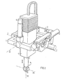
- FIG. 1 illustrates a universal or gimbal-ring type suspension comprising a mounting 2 which can be attached to a wall, a ceiling or some other bearing structure, and in which a "ring” 1 is mounted on journals for rctation about a first pivot axis I. Pivotally mounted in the “ring” 1 on journals or trunnions 5 and 6 (of which 4. The "ring” 1 is swung by a motor 3 and a lever system, merely outlined in the figure, which is activated by a spindle driven by the motor 3. Although not apparent from the figure, a similar swinging mechanism of this construction is able to swing the box-like structure about the axis II.
- Extending from the box-like structure is an arm 7 provided with a tool holder securing a tool 8.
- the arm 7 can be rotated about its longitudinal axis anc extended out of and withdrawn into the box-like structure L as indicated by the arrows shown, in a manner hereinafter cescribed.
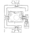
- Fig. 2 is a sectional view taken through the axes I anc II (with the gimbal-ring type suspension locatec centrally).
- the box-like structure 4 which is thus gimbal-ring type or universally suspended, has provided therein two mutually parallel guides 10 and 11, which extend almost the whole length of the box-like structure at right angles to the axes I and II and are attached to said structure from the inside thereof with the aid of adjustable attachment means 12 and 13.
- a platform 20 is slidably mounted on the guides. for translational movement, driven by the motor 9 (Fig. 1) via the journal means 5 rotatably mounted in both the "ring” 1 and the box-like structure 4.
- the principle of transmission through the trunnion or journal pin has been made the subject of Swedish Patent Application Serial No. .......... Seated on the inner end of the journal meqns is a pinion 22 which meshes with a rack attached to the platform 20 and extending parallel to the guides 10 and 11.
- the platform 20 arranged for movement in the box-like structure 4 can best be seen in Fig. 3.
- the two tearing carrying support plates 25 and 26 of the platform 20 are joined by a rigid structure.
- the arm 7 is rotated by means of a motor 28 whose outward shaft drives the gear 31 via an intermediate gear.
- the shaft to the intermediate gear is made adjustable, so that mating of the two gears can be adjusted to exclude any play.
- the two motors 29 and 30 are attached to the gear 27 and thus accompany the rotational movement of the gear, and therewith the arm 7, effected by the motor 28.
- the cables supplying the motors 28,29 and 30 together with other devices, such as compressed air hoses 32 serving the tool attachment and necessary to the action of the robot will consequently become tangled and twisted.
- the solution to the problem resulting herefrom has been mace the subject of a separate Swedish Patent Application Serial No. .
- Each of the motors 29 and 30 drives its respective shaft 33 and 34 which in turn respectively effect a swinging or rotational motion about an axis 35 which extends at right angles to the axial direction of the shaft 7 and about an axis 36 which extends at right angles to the shaft 35, whereby the actual tool holder obtains two further degrees of movement.
- the industrial robot is therewith equipped with six degrees of freedom and thus theoretically has full freedom of motion within its definition range.
- the working area had the form of a truncatea cone having a height of 350 mm, half the cone angle 30°, and the wider base part being of circular shape with a radius of 500 mm. Within this approximative working area there was achieved a setting accuracy in respect of the tool attachment of 0.1 mm cr better.
Abstract
Description
- The present invention relates to an industrial robot having a global-ring type suspended part which can be swung about two mutually perpendicular axes by means of a first and a second motor, there being arranged in the gimbal-ring type suspended part an arm which is driven for translatory motion by a third motor and which has a rotatable or twist- able tool attachment mountea on an outwardly projecting end thereof.
- An industrial robot of this kind is known from Japanese Patent Application No. 53-52776. The translatorily movable arm of this known construction comprises a screw-threaded spindle which is locked against rotation and which can be moved axially with the aid of an axially immovable nut capable of being turned by a motor.
- This construction, however, affords only three degrees of freedom in space, meaning that the tool attachment can be placed in any selected position in a working range. In order to cause, for example, a gripping tool to adopt an adjustable attitude there are, in principle, required three further degrees of freedom, which means that there must be mounted on the translatorily movable arm either three motors with associated movable members or at least the three members which move internally of one another that are required when the force shall be applied from motors positioned at some other location. Since the Japanese applica-"outermost" bearing of the gimbal-ring type or universal suspension, it is not seen how this further problem can be readily solved.

- The solution afforded by the universal or gimbal-ring type suspension is of principle interest, however, with respect to the possibilities of achieving rapid motion. This applies particularly to constructions which incorporate articulated arms and the like, since the fact that the drive motors must be placed adjacent to or preferably in a stationary mounting part presents a further problem.
- An object of the present invention is to provide a rapidly operating and accurate industrial robot constructed on the basis of the known gimbal-ring type suspension. In this respect the use of heavy motors and like devices shall not render the arrangement sluggish when mounted in tne proximity of the principal pivot points of the system. The invention is thus based on the view that, contrary to the proposals set forth in the aforesaid Japanese application, it is unnecessary to mount all motors on the stationary mounting of the robot, but that the motors shall instead be mounted in the vicinity of points at which the principal pivot or swinging axes intersect, therewith obviating, in accordance with the invention, the requirement that they shall be immovable.
- More specifically, these and other advantages together with further objects of the invention are achieved with an industrial robot of the kind mentioned in the introduction having the characteristic features set forth in the characterizing clause of Claim 1. The gimbal-ring type suspended part suitably has the form of a box-like structure or a tube of preferably rectangular cross-section, in which guide means are arranged. The platform, which thus carriesof the arrangement and the translational movement is characterized by its sluggish mass. The mobility and speed of remaining degrees of freecom, however, are not unduly influenced hereby and the industrial robot is distinguisheo by its high degree of mobility in operation and the high degree of operational control afforded.

- The fifth and the sixth motor each drives its respective shaft and is located at a constant distance from the tool attachment, and hence power can be transferred readily via rotational journal pins or trunnions with a minimum of play. The wrist joint located at the tool attachment may have the construction disclosed, for example, in a Swedish Patent Application Serial No ..........
- The invention will now be described with reference to an embodiment thereof illustrated in the drawings. In the drawings,
- Fig. 1 is a total view of an industrial robot.
- Fig. 2 is a sectional view of the robot illustratea in Fig. 1, with the section taken through the pivot axes of the gimbal-ring type suspension.
- Fig. is an exploded view of the translatorily movable platform with its rotatable arm and tool attachment.
- The schematic view of Fig. 1 illustrates a universal or gimbal-ring type suspension comprising a mounting 2 which can be attached to a wall, a ceiling or some other bearing structure, and in which a "ring" 1 is mounted on journals for rctation about a first pivot axis I. Pivotally mounted in the "ring" 1 on journals or
trunnions 5 and 6 (of which4. The "ring" 1 is swung by a motor 3 and a lever system, merely outlined in the figure, which is activated by a spindle driven by the motor 3. Although not apparent from the figure, a similar swinging mechanism of this construction is able to swing the box-like structure about the axis II.
- Extending from the box-like structure is an
arm 7 provided with a tool holder securing a tool 8. Thearm 7 can be rotated about its longitudinal axis anc extended out of and withdrawn into the box-like structure L as indicated by the arrows shown, in a manner hereinafter cescribed. - Fig. 2 is a sectional view taken through the axes I anc II (with the gimbal-ring type suspension locatec centrally). The box-like structure 4, which is thus gimbal-ring type or universally suspended, has provided therein two mutually
parallel guides 10 and 11, which extend almost the whole length of the box-like structure at right angles to the axes I and II and are attached to said structure from the inside thereof with the aid of adjustable attachment means 12 and 13. Aplatform 20 is slidably mounted on the guides. for translational movement, driven by the motor 9 (Fig. 1) via the journal means 5 rotatably mounted in both the "ring" 1 and the box-like structure 4. The principle of transmission through the trunnion or journal pin has been made the subject of Swedish Patent Application Serial No. .......... Seated on the inner end of the journal meqns is apinion 22 which meshes with a rack attached to theplatform 20 and extending parallel to theguides 10 and 11. - The
platform 20 arranged for movement in the box-like structure 4 can best be seen in Fig. 3. The two tearing carryingsupport plates 25 and 26 of theplatform 20 are joined by a rigid structure. the
the
gear 27. Thearm 7 is rotated by means of amotor 28 whose outward shaft drives the gear 31 via an intermediate gear. The shaft to the intermediate gear is made adjustable, so that mating of the two gears can be adjusted to exclude any play. The twomotors gear 27 and thus accompany the rotational movement of the gear, and therewith thearm 7, effected by themotor 28. The cables supplying themotors compressed air hoses 32 serving the tool attachment and necessary to the action of the robot will consequently become tangled and twisted. The solution to the problem resulting herefrom has been mace the subject of a separate Swedish Patent Application Serial No. ..... - Each of the
motors axis 35 which extends at right angles to the axial direction of theshaft 7 and about anaxis 36 which extends at right angles to theshaft 35, whereby the actual tool holder obtains two further degrees of movement. The industrial robot is therewith equipped with six degrees of freedom and thus theoretically has full freedom of motion within its definition range. - It will be noticed that all degrees of freedom, with the exception of one, are achieved by rotational or twisting motion about a horizontal or about a vertical axis, ana in the main through points which lie close to the centre of gravity of the rotated part and with the major part of the movable mass close to the axis of rotation, so that inertia forces are low. Only one degree of freedom is associatec with translatory motion whose inertia may have significance. Consequently, the tool holder can be subjected toAs an example in this respeet, a test plant having the following data was constructed.

- The working area had the form of a truncatea cone having a height of 350 mm, half the
cone angle 30°, and the wider base part being of circular shape with a radius of 500 mm. Within this approximative working area there was achieved a setting accuracy in respect of the tool attachment of 0.1 mm cr better.
Claims (3)
Applications Claiming Priority (2)
| Application Number | Priority Date | Filing Date | Title |
|---|---|---|---|
| SE8402693 | 1984-05-18 | ||
| SE8402693A SE453974B (en) | 1984-05-18 | 1984-05-18 | INDUSTRIAL ROBOT WITH TWO KARDANICALLY ORGANIZING TURNING SHAFT |
Publications (3)
| Publication Number | Publication Date |
|---|---|
| EP0180558A2 true EP0180558A2 (en) | 1986-05-07 |
| EP0180558A3 EP0180558A3 (en) | 1987-09-02 |
| EP0180558B1 EP0180558B1 (en) | 1989-09-13 |
Family
ID=20355937
Family Applications (1)
| Application Number | Title | Priority Date | Filing Date |
|---|---|---|---|
| EP85850154A Expired EP0180558B1 (en) | 1984-05-18 | 1985-05-02 | An industrial robot having two gimbal-ring type arranged swinging axes |
Country Status (5)
| Country | Link |
|---|---|
| US (1) | US4710092A (en) |
| EP (1) | EP0180558B1 (en) |
| JP (1) | JPS60255377A (en) |
| DE (1) | DE3572941D1 (en) |
| SE (1) | SE453974B (en) |
Cited By (2)
| Publication number | Priority date | Publication date | Assignee | Title |
|---|---|---|---|---|
| EP0472778A2 (en) * | 1990-08-28 | 1992-03-04 | Montech AG | Linear translation unit |
| EP1829651A1 (en) * | 2004-12-14 | 2007-09-05 | HONDA MOTOR CO., Ltd. | Joint structure for robot |
Families Citing this family (7)
| Publication number | Priority date | Publication date | Assignee | Title |
|---|---|---|---|---|
| JPS63185592A (en) * | 1987-01-28 | 1988-08-01 | 國洋電機工業株式会社 | Multi-sorting distributor for small article |
| US5102280A (en) * | 1989-03-07 | 1992-04-07 | Ade Corporation | Robot prealigner |
| JP4971984B2 (en) * | 2006-02-01 | 2012-07-11 | 本田技研工業株式会社 | Robot joint structure |
| DE202007002364U1 (en) * | 2007-02-14 | 2008-06-19 | Kuka Systems Gmbh | positioning |
| JP4754011B2 (en) * | 2009-06-16 | 2011-08-24 | 株式会社誠和工業 | Inclination angle setting device for stationary plate in vacuum suction pad setting device |
| EP2868434A1 (en) * | 2013-10-30 | 2015-05-06 | Barload Machine Co.,Ltd. | Front door-type automatic material-taking device |
| US9505126B2 (en) | 2014-10-27 | 2016-11-29 | Michele D'Egidio | Device for the movement and positioning of an element in space |
Citations (1)
| Publication number | Priority date | Publication date | Assignee | Title |
|---|---|---|---|---|
| US4115684A (en) * | 1976-06-17 | 1978-09-19 | Unimation | Portable, programmable manipulator apparatus |
Family Cites Families (8)
| Publication number | Priority date | Publication date | Assignee | Title |
|---|---|---|---|---|
| US3212649A (en) * | 1960-07-15 | 1965-10-19 | American Mach & Foundry | Machine for performing work |
| US3665148A (en) * | 1971-04-07 | 1972-05-23 | Gen Motors Corp | Six-axis manipulator |
| JPS5148616Y2 (en) * | 1971-10-01 | 1976-11-24 | ||
| US3948093A (en) * | 1975-06-30 | 1976-04-06 | International Business Machines Corporation | Six degree of freedom force transducer for a manipulator system |
| DE2647522A1 (en) * | 1976-10-21 | 1978-05-03 | Huels Chemische Werke Ag | TEXTILE AREA |
| JPS5518962A (en) * | 1978-07-27 | 1980-02-09 | Hitachi Ltd | Device for detecting in nuclear reactor vessel |
| JPS5676393A (en) * | 1979-11-19 | 1981-06-23 | Kawasaki Heavy Ind Ltd | Industrial robot device |
| JPS605432B2 (en) * | 1980-09-30 | 1985-02-12 | ファナック株式会社 | industrial robot |
-
1984
- 1984-05-18 SE SE8402693A patent/SE453974B/en not_active IP Right Cessation
-
1985
- 1985-05-02 DE DE8585850154T patent/DE3572941D1/en not_active Expired
- 1985-05-02 EP EP85850154A patent/EP0180558B1/en not_active Expired
- 1985-05-10 US US06/732,650 patent/US4710092A/en not_active Expired - Fee Related
- 1985-05-17 JP JP60105753A patent/JPS60255377A/en active Pending
Patent Citations (1)
| Publication number | Priority date | Publication date | Assignee | Title |
|---|---|---|---|---|
| US4115684A (en) * | 1976-06-17 | 1978-09-19 | Unimation | Portable, programmable manipulator apparatus |
Cited By (5)
| Publication number | Priority date | Publication date | Assignee | Title |
|---|---|---|---|---|
| EP0472778A2 (en) * | 1990-08-28 | 1992-03-04 | Montech AG | Linear translation unit |
| EP0472778A3 (en) * | 1990-08-28 | 1992-07-15 | Montech Ag | Linear translation unit |
| EP1829651A1 (en) * | 2004-12-14 | 2007-09-05 | HONDA MOTOR CO., Ltd. | Joint structure for robot |
| EP1829651A4 (en) * | 2004-12-14 | 2008-02-20 | Honda Motor Co Ltd | Joint structure for robot |
| US7938038B2 (en) | 2004-12-14 | 2011-05-10 | Honda Motor Co., Ltd. | Joint structure of robot |
Also Published As
| Publication number | Publication date |
|---|---|
| EP0180558B1 (en) | 1989-09-13 |
| SE8402693L (en) | 1985-11-19 |
| JPS60255377A (en) | 1985-12-17 |
| SE8402693D0 (en) | 1984-05-18 |
| DE3572941D1 (en) | 1989-10-19 |
| EP0180558A3 (en) | 1987-09-02 |
| SE453974B (en) | 1988-03-21 |
| US4710092A (en) | 1987-12-01 |
Similar Documents
| Publication | Publication Date | Title |
|---|---|---|
| EP0080325B1 (en) | Split-ball type wrist and manipulator assembly for robot | |
| US4736645A (en) | Gear unit for a manipulator | |
| CN109476020B (en) | Gear assembly for robot joint | |
| US4062455A (en) | Remote manipulator | |
| US5811951A (en) | High precision redundant robotic manipulator | |
| US4402234A (en) | Three-axis wrist mechanism | |
| CA1256508A (en) | Industrial robot for welding and cutting by means of a laser beam | |
| EP0066393B1 (en) | Multiarm robot | |
| US7478576B2 (en) | Robotic manipulator | |
| US7849761B2 (en) | Wrist unit to a robot arm | |
| GB2083795A (en) | Manipulator mechanisms | |
| JPH0776797B2 (en) | Remotely operable positioning and supporting device for remote processing equipment | |
| WO1993020982A1 (en) | Six degree of freedom motion device | |
| EP0180558A2 (en) | An industrial robot having two gimbal-ring type arranged swinging axes | |
| JPH05301194A (en) | Cable processing device of industrial robot | |
| JPH01150042A (en) | Manipulator joint mechanism | |
| US11938624B2 (en) | Parallel kinematic robot | |
| JP2585425B2 (en) | Vertical articulated robot | |
| JPS61168487A (en) | Mechanical wrist mechanism | |
| GB1568248A (en) | Manipulator arm including a drive unit | |
| JP2710585B2 (en) | Industrial manipulator | |
| EP0174916A2 (en) | An arrangement in an industrial robot | |
| GB2116142A (en) | Wrist mechanisms for manipulator apparatus | |
| JPH03202287A (en) | Industrial robot | |
| JPS6279991A (en) | Multidegree-of-freedom arm type inspection device |
Legal Events
| Date | Code | Title | Description |
|---|---|---|---|
| PUAI | Public reference made under article 153(3) epc to a published international application that has entered the european phase |
Free format text: ORIGINAL CODE: 0009012 |
|
| AK | Designated contracting states |
Kind code of ref document: A2 Designated state(s): DE FR GB IT |
|
| PUAL | Search report despatched |
Free format text: ORIGINAL CODE: 0009013 |
|
| AK | Designated contracting states |
Kind code of ref document: A3 Designated state(s): DE FR GB IT |
|
| 17P | Request for examination filed |
Effective date: 19871104 |
|
| 17Q | First examination report despatched |
Effective date: 19890102 |
|
| GRAA | (expected) grant |
Free format text: ORIGINAL CODE: 0009210 |
|
| AK | Designated contracting states |
Kind code of ref document: B1 Designated state(s): DE FR GB IT |
|
| ITF | It: translation for a ep patent filed |
Owner name: JACOBACCI & PERANI S.P.A. |
|
| REF | Corresponds to: |
Ref document number: 3572941 Country of ref document: DE Date of ref document: 19891019 |
|
| ET | Fr: translation filed | ||
| PLBE | No opposition filed within time limit |
Free format text: ORIGINAL CODE: 0009261 |
|
| STAA | Information on the status of an ep patent application or granted ep patent |
Free format text: STATUS: NO OPPOSITION FILED WITHIN TIME LIMIT |
|
| 26N | No opposition filed | ||
| ITTA | It: last paid annual fee | ||
| PGFP | Annual fee paid to national office [announced via postgrant information from national office to epo] |
Ref country code: GB Payment date: 19930420 Year of fee payment: 9 |
|
| PGFP | Annual fee paid to national office [announced via postgrant information from national office to epo] |
Ref country code: FR Payment date: 19930510 Year of fee payment: 9 |
|
| PGFP | Annual fee paid to national office [announced via postgrant information from national office to epo] |
Ref country code: DE Payment date: 19930524 Year of fee payment: 9 |
|
| PG25 | Lapsed in a contracting state [announced via postgrant information from national office to epo] |
Ref country code: GB Effective date: 19940502 |
|
| GBPC | Gb: european patent ceased through non-payment of renewal fee |
Effective date: 19940502 |
|
| PG25 | Lapsed in a contracting state [announced via postgrant information from national office to epo] |
Ref country code: FR Effective date: 19950131 |
|
| PG25 | Lapsed in a contracting state [announced via postgrant information from national office to epo] |
Ref country code: DE Effective date: 19950201 |
|
| REG | Reference to a national code |
Ref country code: FR Ref legal event code: ST |