EP0182458A2 - Method and apparatus for time axis control - Google Patents
Method and apparatus for time axis control Download PDFInfo
- Publication number
- EP0182458A2 EP0182458A2 EP85305920A EP85305920A EP0182458A2 EP 0182458 A2 EP0182458 A2 EP 0182458A2 EP 85305920 A EP85305920 A EP 85305920A EP 85305920 A EP85305920 A EP 85305920A EP 0182458 A2 EP0182458 A2 EP 0182458A2
- Authority
- EP
- European Patent Office
- Prior art keywords
- time axis
- axis adjustment
- fine
- resetting
- circuit
- Prior art date
- Legal status (The legal status is an assumption and is not a legal conclusion. Google has not performed a legal analysis and makes no representation as to the accuracy of the status listed.)
- Granted
Links
Images

Classifications
-
- G—PHYSICS
- G11—INFORMATION STORAGE
- G11B—INFORMATION STORAGE BASED ON RELATIVE MOVEMENT BETWEEN RECORD CARRIER AND TRANSDUCER
- G11B20/00—Signal processing not specific to the method of recording or reproducing; Circuits therefor
- G11B20/02—Analogue recording or reproducing
- G11B20/025—Error detection or correction
-
- G—PHYSICS
- G11—INFORMATION STORAGE
- G11B—INFORMATION STORAGE BASED ON RELATIVE MOVEMENT BETWEEN RECORD CARRIER AND TRANSDUCER
- G11B27/00—Editing; Indexing; Addressing; Timing or synchronising; Monitoring; Measuring tape travel
- G11B27/10—Indexing; Addressing; Timing or synchronising; Measuring tape travel
-
- H—ELECTRICITY
- H04—ELECTRIC COMMUNICATION TECHNIQUE
- H04N—PICTORIAL COMMUNICATION, e.g. TELEVISION
- H04N5/00—Details of television systems
- H04N5/76—Television signal recording
- H04N5/91—Television signal processing therefor
- H04N5/93—Regeneration of the television signal or of selected parts thereof
- H04N5/95—Time-base error compensation
- H04N5/953—Time-base error compensation by using an analogue memory, e.g. a CCD shift register, the delay of which is controlled by a voltage controlled oscillator
-
- Y—GENERAL TAGGING OF NEW TECHNOLOGICAL DEVELOPMENTS; GENERAL TAGGING OF CROSS-SECTIONAL TECHNOLOGIES SPANNING OVER SEVERAL SECTIONS OF THE IPC; TECHNICAL SUBJECTS COVERED BY FORMER USPC CROSS-REFERENCE ART COLLECTIONS [XRACs] AND DIGESTS
- Y10—TECHNICAL SUBJECTS COVERED BY FORMER USPC
- Y10S—TECHNICAL SUBJECTS COVERED BY FORMER USPC CROSS-REFERENCE ART COLLECTIONS [XRACs] AND DIGESTS
- Y10S358/00—Facsimile and static presentation processing
- Y10S358/907—Track skippers, i.e. "groove skippers"
Landscapes
- Engineering & Computer Science (AREA)
- Signal Processing (AREA)
- Multimedia (AREA)
- Moving Of The Head For Recording And Reproducing By Optical Means (AREA)
- Signal Processing Not Specific To The Method Of Recording And Reproducing (AREA)
Abstract
Description
- The present invention relates to a method of time axis control which is used during recording or playback of data such as video signals or audio signals on or from a medium such as a disk or magnetic tape.
- In, for example a method of time axis control of a video disk player, a signal which is produced by a signal recording/playback unit including a pick-up is transferred through a CCD (charge coupled device) which forms a variable delay line and serves as a fine time axis adjustment unit. Part of the resultant output signal from the CCD is supplied to a circuit which performs sync separation and removal of equalizing pulses thereby to produce pulses which are synchronized with the playback horizontal sync signal. These pulses are input to a phase comparator and are compared in phase therein with an input signal from a reference frequency oscillator. The output signal from this oscillator has the same frequency as the playback horizontal sync signal (i.e., 15.734 KHz in the case of the NTSC system and 15.625 KHz in the case of the PAL system). The phase error output signal which is output from the phase comparator is transferred to a motor driving the disk. In addition, the output signal is applied to a VCO (voltage-controlled oscillator) to control clock pulses which are applied to the CCD. In this way, coarse time axis control is performed by a changing the speed of the disk drive motor and fine time axis control is performed by the CCD.
- During a skip-scanning operation, in which the pick-up is alternately and successively set in a track jumping mode of operation whereby one or more tracks are skipped over, and a tracking servo mode operation, in which the pick-up is made to follow along a track while time axis control is continued, playback of the video signal takes place during each of the intervals in which tracking occurs. Corresponding images appear upon a monitor. Thus, such a skip-scan operation is analagous to looking up pages in a book.
- In the case of a CAV (constant angular velocity) disk in which the positions at which the horizontal and vertical sync signals are recorded are positioned along radial lines on the disk, no problems arise with such scanning. However, in the case of a CLV (constant linear velocity) or CAV (constant angular velocity) disk, the positions at which the horizontal and vertical sync signals are recorded do not lie along a disk radius so that discontinuities arise between the signal phase prior to a track jumping operation and the phase subsequent to that operation. Thus, each time a track jump operation takes place, a large-amplitude error signal is produced by the time axis servo system of the disk player, and hence a relatively long time is required before stable operation is restored. In addition, there is a danger that erroneous operation may result due to the maximum compensation range of the CCD being exceeded. For this reason, when a comparatively large-amplitude time axis error is produced, the fine time axis adjustment unit constituted by the CCD loop is placed in the off state, and only the coarse time axis adjustment unit (i.e., the spindle motor servo loop) is set in operation. As a result, colour sync is lost from the displayed monitor picture, causing a black-and-white image to be displayed. A further disadvantage of this method is that, when the scanning operation is terminated and normal playing is restarted, a relatively long time must elapse before time axis control can be stabilized, that is, to reduce the time axis error to a sufficiently low value. During that time, an objectionable colouration state appears on the monitor display.
- A proposed method of overcoming the problems described above is disclosed in Japanese Patent No. 58-98881. With that method, during a track jump operation, a hold condition is established for a frequency divider used as a counter. The hold state is implemented by a gate pulse which occurs during the interval in which a track jump operation takes place. In this way, it is proposed to ensure smooth continuity for the time axis error without disturbances occurring in the value of the error.
- However, in fact, even when the technique described in the above-mentioned patent is employed, colour disturbances still appear on the displayed monitor image due to disturbances of the time axis data while scanning operations are repetitively performed. This is due to the fact that, during the scanning operation, when the limit of the range of movement of the tracking mirror (which forms part of the signal recording/playback unit) is approached, a "tracking servo loop open" pulse is generated, which causes the mirror to be restored to a position close to the center of its range of movement. These "tracking servo loop open" pulses are generated in a manner which is unrelated to the period of the time axis error. Thus, when scanning operations are repetitively performed, problems will arise.
- Firstly, although the time axis error is applied in a smoothly continuous fashion, the process of correction of the time axis error (commencing after each track jump operation when the CCD is reconnected) begins from the condition existing immediately prior to that track jump, i.e., from a condition in which a certain amount of offset is contained in the error quantity.
- Another problem is that the distance between the center position of a track jump and the positions at which the jump begins and ends (measured radially along the disk surface) corresponds to a substantial number of tracks. Thus, in the case of a CLV disk, the speed of rotation of the spindle motor should change by an amount which corresponds to that radial position difference. However due to the slow speed of response of the spindle motor, it is necessary for this compensation to be performed by the CCD, which has a high speed of response. When such track jump operations are performed repetitively, the offset value (the operating point deviation) tends to accumulate and gradually increase. If this can be compensated by appropriate rotation of the spindle motor, then no problem arises. However, if a large amount of offset is generated within a short time interval, then the spindle motor is not able to respond with sufficient rapidity, and eventually the limit of compensation by the CCD is reached. Loss of display colour and time axis disturbances then result.
- According to this invention a method of time axis control during recording on or reproduction from a recording medium in which coarse time axis adjustment and fine time axis adjustment are performed in accordance with the relative speeds of the recording medium and signal recording/playback means including a tracking control operation wherein the signal recording/playback means follows a track formed on the recording medium and performs repetitive track jumping operations over successive tracks by moving the signal recording/playback means is characterised in that during each track jumping operation, time constant means, within at least a circuit which performs the fine time axis adjustment, is reset.
- With the method in accordance with this invention it is possible to display a colour image even when scanning is implemented for CAV or CLV disks, and the displayed images are natural in appearance.
- The fine time axis adjustment may be carried out using CCD in which case the step of resetting the time constant is done by discharging a time constant circuit contained within the time axis control system, which includes the CCD. Moreover, when the fine time axis adjustment is performed by controlling the position of the signal recording/playback means, the resetting of the time constant means restores recording/playback means to its centre position.
- Particular examples of methods and apparatus in accordance with this invention will now be described and contrasted with the prior art with reference to the accompanying drawings, in which:-
- Figure 1 is a block diagram of a prior apparatus;
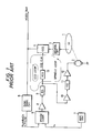
- Figure 2 is a block diagram of a time axis control device of the present invention;
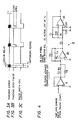
- Figures 3A to 3C are waveform diagrams for describing the operation of the invention;
- Figure 4 is a circuit diagram of an equalizer used in the device shown in Figure 2;
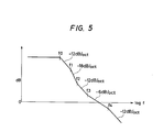
- Figure 5 shows the frequency characteristic of the circuit of Figure 4; and,
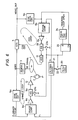
- Figure 6 is a block diagram of another time axis control device of the invention.
- Figure 1 shows an example of a conventional device for time axis control of a video disk player.
Reference numeral 1 denotes a video disk, and reference numeral 2 a spindle motor which rotates thevideo disk 1. A signal which is produced by a signal recording/playback unit including a pick-up (not shown in the drawings) is demodulated by ademodulator circuit 3, and the demodulated signal thus produced is transferred through a CCD (charge coupled device) 4 which serves as fine time axis adjustment unit. Part of the resultant output signal from theCCD 4 is supplied to a circuit 5 which performs sync separation and removal of equalizing pulses to thereby produce pulses which are synchronized with the playback horizontal sync signal. These pulses are input to aphase comparator 6 and are compared in phase therein with an input signal from areference frequency oscillator 7. The output signal from this oscillator has the same frequency as the playback horizontal sync signal (i.e., 15.734 KHz in the case of the NTSC system and 15.625 KHz in the case of the PAL system). The phase error output signal which is output from thephase comparator 6 is transferred through anamplifier 8,equalizer 9,amplifier 10,equalizer 11 andamplifier 12 to themotor 2. In addition, the output signal from theequalizer 9 is applied to a VCO (voltage-controlled oscillator) 13 to control the clock pulses which are applied to the CCD. In this way, coarse time axis control is performed by a loop including thedemodulator circuit 3,CCD 4, sync separator circuit 5,phase comparator 6,amplifier 8,equalizer 9,amplifier 10,equalizer 11,amplifier 12 andmotor 2. On the other hand, fine time axis control is performed by a loop comprising sync separator circuit 5,phase comparator 6,amplifier 8,equalizer 9,VCO 13 andCCD 4. - During a skip-scanning operation, in which the pick-up is alternately and successively set in a track jumping mode of operation whereby one or more tracks are skipped over, and a tracking servo mode of operation, in which the pick-up is made to follow along a track while time axis control is continued, playback of the video signal takes place during each of the intervals in which tracking occurs. Corresponding images appear upon the monitor.
- Figure 2 shows a time axis control device operation in accordance with the inventive method. Those components which correspond to components in the prior art example of Figure 1 are indicated by corresponding reference numerals, and further description of these will be omitted hereinafter.
- With the arrangement of Figure 2, an
oscillator 20, producing a reference frequency signal whose frequency is N times that of the horizontal sync signal, and afrequency divider 21, which frequency divides the latter output signal by afactor 1/N, constitute in combination a circuit for supplying reference frequency horizontal sync pulses to thephase comparator 6.Reference numerals pulse extension circuit 24 and a D-type flip-flop 25. - The operation of this circuit will now be described. The method of time axis control by a fine time axis adjustment system based on the
CCD 4 and the coarse time axis adjustment system based on thespindle motor 2 are identical to those of Fig. 1, and therefore only the points of difference from the example of Fig. 1 will be described in the following. - The signal which is input to the
pulse extension circuit 24 consists of pulses which act to set the tracking servo loop in the open state when the tracking mirror reaches a limit position of its range of movement during servo operation (Fig. 3B). Thepulse extension circuit 24 receives these pulses as in input and produces pulses of longer width as an output (Fig. 3C). When one of these "tracking servo loop open" pulses terminates, the tracking servo loop returns to the closed state. However, although switching then occurs to restore the operating condition in which the pick-up follows a disk track, the tracking servo loop will not attain a stable operating status immediately. This is due to reasons such as inertia. - The width of the pulses which are output from the
pulse extension circuit 24 is determined on the basis of the time required for the system to reach a stable condition. Thus, at the time of termination of an output pulse from thepulse extension circuit 24, the tracking servo loop will have attained the locked-in status, and the tracking error will have been reduced to a sufficiently low value. - The extended-width pulses thus produced are input to the data terminal D of D-type flip-
flop 25, while the playback horizontal sync pulses derived by the sync separator circuit 5 are applied to the clock terminal CK. The output signal from the D-type flip-flop 25 therefore consists of pulses each having a leading edge which occurs when the first horizontal sync pulse is applied following the initiation of generating an extended-width pulse and having a trailing edge which occurs when the first horizontal sync pulse is applied following the termination of the extended-width pulse. In this way, extended-width pulses are output from the D-type flip-flop 25 which are synchronized with the playback horizontal sync signal. - While a pulse is thus being output from D-type flip-
flop 25, theswitch 22 is held in the open state and theswitch 23 in the closed state. When theswitch 22 is opened, application of pulses from theoscillator 20 to the counter circuit constituted by thefrequency divider 21 is interrupted and the current count state therein is thus held. In this way, the reference frequency horizontal sync pulses cease to be output from thefrequency divider 21 during such a hold interval so that the reference frequency horizontal sync pulses cease to be input to thephase comparator 6. The output from thephase comparator 6 thereby moves in a direction such as to cause the speed of rotation of thespindle motor 2 to decrease. The closing of theswitch 23 acts to discharge the time constant circuit in theequalizer 9 so that the output from theequalizer 9 becomes identical to that which would be produced during normal servo operation if the time axis error were zero. As a result, thespindle motor 2 andCCD 4 operate in the same manner as when the error signal is zero. - Upon termination of the pulse output from the D-type flip-
flop 25, theswitch 22 returns to the closed state. The time required to complete a track jump operation is comparatively short, and themotor 2 cannot respond with sufficient rapidity during this short time interval due to the comparatively large inertia of the motor. Thus, the speed of rotation of thespindle motor 2 immediately after a track jump operation has terminated will be almost unchanged from the speed immediately prior to the jump operation in many cases. For this reason, the phase relationship between the reference frequency horizontal sync pulses and the playback horizontal sync pulses immediately prior to a track jump operation is held as a count value, and counting is recommenced immediately after the jump operation is terminated, in synchronism with the playback horizontal sync pulses. This has the same effect as setting the phase relationship between the reference frequency horizontal sync pulses and the playback horizontal sync pulses to the same value as that existing prior to the track jump operation. In this way, continuity of the time axis error is maintained. - Up until a point in time immediately preceding a track jump operation, the time axis servo loop is held closed, and the phase error signal output from the
phase comparator 6 will have a value close to zero. Setting the phase relationship between the reference frequency horizontal sync pulses and the playback horizontal sync pulses following termination of a track jump operation to the relationship immediately prior to the jump is performed by halting counting by the 1/N counter 21, and setting or presetting the value of output from thecounter 21 to be zero or close to zero as a target value for the time axis servo loop, with this setting being carried out at a point following the start of the jump operation. Thus, immediately following termination of the track jump, counting by thecounter 21 is restarted from a value which represents a phase difference close to zero, with counting being performed in synchronism with the playback horizontal sync pulses. - With such a method, even if drop-out occurs just before a track jump operation and an abnormal phase error signal is produced, this abnormal value will not result in any delay in operation of the servo system immediately after the track jump operation. In this way, the value which has been set into the 1/
N counter 21 ensures that the phase difference between the playback horizontal sync pulses and the reference frequency horizontal sync pulses will always be close to zero immediately following a track jump operation. - As a result of termination of the output pulse from the D-type flip-
flop 25, whereby theswitch 23 is opened, theCCD 4 again commences to perform fine time axis adjustment based on the operating center point. Thus, no accumulation of offset (i.e., operating point deviation) will occur as a result of repetitive track jump operations being carried out. In addition, a normal time axis error signal is applied to themotor 2 as a compensation signal so that a clear color image will appear on the monitor during the track jumping operation. - Fig. 4 shows an embodiment of the
equalizer 9 shown in Fig. 2. This circuit includes an active low-pass filter 27, having a cut-off frequency fa, composed of capacitors Cl and C2, resistors R1 and R2, and anoperational amplifier 26; a low-frequency range gain-boost equalizer 29 composed of resistors R3 and R4, capacitor C2, and anoperational amplifier 28; and a phaseadvance compensation circuit 30 made up of resistors R5 and R6 and capacitor C4. - The overall gain characteristic of this circuit is shown in Fig. 5. The frequencies indicated in Fig. 5 are derived as follows:


- When the CCD loop contains a plurality of time constant circuits as in this embodiment, then all of these can be discharged. However it is more efficient, and equally effective, to discharge only the time constant circuit which has the highest time constant value. In this embodiment, therefore, switches 23a and 23b are connected such as to short-circuit the terminals of capacitors C1 and C2, respectively.
- In the embodiment of Fig. 2, the sync separator circuit 5,
phase comparator 6,amplifier 8 andequalizer 9 are used in common by both the fine adjustment loop (i.e., the CCD loop) and the coarse adjustment loop (i.e., the spindle motor loop). However in the case of the embodiment shown in Fig. 6, these two loops are kept mutually independent by providingsync separator circuits phase comparators amplifiers equalizers 9a and 9b. It will be apparent that such an arrangement too is in accordance with the present invention. It should be noted that if theswitch 23, provided for theequalizer 9a, is omitted, no problems will arise in actual operation. - Since the
spindle motor 2 will generally have a comparatively large amount of inertia, it cannot respond very rapidly. Thus, if the time required to complete a track jump operation is very short, then even if no reference frequency horizontal sync pulses are output from the frequency divider (counter) 21 during the jump interval, virtually no change in the speed of rotation of themotor 2 will occur during that interval. - In the above embodiments, a CCD is employed in the fine time axis adjustment unit. However it is equally possible to employ an actuator having, for example, a tangential mirror. In this case, the actuator itself will have the highest time constant value within the loop. Since it will not be possible to perform discharging as is done in the case of an electrical time constant circuit, it will be necessary to employ some other method of resetting the fine time axis adjustment unit. This can take the form of, for example, allowing current to flow into the actuator only while the actuator has returned to its central position (the neutral position), or performing detection of the angular displacement of the actuator and passing a current through the actuator in such a direction as to pull it forcibly back to the central position of its range of angular displacement.
- As described hereinabove, with the present invention, resetting of the fine time axis adjustment unit is performed when the tracking servo loop is opened during a scanning operation. This ensures that a color image is displayed even when such scanning is implemented for CAV or CLV disks. In addition, the displayed image is natural in appearance and easy to view.
Claims (9)
Applications Claiming Priority (2)
| Application Number | Priority Date | Filing Date | Title |
|---|---|---|---|
| JP173716/84 | 1984-08-21 | ||
| JP59173716A JPS6151673A (en) | 1984-08-21 | 1984-08-21 | Time base control system |
Publications (3)
| Publication Number | Publication Date |
|---|---|
| EP0182458A2 true EP0182458A2 (en) | 1986-05-28 |
| EP0182458A3 EP0182458A3 (en) | 1987-09-30 |
| EP0182458B1 EP0182458B1 (en) | 1990-11-22 |
Family
ID=15965809
Family Applications (1)
| Application Number | Title | Priority Date | Filing Date |
|---|---|---|---|
| EP85305920A Expired EP0182458B1 (en) | 1984-08-21 | 1985-08-20 | Method and apparatus for time axis control |
Country Status (4)
| Country | Link |
|---|---|
| US (1) | US4763205A (en) |
| EP (1) | EP0182458B1 (en) |
| JP (1) | JPS6151673A (en) |
| DE (1) | DE3580653D1 (en) |
Cited By (2)
| Publication number | Priority date | Publication date | Assignee | Title |
|---|---|---|---|---|
| EP0282242A2 (en) * | 1987-03-09 | 1988-09-14 | Pioneer Electronic Corporation | A phase synchronizing circuit for a time axis shift correcting circuit |
| EP0394919A2 (en) * | 1989-04-25 | 1990-10-31 | Sony Corporation | A video disc player |
Families Citing this family (9)
| Publication number | Priority date | Publication date | Assignee | Title |
|---|---|---|---|---|
| KR910005644B1 (en) * | 1986-09-19 | 1991-08-01 | 가부시키가이샤 도시바 | Disk recording/reproducing apparatus |
| US4862291A (en) * | 1986-11-14 | 1989-08-29 | Pioneer Electronic Corporation | Scanning system in information reproducing apparatus |
| US5220736A (en) * | 1987-03-19 | 1993-06-22 | Canon Kabushiki Kaisha | Reproducing apparatus with time base corrector |
| JPH0268764A (en) * | 1988-09-02 | 1990-03-08 | Pioneer Electron Corp | Multiple speed reproducing controller for video disk player |
| US4947093A (en) * | 1988-11-25 | 1990-08-07 | Micropolis Corporation | Shock resistant winchester disk drive |
| JP2751363B2 (en) * | 1989-04-13 | 1998-05-18 | ソニー株式会社 | Video disc player |
| KR920003426B1 (en) * | 1989-10-13 | 1992-04-30 | 삼성전자 주식회사 | Over-rotation stop device of spindle motor |
| KR930003193B1 (en) * | 1991-01-25 | 1993-04-23 | 삼성전자주식회사 | Unusual circulation preventing circuit of spindle motor |
| JP2014160523A (en) * | 2013-02-20 | 2014-09-04 | Funai Electric Co Ltd | Optical disk device and equalizer adjustment method |
Citations (6)
| Publication number | Priority date | Publication date | Assignee | Title |
|---|---|---|---|---|
| JPS5753188A (en) * | 1980-09-17 | 1982-03-30 | Olympus Optical Co Ltd | Jitter correct circuit of optical disc reader |
| US4345279A (en) * | 1979-10-16 | 1982-08-17 | Olympus Optical Co., Ltd. | Time base correction apparatus |
| JPS5864647A (en) * | 1981-10-13 | 1983-04-18 | Pioneer Video Corp | Controller for track tangential relative position between recording track and pickup of information reader |
| JPS58179965A (en) * | 1982-04-14 | 1983-10-21 | Hitachi Ltd | Compensating circuit of fluctuation of time axis |
| US4422104A (en) * | 1980-04-23 | 1983-12-20 | Hitachi, Ltd. | Time base error correcting apparatus for video player |
| JPS595788A (en) * | 1982-07-01 | 1984-01-12 | Pioneer Video Kk | Reproducing horizontal synchronizing signal generator |
Family Cites Families (12)
| Publication number | Priority date | Publication date | Assignee | Title |
|---|---|---|---|---|
| US3959815A (en) * | 1974-01-28 | 1976-05-25 | Basf Aktiengesellschaft | Arrangements for time base error compensation |
| GB1572346A (en) * | 1976-03-19 | 1980-07-30 | Rca Corp | Velocity and phase control for a disc recording and reproducing apparatus |
| US4228460A (en) * | 1978-01-12 | 1980-10-14 | Basf Aktiengesellschaft | Method and apparatus for compensation of time base errors |
| US4358796A (en) * | 1978-03-27 | 1982-11-09 | Discovision Associates | Spindle servo system for videodisc player |
| JPS5599889A (en) * | 1979-01-05 | 1980-07-30 | Pioneer Video Corp | Tracking control unit in information reader |
| US4286282A (en) * | 1979-08-20 | 1981-08-25 | Rca Corporation | Periodically biased video disc player servo system |
| JPS56102182A (en) * | 1980-01-18 | 1981-08-15 | Pioneer Video Corp | Time axis correction device for video regenerative signal |
| JPS56163374U (en) * | 1980-05-06 | 1981-12-04 | ||
| JPS5764371A (en) * | 1980-09-30 | 1982-04-19 | Toshiba Corp | Rotation control system of disk recording medium |
| JPS5890879A (en) * | 1981-11-24 | 1983-05-30 | Matsushita Electric Ind Co Ltd | Time axis compensating device |
| JPS5898881A (en) * | 1981-12-08 | 1983-06-11 | Pioneer Video Corp | Time base controller for reproducing device of information recording disc |
| JPS5990262A (en) * | 1982-11-15 | 1984-05-24 | Nippon Gakki Seizo Kk | Reproducing device for disk |
-
1984
- 1984-08-21 JP JP59173716A patent/JPS6151673A/en active Granted
-
1985
- 1985-08-20 DE DE8585305920T patent/DE3580653D1/en not_active Expired - Fee Related
- 1985-08-20 US US06/767,450 patent/US4763205A/en not_active Expired - Lifetime
- 1985-08-20 EP EP85305920A patent/EP0182458B1/en not_active Expired
Patent Citations (6)
| Publication number | Priority date | Publication date | Assignee | Title |
|---|---|---|---|---|
| US4345279A (en) * | 1979-10-16 | 1982-08-17 | Olympus Optical Co., Ltd. | Time base correction apparatus |
| US4422104A (en) * | 1980-04-23 | 1983-12-20 | Hitachi, Ltd. | Time base error correcting apparatus for video player |
| JPS5753188A (en) * | 1980-09-17 | 1982-03-30 | Olympus Optical Co Ltd | Jitter correct circuit of optical disc reader |
| JPS5864647A (en) * | 1981-10-13 | 1983-04-18 | Pioneer Video Corp | Controller for track tangential relative position between recording track and pickup of information reader |
| JPS58179965A (en) * | 1982-04-14 | 1983-10-21 | Hitachi Ltd | Compensating circuit of fluctuation of time axis |
| JPS595788A (en) * | 1982-07-01 | 1984-01-12 | Pioneer Video Kk | Reproducing horizontal synchronizing signal generator |
Non-Patent Citations (5)
| Title |
|---|
| PATENT ABSTRACTS OF JAPAN, vol. 6, no. 128 (E-118)[1006], 14th July 1982; & JP-A-57 053 188 (OLYMPUS KOGAKU KOGYO K.K.) 30-03-1982 * |
| PATENT ABSTRACTS OF JAPAN, vol. 7, no. 156 (P-209)[1301], 8th July 1983; & JP-A-58 064 647 (YUNIBAASARU PAIONIA K.K.) 18-04-1983 * |
| PATENT ABSTRACTS OF JAPAN, vol. 8, no. 23 (P-251)[1460], 31st January 1984; & JP-A-58 179 965 (HITACHI SEISAKUSHO K.K.) 21-10-1983 * |
| PATENT ABSTRACTS OF JAPAN, vol. 8, no. 84 (E-239)[1521], 18th April 1984; & JP-A-59 005 788 (PAIONIA BIDEO K.K.) 12-01-1984 * |
| RCA REVIEW, vol. 39, no. 1, March 1978, pages 198-221, Princeton, US; R.N. RHODES: "The videodisc player" * |
Cited By (4)
| Publication number | Priority date | Publication date | Assignee | Title |
|---|---|---|---|---|
| EP0282242A2 (en) * | 1987-03-09 | 1988-09-14 | Pioneer Electronic Corporation | A phase synchronizing circuit for a time axis shift correcting circuit |
| EP0282242A3 (en) * | 1987-03-09 | 1989-11-29 | Pioneer Electronic Corporation | A phase synchronizing circuit for a time axis shift correcting circuit |
| EP0394919A2 (en) * | 1989-04-25 | 1990-10-31 | Sony Corporation | A video disc player |
| EP0394919A3 (en) * | 1989-04-25 | 1992-11-25 | Sony Corporation | A video disc player |
Also Published As
| Publication number | Publication date |
|---|---|
| EP0182458A3 (en) | 1987-09-30 |
| JPH0157428B2 (en) | 1989-12-05 |
| EP0182458B1 (en) | 1990-11-22 |
| US4763205A (en) | 1988-08-09 |
| JPS6151673A (en) | 1986-03-14 |
| DE3580653D1 (en) | 1991-01-03 |
Similar Documents
| Publication | Publication Date | Title |
|---|---|---|
| EP0182458B1 (en) | Method and apparatus for time axis control | |
| NL8203308A (en) | DEVICE FOR REPRODUCTING REGISTERED DATA. | |
| EP0050024A2 (en) | Tracking-error correcting system in video reproducing apparatus | |
| US4322757A (en) | Servo control apparatus for adjusting the phase of a rotary head assembly to correct for errors which may occur due to changes in operating characteristics, while minimizing phase errors during edit operations | |
| EP0407970A2 (en) | Digital video signal reproducing apparatus | |
| US4215362A (en) | Track selection method and apparatus | |
| US4318142A (en) | Automatically compensated movable head servo circuit and method | |
| US4695778A (en) | Rotation phase control device | |
| US4494153A (en) | Method of operating a signal reproduction apparatus for effecting synchronous reproduction of recorded signals | |
| JPH0731872B2 (en) | Time axis control system | |
| EP0116926B1 (en) | Magnetic recording and reproducing apparatus | |
| JPS6036949Y2 (en) | video tape recorder | |
| US5065385A (en) | Time base control system with coarse and fine correction for a spindle servo | |
| JPH0434768A (en) | Clock extraction circuit | |
| JPH0519204B2 (en) | ||
| EP0282242B1 (en) | A phase synchronizing circuit for a time axis shift correcting circuit | |
| JPS6214900B2 (en) | ||
| JPH0520810A (en) | Time-axis control system | |
| EP0357352B1 (en) | Video signal recording/reproducing apparatus | |
| JP2506914B2 (en) | Digital servo device | |
| KR920002326Y1 (en) | For vtr auto tracking device | |
| JP2606371B2 (en) | Magnetic recording / reproducing device | |
| JP2502616B2 (en) | Servo device | |
| JP2506915B2 (en) | Digital servo device | |
| JPS634256B2 (en) |
Legal Events
| Date | Code | Title | Description |
|---|---|---|---|
| PUAI | Public reference made under article 153(3) epc to a published international application that has entered the european phase |
Free format text: ORIGINAL CODE: 0009012 |
|
| AK | Designated contracting states |
Kind code of ref document: A2 Designated state(s): DE GB NL |
|
| PUAL | Search report despatched |
Free format text: ORIGINAL CODE: 0009013 |
|
| AK | Designated contracting states |
Kind code of ref document: A3 Designated state(s): DE GB NL |
|
| 17P | Request for examination filed |
Effective date: 19880329 |
|
| 17Q | First examination report despatched |
Effective date: 19891004 |
|
| GRAA | (expected) grant |
Free format text: ORIGINAL CODE: 0009210 |
|
| AK | Designated contracting states |
Kind code of ref document: B1 Designated state(s): DE GB NL |
|
| REF | Corresponds to: |
Ref document number: 3580653 Country of ref document: DE Date of ref document: 19910103 |
|
| REG | Reference to a national code |
Ref country code: GB Ref legal event code: 746 |
|
| PLBE | No opposition filed within time limit |
Free format text: ORIGINAL CODE: 0009261 |
|
| STAA | Information on the status of an ep patent application or granted ep patent |
Free format text: STATUS: NO OPPOSITION FILED WITHIN TIME LIMIT |
|
| 26N | No opposition filed | ||
| PGFP | Annual fee paid to national office [announced via postgrant information from national office to epo] |
Ref country code: DE Payment date: 20000814 Year of fee payment: 16 |
|
| PGFP | Annual fee paid to national office [announced via postgrant information from national office to epo] |
Ref country code: GB Payment date: 20000816 Year of fee payment: 16 |
|
| PGFP | Annual fee paid to national office [announced via postgrant information from national office to epo] |
Ref country code: NL Payment date: 20000831 Year of fee payment: 16 |
|
| PG25 | Lapsed in a contracting state [announced via postgrant information from national office to epo] |
Ref country code: GB Free format text: LAPSE BECAUSE OF NON-PAYMENT OF DUE FEES Effective date: 20010820 |
|
| PG25 | Lapsed in a contracting state [announced via postgrant information from national office to epo] |
Ref country code: NL Free format text: LAPSE BECAUSE OF NON-PAYMENT OF DUE FEES Effective date: 20020301 |
|
| GBPC | Gb: european patent ceased through non-payment of renewal fee |
Effective date: 20010820 |
|
| NLV4 | Nl: lapsed or anulled due to non-payment of the annual fee |
Effective date: 20020301 |
|
| PG25 | Lapsed in a contracting state [announced via postgrant information from national office to epo] |
Ref country code: DE Free format text: LAPSE BECAUSE OF NON-PAYMENT OF DUE FEES Effective date: 20020501 |