EP0183625B1 - Television signal receiving apparatus - Google Patents
Television signal receiving apparatus Download PDFInfo
- Publication number
- EP0183625B1 EP0183625B1 EP85402346A EP85402346A EP0183625B1 EP 0183625 B1 EP0183625 B1 EP 0183625B1 EP 85402346 A EP85402346 A EP 85402346A EP 85402346 A EP85402346 A EP 85402346A EP 0183625 B1 EP0183625 B1 EP 0183625B1
- Authority
- EP
- European Patent Office
- Prior art keywords
- program schedule
- signal
- receiving apparatus
- television
- data
- Prior art date
- Legal status (The legal status is an assumption and is not a legal conclusion. Google has not performed a legal analysis and makes no representation as to the accuracy of the status listed.)
- Expired - Lifetime
Links
Images


Classifications
-
- H—ELECTRICITY
- H04—ELECTRIC COMMUNICATION TECHNIQUE
- H04N—PICTORIAL COMMUNICATION, e.g. TELEVISION
- H04N21/00—Selective content distribution, e.g. interactive television or video on demand [VOD]
- H04N21/40—Client devices specifically adapted for the reception of or interaction with content, e.g. set-top-box [STB]; Operations thereof
- H04N21/47—End-user applications
- H04N21/472—End-user interface for requesting content, additional data or services; End-user interface for interacting with content, e.g. for content reservation or setting reminders, for requesting event notification, for manipulating displayed content
- H04N21/47214—End-user interface for requesting content, additional data or services; End-user interface for interacting with content, e.g. for content reservation or setting reminders, for requesting event notification, for manipulating displayed content for content reservation or setting reminders; for requesting event notification, e.g. of sport results or stock market
-
- H—ELECTRICITY
- H04—ELECTRIC COMMUNICATION TECHNIQUE
- H04N—PICTORIAL COMMUNICATION, e.g. TELEVISION
- H04N21/00—Selective content distribution, e.g. interactive television or video on demand [VOD]
- H04N21/40—Client devices specifically adapted for the reception of or interaction with content, e.g. set-top-box [STB]; Operations thereof
- H04N21/47—End-user applications
-
- H—ELECTRICITY
- H04—ELECTRIC COMMUNICATION TECHNIQUE
- H04N—PICTORIAL COMMUNICATION, e.g. TELEVISION
- H04N5/00—Details of television systems
- H04N5/44—Receiver circuitry for the reception of television signals according to analogue transmission standards
- H04N5/445—Receiver circuitry for the reception of television signals according to analogue transmission standards for displaying additional information
- H04N5/45—Picture in picture, e.g. displaying simultaneously another television channel in a region of the screen
-
- H—ELECTRICITY
- H04—ELECTRIC COMMUNICATION TECHNIQUE
- H04N—PICTORIAL COMMUNICATION, e.g. TELEVISION
- H04N7/00—Television systems
- H04N7/08—Systems for the simultaneous or sequential transmission of more than one television signal, e.g. additional information signals, the signals occupying wholly or partially the same frequency band, e.g. by time division
Definitions
- This invention generally relates to a television signal receiving apparatus and more particularly is directed to a television signal receiving apparatus for receiving a satellite broadcasting signal, CATV (cable television) signals orthe like which has wide service areas having different Time Standard and has a program schedule display function.
- CATV satellite television
- the invention more particularly relates to a television signal receiving apparatus having a program schedule display function, comprising a tuner means, television processing means connected to said tuner means for generating a program schedule display signal including time portions and title portions based on a program schedule data obtained through said tuner means.
- a video signal and an audio signal are multiplexed with other data and then transmitted; while a program schedule data is transmitted as a part of such data. That is, while the satellite broadcasting is performed for a certain channel, the program schedule of such channel is also transmitted by code through the same channel.
- DBS Direct Broadcast Satellite
- the viewer can seen the program schedule without using oser media, such as a newspaper and a magazine.
- the broadcasting service can be made for a large number of areas by a single broadcast satellite. For example, the whole areas of the United States of America can be covered by a single broadcast satellite.
- Standard Times areas having a difference in time
- PST Pacific Standard Time
- MST Motion Standard Time
- CST Central Standard Time
- EST East Standard Time
- the satellite broadcasting transmits a program schedule of, for example, the CST
- the viewers living outside the CST area must change the time on the program schedule to the standard time of the area where they live. If the viewer makes a mistake in calculating the equivalent time, the viewer cannot see the desired television program. In addition, this defect becomes serious because the satellite broadcast is usually a pay program service.
- the document "Philips Mixe 42/77,existnotizen, page 19,” relates to a teletex system which is adapted to send additional data which are superposed to a normal television program and may be separated from the normal television program in a television signal receiving apparatus comprising digital signal processing means connected to tuner means. More particularly, the digital signal processing means may be adapted to generate a programme schedule display signal including time portions and title portions.
- the abovementioned article does not give any advice to solve the problem of the existence of different Standard Times used over an area covered by a single broadcast satellite.
- a television signal receiving apparatus having a program schedule display function comprising:
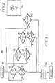
- Fig. 1 is a block diagram schematically showing an embodiment of the television signal receiving apparatus according to this invention.
- the broadcast wave from a broadcast satellite is received by a parabola antenna (BS antenna) 1.
- the received signal is frequently converted to a signal of 1 GHz band by an outdoor unit (BS converter) 2 and the frequently converted signal is then supplied to an indoor unit (BS tuner) 3.
- BS converter outdoor unit
- BS tuner indoor unit
- the signal from the outdoor unit 2 is first supplied to a tuner circuit 31.
- a channel-selection signal is supplied from a tuning microcomputer 51 for selecting a channel to the tuner circuit 31, then the turner circuit 31 selects a channel that the viewer wants to receive.
- a signal Sf which is a frequency-multiplexed signal of a video signal Sy and a modulated code signal Ss is produced from the signal of the selected channel.
- the video signal is the video signal of a base band in which the signal scramble is carried out.
- the modulated code signal Ss is the modulated signal which results from 4-phase DPSK (Differential Phase-Shift Keying)-modulating a sub-carrier with a frequency, 5.3 MHz by the audio signal and the data signal.
- the audio signal thereof is the digital signal (PCM signal) which is pulse-code-modulated by a PCM encoder and the data signal thereof is the digital signal, too.
- the data signal contains data of, for example, four kinds of program schedules and the data are each added with an identification code ID which indicates one of the PST, MST, CST and EST program schedules.
- reference numeral 52 designates ten keys used to input the numeral of the television channel upon channel selection and reference numeral 53 designates a LED (Light Emitting Diode) which displays the number of the selected channel.
- the signal Sf from the tuner circuit 31 is supplied to a low-pass filter 32 which produces the scrambled video signal Sy.
- This scrambled video signal Sy is supplied to a de-scramble circuit 33 in which it is de-scrambled.
- the video signal thus de-scrambled is supplied to an eliminating circuit 34 which eliminates an energy diffusing signal from the discrambled video signal Sy.
- the signal Sy whose energy diffusing component is removed is supplied through a gate circuit 35 and a mixing circuit 36 to a terminal 37.
- the signal Sf is also supplied to a band-pass filter 41 which produces the signal Ss.
- This signal Ss is supplied to a demodulating circuit 42 which then demodulates a PCM signal (digital audio signal) and the data signal.
- the demodulated signal is supplied to a decoder 43 in which the error correction, the separation of various signals and the like are carried out.
- the PCM signal is supplied ot a D/A (digital-to-analog) converter 44 which converts it to the stereo left and right audio signals.
- D/A digital-to-analog
- a part of the data signal is supplied from the decoder 43 to a microcomputer 61 for payment control.
- a signal indicative of the present receiving channel and the control signal are supplied from the microcomputer 51 to the microcomputer 61 so that the microcomputer 61 allows an advance payment memory 62 of the corresponding channel to be decreased in accordance with the reception contract and checks the balance of this advance payment memory 62: When the balance is decreased to the predetermined value, an alarm LED 63 flashes. If the balance of the advance payment memory 62 is reduced to zero, the control signal is suplied from the microcomputer 61 to the de-scramble circuit 33, whereby the de- scramble operation can be inhibited and thus the viewer cannot see the television program of that channel any more substantially.
- the advance payment memory 62 is made of a non-volatile memory and the data stored therein indicates the balance.
- the identification code which identifies the contract receiver and the control signal are transmitted as the data signals and on the basis of the identification code and the control signal, the advance payment memory 62 is set at a predetermined balance by the microcomputer 61 in the contract television receiver.
- reference numeral 71 designates a microcomputer for indicating messages, such as a program schedule and so on. Since this microcomputer 71 is of such a type as to display the message in a so-called video RAM (Random Access Memory) system, this microcomputer 71 is connected through a CRT (cathode ray tube) controller 72 to a display memory 73 and a character generator 74 and is further connected with a non-lock type push switch 75 which turns on and off the display of the message and a selection switch 76 which selects the program schedule in response to the Standard Time area.
- CTR cathode ray tube
- This selection switch 76 is formed as a switch of, for exmaple, a rotary type having four switching positions P, M, C and B corresponding to the PST, MST, CST and EST program schedules as shown in Fig. 2. Also, this switch 76 can be selectively changed in position by the viewer in accordance with the Standard Time area. However, this switch 76 is changed in position only when the Standard Time area is changed so that it is provided in, for example, the pocket portion at the front of the unit 3 and, this switch 76 can be changed in position by the coins and the like. In the case shown in Fig. 2, this television receiver is used in the PST Standard Time area so that the switch 76 is connected to the position P.
- the program routine 80 begins with step 81.
- step 82 it is checked whether or not the switching position of the switch 76 is at the position P.
- the program of the microcomputer 74 goes to step 83.
- step 83 of the data transmitted from the decoder 43, the identification code ID is used to check to see that the data of the PST program schedule is transmitted.
- the program goes to step 84 in which the processing for the display is carried out. Then, the data is sequentially written through the CRT controller 72 to the memory 73. When all the data are written in the memory 73, this program routine 80 ends with step 85.
- the data for the PST program schedule written in the memory 73 is read out therefrom in a time division manner by the CRT controller 72 and converted to a video signal for program schedule by using the character generator 74.
- This signal is delivered through the mixing circuit 36 to the terminal 37.
- the control signal from the microcomputer 71 is supplied to the gate circuit 35, in which the video signal Sy from the eliminating circuit 34 is blanked.
- the switch 75 is turned on once again, the video signal for the program schedule from the CRT controller 72 is blanked and the blanking of the video signal Sy in the gate circuit 35 is released and so the normal satellite broadcast is received (displayed).
- step 82 when at step 82 it is judged that the switch 76 is not at the P position, the program goes to step 86 in which it is checked to see whether the switch 76 is at the M position or not. If the switch 76 is connected to the M position, the program goes to step 87 in which it is checked to see that the program schedule data for the MST is transmitted. Then, if the MST program schedule data is confirmed by the identification code ID, the program goes to the step 84 in which the data processing similar to that of PST program schedule data is carried out.
- the program schedule data can be processsed similarly at steps 88 and 89.
- the switch position check routine is unnecessary and the program goes to step 90 to await the transmission of the EST program schedule directly.
- the program schedule data of the Standard Time area can be displayed. Accordingly, it is possible to remove such trouble that the viewer will fail to see the desired television program because the viewer gets a wrong broadcast time.
- the circuit arrangement therefor can be made very simple by only adding the switch 76 and the program routine 80 which can be manufactured at low cost.
- such a version is made possible in which, for example, the CST program schedule data is converted to a program schedule data which is suitable for other Standard Time.
- the program routine 80 shown in the flow chart of Fig. 3 instead of the program routine 80 shown in the flow chart of Fig. 3, a program routine 100 shown in Fig. 5 is used. The operation in this case will be as follows.
- a program routine 100 begins with step 101.
- the switching position of the switch 76 is checked. If now the switch 76 is connected to the P position, the processing by the microcomputer 71 goes to step 103.
- the CST program schedule data is identified by the identification code ID and then derived. Then, of the data, the data indicative of the time is converted in accordance with a difference in time between the PST and the CST. The data thus converted is sequentially written through the CRT controller 72 to the memory 73 at step 104.
- the program goes to step 105 and the routine 100 ends with the step 105. Accordingly, the PST program schedule data is written in the memory 73.
- the PST program schedule data written in the memory 73 is read out therefrom in a time division manner by the CRT controller 72 and then converted to the video signal for the program schedule by using the character generator 74.
- This signal is supplied through the mixing circuit 36 to the terminal 37.
- the control signal from the microcomputer 71 is supplied to the gate circuit 35, whereby the video signal Sy from the eliminating circuit 34 is blanked.
- the television receiver (not shown) connected to the terminal 37, there is displayed the PST program schedule data as shown in Fig. 4.
- the left-hand portion is the data which is changed from the CST program schedule data to the PST program schedule data at step 103.
- the switch 76 is connected to the M, C or E position corresponding to the Standard Time areas of MST, CST or EST, following to the step 102, step 106 and step 107 or step 108 and step 109 are executed so that of the CMT program schedule data, the data indicative of time is changed to the MST or EST.
- the switch 76 is connected to the C position, the program at step 104 is directly executed so that the data is sequentially written in the memory 73. Therefore, the MST, CST or EST program schedule data can be displayed selectively.
- the broadcasting station does not have to prepare a plurality of local program schedule and to transmit them.
Description
- This invention generally relates to a television signal receiving apparatus and more particularly is directed to a television signal receiving apparatus for receiving a satellite broadcasting signal, CATV (cable television) signals orthe like which has wide service areas having different Time Standard and has a program schedule display function.
- The invention more particularly relates to a television signal receiving apparatus having a program schedule display function, comprising a tuner means, television processing means connected to said tuner means for generating a program schedule display signal including time portions and title portions based on a program schedule data obtained through said tuner means.
- In a DBS (Direct Broadcast Satellite) system, a video signal and an audio signal are multiplexed with other data and then transmitted; while a program schedule data is transmitted as a part of such data. That is, while the satellite broadcasting is performed for a certain channel, the program schedule of such channel is also transmitted by code through the same channel.
- Accordingly, in the.DBS system, the viewer can seen the program schedule without using oser media, such as a newspaper and a magazine.
- Further, according to the DBS system, the broadcasting service can be made for a large number of areas by a single broadcast satellite. For example, the whole areas of the United States of America can be covered by a single broadcast satellite.
- However, there are four Standard Times (areas having a difference in time), for example, the PST (Pacific Standard Time), MST (Mountain Standard Time), the CST (Central Standard Time) and the EST (East Standard Time) in the U.S.A.
- Accordingly, if the satellite broadcasting transmits a program schedule of, for example, the CST, the viewers living outside the CST area must change the time on the program schedule to the standard time of the area where they live. If the viewer makes a mistake in calculating the equivalent time, the viewer cannot see the desired television program. In addition, this defect becomes serious because the satellite broadcast is usually a pay program service.
- The document "Philips Kontakte 42/77, Bildschirmnotizen, page 19," relates to a teletex system which is adapted to send additional data which are superposed to a normal television program and may be separated from the normal television program in a television signal receiving apparatus comprising digital signal processing means connected to tuner means. More particularly, the digital signal processing means may be adapted to generate a programme schedule display signal including time portions and title portions. However, the abovementioned article does not give any advice to solve the problem of the existence of different Standard Times used over an area covered by a single broadcast satellite.
- Accordingly, it is an object of this invention to provide a television signal receiving apparatus which can prevent a viewerfrom losing a chance to see a desired television program.
- It is another object of this invention to provide a television signal receiving apparatus which can be simplified in construction.
- It is a further object of this invention to provide a television signal receiving apparatus which is suitable for use in a satellite broadcast, a CATV and the like.
- According to one aspect of the present invention, there is provided a television signal receiving apparatus having a program schedule display function comprising:
- a) tuner means;
- b) television signal processing means connected to said tuner means;
- c) digital signal processing means connected to said tuner means for generating a program schedule display signal including time portions and title portions based on a program schedule data obtained through said tuner means; characterized in that it further comprises:
- d) switch means connected to said digital signal processing means for selectively generating a local program schedule display signal including revised time portions and said title portions based on the Standard Time selected by said switch means.
- These and other objects, features and advantages of the present invention will become apparent from the following detailed description of the preferred embodiments taken in conjunction with the accompanying drawings, throughout which like references designate the same elements and parts.
-
- Fig. 1 is a circuit block diagram showing an embodiment of a television signal receiving apparatus according to this invention;
- Fig. 2 is a diagram showing an example of a switch used in the present invention;
- Fig. 3 is a flow chart useful for explaining the operation of the television signal receiving apparatus of this invention shown in Fig. 1;
- Fig. 4 is a diagram showing an example of a program schedule data displayed on the picture screen of the television receiver; and
- Fig. 5 is a flow chart useful for explaining the operation of another embodiment of the television signal receiving apparatus according to the present invention.
- Now, an embodiment of a television signal receiving apparatus according to this invention will be described with reference to the attached drawings.
- Fig. 1 is a block diagram schematically showing an embodiment of the television signal receiving apparatus according to this invention.
- Referring to Fig. 1, the broadcast wave from a broadcast satellite (not shown) is received by a parabola antenna (BS antenna) 1. The received signal is frequently converted to a signal of 1 GHz band by an outdoor unit (BS converter) 2 and the frequently converted signal is then supplied to an indoor unit (BS tuner) 3.
- In the
indoor unit 3, the signal from the outdoor unit 2 is first supplied to atuner circuit 31. A channel-selection signal is supplied from atuning microcomputer 51 for selecting a channel to thetuner circuit 31, then theturner circuit 31 selects a channel that the viewer wants to receive. Then, a signal Sf which is a frequency-multiplexed signal of a video signal Sy and a modulated code signal Ss is produced from the signal of the selected channel. In this case, the video signal is the video signal of a base band in which the signal scramble is carried out. The modulated code signal Ss is the modulated signal which results from 4-phase DPSK (Differential Phase-Shift Keying)-modulating a sub-carrier with a frequency, 5.3 MHz by the audio signal and the data signal. The audio signal thereof is the digital signal (PCM signal) which is pulse-code-modulated by a PCM encoder and the data signal thereof is the digital signal, too. Further, the data signal contains data of, for example, four kinds of program schedules and the data are each added with an identification code ID which indicates one of the PST, MST, CST and EST program schedules. In Fig. 1,reference numeral 52 designates ten keys used to input the numeral of the television channel upon channel selection andreference numeral 53 designates a LED (Light Emitting Diode) which displays the number of the selected channel. - The signal Sf from the
tuner circuit 31 is supplied to a low-pass filter 32 which produces the scrambled video signal Sy. This scrambled video signal Sy is supplied to a de-scramblecircuit 33 in which it is de-scrambled. Then, the video signal thus de-scrambled is supplied to an eliminating circuit 34 which eliminates an energy diffusing signal from the discrambled video signal Sy. The signal Sy whose energy diffusing component is removed is supplied through agate circuit 35 and amixing circuit 36 to aterminal 37. - The signal Sf is also supplied to a band-
pass filter 41 which produces the signal Ss. This signal Ss is supplied to ademodulating circuit 42 which then demodulates a PCM signal (digital audio signal) and the data signal. The demodulated signal is supplied to adecoder 43 in which the error correction, the separation of various signals and the like are carried out. Then, the PCM signal is supplied ot a D/A (digital-to-analog)converter 44 which converts it to the stereo left and right audio signals. These audio signals are supplied through low-pass filters 45L and 45R toterminals - Further, at that time, a part of the data signal is supplied from the
decoder 43 to amicrocomputer 61 for payment control. Namely, a signal indicative of the present receiving channel and the control signal are supplied from themicrocomputer 51 to themicrocomputer 61 so that themicrocomputer 61 allows anadvance payment memory 62 of the corresponding channel to be decreased in accordance with the reception contract and checks the balance of this advance payment memory 62: When the balance is decreased to the predetermined value, analarm LED 63 flashes. If the balance of theadvance payment memory 62 is reduced to zero, the control signal is suplied from themicrocomputer 61 to the de-scramblecircuit 33, whereby the de- scramble operation can be inhibited and thus the viewer cannot see the television program of that channel any more substantially. - In practice, the
advance payment memory 62 is made of a non-volatile memory and the data stored therein indicates the balance. When the viewer deposits the pay charge to the bank, the identification code which identifies the contract receiver and the control signal are transmitted as the data signals and on the basis of the identification code and the control signal, theadvance payment memory 62 is set at a predetermined balance by themicrocomputer 61 in the contract television receiver. - Further,
reference numeral 71 designates a microcomputer for indicating messages, such as a program schedule and so on. Since thismicrocomputer 71 is of such a type as to display the message in a so-called video RAM (Random Access Memory) system, thismicrocomputer 71 is connected through a CRT (cathode ray tube)controller 72 to adisplay memory 73 and acharacter generator 74 and is further connected with a non-lock type push switch 75 which turns on and off the display of the message and aselection switch 76 which selects the program schedule in response to the Standard Time area. Thisselection switch 76 is formed as a switch of, for exmaple, a rotary type having four switching positions P, M, C and B corresponding to the PST, MST, CST and EST program schedules as shown in Fig. 2. Also, thisswitch 76 can be selectively changed in position by the viewer in accordance with the Standard Time area. However, thisswitch 76 is changed in position only when the Standard Time area is changed so that it is provided in, for example, the pocket portion at the front of theunit 3 and, thisswitch 76 can be changed in position by the coins and the like. In the case shown in Fig. 2, this television receiver is used in the PST Standard Time area so that theswitch 76 is connected to the position P. - To the ROM (Read Only Memory) of the
microcomputer 71, there is added aprogram routine 80 shown in Fig. 3 in addition to the message display program. - As shown in the flow chart of Fig. 3, when the switch 75 is turned ON, the
program routine 80 begins withstep 81. Atstep 82, it is checked whether or not the switching position of theswitch 76 is at the position P. In the example of Fig. 2, since theswitch 76 is changed in position to the contact P, the program of themicrocomputer 74 goes to step 83. Atstep 83, of the data transmitted from thedecoder 43, the identification code ID is used to check to see that the data of the PST program schedule is transmitted. When the data for the PST program schedule is obtained, the program goes to step 84 in which the processing for the display is carried out. Then, the data is sequentially written through theCRT controller 72 to thememory 73. When all the data are written in thememory 73, thisprogram routine 80 ends with step 85. - At that time, the data for the PST program schedule written in the
memory 73 is read out therefrom in a time division manner by theCRT controller 72 and converted to a video signal for program schedule by using thecharacter generator 74. This signal is delivered through the mixingcircuit 36 to the terminal 37. Further, at that time, the control signal from themicrocomputer 71 is supplied to thegate circuit 35, in which the video signal Sy from the eliminating circuit 34 is blanked. - Accordingly, on the television receiver (not shown) connected to the terminal 37, there is displayed the PST program schedule as shown in Fig. 4.
- If the switch 75 is turned on once again, the video signal for the program schedule from the
CRT controller 72 is blanked and the blanking of the video signal Sy in thegate circuit 35 is released and so the normal satellite broadcast is received (displayed). - Turning back to Fig. 3, when at
step 82 it is judged that theswitch 76 is not at the P position, the program goes to step 86 in which it is checked to see whether theswitch 76 is at the M position or not. If theswitch 76 is connected to the M position, the program goes to step 87 in which it is checked to see that the program schedule data for the MST is transmitted. Then, if the MST program schedule data is confirmed by the identification code ID, the program goes to the step 84 in which the data processing similar to that of PST program schedule data is carried out. - If the
switch 76 is connected to the C position, the program schedule data can be processsed similarly atsteps - If the
switch 76 is connected to the E position, the switch position check routine is unnecessary and the program goes to step 90 to await the transmission of the EST program schedule directly. - As set forth above, according to the present invention, only by switching the
switch 76 in response to the Standard Time area, the program schedule data of the Standard Time area can be displayed. Accordingly, it is possible to remove such trouble that the viewer will fail to see the desired television program because the viewer gets a wrong broadcast time. - In this case, the circuit arrangement therefor can be made very simple by only adding the
switch 76 and theprogram routine 80 which can be manufactured at low cost. - As another embodiment of the present invention, such a version is made possible in which, for example, the CST program schedule data is converted to a program schedule data which is suitable for other Standard Time. In this case, instead of the
program routine 80 shown in the flow chart of Fig. 3, aprogram routine 100 shown in Fig. 5 is used. The operation in this case will be as follows. - When the switch 75 in Fig. 1 is turned on, a
program routine 100 begins withstep 101. In thenext step 102, the switching position of theswitch 76 is checked. If now theswitch 76 is connected to the P position, the processing by themicrocomputer 71 goes to step 103. Atstep 103, of the data transmitted from thedecoder 43, the CST program schedule data is identified by the identification code ID and then derived. Then, of the data, the data indicative of the time is converted in accordance with a difference in time between the PST and the CST. The data thus converted is sequentially written through theCRT controller 72 to thememory 73 atstep 104. When all the data are written in thememory 73, the program goes to step 105 and the routine 100 ends with thestep 105. Accordingly, the PST program schedule data is written in thememory 73. - At that time, the PST program schedule data written in the
memory 73 is read out therefrom in a time division manner by theCRT controller 72 and then converted to the video signal for the program schedule by using thecharacter generator 74. This signal is supplied through the mixingcircuit 36 to the terminal 37. Further, at that time, the control signal from themicrocomputer 71 is supplied to thegate circuit 35, whereby the video signal Sy from the eliminating circuit 34 is blanked. - Accordingly, on the television receiver (not shown) connected to the terminal 37, there is displayed the PST program schedule data as shown in Fig. 4. Of the displayed program schedule data, the left-hand portion is the data which is changed from the CST program schedule data to the PST program schedule data at
step 103. - If the switch 75 is turned on once again, the video signal for the program schedule data from the
CRT controller 72 is blanked and the blanking of the signal Sy in thegate circuit 35 is released, thus the normal satellite broadcast is received (displayed). - Furthermore, if the
switch 76 is connected to the M, C or E position corresponding to the Standard Time areas of MST, CST or EST, following to thestep 102,step 106 and step 107 or step 108 and step 109 are executed so that of the CMT program schedule data, the data indicative of time is changed to the MST or EST. In the case, if theswitch 76 is connected to the C position, the program atstep 104 is directly executed so that the data is sequentially written in thememory 73. Therefore, the MST, CST or EST program schedule data can be displayed selectively. - According to the second embodiment of the present invention, the broadcasting station does not have to prepare a plurality of local program schedule and to transmit them.
- As described hereinabove, also in accordance with the second embodiment of this invention, since the program schedule data of the Standard Time can be displayed by only changing the
switch 76 in position in response to the Standard Time, it becomes possible to remove such trouble that the viewer will fail to see the desired television program because the view gets the wrong calculation of the broadcasting time.
Claims (5)
Applications Claiming Priority (4)
| Application Number | Priority Date | Filing Date | Title |
|---|---|---|---|
| JP252142/84 | 1984-11-29 | ||
| JP59252142A JPS61129984A (en) | 1984-11-29 | 1984-11-29 | Receiver for tv broadcasting |
| JP255495/84 | 1984-12-03 | ||
| JP59255495A JPS61133785A (en) | 1984-12-03 | 1984-12-03 | Receiver of television broadcast |
Publications (3)
| Publication Number | Publication Date |
|---|---|
| EP0183625A2 EP0183625A2 (en) | 1986-06-04 |
| EP0183625A3 EP0183625A3 (en) | 1987-07-29 |
| EP0183625B1 true EP0183625B1 (en) | 1990-02-28 |
Family
ID=26540567
Family Applications (1)
| Application Number | Title | Priority Date | Filing Date |
|---|---|---|---|
| EP85402346A Expired - Lifetime EP0183625B1 (en) | 1984-11-29 | 1985-11-29 | Television signal receiving apparatus |
Country Status (3)
| Country | Link |
|---|---|
| US (1) | US4691351A (en) |
| EP (1) | EP0183625B1 (en) |
| DE (1) | DE3576267D1 (en) |
Families Citing this family (114)
| Publication number | Priority date | Publication date | Assignee | Title |
|---|---|---|---|---|
| US4965825A (en) | 1981-11-03 | 1990-10-23 | The Personalized Mass Media Corporation | Signal processing apparatus and methods |
| US7831204B1 (en) | 1981-11-03 | 2010-11-09 | Personalized Media Communications, Llc | Signal processing apparatus and methods |
| USRE47642E1 (en) | 1981-11-03 | 2019-10-08 | Personalized Media Communications LLC | Signal processing apparatus and methods |
| DE3735780A1 (en) * | 1987-10-22 | 1989-05-03 | Grundig Emv | METHOD FOR PROGRAMMING A RECEIVER WITH VIDEORECORDER FOR RECORDING TELEVISION PROGRAMS BROADCASTED BY SATELLITE |
| DE3735782A1 (en) * | 1987-10-22 | 1989-05-03 | Grundig Emv | METHOD FOR PROGRAMMING A RECEIVER WITH VIDEORECORDER FOR RECORDING TELEVISION PROGRAMS BROADCASTED BY SATELLITE |
| US4907082A (en) * | 1988-05-03 | 1990-03-06 | Thomson Consumer Electronics, Inc. | Dynamic control menu for a television system or the like |
| US4977455B1 (en) * | 1988-07-15 | 1993-04-13 | System and process for vcr scheduling | |
| US5355480A (en) * | 1988-12-23 | 1994-10-11 | Scientific-Atlanta, Inc. | Storage control method and apparatus for an interactive television terminal |
| US5038211A (en) * | 1989-07-05 | 1991-08-06 | The Superguide Corporation | Method and apparatus for transmitting and receiving television program information |
| US7748018B2 (en) * | 1989-10-30 | 2010-06-29 | Starsight Telecast, Inc. | Arranging channel indicators in a television schedule system |
| US5727060A (en) * | 1989-10-30 | 1998-03-10 | Starsight Telecast, Inc. | Television schedule system |
| EP1244300B1 (en) * | 1990-09-10 | 2005-01-12 | Starsight Telecast, Inc. | Method and apparatus for accessing information about television programs |
| US5790198A (en) * | 1990-09-10 | 1998-08-04 | Starsight Telecast, Inc. | Television schedule information transmission and utilization system and process |
| US6832385B2 (en) | 1990-09-10 | 2004-12-14 | United Video Properties, Inc. | Television schedule system |
| US7210159B2 (en) * | 1994-02-18 | 2007-04-24 | Starsight Telecast, Inc. | System and method for transmitting and utilizing electronic programs guide information |
| US5619274A (en) * | 1990-09-10 | 1997-04-08 | Starsight Telecast, Inc. | Television schedule information transmission and utilization system and process |
| US5239540A (en) * | 1990-11-27 | 1993-08-24 | Scientific-Atlanta, Inc. | Method and apparatus for transmitting, receiving and communicating digital data signals with corresponding program data signals which describe the digital data signals |
| US5416508A (en) * | 1991-10-22 | 1995-05-16 | Pioneer Electronic Corporation | CATV system with transmission of program schedules, linked program broadcasts, and permissive ordering periods |
| US8352400B2 (en) | 1991-12-23 | 2013-01-08 | Hoffberg Steven M | Adaptive pattern recognition based controller apparatus and method and human-factored interface therefore |
| US5644354A (en) * | 1992-10-09 | 1997-07-01 | Prevue Interactive, Inc. | Interactive video system |
| KR960002504B1 (en) * | 1992-10-31 | 1996-02-17 | 삼성전자주식회사 | Video signal transmitting & receiving circuit and the method thereof |
| AU6352894A (en) | 1993-03-05 | 1994-09-26 | Roy J. Mankovitz | Apparatus and method using compressed codes for television program record scheduling |
| US6239794B1 (en) * | 1994-08-31 | 2001-05-29 | E Guide, Inc. | Method and system for simultaneously displaying a television program and information about the program |
| US6418556B1 (en) | 1993-09-09 | 2002-07-09 | United Video Properties, Inc. | Electronic television program guide schedule system and method |
| US5781246A (en) * | 1993-09-09 | 1998-07-14 | Alten; Jerry | Electronic television program guide schedule system and method |
| GB9400101D0 (en) * | 1994-01-05 | 1994-03-02 | Thomson Consumer Electronics | Consumer interface for a satellite television system |
| WO1995028055A1 (en) * | 1994-04-08 | 1995-10-19 | Prevue International, Inc. | Interactive scroll program guide |
| US8793738B2 (en) | 1994-05-04 | 2014-07-29 | Starsight Telecast Incorporated | Television system with downloadable features |
| US6661468B2 (en) | 1994-05-20 | 2003-12-09 | United Video Properties, Inc. | Electronic television program guide schedule system and method |
| JP3372004B2 (en) * | 1995-03-31 | 2003-01-27 | ソニー株式会社 | Electronic program guide device, electronic program guide system, and electronic program guide method |
| US5880768A (en) * | 1995-04-06 | 1999-03-09 | Prevue Networks, Inc. | Interactive program guide systems and processes |
| US5585838A (en) * | 1995-05-05 | 1996-12-17 | Microsoft Corporation | Program time guide |
| US5760821A (en) * | 1995-06-07 | 1998-06-02 | News America Publications, Inc. | Electronic program guide schedule localization system and method |
| US6769128B1 (en) | 1995-06-07 | 2004-07-27 | United Video Properties, Inc. | Electronic television program guide schedule system and method with data feed access |
| US6807558B1 (en) | 1995-06-12 | 2004-10-19 | Pointcast, Inc. | Utilization of information “push” technology |
| US5740549A (en) * | 1995-06-12 | 1998-04-14 | Pointcast, Inc. | Information and advertising distribution system and method |
| US20020178051A1 (en) | 1995-07-25 | 2002-11-28 | Thomas G. Scavone | Interactive marketing network and process using electronic certificates |
| US6732369B1 (en) * | 1995-10-02 | 2004-05-04 | Starsight Telecast, Inc. | Systems and methods for contextually linking television program information |
| US6323911B1 (en) | 1995-10-02 | 2001-11-27 | Starsight Telecast, Inc. | System and method for using television schedule information |
| US6388714B1 (en) | 1995-10-02 | 2002-05-14 | Starsight Telecast Inc | Interactive computer system for providing television schedule information |
| US9530150B2 (en) | 1996-01-19 | 2016-12-27 | Adcension, Llc | Compensation model for network services |
| US6264560B1 (en) | 1996-01-19 | 2001-07-24 | Sheldon F. Goldberg | Method and system for playing games on a network |
| US5823879A (en) | 1996-01-19 | 1998-10-20 | Sheldon F. Goldberg | Network gaming system |
| US6469753B1 (en) | 1996-05-03 | 2002-10-22 | Starsight Telecast, Inc. | Information system |
| US20030066085A1 (en) | 1996-12-10 | 2003-04-03 | United Video Properties, Inc., A Corporation Of Delaware | Internet television program guide system |
| US8635649B2 (en) | 1996-12-19 | 2014-01-21 | Gemstar Development Corporation | System and method for modifying advertisement responsive to EPG information |
| US6687906B1 (en) | 1996-12-19 | 2004-02-03 | Index Systems, Inc. | EPG with advertising inserts |
| US6526575B1 (en) * | 1997-01-07 | 2003-02-25 | United Video Properties, Inc. | System and method for distributing and broadcasting multimedia |
| US6138162A (en) * | 1997-02-11 | 2000-10-24 | Pointcast, Inc. | Method and apparatus for configuring a client to redirect requests to a caching proxy server based on a category ID with the request |
| US6173311B1 (en) | 1997-02-13 | 2001-01-09 | Pointcast, Inc. | Apparatus, method and article of manufacture for servicing client requests on a network |
| US5850218A (en) * | 1997-02-19 | 1998-12-15 | Time Warner Entertainment Company L.P. | Inter-active program guide with default selection control |
| US6061097A (en) | 1997-05-22 | 2000-05-09 | United Video Properties, Inc. | Interactive television program guide with selectable non-program options |
| BRPI9812104B1 (en) | 1997-07-21 | 2016-12-27 | Guide E Inc | method for navigating an interactive program guide |
| AU9298398A (en) | 1997-09-05 | 1999-03-29 | Prevue International, Inc. | Program guide application interface system |
| ATE217744T1 (en) | 1997-09-18 | 2002-06-15 | United Video Properties Inc | REMINDER DEVICE FOR INTERNET TELEVISION GUIDES USING ELECTRONIC MAIL |
| US6604240B2 (en) | 1997-10-06 | 2003-08-05 | United Video Properties, Inc. | Interactive television program guide system with operator showcase |
| CN1527604A (en) | 1997-12-01 | 2004-09-08 | 星视电视广播公司 | Electronic programme system having advertisement information in pull zone |
| US6445398B1 (en) | 1998-02-04 | 2002-09-03 | Corporate Media Partners | Method and system for providing user interface for electronic program guide |
| US7185355B1 (en) | 1998-03-04 | 2007-02-27 | United Video Properties, Inc. | Program guide system with preference profiles |
| US6564379B1 (en) | 1998-04-30 | 2003-05-13 | United Video Properties, Inc. | Program guide system with flip and browse advertisements |
| US20020095676A1 (en) | 1998-05-15 | 2002-07-18 | Robert A. Knee | Interactive television program guide system for determining user values for demographic categories |
| US6563515B1 (en) | 1998-05-19 | 2003-05-13 | United Video Properties, Inc. | Program guide system with video window browsing |
| US20050204388A1 (en) * | 1998-06-11 | 2005-09-15 | Knudson Edward B. | Series reminders and series recording from an interactive television program guide |
| US6442755B1 (en) | 1998-07-07 | 2002-08-27 | United Video Properties, Inc. | Electronic program guide using markup language |
| CN1867068A (en) | 1998-07-14 | 2006-11-22 | 联合视频制品公司 | Client-server based interactive television program guide system with remote server recording |
| AR020608A1 (en) | 1998-07-17 | 2002-05-22 | United Video Properties Inc | A METHOD AND A PROVISION TO SUPPLY A USER REMOTE ACCESS TO AN INTERACTIVE PROGRAMMING GUIDE BY A REMOTE ACCESS LINK |
| US6711261B1 (en) * | 1998-07-22 | 2004-03-23 | Macrovision Corp | Enhancing concealment in the presence of fine mistuning for various TV scrambling techniques |
| AR019458A1 (en) | 1998-07-23 | 2002-02-20 | United Video Properties Inc | AN INTERACTIVE TELEVISION PROGRAMMING GUIDE PROVISION THAT SERVES AS AN ENTRY |
| US20100325668A1 (en) * | 1998-08-11 | 2010-12-23 | Starsight Telecast, Inc. | Television schedule system |
| US6898762B2 (en) | 1998-08-21 | 2005-05-24 | United Video Properties, Inc. | Client-server electronic program guide |
| US6934963B1 (en) | 1998-09-22 | 2005-08-23 | United Video Properties, Inc. | Interactive television program guide with passive content |
| US6865746B1 (en) | 1998-12-03 | 2005-03-08 | United Video Properties, Inc. | Electronic program guide with related-program search feature |
| US7966078B2 (en) | 1999-02-01 | 2011-06-21 | Steven Hoffberg | Network media appliance system and method |
| MXPA01013446A (en) | 1999-06-28 | 2002-08-06 | Index Systems Inc | System and method for utilizing epg database for modifying advertisements. |
| AU5775900A (en) | 1999-06-29 | 2001-01-31 | United Video Properties, Inc. | Method and system for a video-on-demand-related interactive display within an interactive television application |
| US6404441B1 (en) | 1999-07-16 | 2002-06-11 | Jet Software, Inc. | System for creating media presentations of computer software application programs |
| US20050177850A1 (en) | 1999-10-29 | 2005-08-11 | United Video Properties, Inc. | Interactive television system with programming-related links |
| WO2001046869A2 (en) * | 1999-12-10 | 2001-06-28 | United Video Properties, Inc. | Systems and methods for coordinating interactive and passive advertisement and merchandising opportunities |
| JP2003529844A (en) | 2000-03-31 | 2003-10-07 | ユナイテッド ビデオ プロパティーズ, インコーポレイテッド | System and method for advertising linked by metadata |
| AU5005601A (en) | 2000-03-31 | 2001-10-15 | United Video Properties Inc | Systems and methods for reducing cut-offs in program recording |
| US20020029384A1 (en) | 2000-07-20 | 2002-03-07 | Griggs Theodore L. | Mechanism for distributing content data |
| US20060259926A1 (en) | 2000-07-20 | 2006-11-16 | Digital Deck, Inc. | Adaptable programming guide for networked devices |
| US20020053081A1 (en) * | 2000-10-31 | 2002-05-02 | Digitaldeck, Inc. | Adaptable programming guide for networked devices |
| KR20190096450A (en) | 2000-10-11 | 2019-08-19 | 로비 가이드스, 인크. | Systems and methods for delivering media content |
| US7493646B2 (en) | 2003-01-30 | 2009-02-17 | United Video Properties, Inc. | Interactive television systems with digital video recording and adjustable reminders |
| US20060051059A1 (en) | 2004-09-08 | 2006-03-09 | Krakirian Haig H | Video recorder having user extended and automatically extended time slots |
| US7984468B2 (en) | 2003-11-06 | 2011-07-19 | United Video Properties, Inc. | Systems and methods for providing program suggestions in an interactive television program guide |
| US8281339B1 (en) | 2004-01-12 | 2012-10-02 | United Video Properties, Inc. | Customizable flip and browse overlays in an interactive television system |
| DE102004021254A1 (en) * | 2004-04-30 | 2005-11-24 | P & L Gmbh & Co. Kg | Method for measuring a tool of a machine tool |
| US8806533B1 (en) | 2004-10-08 | 2014-08-12 | United Video Properties, Inc. | System and method for using television information codes |
| US8095951B1 (en) | 2005-05-06 | 2012-01-10 | Rovi Guides, Inc. | Systems and methods for providing a scan |
| US8640166B1 (en) | 2005-05-06 | 2014-01-28 | Rovi Guides, Inc. | Systems and methods for content surfing |
| US7788266B2 (en) | 2005-08-26 | 2010-08-31 | Veveo, Inc. | Method and system for processing ambiguous, multi-term search queries |
| US9113107B2 (en) | 2005-11-08 | 2015-08-18 | Rovi Guides, Inc. | Interactive advertising and program promotion in an interactive television system |
| US20070156521A1 (en) | 2005-12-29 | 2007-07-05 | United Video Properties, Inc. | Systems and methods for commerce in media program related merchandise |
| US7774341B2 (en) | 2006-03-06 | 2010-08-10 | Veveo, Inc. | Methods and systems for selecting and presenting content based on dynamically identifying microgenres associated with the content |
| US8316394B2 (en) | 2006-03-24 | 2012-11-20 | United Video Properties, Inc. | Interactive media guidance application with intelligent navigation and display features |
| US8799954B1 (en) | 2006-07-31 | 2014-08-05 | Rovi Guides, Inc. | Systems and methods for providing custom media content flipping |
| US8832742B2 (en) | 2006-10-06 | 2014-09-09 | United Video Properties, Inc. | Systems and methods for acquiring, categorizing and delivering media in interactive media guidance applications |
| US8490138B2 (en) * | 2007-02-23 | 2013-07-16 | Rovi Guides, Inc. | Channel searching by content type |
| US7801888B2 (en) | 2007-03-09 | 2010-09-21 | Microsoft Corporation | Media content search results ranked by popularity |
| US8407737B1 (en) | 2007-07-11 | 2013-03-26 | Rovi Guides, Inc. | Systems and methods for providing a scan transport bar |
| US20090133078A1 (en) | 2007-11-16 | 2009-05-21 | United Video Properties, Inc | Systems and methods for automatically purchasing and recording popular pay programs in an interactive media delivery system |
| US8989561B1 (en) | 2008-05-29 | 2015-03-24 | Rovi Guides, Inc. | Systems and methods for alerting users of the postponed recording of programs |
| US10063934B2 (en) | 2008-11-25 | 2018-08-28 | Rovi Technologies Corporation | Reducing unicast session duration with restart TV |
| US9166714B2 (en) | 2009-09-11 | 2015-10-20 | Veveo, Inc. | Method of and system for presenting enriched video viewing analytics |
| US8359616B2 (en) | 2009-09-30 | 2013-01-22 | United Video Properties, Inc. | Systems and methods for automatically generating advertisements using a media guidance application |
| US8775245B2 (en) | 2010-02-11 | 2014-07-08 | News America Marketing Properties, Llc | Secure coupon distribution |
| WO2012094564A1 (en) | 2011-01-06 | 2012-07-12 | Veveo, Inc. | Methods of and systems for content search based on environment sampling |
| US8805418B2 (en) | 2011-12-23 | 2014-08-12 | United Video Properties, Inc. | Methods and systems for performing actions based on location-based rules |
| US9147198B2 (en) | 2013-01-10 | 2015-09-29 | Rovi Technologies Corporation | Systems and methods for providing an interface for data driven media placement |
| US9848276B2 (en) | 2013-03-11 | 2017-12-19 | Rovi Guides, Inc. | Systems and methods for auto-configuring a user equipment device with content consumption material |
| US9288521B2 (en) | 2014-05-28 | 2016-03-15 | Rovi Guides, Inc. | Systems and methods for updating media asset data based on pause point in the media asset |
| US9948962B2 (en) | 2014-11-13 | 2018-04-17 | Time Warner Cable Enterprises Llc | Apparatus and methods for efficient delivery of electronic program guide data |
Family Cites Families (8)
| Publication number | Priority date | Publication date | Assignee | Title |
|---|---|---|---|---|
| US2875270A (en) * | 1955-06-07 | 1959-02-24 | Internat Telemeter Corp | Subscription-television system |
| US4199781A (en) * | 1974-08-20 | 1980-04-22 | Dial-A-Channel, Inc. | Program schedule displaying system |
| US4287597A (en) * | 1978-09-05 | 1981-09-01 | Arbiter Systems Incorporated | Satellite controlled clock |
| FR2457520A1 (en) * | 1979-05-23 | 1980-12-19 | Telediffusion Fse | PAGE SELECTION DEVICE FOR TELETEXT SYSTEM |
| JPS57500537A (en) * | 1980-03-31 | 1982-03-25 | ||
| US4531021A (en) * | 1980-06-19 | 1985-07-23 | Oak Industries Inc. | Two level encripting of RF signals |
| US4484217A (en) * | 1982-05-11 | 1984-11-20 | Telease, Inc. | Method and system for remote reporting, particularly for pay television billing |
| AU576787B2 (en) * | 1983-11-07 | 1988-09-08 | Sony Corporation | Satellite to cable television interface |
-
1985
- 1985-11-29 EP EP85402346A patent/EP0183625B1/en not_active Expired - Lifetime
- 1985-11-29 US US06/803,017 patent/US4691351A/en not_active Expired - Lifetime
- 1985-11-29 DE DE8585402346T patent/DE3576267D1/en not_active Expired - Lifetime
Also Published As
| Publication number | Publication date |
|---|---|
| DE3576267D1 (en) | 1990-04-05 |
| US4691351A (en) | 1987-09-01 |
| EP0183625A3 (en) | 1987-07-29 |
| EP0183625A2 (en) | 1986-06-04 |
Similar Documents
| Publication | Publication Date | Title |
|---|---|---|
| EP0183625B1 (en) | Television signal receiving apparatus | |
| US8631434B2 (en) | Method and apparatus for transmitting and downloading setup information | |
| US6583825B1 (en) | Method and apparatus for transmitting and downloading setup information | |
| US6252634B1 (en) | Method and apparatus for transmitting and downloading setup information | |
| US5469431A (en) | Method of and apparatus for channel mapping with relative service identification | |
| AU592469B2 (en) | Television transmission system | |
| US5666365A (en) | Simulcast transmission of digital programs to shared antenna receiving systems | |
| US5721584A (en) | Two-way broadcast system and receiving system | |
| US5790204A (en) | Television receiving set having multiplexed text decoder | |
| EP0489387B1 (en) | Improved receiver of teletext transmissions | |
| US20060015915A1 (en) | Emergency alert signaling method, data structure for emergency alert message, and cable TV receiver | |
| GB2186165A (en) | Improved crt video display device | |
| US20060174294A1 (en) | Digital broadcasting receiver for receiving analog broadcasting and a method thereof | |
| US6674958B2 (en) | Television apparatus control system | |
| US5592213A (en) | Receiving unit for two-way broadcasting including automatic display of operating state of a transmitting system | |
| AU656873B2 (en) | System for broadband descrambling of sync suppressed television signals | |
| WO1998016056A2 (en) | Implementation of vcr plus+ in dss receivers | |
| US7917922B1 (en) | Video input switching and signal processing apparatus | |
| JP4989819B2 (en) | Satellite TV signal receiving equipment | |
| JPS61129984A (en) | Receiver for tv broadcasting | |
| JPS61133785A (en) | Receiver of television broadcast | |
| JP2926727B2 (en) | Receiver | |
| JPH0752948B2 (en) | Specific channel frequency setting device in CATV system | |
| JPH0575950A (en) | Signal demodulation switching device | |
| JPH048995B2 (en) |
Legal Events
| Date | Code | Title | Description |
|---|---|---|---|
| PUAI | Public reference made under article 153(3) epc to a published international application that has entered the european phase |
Free format text: ORIGINAL CODE: 0009012 |
|
| AK | Designated contracting states |
Kind code of ref document: A2 Designated state(s): DE FR GB |
|
| PUAL | Search report despatched |
Free format text: ORIGINAL CODE: 0009013 |
|
| AK | Designated contracting states |
Kind code of ref document: A3 Designated state(s): DE FR GB |
|
| 17P | Request for examination filed |
Effective date: 19871020 |
|
| 17Q | First examination report despatched |
Effective date: 19880420 |
|
| GRAA | (expected) grant |
Free format text: ORIGINAL CODE: 0009210 |
|
| AK | Designated contracting states |
Kind code of ref document: B1 Designated state(s): DE FR GB |
|
| REF | Corresponds to: |
Ref document number: 3576267 Country of ref document: DE Date of ref document: 19900405 |
|
| ET | Fr: translation filed | ||
| PLBE | No opposition filed within time limit |
Free format text: ORIGINAL CODE: 0009261 |
|
| STAA | Information on the status of an ep patent application or granted ep patent |
Free format text: STATUS: NO OPPOSITION FILED WITHIN TIME LIMIT |
|
| 26N | No opposition filed | ||
| REG | Reference to a national code |
Ref country code: GB Ref legal event code: IF02 |
|
| PGFP | Annual fee paid to national office [announced via postgrant information from national office to epo] |
Ref country code: FR Payment date: 20041109 Year of fee payment: 20 |
|
| PGFP | Annual fee paid to national office [announced via postgrant information from national office to epo] |
Ref country code: GB Payment date: 20041124 Year of fee payment: 20 |
|
| PGFP | Annual fee paid to national office [announced via postgrant information from national office to epo] |
Ref country code: DE Payment date: 20041125 Year of fee payment: 20 |
|
| PG25 | Lapsed in a contracting state [announced via postgrant information from national office to epo] |
Ref country code: GB Free format text: LAPSE BECAUSE OF EXPIRATION OF PROTECTION Effective date: 20051128 |
|
| REG | Reference to a national code |
Ref country code: GB Ref legal event code: PE20 |