EP0189350A2 - Automatic eye refractive power measuring apparatus - Google Patents
Automatic eye refractive power measuring apparatus Download PDFInfo
- Publication number
- EP0189350A2 EP0189350A2 EP86400116A EP86400116A EP0189350A2 EP 0189350 A2 EP0189350 A2 EP 0189350A2 EP 86400116 A EP86400116 A EP 86400116A EP 86400116 A EP86400116 A EP 86400116A EP 0189350 A2 EP0189350 A2 EP 0189350A2
- Authority
- EP
- European Patent Office
- Prior art keywords
- measuring
- target image
- refractive power
- retina
- eye
- Prior art date
- Legal status (The legal status is an assumption and is not a legal conclusion. Google has not performed a legal analysis and makes no representation as to the accuracy of the status listed.)
- Granted
Links
Images


Classifications
-
- A—HUMAN NECESSITIES
- A61—MEDICAL OR VETERINARY SCIENCE; HYGIENE
- A61B—DIAGNOSIS; SURGERY; IDENTIFICATION
- A61B3/00—Apparatus for testing the eyes; Instruments for examining the eyes
- A61B3/10—Objective types, i.e. instruments for examining the eyes independent of the patients' perceptions or reactions
- A61B3/103—Objective types, i.e. instruments for examining the eyes independent of the patients' perceptions or reactions for determining refraction, e.g. refractometers, skiascopes
Definitions
- This invention relates to an automatic eye refractive power measuring apparatus for automatically measuring refractive power of an eye under test, and more particularly to an automatic eye refractive power measuring apparatus for detecting focussing state of a measuring target image projected to a retina of the eye unaer test by an opto-electric detector, indicating the focussing state of the measuring target image by electrical signal outputted from the opto-electric detector, and measuring refractive power of the eye unaer test.
- an automatic eye refractive power measuring apparatus for projecting a measuring target image to tne retina of an eye under test by using infrared light as invisible light and automatically measuring focussing state of the measuring target image.
- the anterior portion of the eye under test is collimated by a television monitor, etc. in order to position the eye under test.
- the measuring target image is projected on an opto-electric element for detecting only focussing state and no means is provided for a tester himself to observe the measuring target image directly.
- the tester himself cannot recognize it. Accordingly, the test result lacks dependability. Also, eveh when accommodation is acted on the eye under test, it is required to be judged from the result of the measurement. Therefore, in order to increase dependability, a high eyesight art of the tester himself is required.
- a second object of the present invention is to provide an automatic eye refractive power measuring apparatus, wherein a measurement application scope can be improved by avoiding inability of measurement due to level down of light quantity of the measuring target image on the retina which is occurred in such cases as wnen tne eye under test is suffered from a disease such as cataract, the diameter of the pupil of the eye under test is small and the like.
- the first invention comprises a projection system for projecting a measuring target image to a retina of the eye under test by invisible light; an imaging optical system for imaging a reflection image of the measuring target image projected to the retina and reflected by the retina; an opto-electric detector having a photosensitive surface disposed at imaging position and adapted to output electrical signal corresponding to the measuring target image formed on the photosensitive suriace; display means for displaying the measuring target image reflected on the retina based on the electrical signal as a visible image; and an auto-measuring portion adapted to detect focussing state of tne measuring target image projected to the retina based on the electrical signal and automatically calculate refractive power of the eye under test from the electrical signal.
- the second invention comprises a projection system for projecting a measuring target image to a retina of the eye under test by invisible light; an imaging optical system for imaging a reflection image of the measuring target image projected to the retina and reflected by the retina; an opto-electric detector having a photosensitive surface disposed at imaging position- and adapted to output electrical signal corresponding to the measuring target image formed on the photosensitive surface; display means for displaying the measuring target image reflected on the retina based on the electrical signal as a visible image; an auto-measuring portion adapted to detect focussing state of the measuring target image projected to the retina based on the electrical signal and automatically calculate refractive power of the eye under test from the electrical signal; a manual measurement portion for measuring refractive power of the eye under test by observing focussing state of tne measuring target image through tne display means; and measurement mode switching means for selectively switch the manual measurement portion and tne auto-measurement portion.
- the first invention is such constituted as mentioned above, a measuring target image projected to tne retina of tne eye under test is detected by an'opto-electric detector, the measuring target image is indicated based on electrical signal outputted from tne opto-electric detector, and such information as slit space of an image showing its focussing state is automatically measured. Accordingly, the tester can know whether tne measuring target image.projected to the retina of tne eye under test is affected by something and judge dependability of the measurement result.
- Tnat is, according to this automatic eye refractive power measuring apparatus, a comparatively more accurate eyesight test can be carried out. Further, according to tne constitution of the first invention, the slit space, etc. indicating focussing state of the measuring target image projected to the retina of the eye under test is measured by using electrical signal outputted from the opto-electric detector. Accordingly, an opto-electric detector as a detecting portion for measurement and an opto-electric detector for indicating an image are not required to provide separately. Thus, a simple constitution of the apparatus is obtainable.
- the constitution of the second invention not only auto-measurement but also manual measurement in which the tester observes the measurement target image of the display means can be effected. Accordingly, even if such an instance should arise as inability of measurement due to shortage of light quantity of the measuring target image projected on the retina caused by disease or the like of the patient, manual measurement can be easily carried out by simply switching the measuring mode without using additional measuring apparatuses. Accordingly, the measurement applicable scope can be enlarged.
- Fig. 1 illustrates an optical system of an automatic eye refractive power measuring apparatus according to the present invention.
- Fig. 1 denotes a target image projection system
- 2 denotes an imaging optical system
- 3 denotes a common use optical system commonly used for both the target image projection system 1 and the imaging optical system
- 4 denotes a chart projection system
- 5 denotes a sighting optical system
- 6 denotes an eye under test
- 7 denotes an anterior portion.
- the target image projection system 1 has such a function as to form a target image on a retina 8 by projecting target light to the retina 8 of the eye 6 under test through the common use optical system 3.
- the target image projection system 1 generally comprises a luminous element 9, a condenser lens 10, a target plate 11, reflection prisms 12, 13, a relay lens 14, a reflection prism 15, and a half moon diaphragm plate 16.
- the luminous element 9 emits infrared light as invisible light.
- the infrared light becomes parallel bundle of rays by the condenser lens 10 to illuminate the target plate 11.
- the target plate 11 is illuminatea by the infrared light to form measuring target light.
- the deflection prisms 11e through llh deflects the measuring target light to a direction perpendicular to the longitudinal direction of tne slits.
- the common use optical system 3 comprises a slit prism 17, an image rotator 18, an objective lens 19, and a beam splitter 20.
- the measuring target light from the target plate 11 is reflected by the reflection prisms 12, 13, 15, guided to the half moon diaphragm plate 16, passes through half moon holes 16a, 16b, and reflected on a reflection surface 17a of the split prism 17.
- the measuring target light reflected on the reflection surface 17a passes the pupil of the eye 6 under test through image rotator 18, objective lens 19 and beam splitter 20, and is projected on the retina 8.
- the half moon diaphragm 16 is disposed in such a manner as to be in a conjugate relation with the pupil position of the eye 6 under test in a proper position witn respect to the objective lens 19.
- the half moon diaphragm 16 is adapted to block harmful reflection light for measurement from tne anterior portion 7 of the eye 6 under test and enter the target light to the eye 6 under test.
- the image rotator 18 is adapted to rotates the measuring target image formed on the retina 8 by angle ⁇ in the meridian direction of the eye 6 under test by rotating it about an optical axis l of the common use optical system 3 by angle of ⁇ /2.
- the reflection light of the measuring target image projected on the retina 8 is guided to the imaging optical system 2 through beam splitter 20, objective lens 19, slit hole 17a of the slit prism 17, an opening 21a formed in the central portion of an opening diaphragm plate 21, relay lens 22 and reflection prism 23.
- Tne opening diaphragm 21 is disposed in a conjugate position with the pupil of the eye 6 under test and adapted to guide the reflection light passing through the central portion of the pupil to the relay lens 22.
- the imaging optical system 2 generally comprises a reflection mirror 24, a movable lens 25, a reflection mirror 26, a half mirror 27, and an imaging lens 28.
- the imaging optical system 2 is adapted to guide the reflection light of the measuring target image formed on the retina 8 to a photosensitive surface 29a of a photosensitive apparatus 29 as an opto-electric detector and forms a measuring target image thereon.
- the image rotator 18 is rotated about the optical axis l by angle of ⁇ /2 as mentioned above, the measuring target image is rotated by angle of a in its rotating direction.
- the reflection light reflected on the retina 8 passes through the image rotator 18 again, it causes the measuring target image to rotates by angle of ⁇ in the opposite direction with respect to the rotating direction of the image rotator ld and the photosensitive surface 29a of the image pick-up apparatus 29 is formed with a measuring target image facing toward a predetermined direction irrespective of the rotation of the image rotator 18.
- the cnart projection system 4 generally comprises a tungsten lamp 30 as visible light source, a condenser lens 31, a color correction filter 32, a chart plate 33, a movable lens 34, a relay lens 35, reflection mirrors 36, 37, a relay tens 38, a reflection mirror 39 r and an objective lens 40.
- the chart plate 33 is illuminated by the tungsten lamp 30 through the condenser lens 31 and the color correction filter 32.
- the wavenlgth of the light emitted from the tungsten lamp 30 is selected by the color correction filter 32 and cnly visible light of the range form 400 nm to 700 nm is permitted to pass through the color correction filter 32.
- the chart plate 33 is formed with a chart 33a shown in Fig. 3 and the light passed through tne chart 33a is guided to tne movable lens 34 andthe relay lens 33.
- the light guided to the relay lens 38 is shifted its optical path by tne reflection mirrors 36, 37, 39, passes through the relay lens 38 and tne objective lens 40, guided to the beam splitter 41 and projected toward the eye 6 under test through the beam splitter 20.
- the movable lens 34 is disposed in such a manner as to be movable in its optical axis. In objective measurement, the movable lens 34 is disposed in a position from where the eye 6 under test is far sighted or foggy sighted corresponding to refractive power of the eye 6 under test, so that the measurement can be carried out in the state that the accommodation of the eye 6 under test is removed.
- the anterior portion 7 of the eye 6 under test is illuminated by an illumination lump (not shown), and the image of the anterior portion 7 of the eye 6 under test is formed on the photosensitive surface 29a of the image pick-up apparatus 29 by the sighting optical system 5.
- Reflection bundle of ray reflected on the anterior portion 7 of the eye 6 under test is reflected by the beam splitters 20, 41 and a reflection mirror 42.
- the reflection bundle of ray reflected by the reflection mirror 42 passes through an imaging lens 43, the half mirror 27 and the image pick-up lens 28, guided onto the photosensitive surface 29a of the image pick-up apparatus 29, and an image of the anterior portion is formed on the photosensitive surface 29a of the image pick-up apparatus 29.
- the image pick-up apparatus 29 is connected to a television monitor 44, and 45 denotes a display surface.
- the display surface 45 displays a measuring target image formed on the photosensitive surface 29a as a visible image based on electrical signal from the image pick-up apparatus 29.
- 46 denotes a measuring target image formed by the imaging optical system 2
- 47 denotes an anterior portion image formea by the sighting optical system 5.
- the target image 46 displayed on the display surface 45 of the television monitor 44 is focused on the retina 8
- the target image 46 is in agreement in the space l1 between a pair of target images 46a at its upper portion and the space l2 between a pair of target images 46b at its lower portion as shown in Fig. 4.
- the measuring target image is focused at a front portion of the retina b
- tne space l1 is smaller than the space l2 as shown in Fig. 5.
- the space l1 is larger than the space l2 as shown in Fig. 6.
- tne target plate 11 In measurement of the refractive power, tne target plate 11 is moved in such a manner as to bring both the spaces l1' e2 of the measuring target image in alignment with respect to eacn other.
- the refractive power is obtained by moving quantity at that time.
- the movable lens 25 is integrally actuated while maintaining the conjugate relation with the target plate 11.
- the electrical signal of the image pick-up apparatus 29 is partly inputted in the television monitor 44 to display the image of the anterior portion. Tne remaining part of the electrical signal is inputted in an electrical signal take-off circuit 52, so that the electrical signal regarding the measuring target image is taken off based on take-off instruction signal of a take-off instruction circuit 51.
- Such taken off electrical signal is inputted in a rectangular-shaped wave generation circuit 53, and the wave shape thereof is treated and converted to a predetermined rectangular-shaped wave.
- the rectangular-shaped wave is inputted in a level interpretation device 54 and a target image position detection circuit 55.
- the electrical signal level interpretation device 54 interprets luminous level of the rectangular-shaped wave. Due to the foregoing, light quantity level of the measuring target image 46 is detected.
- Tne target image position detection circuit 55 is adapted to detects signal space of the rectangular-shaped wave signal corresponding to the space the measuring target image 46.
- output signal outputted from the electrical signal level interpretation device 54 and the target image position detection circuit 55, or respective signals as will be described later is processed by CPU 50 as a micro computer.
- CPU 50 controls a measurement mode switch 56 for switching an auto-measurement and a manual measurement, an actuation switch 57 for moving the target plate 11 and the movable lens 25, a one meridian measurement finish switch 58 for emitting the instruction signal every time measurement of one meridian is finished, a measurement finish switch 59 for emitting the instruction signal when measurement of all meridians are finished, and an auto-measurement start switch 60 for starting auto-measurement, respectively.
- CPU 50 controls an actuation control portion 61.
- the actuation control portion 61 comprises a first actuation control portion 62 for moving the target plate 11 and the movable lens 25 along the optical axis, a second actuation control portion 63 for rotating the image rotator 18 about the optical axis, and a third actuation control portion 64 for moving the movable lens 34 of the chart projection system 4 along the optical axis.
- CPU 50 runs a predetermined auto-measurement program 65 or a manual measurement program 66 which are built therein D eforehand. Respective measurement results are recorded by a printer 67 in order.
- the target plate 11 is brought to "zero diopter position" by the first actuation control portion 62, the image rotater 18 is brought to "zero degree” position by tne second actuation control portion 63, and the movable lens 34 is moved to "zero diopter" position by the third actuation control portion 64.
- a light quantity level of the measuring target image 46 is checked by the electrical signal level interpretation device 54 based on electrical signal of the image pick-up device 29 in STEP 102.
- the mode switch 56 is automatically switched to the manual measurement mode side according to the instruction of CPU 50.
- the spaces l1, l2 of the measuring target image are detected based on output of the target image position detection circuit 55 (STEP 103).
- CPU 50 calculates the difference of the spaces l1-l2 and the target plate 11 and the movable lens 25 is integrally moved along the optical path until the difference of the spaces l1 -l2 becomes "zero", that is, until the measuring target image 46 is brought to the focussing position onto the retina 8.
- the movable lens 34 of the chart projection system 4 is moved- (STEPS 103 through 106), so that the foggy state of the eye 6 under test is maintained.
- the image rotator 18 is rotated, for example, 15 times per every "six powers" in the meridian direction to be measured with the position of tne target plate 11 held stationary, and the differences of the spaces l1 - l2 corresponding to the respective rotating position are read in (STEPS 108 through 110).
- the refractive power "DO" in the " ⁇ " direction can be obtained by calculating the sum of the diopter value corresponding to the stop position of the target plate 11 and the diopter value corresponding to the value of the difference of the spaces l1 - l2.
- snown by the following formula (1) among spherical power A, astigmatism power B and astigmatism axis.
- the spherical power A, astigmatism power B and astigmatism axis ⁇ are calculated respectively based on the method for least squares (STEPS 111, 112).
- the mode switch 56 is automatically switched over to the manual measurement mode according to the instruction of CPU 50.
- the measurement values are displayed on the television monitor 44 and at the same time the measurement values are printed by the printer 67 (STEPS 114, 115), and the processing of the auto-measurement program is terminated.
- the tester since the display surface 45 of the television monitor 44 is displayed both the anterior portion image 47 and the measuring target image 46, the tester can observe the state in which the measurement is being carried out.
- STEP 116 an initial setting like STEP 101 of tne aforementioned auto-measurement mode is effected.
- the tester turns on the actuation switch 57 until both the spaces l1, l2 of the measuring target image as shown in Fig. 4 and integrally moves the target plate 11 and the movable lens 25 along the optical axis while observing the measuring target image on tne display surface 45 of the television monitor-44 (STEP 117).
- the tester turns on the 1 meridian measurement finish switch 58 to cause CPU 50 to read in the moving position of the target plate 11.
- the moving position corresponds to the refractive power in the "zero degree" meridian direction same as in the case of the auto-measurement.
- the measurement finish switch 59 is turned on to finish the measuring operation (STEP 122).
- the number of measurement is decided in advance without providing the measurement finish switch 59, so that the measurement will be automatically finished after the predetermined number of measurement is finished.
- the refractive power in the 3 meridian directions can be obtained (STEP 123), the spherical power A, astigmatism power B and astigmatism ⁇ are obtained respectively based on the aforementioned formular (1) according to the method for least squares (STEP 124). And, the measuring results of the spherical power A, astigmatism power B and astigmatism axis a are displayed on the television monitor and at the same time, they are printed out by the printer 67 (STEPS 125, 126).
Abstract
Description
- This invention relates to an automatic eye refractive power measuring apparatus for automatically measuring refractive power of an eye under test, and more particularly to an automatic eye refractive power measuring apparatus for detecting focussing state of a measuring target image projected to a retina of the eye unaer test by an opto-electric detector, indicating the focussing state of the measuring target image by electrical signal outputted from the opto-electric detector, and measuring refractive power of the eye unaer test.
- There has been known an automatic eye refractive power measuring apparatus for projecting a measuring target image to tne retina of an eye under test by using infrared light as invisible light and automatically measuring focussing state of the measuring target image. In tnis type of automatic eye refractive power measuring apparatus, the anterior portion of the eye under test is collimated by a television monitor, etc. in order to position the eye under test.
- In tne conventional automatic eye refractive power measuring apparatus, the measuring target image is projected on an opto-electric element for detecting only focussing state and no means is provided for a tester himself to observe the measuring target image directly.
- Therefore, in the conventional automatic eye refractive power measuring apparatus, even when an adverse affection is exerted on the measuring target image by reflection of the cornea and crystal body, or by reflection light reflected on the eyelashes and eyelid, the tester himself cannot recognize it. Accordingly, the test result lacks dependability. Also, eveh when accommodation is acted on the eye under test, it is required to be judged from the result of the measurement. Therefore, in order to increase dependability, a high eyesight art of the tester himself is required.
- It is therefore a first object of the present invention to provide a highly dependable automatic eye refractive power measuring apparatus, wherein a measuring target image is made as a visible image so tnat the tester himself can ooserve it and the tester can always confirm the state of the measuring target image on the retina of the eye under test during the automatic measurement of refractive power of the eye under test.
- A second object of the present invention is to provide an automatic eye refractive power measuring apparatus, wherein a measurement application scope can be improved by avoiding inability of measurement due to level down of light quantity of the measuring target image on the retina which is occurred in such cases as wnen tne eye under test is suffered from a disease such as cataract, the diameter of the pupil of the eye under test is small and the like.
- In order to achieve the above first object, the first invention comprises a projection system for projecting a measuring target image to a retina of the eye under test by invisible light; an imaging optical system for imaging a reflection image of the measuring target image projected to the retina and reflected by the retina; an opto-electric detector having a photosensitive surface disposed at imaging position and adapted to output electrical signal corresponding to the measuring target image formed on the photosensitive suriace; display means for displaying the measuring target image reflected on the retina based on the electrical signal as a visible image; and an auto-measuring portion adapted to detect focussing state of tne measuring target image projected to the retina based on the electrical signal and automatically calculate refractive power of the eye under test from the electrical signal.
- In order to achieve the above second object, the second invention comprises a projection system for projecting a measuring target image to a retina of the eye under test by invisible light; an imaging optical system for imaging a reflection image of the measuring target image projected to the retina and reflected by the retina; an opto-electric detector having a photosensitive surface disposed at imaging position- and adapted to output electrical signal corresponding to the measuring target image formed on the photosensitive surface; display means for displaying the measuring target image reflected on the retina based on the electrical signal as a visible image; an auto-measuring portion adapted to detect focussing state of the measuring target image projected to the retina based on the electrical signal and automatically calculate refractive power of the eye under test from the electrical signal; a manual measurement portion for measuring refractive power of the eye under test by observing focussing state of tne measuring target image through tne display means; and measurement mode switching means for selectively switch the manual measurement portion and tne auto-measurement portion.
- Since the first invention is such constituted as mentioned above, a measuring target image projected to tne retina of tne eye under test is detected by an'opto-electric detector, the measuring target image is indicated based on electrical signal outputted from tne opto-electric detector, and such information as slit space of an image showing its focussing state is automatically measured. Accordingly, the tester can know whether tne measuring target image.projected to the retina of tne eye under test is affected by something and judge dependability of the measurement result.
- Tnat is, according to this automatic eye refractive power measuring apparatus, a comparatively more accurate eyesight test can be carried out. Further, according to tne constitution of the first invention, the slit space, etc. indicating focussing state of the measuring target image projected to the retina of the eye under test is measured by using electrical signal outputted from the opto-electric detector. Accordingly, an opto-electric detector as a detecting portion for measurement and an opto-electric detector for indicating an image are not required to provide separately. Thus, a simple constitution of the apparatus is obtainable.
- According to the constitution of the second invention, not only auto-measurement but also manual measurement in which the tester observes the measurement target image of the display means can be effected. Accordingly, even if such an instance should arise as inability of measurement due to shortage of light quantity of the measuring target image projected on the retina caused by disease or the like of the patient, manual measurement can be easily carried out by simply switching the measuring mode without using additional measuring apparatuses. Accordingly, the measurement applicable scope can be enlarged.
-
- Fig. 1 is a schematic constitution of an optical system of an automatic eye refractive power measuring apparatus according to the present invention;
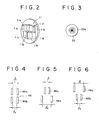
- Fig. 2 is a perspective view of a target plate constituting the optical system;
- Fig. 3 is a plan view of a chart plate constituting tne optical system;
- Figs. 4 through 6 are schematic views showing various.types of imaging state of a measuring target image formed by tne optical system;
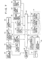
- Fig. 7 is a measurement circuit for actuating the automatic eye refractive power measuring apparatus; and
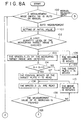
- Figs. 8(a) through 8(c) are flow charts for running a program by the measurement circuit.
- Fig. 1 illustrates an optical system of an automatic eye refractive power measuring apparatus according to the present invention.
- In Fig. 1, 1 denotes a target image projection system, 2 denotes an imaging optical system, 3 denotes a common use optical system commonly used for both the target
image projection system 1 and the imagingoptical system - The target
image projection system 1 has such a function as to form a target image on aretina 8 by projecting target light to theretina 8 of the eye 6 under test through the common useoptical system 3. The targetimage projection system 1 generally comprises aluminous element 9, acondenser lens 10, atarget plate 11,reflection prisms relay lens 14, areflection prism 15, and a halfmoon diaphragm plate 16. In this embodiment, theluminous element 9 emits infrared light as invisible light. The infrared light becomes parallel bundle of rays by thecondenser lens 10 to illuminate thetarget plate 11. Thetarget plate 11, as shown in Fig. 2, is formed with slits 11a through 11d and attacned with four deflection prisms lle through lln. Due to the foregoing, thetarget plate 11 is illuminatea by the infrared light to form measuring target light. At this time, the deflection prisms 11e through llh deflects the measuring target light to a direction perpendicular to the longitudinal direction of tne slits. - The common use
optical system 3 comprises aslit prism 17, animage rotator 18, anobjective lens 19, and a beam splitter 20. The measuring target light from thetarget plate 11 is reflected by thereflection prisms moon diaphragm plate 16, passes throughhalf moon holes reflection surface 17a of thesplit prism 17. The measuring target light reflected on thereflection surface 17a passes the pupil of the eye 6 under test throughimage rotator 18,objective lens 19 and beam splitter 20, and is projected on theretina 8. - The
half moon diaphragm 16 is disposed in such a manner as to be in a conjugate relation with the pupil position of the eye 6 under test in a proper position witn respect to theobjective lens 19. Thehalf moon diaphragm 16 is adapted to block harmful reflection light for measurement from tneanterior portion 7 of the eye 6 under test and enter the target light to the eye 6 under test. Theimage rotator 18 is adapted to rotates the measuring target image formed on theretina 8 by angle θ in the meridian direction of the eye 6 under test by rotating it about an optical axis ℓ of the common useoptical system 3 by angle of θ/2. - The reflection light of the measuring target image projected on the
retina 8 is guided to the imagingoptical system 2 through beam splitter 20,objective lens 19,slit hole 17a of theslit prism 17, an opening 21a formed in the central portion of anopening diaphragm plate 21,relay lens 22 andreflection prism 23.Tne opening diaphragm 21 is disposed in a conjugate position with the pupil of the eye 6 under test and adapted to guide the reflection light passing through the central portion of the pupil to therelay lens 22. - The imaging
optical system 2 generally comprises areflection mirror 24, amovable lens 25, areflection mirror 26, ahalf mirror 27, and animaging lens 28. The imagingoptical system 2 is adapted to guide the reflection light of the measuring target image formed on theretina 8 to aphotosensitive surface 29a of aphotosensitive apparatus 29 as an opto-electric detector and forms a measuring target image thereon. In this embociment, if theimage rotator 18 is rotated about the optical axis ℓ by angle of θ/2 as mentioned above, the measuring target image is rotated by angle of a in its rotating direction. However, since the reflection light reflected on theretina 8 passes through theimage rotator 18 again, it causes the measuring target image to rotates by angle of θ in the opposite direction with respect to the rotating direction of the image rotator ld and thephotosensitive surface 29a of the image pick-up apparatus 29 is formed with a measuring target image facing toward a predetermined direction irrespective of the rotation of theimage rotator 18. - The
cnart projection system 4 generally comprises atungsten lamp 30 as visible light source, acondenser lens 31, acolor correction filter 32, achart plate 33, amovable lens 34, arelay lens 35,reflection mirrors reflection mirror 39r and anobjective lens 40. In this embodiment, thechart plate 33 is illuminated by thetungsten lamp 30 through thecondenser lens 31 and thecolor correction filter 32. The wavenlgth of the light emitted from thetungsten lamp 30 is selected by thecolor correction filter 32 and cnly visible light of the range form 400 nm to 700 nm is permitted to pass through thecolor correction filter 32. Thechart plate 33 is formed with achart 33a shown in Fig. 3 and the light passed throughtne chart 33a is guided to tnemovable lens 34andthe relay lens 33. The light guided to the relay lens 38 is shifted its optical path bytne reflection mirrors objective lens 40, guided to thebeam splitter 41 and projected toward the eye 6 under test through the beam splitter 20. - The
movable lens 34 is disposed in such a manner as to be movable in its optical axis. In objective measurement, themovable lens 34 is disposed in a position from where the eye 6 under test is far sighted or foggy sighted corresponding to refractive power of the eye 6 under test, so that the measurement can be carried out in the state that the accommodation of the eye 6 under test is removed. - The
anterior portion 7 of the eye 6 under test is illuminated by an illumination lump (not shown), and the image of theanterior portion 7 of the eye 6 under test is formed on thephotosensitive surface 29a of the image pick-up apparatus 29 by the sightingoptical system 5. Reflection bundle of ray reflected on theanterior portion 7 of the eye 6 under test is reflected by thebeam splitters 20, 41 and areflection mirror 42. The reflection bundle of ray reflected by thereflection mirror 42 passes through animaging lens 43, thehalf mirror 27 and the image pick-up lens 28, guided onto thephotosensitive surface 29a of the image pick-up apparatus 29, and an image of the anterior portion is formed on thephotosensitive surface 29a of the image pick-up apparatus 29. - The image pick-up
apparatus 29 is connected to atelevision monitor display surface 45 displays a measuring target image formed on thephotosensitive surface 29a as a visible image based on electrical signal from the image pick-upapparatus 29. In Fig. 1, 46 denotes a measuring target image formed by the imagingoptical system optical system 5. - In this embodiment, when the
target image 46 displayed on thedisplay surface 45 of thetelevision monitor 44 is focused on theretina 8, thetarget image 46 is in agreement in the space ℓ1 between a pair oftarget images 46a at its upper portion and the space ℓ2 between a pair oftarget images 46b at its lower portion as shown in Fig. 4. For example, when the measuring target image is focused at a front portion of the retina b, tne space ℓ1 is smaller than the space ℓ2 as shown in Fig. 5. On the other nand, when the measuring target image is-focused at a rear portion of theretina 8, the space ℓ1 is larger than the space ℓ2 as shown in Fig. 6. - In measurement of the refractive power, tne
target plate 11 is moved in such a manner as to bring both the spaces ℓ1' e2 of the measuring target image in alignment with respect to eacn other. The refractive power is obtained by moving quantity at that time. In this embodiment, themovable lens 25 is integrally actuated while maintaining the conjugate relation with thetarget plate 11. - Next, a measurement circuit shown in Fig. 7 will be aescribed.
- The electrical signal of the image pick-up
apparatus 29 is partly inputted in thetelevision monitor 44 to display the image of the anterior portion. Tne remaining part of the electrical signal is inputted in an electrical signal take-off circuit 52, so that the electrical signal regarding the measuring target image is taken off based on take-off instruction signal of a take-offinstruction circuit 51. Such taken off electrical signal is inputted in a rectangular-shapedwave generation circuit 53, and the wave shape thereof is treated and converted to a predetermined rectangular-shaped wave. The rectangular-shaped wave is inputted in alevel interpretation device 54 and a target imageposition detection circuit 55. The electrical signallevel interpretation device 54 interprets luminous level of the rectangular-shaped wave. Due to the foregoing, light quantity level of the measuringtarget image 46 is detected. Tne target imageposition detection circuit 55 is adapted to detects signal space of the rectangular-shaped wave signal corresponding to the space the measuringtarget image 46. - In this embodiment, output signal outputted from the electrical signal
level interpretation device 54 and the target imageposition detection circuit 55, or respective signals as will be described later is processed byCPU 50 as a micro computer. -
CPU 50 controls ameasurement mode switch 56 for switching an auto-measurement and a manual measurement, anactuation switch 57 for moving thetarget plate 11 and themovable lens 25, a one meridianmeasurement finish switch 58 for emitting the instruction signal every time measurement of one meridian is finished, ameasurement finish switch 59 for emitting the instruction signal when measurement of all meridians are finished, and an auto-measurement start switch 60 for starting auto-measurement, respectively. In addition,CPU 50 controls anactuation control portion 61. Theactuation control portion 61 comprises a firstactuation control portion 62 for moving thetarget plate 11 and themovable lens 25 along the optical axis, a secondactuation control portion 63 for rotating theimage rotator 18 about the optical axis, and a thirdactuation control portion 64 for moving themovable lens 34 of thechart projection system 4 along the optical axis.CPU 50 runs a predetermined auto-measurement program 65 or amanual measurement program 66 which are built therein Deforehand. Respective measurement results are recorded by aprinter 67 in order. - Next, operation of the eye refractive power measuring apparatus of this constitution will be described with reference to a flow chart of Fig. 8.
- First of all, when calculative operation of
CPU 50 is started upon charging of an electric power source, etc., a switch-over state of themode switch 56 is interpreted inSTEP 100. In the case. themode switch 56 is switched over to the auto-measurement side,CPU 50 calls the auto-measurement program 65, and the following measurement is carried out based on the foregoing. - First, upon setting of an initial value in
STEP 101, thetarget plate 11 is brought to "zero diopter position" by the firstactuation control portion 62, theimage rotater 18 is brought to "zero degree" position by tne secondactuation control portion 63, and themovable lens 34 is moved to "zero diopter" position by the thirdactuation control portion 64. - Next, a light quantity level of the measuring
target image 46 is checked by the electrical signallevel interpretation device 54 based on electrical signal of the image pick-updevice 29 inSTEP 102. When the light quantity level of the measuring target image is interpreted that it does not reach the predetermined level yet here, themode switch 56 is automatically switched to the manual measurement mode side according to the instruction ofCPU 50. On the other hand, in the case the light quantity level exceeds the predetermined level, the spaces ℓ1, ℓ2 of the measuring target image are detected based on output of the target image position detection circuit 55 (STEP 103). - When the spaces ℓ1, ℓ2 are detected,
CPU 50 calculates the difference of the spaces ℓ1-ℓ2 and thetarget plate 11 and themovable lens 25 is integrally moved along the optical path until the difference of the spaces ℓ1 -ℓ2 becomes "zero", that is, until the measuringtarget image 46 is brought to the focussing position onto theretina 8. In association with the foregoing movement, themovable lens 34 of thechart projection system 4 is moved- (STEPS 103 through 106), so that the foggy state of the eye 6 under test is maintained. And, when tne difference of the spaces - ℓ2 secomes "zero", the position moved of thetarget plate 11 is read in (STEP 107), and tne refractive power of the "zero degree" meridian direction is obtained basea on the moved position. - Next, the
image rotator 18 is rotated, for example, 15 times per every "six powers" in the meridian direction to be measured with the position of tnetarget plate 11 held stationary, and the differences of the spaces ℓ1 - ℓ2 corresponding to the respective rotating position are read in (STEPS 108 through 110). The refractive power "DO" in the "θ" direction can be obtained by calculating the sum of the diopter value corresponding to the stop position of thetarget plate 11 and the diopter value corresponding to the value of the difference of the spaces ℓ1 - ℓ2. And, there is a relation as snown by the following formula (1) among spherical power A, astigmatism power B and astigmatism axis. - Dθ = A + B cos. ( θ - ℓ ) ... (1)
- Accordingly, based on the refractive powers "Dθ1 through Dθ15" obtained in the respective meridian directions (15 meridian directions), the spherical power A, astigmatism power B and astigmatism axis αare calculated respectively based on the method for least squares (STEPS 111, 112).
- Next, such obtained calculation result is compared with the measurement value and checking is made whether irregularities of the respective measurement values are within a predetermined range (STEP 113).
- When the irregularities of the measurement values are found to exceed the predetermined range by the foregoing checking, the
mode switch 56 is automatically switched over to the manual measurement mode according to the instruction ofCPU 50. - On the contrary, the irregularities are within the predetermined range, the measurement values are displayed on the
television monitor 44 and at the same time the measurement values are printed by the printer 67 (STEPS 114, 115), and the processing of the auto-measurement program is terminated. - According to this apparatus, since the
display surface 45 of thetelevision monitor 44 is displayed both theanterior portion image 47 and the measuringtarget image 46, the tester can observe the state in which the measurement is being carried out. - Next, there will be described on a case where the
mode switch 56 was switched over to the manual measurement mode side either manually or automatically. In this case,CPU 50 runs the manual measurement program. - First, in
STEP 116, an initial setting likeSTEP 101 of tne aforementioned auto-measurement mode is effected. Next, the tester turns on theactuation switch 57 until both the spaces ℓ1, ℓ2 of the measuring target image as shown in Fig. 4 and integrally moves thetarget plate 11 and themovable lens 25 along the optical axis while observing the measuring target image on tnedisplay surface 45 of the television monitor-44 (STEP 117). Upon finish of this movement, the tester turns on the 1 meridianmeasurement finish switch 58 to causeCPU 50 to read in the moving position of thetarget plate 11. The moving position corresponds to the refractive power in the "zero degree" meridian direction same as in the case of the auto-measurement. - In this case, when the 1
meridian finish switch 58 is turned on (STEP 118), a piece of * mark, for example, indicating the number of measurement is displayed on the television monitor 44 (STEP 119), the position of thetarget plate 11 is read in (STEP 120), and at the same time, theimage rotator 18 is rotated by a predetermined angle (STEP 121). Next, the tester turns on theactuation switch 57 to move thetarget plate 11 while observing the measuring target image displayed on thetelevision monitor 44 and operation such as reading-in of the moving position is repeated as in the same manner as the above mentioned STEP. At this time, every time one measuring operation is finished, one piece of * mark is aisplayed on thetelevision monitor 44. And, when at least tnree measuring operation is effected, themeasurement finish switch 59 is turned on to finish the measuring operation (STEP 122). The number of measurement is decided in advance without providing themeasurement finish switch 59, so that the measurement will be automatically finished after the predetermined number of measurement is finished. - According to the three times measuring operation, the refractive power in the 3 meridian directions can be obtained (STEP 123), the spherical power A, astigmatism power B and astigmatism α are obtained respectively based on the aforementioned formular (1) according to the method for least squares (STEP 124). And, the measuring results of the spherical power A, astigmatism power B and astigmatism axis a are displayed on the television monitor and at the same time, they are printed out by the printer 67 (
STEPS 125, 126)..
Claims (7)
Applications Claiming Priority (4)
| Application Number | Priority Date | Filing Date | Title |
|---|---|---|---|
| JP60010371A JPS61168330A (en) | 1985-01-22 | 1985-01-22 | Automatic eye refractive force measuring apparatus |
| JP10371/85 | 1985-01-22 | ||
| JP136515/85 | 1985-06-22 | ||
| JP60136515A JPS61293426A (en) | 1985-06-22 | 1985-06-22 | Apparatus for automatic measurement of eye refraction power |
Publications (3)
| Publication Number | Publication Date |
|---|---|
| EP0189350A2 true EP0189350A2 (en) | 1986-07-30 |
| EP0189350A3 EP0189350A3 (en) | 1988-05-11 |
| EP0189350B1 EP0189350B1 (en) | 1994-04-06 |
Family
ID=26345625
Family Applications (1)
| Application Number | Title | Priority Date | Filing Date |
|---|---|---|---|
| EP86400116A Expired - Lifetime EP0189350B1 (en) | 1985-01-22 | 1986-01-21 | Automatic eye refractive power measuring apparatus |
Country Status (3)
| Country | Link |
|---|---|
| US (1) | US4848895A (en) |
| EP (1) | EP0189350B1 (en) |
| DE (1) | DE3689757T2 (en) |
Cited By (4)
| Publication number | Priority date | Publication date | Assignee | Title |
|---|---|---|---|---|
| EP0349228A1 (en) * | 1988-06-27 | 1990-01-03 | Ryusyo Industrial Co., Ltd. | Apparatus for measuring refractive power of eye |
| EP0373788A2 (en) * | 1988-12-06 | 1990-06-20 | Kabushiki Kaisha TOPCON | Ocular refracting power measuring system |
| EP0479502A1 (en) * | 1990-09-29 | 1992-04-08 | Kabushiki Kaisha TOPCON | Apparatus for measuring ocular refracting power |
| EP0625332A2 (en) * | 1993-04-16 | 1994-11-23 | Canon Kabushiki Kaisha | Viewing apparatus |
Families Citing this family (2)
| Publication number | Priority date | Publication date | Assignee | Title |
|---|---|---|---|---|
| JP2761726B2 (en) * | 1988-03-11 | 1998-06-04 | 旭光学工業株式会社 | Endoscope eyepiece |
| US5617157A (en) * | 1994-06-15 | 1997-04-01 | Metaphase Ophthalmic Corp. | Computer controlled subjective refractor |
Citations (5)
| Publication number | Priority date | Publication date | Assignee | Title |
|---|---|---|---|---|
| US4162828A (en) * | 1977-09-30 | 1979-07-31 | Trachtman Joseph N | Apparatus and methods for directly measuring the refraction of the eye |
| US4306778A (en) * | 1978-11-13 | 1981-12-22 | Tokyo Kogaku Kikai Kabushiki Kaisha | Eye refractmeters using infrared rays |
| US4372655A (en) * | 1978-09-20 | 1983-02-08 | Canon Kabushiki Kaisha | Automatic eye-refractometer |
| US4412728A (en) * | 1979-08-24 | 1983-11-01 | Canon Kabushiki Kaisha | Focusing apparatus for eye-fundus examining instrument |
| EP0177005A2 (en) * | 1984-10-02 | 1986-04-09 | Kabushiki Kaisha TOPCON | Eye examining apparatus |
Family Cites Families (4)
| Publication number | Priority date | Publication date | Assignee | Title |
|---|---|---|---|---|
| US4277150A (en) * | 1977-08-24 | 1981-07-07 | Tokyo Kogaku Kikai Kabushiki Kaisha | Eye refractmeter |
| US4591247A (en) * | 1981-06-03 | 1986-05-27 | Tokyo Kogaku Kikai Kabushiki Kaisha | Eye refractometer |
| JPS59183727A (en) * | 1983-04-02 | 1984-10-18 | 株式会社トプコン | Focus alignment detector of ophthalmic machine |
| JPS60145119A (en) * | 1983-12-30 | 1985-07-31 | キヤノン株式会社 | Measurement of refractive power of eye |
-
1986
- 1986-01-21 EP EP86400116A patent/EP0189350B1/en not_active Expired - Lifetime
- 1986-01-21 DE DE3689757T patent/DE3689757T2/en not_active Expired - Fee Related
- 1986-01-22 US US06/820,793 patent/US4848895A/en not_active Expired - Lifetime
Patent Citations (5)
| Publication number | Priority date | Publication date | Assignee | Title |
|---|---|---|---|---|
| US4162828A (en) * | 1977-09-30 | 1979-07-31 | Trachtman Joseph N | Apparatus and methods for directly measuring the refraction of the eye |
| US4372655A (en) * | 1978-09-20 | 1983-02-08 | Canon Kabushiki Kaisha | Automatic eye-refractometer |
| US4306778A (en) * | 1978-11-13 | 1981-12-22 | Tokyo Kogaku Kikai Kabushiki Kaisha | Eye refractmeters using infrared rays |
| US4412728A (en) * | 1979-08-24 | 1983-11-01 | Canon Kabushiki Kaisha | Focusing apparatus for eye-fundus examining instrument |
| EP0177005A2 (en) * | 1984-10-02 | 1986-04-09 | Kabushiki Kaisha TOPCON | Eye examining apparatus |
Cited By (12)
| Publication number | Priority date | Publication date | Assignee | Title |
|---|---|---|---|---|
| EP0349228A1 (en) * | 1988-06-27 | 1990-01-03 | Ryusyo Industrial Co., Ltd. | Apparatus for measuring refractive power of eye |
| US5011276A (en) * | 1988-06-27 | 1991-04-30 | Ryusyo Industrial Co., Ltd. | Apparatus for measuring refractive power of eye |
| EP0559236A2 (en) * | 1988-06-27 | 1993-09-08 | Ryusyo Industrial Co., Ltd. | Apparatus for measuring refractive power of eye |
| EP0559235A2 (en) * | 1988-06-27 | 1993-09-08 | Ryusyo Industrial Co., Ltd. | Apparatus for measuring refractive power of eye |
| EP0559236A3 (en) * | 1988-06-27 | 1994-10-19 | Ryusyo Industrial Co | Apparatus for measuring refractive power of eye |
| EP0559235A3 (en) * | 1988-06-27 | 1994-10-26 | Ryusyo Industrial Co | Apparatus for measuring refractive power of eye |
| EP0373788A2 (en) * | 1988-12-06 | 1990-06-20 | Kabushiki Kaisha TOPCON | Ocular refracting power measuring system |
| EP0373788A3 (en) * | 1988-12-06 | 1991-04-17 | Kabushiki Kaisha TOPCON | Ocular refracting power measuring system |
| EP0479502A1 (en) * | 1990-09-29 | 1992-04-08 | Kabushiki Kaisha TOPCON | Apparatus for measuring ocular refracting power |
| EP0625332A2 (en) * | 1993-04-16 | 1994-11-23 | Canon Kabushiki Kaisha | Viewing apparatus |
| EP0625332A3 (en) * | 1993-04-16 | 1995-08-09 | Canon Kk | Viewing apparatus. |
| US5712684A (en) * | 1993-04-16 | 1998-01-27 | Canon Kabushiki Kaisha | Viewing apparatus with visual axis detector |
Also Published As
| Publication number | Publication date |
|---|---|
| DE3689757T2 (en) | 1994-11-03 |
| EP0189350B1 (en) | 1994-04-06 |
| EP0189350A3 (en) | 1988-05-11 |
| US4848895A (en) | 1989-07-18 |
| DE3689757D1 (en) | 1994-05-11 |
Similar Documents
| Publication | Publication Date | Title |
|---|---|---|
| US5909269A (en) | Ophthalmic apparatus | |
| EP0820720B1 (en) | Ophthalmic apparatus | |
| US5309186A (en) | Eye refractive power measuring apparatus having opacity discriminant function of crystalline lens | |
| EP1442698B1 (en) | Ophthalmologic apparatus | |
| EP2692283B1 (en) | Ophthalmologic apparatus and ophthalmologic method | |
| JPH04200436A (en) | Ophthamologic apparatus | |
| EP0229662B1 (en) | Surgical microscope system | |
| US4950068A (en) | Ophthalmic disease detection apparatus | |
| US4917480A (en) | Eye refractive power measuring apparatus | |
| EP0189350A2 (en) | Automatic eye refractive power measuring apparatus | |
| EP0212995A2 (en) | Sight fixation system for ophthalmic instruments | |
| JP2000245698A (en) | Instrument for measuring eye refractivity | |
| JPH067298A (en) | Ocular refractometer | |
| JPH0554771B2 (en) | ||
| US5013146A (en) | Opthalmological measurement apparatus | |
| JP2848917B2 (en) | Eye refractive power measuring device | |
| CZ6295A3 (en) | Process and apparatus for determining refractive deflection of a wheel | |
| JP3576656B2 (en) | Alignment detection device for ophthalmic instruments | |
| US4364646A (en) | Position adjusting device for ophthalmologic instrument | |
| JPH0554334B2 (en) | ||
| JP4436914B2 (en) | Eye refractive power measuring device | |
| JP2916105B2 (en) | Ophthalmic equipment | |
| JPH0554325B2 (en) | ||
| JPS61168330A (en) | Automatic eye refractive force measuring apparatus | |
| JPH0554335B2 (en) |
Legal Events
| Date | Code | Title | Description |
|---|---|---|---|
| PUAI | Public reference made under article 153(3) epc to a published international application that has entered the european phase |
Free format text: ORIGINAL CODE: 0009012 |
|
| 17P | Request for examination filed |
Effective date: 19860124 |
|
| AK | Designated contracting states |
Kind code of ref document: A2 Designated state(s): DE GB IT |
|
| PUAL | Search report despatched |
Free format text: ORIGINAL CODE: 0009013 |
|
| RHK1 | Main classification (correction) |
Ipc: A61B 3/10 |
|
| AK | Designated contracting states |
Kind code of ref document: A3 Designated state(s): DE GB IT |
|
| RAP1 | Party data changed (applicant data changed or rights of an application transferred) |
Owner name: KABUSHIKI KAISHA TOPCON |
|
| 17Q | First examination report despatched |
Effective date: 19910521 |
|
| GRAA | (expected) grant |
Free format text: ORIGINAL CODE: 0009210 |
|
| AK | Designated contracting states |
Kind code of ref document: B1 Designated state(s): DE GB IT |
|
| REF | Corresponds to: |
Ref document number: 3689757 Country of ref document: DE Date of ref document: 19940511 |
|
| ITF | It: translation for a ep patent filed |
Owner name: BARZANO' E ZANARDO MILANO S.P.A. |
|
| PLBE | No opposition filed within time limit |
Free format text: ORIGINAL CODE: 0009261 |
|
| STAA | Information on the status of an ep patent application or granted ep patent |
Free format text: STATUS: NO OPPOSITION FILED WITHIN TIME LIMIT |
|
| 26N | No opposition filed | ||
| REG | Reference to a national code |
Ref country code: GB Ref legal event code: IF02 |
|
| PGFP | Annual fee paid to national office [announced via postgrant information from national office to epo] |
Ref country code: GB Payment date: 20020114 Year of fee payment: 17 |
|
| PGFP | Annual fee paid to national office [announced via postgrant information from national office to epo] |
Ref country code: DE Payment date: 20020318 Year of fee payment: 17 |
|
| PG25 | Lapsed in a contracting state [announced via postgrant information from national office to epo] |
Ref country code: GB Free format text: LAPSE BECAUSE OF NON-PAYMENT OF DUE FEES Effective date: 20030121 |
|
| PG25 | Lapsed in a contracting state [announced via postgrant information from national office to epo] |
Ref country code: DE Free format text: LAPSE BECAUSE OF NON-PAYMENT OF DUE FEES Effective date: 20030801 |
|
| GBPC | Gb: european patent ceased through non-payment of renewal fee | ||
| PG25 | Lapsed in a contracting state [announced via postgrant information from national office to epo] |
Ref country code: IT Free format text: LAPSE BECAUSE OF NON-PAYMENT OF DUE FEES Effective date: 20050121 |