EP0190725A2 - Suspension for automotive vehicles - Google Patents
Suspension for automotive vehicles Download PDFInfo
- Publication number
- EP0190725A2 EP0190725A2 EP86101433A EP86101433A EP0190725A2 EP 0190725 A2 EP0190725 A2 EP 0190725A2 EP 86101433 A EP86101433 A EP 86101433A EP 86101433 A EP86101433 A EP 86101433A EP 0190725 A2 EP0190725 A2 EP 0190725A2
- Authority
- EP
- European Patent Office
- Prior art keywords
- axle
- plate means
- axle plate
- vehicle suspension
- plates
- Prior art date
- Legal status (The legal status is an assumption and is not a legal conclusion. Google has not performed a legal analysis and makes no representation as to the accuracy of the status listed.)
- Granted
Links
Images

Classifications
-
- B—PERFORMING OPERATIONS; TRANSPORTING
- B60—VEHICLES IN GENERAL
- B60G—VEHICLE SUSPENSION ARRANGEMENTS
- B60G9/00—Resilient suspensions of a rigid axle or axle housing for two or more wheels
- B60G9/003—Resilient suspensions of a rigid axle or axle housing for two or more wheels the axle being rigidly connected to a trailing guiding device
-
- B—PERFORMING OPERATIONS; TRANSPORTING
- B60—VEHICLES IN GENERAL
- B60G—VEHICLE SUSPENSION ARRANGEMENTS
- B60G2200/00—Indexing codes relating to suspension types
- B60G2200/30—Rigid axle suspensions
- B60G2200/31—Rigid axle suspensions with two trailing arms rigidly connected to the axle
-
- B—PERFORMING OPERATIONS; TRANSPORTING
- B60—VEHICLES IN GENERAL
- B60G—VEHICLE SUSPENSION ARRANGEMENTS
- B60G2200/00—Indexing codes relating to suspension types
- B60G2200/40—Indexing codes relating to the wheels in the suspensions
- B60G2200/445—Self-steered wheels
-
- B—PERFORMING OPERATIONS; TRANSPORTING
- B60—VEHICLES IN GENERAL
- B60G—VEHICLE SUSPENSION ARRANGEMENTS
- B60G2200/00—Indexing codes relating to suspension types
- B60G2200/40—Indexing codes relating to the wheels in the suspensions
- B60G2200/462—Toe-in/out
-
- B—PERFORMING OPERATIONS; TRANSPORTING
- B60—VEHICLES IN GENERAL
- B60G—VEHICLE SUSPENSION ARRANGEMENTS
- B60G2200/00—Indexing codes relating to suspension types
- B60G2200/40—Indexing codes relating to the wheels in the suspensions
- B60G2200/464—Caster angle
-
- B—PERFORMING OPERATIONS; TRANSPORTING
- B60—VEHICLES IN GENERAL
- B60G—VEHICLE SUSPENSION ARRANGEMENTS
- B60G2202/00—Indexing codes relating to the type of spring, damper or actuator
- B60G2202/10—Type of spring
- B60G2202/15—Fluid spring
- B60G2202/152—Pneumatic spring
-
- B—PERFORMING OPERATIONS; TRANSPORTING
- B60—VEHICLES IN GENERAL
- B60G—VEHICLE SUSPENSION ARRANGEMENTS
- B60G2204/00—Indexing codes related to suspensions per se or to auxiliary parts
- B60G2204/10—Mounting of suspension elements
- B60G2204/14—Mounting of suspension arms
- B60G2204/148—Mounting of suspension arms on the unsprung part of the vehicle, e.g. wheel knuckle or rigid axle
- B60G2204/1482—Mounting of suspension arms on the unsprung part of the vehicle, e.g. wheel knuckle or rigid axle on rigid axle by elastic mount
-
- B—PERFORMING OPERATIONS; TRANSPORTING
- B60—VEHICLES IN GENERAL
- B60G—VEHICLE SUSPENSION ARRANGEMENTS
- B60G2204/00—Indexing codes related to suspensions per se or to auxiliary parts
- B60G2204/40—Auxiliary suspension parts; Adjustment of suspensions
- B60G2204/41—Elastic mounts, e.g. bushings
-
- B—PERFORMING OPERATIONS; TRANSPORTING
- B60—VEHICLES IN GENERAL
- B60G—VEHICLE SUSPENSION ARRANGEMENTS
- B60G2204/00—Indexing codes related to suspensions per se or to auxiliary parts
- B60G2204/40—Auxiliary suspension parts; Adjustment of suspensions
- B60G2204/43—Fittings, brackets or knuckles
- B60G2204/4306—Bracket or knuckle for rigid axles, e.g. for clamping
-
- Y—GENERAL TAGGING OF NEW TECHNOLOGICAL DEVELOPMENTS; GENERAL TAGGING OF CROSS-SECTIONAL TECHNOLOGIES SPANNING OVER SEVERAL SECTIONS OF THE IPC; TECHNICAL SUBJECTS COVERED BY FORMER USPC CROSS-REFERENCE ART COLLECTIONS [XRACs] AND DIGESTS
- Y10—TECHNICAL SUBJECTS COVERED BY FORMER USPC
- Y10S—TECHNICAL SUBJECTS COVERED BY FORMER USPC CROSS-REFERENCE ART COLLECTIONS [XRACs] AND DIGESTS
- Y10S180/00—Motor vehicles
- Y10S180/905—Axles
Definitions
- the present invention relates to vehicle suspension systems and is especially adapted for the use of air springs suspensions in commercial vehicles.
- Vehicle suspensions having an arm pivotably mounted to a vehicle frame typically have an air spring mounted between a free end of the arm and the frame and an axle mounted to the top of the arm.
- An example of one such suspension is disclosed and claimed in the Masser U.S. patent 3,332,701, issued July 25, 1967.
- the axle is positioned on two bracket plates which cradle the axle.
- the brackets are rigidly secured to the axle by welding and are secured to the trailing arm by a bushed two-pin connection. It is also known to attach a flat plate between the bracket plates and weld the axle to the flat plate.
- axle clamping plates It is also known to attach axles to arms through axle clamping plates and rubber pads which wrap around the axle.
- the axle clamping plates are clamped around the rubber pads and axle with bolts.
- the trailing arms and the plates are subject to severe shear or lateral forces.
- the weld connection between the plates and axle is subject to severe torsional and shear forces as well as drive or braking torque incidental to the operation of the vehicle.
- a simple, lightweight, relatively inexpensive suspension structure for a vehicle having a frame and wheel-bearing axle is the type wherein at least two substantially rigid arms are secured to opposite sides of the frame through substantially aligned pivot mounts and a spring is preferably interposed in load- transmitting relation between the arms and the frame. At least one wheel-carrying axle extends between the arms and a bracket means secures the at least one axle to each of the arms.
- the bracket means comprises an axle plate means rigidly secured to the axle and having an elongated planar complementary surface at least partially wrapping around the axle.
- Two spaced connecting plates are secured transversely to the axle plate means and to one of the arms.
- Bracing means are rigidly secured in angular relationship to the axle plate means and the connecting plates to enhance torsional and shear resistance of the axle plate means and the connecting plates assembly.
- the bracing means comprises at least two gussets, each positioned at an acute angle to the axle plate means and to one of the connecting plates.
- At least one of the gussets is preferably curved to resiliently yield in response to torsional and shear forces exerted on the axle plate means and the respective one of the connecting plates to which it is attached.
- at least one of the gussets is flat to rigidly resist torsional movement of the axle plate means with respect to the connecting plates.
- the gussets can comprise any combination of curved and flat gussets.
- the gussets are triangularly shaped, have a first side edge which is welded to the axle plate means and a second side edge welded to a respective one of the connecting plates.
- at least two of the gussets are sufficiently large to rigidify the connecting plates.
- the gussets By adding rigidity to the axle brackets, the gussets enable the axle brackets to better withstand torsional and lateral forces exerted thereon incidental to the operation of the vehicle. However, on each axle bracket, at least one of the gussets, that gusset on which the greatest load is exerted, is curved, thereby enabling such gusset to distribute the forces exerted thereon over the adjacent area of the axle bracket.
- the axle plate means preferably has an enlarged hole extending through a central portion thereof to increase the torsional flexibility of the axle plate means.
- the hole is substantially rectangular in shape and a portion of the arm is positioned within the hole.
- the plate can be a partial cylinder to mount on a round beam or can be a partial prism to mount on a rectangular beam.
- the axle plate means extends at least 90° and preferably about 150° around the axle.
- a shock absorber is securely mounted between one of the connecting plates and the vehicle frame on each side of the vehicle.
- the shock absorber is pivotably mounted to one of the connecting plates by a shock mounting bracket.
- the connecting plates are secured to the arm through at least two bushed connections.
- each of the arms has at least two sets of transversely aligned openings and at least one elastomeric bushing extending between each set of aligned openings and positioned within the arm.
- Each of the connecting plates has at least one pair of apertures aligned with the two sets of openings and each of the bracket means is secured to one of the arms by a plurality of pins. Each of the pins extends through at least one of the elastomeric bushings and aligned set of apertures and openings.
- the pins and the pivotable mounts are coated with zinc phosphate to resist oxidation of the bushing-and-pin combination and the pivot mount.
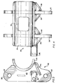
- a vehicle frame 10 has an axle 12 and ground engaging wheels 14 suspended therefrom by a suspension 16 according to the invention.
- the front of the vehicle is to the left side of the frame as viewed in Figure 1.
- Suspension 16 includes, at each side of vehicle frame 10, a trailing arm 18 pivotally mounted to a frame bracket 20 depending from frame 10 at pivotal mount 22.
- Each trailing arm extends rearwardly of the vehicle and away from its pivotal mount in a direction which is longitudinal of vehicle frame 10 and each trailing arm has a portion 24 which is secured to a pedestal 26 of an air spring 28; a top mounting plate 30 of air spring 28 being secured to vehicle frame 10.
- Axle 12 is rigidly connected to each trailing arm 18 by an axle bracket 32 straddling trailing arm 18.
- Each axle bracket comprises a semicylindrical wrapper plate 34 rigidly secured to axle 12 and having a rectangular hole 36.
- An inside plate 38 is securely attached to the inside part 40 of wrapper plate 34.
- An outside plate 42 is securely attached to the outside part 44 of wrapper plate 34.
- a shock-mounting bracket 46 is securely attached to the inner face 48 of inside plate 38.
- a first triangular gusset plate 50 is attached at a horizontal leg 52 to outside part 44' of wrapper plate 34 and at a vertical leg 54 to the outside face 56 of outside plate 42.
- a second triangular gusset plate 58 is attached at a horizontal leg 60 to outside part 44 of wrapper plate 34 and at a vertical leg 62 to, inside face 64 of outside plate 42.
- a third triangular gusset plate 66 is attached at a horizontal leg 68 to the inside part 40' of wrapper plate 34 and at a vertical leg 70 to the outer face 72 of inside plate 38.
- a fourth triangular gusset plate 74 is attached at its horizontal leg 76 to inside part 40 of wrapper plate 34 and at its vertical leg 78 to inner face 48 of inside plate 38. All of the foregoing elements of axle bracket 32 are attached by welding along adjoining surfaces.
- second gusset plate 58, third gusset plate 66 and fourth gusset plate 74 are flat plates
- first gusset plate 50 is a curved plate.
- a telescoping shock absorber 80 is connected between shock mounting bracket 46 and frame 10 to control rebound of the air spring and to limit downward swinging of the trailing arm to protect the air spring from pulling apart.
- Each set of openings 84 is aligned transversely of the trailing arm.
- Extending transversely between each set of aligned openings in trailing arm 18 is a bushing 85 of the type described in U.S. patent 3,332,701. If it is desired, two bushings, rather than one, can extend end to end transversely between each set of aligned openings.
- a pin 86 extends through each set of aligned apertures 82 and openings 84, and through at least one bushing to securely connect trailing arm 18 to axle 12.
- Each pin comprises a bolt 88, a nut 90 threadably engaging bolt 88, and two spacer washers 92, one sand- . wiched between inside face 64 of outside plate 42 and trailing arm 18, the other sandwiched between outer face 72 of inside plate 38 and trailing arm 18.
- Wrapper plate 34 is preferably designed with hole 36.
- Hole 36 provides clearance for trailing arm 18, reduces the weight of axle bracket 32 and gives axle bracket 32 flexibility during assembly.
- the trailing arms 18 neither interfere with wrapper plates 34 nor rest within holes 36, holes 36 do provide clearance for trailing arms 18 in the event that the elastomeric linings 93 of the bushings 85 wear.
- the elastomeric linings 93 thereof wear due to torsional and lateral forces exerted thereon.
- the trailing arms 18 settle and rest closer to wrapper plates 34.
- Holes 36 provide clearance for trailing arms 18 in the event of such settling.
- the apertures 82 in the inside and outside plates 38 and 42, respectively, of the axle bracket 32 are typically out of alignment with the two sets of aligned openings 84 in the trailing arm 18. Alignment of the openings with the appertures requires the wrapper plate to be somewhat flexible. This flexibility is provided, in part, by the hole 36. Welding of the wrapper plate 34 to the axle 12 increases the rigidity of the wrapper plate and thus reduces the flexibility required for alignment.
- the axle bracket 32 is first secured to the trailing arm 18. Subsequent to alignment, the axle 12 is secured to the wrapper plate 34.
- the present invention employs a relatively long air spring 28, compared to that disclosed in U.S. patent 3,332,701, and a trailing arm 18 having a horizontal part 94 and a downwardly depending part 96, in contrast to the straight trailing arm disclosed in the above-stated patent. It is understood, however, that a substantially straight trailing arm can also be used.
- the curved design of trailing arm 18 provides for sufficient space between the same and vehicle frame 10 to accommodate air spring 28 and position air spring 28 close to axle 12. By positioning air spring 28 close to axle 12, a shorter and more cost-efficient trailing arm can be used; a shorter trailing arm does not require the incorporation of structural reinforcements which might otherwise be necessary in a longer trailing arm.
- the plane defined by the two-pin connection between axle 12 and trailing arm 18 is pitched from the horizontal plane.
- the front pin 86 is connected to the horizontal part 94 of trailing arm 18 and the rear pin 86 is connected to the downwardly-depending part 96 of trailing arm 18.
- a two-pin connection is provided between axle bracket 32 and trailing arm 18.
- the two pins 86 extend generally parallel to axle 12 and are spaced apart to provide a broad base for support against lateral forces exerted on control arms 18 and against drive or brake torque on axle 12.
- the two-pin connection can be either asymmetrical or symmetrical about the center of axle 12. In the asymmetrical design, which is shown in the drawings, the distance between the center of axle 12 and the rear pin 86 is less than the distance between the center of axle 12 and the front pin 86. In the symmetrical design (not shown), the distances between the center of the axle 12 and the rear and forward pins 86 are equal.
- the gusset plates 50, 58, 66 and 74 are an important feature of the invention.
- the gusset plates add rigidity to axle bracket 32 and thereby enhance the torsional and shear strength of the axle bracket 32.
- a significant load is ordinarily exerted on the weld connection between axle 12 and axle bracket 32 during normal operation of the suspension.
- This connection is braced substantially by first gusset 50.
- first gusset 50 is curved.
- the curve design of first gusset 50 more evenly distributes the shear and torsional forces exerted on the axle bracket 32 and the weld connection between axle 12 and axle bracket 32 by slightly flexing or resiliently resisting higher loading on the suspension.
- second gusset plate 58, third gusset plate 66, fourth gusset plate 74 or any combination thereof can be curved in a manner similar to first gusset plate 50. If more rigid support is desired, all the gusset plates can be made substantially flat.
- these elements can be coated with zinc phosphate, a substance found to resist rust.
- pivotal mounts 22 can be coated with zinc phosphate.
- suspension 16 of this invention will have its greatest use with air springs, other types of springs such as coil springs or rubber springs can be used instead of air springs.
- Axle 12 can be either a.driven axle, for example on a tractor, or a dead axle, for example on a trailer.
- Suspension 16 can be mounted in single axle arrangement on a vehicle or in multiple-axle tandem arrangements.
- Axle 12 can be mounted either above trailing arms 18 or in an underslung position by merely orienting the axle brackets 32 right side up or upside down before securing them to control arms 18 by pins 86.
- the invention is equally applicable to a walking-beam type suspension wherein the beam is pivotably mounted at a central portion to a frame bracket and an axle is mounted to each end of the beam with a spring means between each end of the beam and the frame.
- the invention has been described with reference to a round axle, the invention is equally applicable to a square or rectangular axle.
- the wrapper plate 34 is shaped in a complementary manner to snugly engage the axle along a portion of its length. The wrapper plate 34 extends at least 90 around the axle and preferably about 135-180 around the axle.
Abstract
Description
- The present invention relates to vehicle suspension systems and is especially adapted for the use of air springs suspensions in commercial vehicles.
- Vehicle suspensions having an arm pivotably mounted to a vehicle frame typically have an air spring mounted between a free end of the arm and the frame and an axle mounted to the top of the arm. An example of one such suspension is disclosed and claimed in the Masser U.S. patent 3,332,701, issued July 25, 1967. In the Masser patent, the axle is positioned on two bracket plates which cradle the axle. The brackets are rigidly secured to the axle by welding and are secured to the trailing arm by a bushed two-pin connection. It is also known to attach a flat plate between the bracket plates and weld the axle to the flat plate.
- in VanDenberg, U.S. patent 4,371,190, issued February 1, 1983, a similar suspension is shown wherein a saddle plate extends between the spaced bracket plates and welds are provided between the saddle plates and the axle. Further, the axle is clamped to the saddle plates through V-bolts which are bolted to a beam housing beneath the beam or arm. The VanDenberg, U.S. patent 4,261,579, issued April 14, 1981, shows a similar structure and discloses that the welds can extend between the side plates and the axle as well. These suspensions are relatively heavy and bulky due to the many brackets, plates, beam housings and U-bolt assemblies.
- It is also known to attach axles to arms through axle clamping plates and rubber pads which wrap around the axle. The axle clamping plates are clamped around the rubber pads and axle with bolts.
- The trailing arms and the plates are subject to severe shear or lateral forces. In addition, the weld connection between the plates and axle is subject to severe torsional and shear forces as well as drive or braking torque incidental to the operation of the vehicle.
- According to the invention, there is provided a simple, lightweight, relatively inexpensive suspension structure for a vehicle having a frame and wheel-bearing axle. The suspension is the type wherein at least two substantially rigid arms are secured to opposite sides of the frame through substantially aligned pivot mounts and a spring is preferably interposed in load- transmitting relation between the arms and the frame. At least one wheel-carrying axle extends between the arms and a bracket means secures the at least one axle to each of the arms.
- According to the invention, the bracket means comprises an axle plate means rigidly secured to the axle and having an elongated planar complementary surface at least partially wrapping around the axle. Two spaced connecting plates are secured transversely to the axle plate means and to one of the arms. Bracing means are rigidly secured in angular relationship to the axle plate means and the connecting plates to enhance torsional and shear resistance of the axle plate means and the connecting plates assembly.
- Preferably, the bracing means comprises at least two gussets, each positioned at an acute angle to the axle plate means and to one of the connecting plates. At least one of the gussets is preferably curved to resiliently yield in response to torsional and shear forces exerted on the axle plate means and the respective one of the connecting plates to which it is attached. In one embodiment, at least one of the gussets is flat to rigidly resist torsional movement of the axle plate means with respect to the connecting plates. Thus, the gussets can comprise any combination of curved and flat gussets.
- Typically, the gussets are triangularly shaped, have a first side edge which is welded to the axle plate means and a second side edge welded to a respective one of the connecting plates. Desirably, at least two of the gussets are sufficiently large to rigidify the connecting plates.
- By adding rigidity to the axle brackets, the gussets enable the axle brackets to better withstand torsional and lateral forces exerted thereon incidental to the operation of the vehicle. However, on each axle bracket, at least one of the gussets, that gusset on which the greatest load is exerted, is curved, thereby enabling such gusset to distribute the forces exerted thereon over the adjacent area of the axle bracket.
- The axle plate means preferably has an enlarged hole extending through a central portion thereof to increase the torsional flexibility of the axle plate means. In one embodiment, the hole is substantially rectangular in shape and a portion of the arm is positioned within the hole. The plate can be a partial cylinder to mount on a round beam or can be a partial prism to mount on a rectangular beam. In any case, the axle plate means extends at least 90° and preferably about 150° around the axle.
- Typically, a shock absorber is securely mounted between one of the connecting plates and the vehicle frame on each side of the vehicle. Preferably, the shock absorber is pivotably mounted to one of the connecting plates by a shock mounting bracket.
- In a preferred embodiment of the invention, the connecting plates are secured to the arm through at least two bushed connections. To this end, each of the arms has at least two sets of transversely aligned openings and at least one elastomeric bushing extending between each set of aligned openings and positioned within the arm. Each of the connecting plates has at least one pair of apertures aligned with the two sets of openings and each of the bracket means is secured to one of the arms by a plurality of pins. Each of the pins extends through at least one of the elastomeric bushings and aligned set of apertures and openings.
- Further, according to the invention, the pins and the pivotable mounts are coated with zinc phosphate to resist oxidation of the bushing-and-pin combination and the pivot mount.
- The invention will now be described with reference to the drawings in which:
- Figure 1 is a fragmentary, side elevational view of a vehicle frame having mounted thereon a suspension system according to the invention;
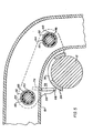
- Figure 2 is an enlarged, fragmentary, sectional view taken along lines 2-2 of Figure 1;
- Figure 3 is a side elevational view illustrating the axle bracket of the suspension shown in Figures 1 and 2;
- Figure 4 is a plan view of the axle bracket shown in Figure 3; and
- Figure 5 is a sectional view taken along lines 5-5 of Figure 2.
- Referring to the drawings and to Figure 1 in particular a
vehicle frame 10 has anaxle 12 and groundengaging wheels 14 suspended therefrom by asuspension 16 according to the invention. The front of the vehicle is to the left side of the frame as viewed in Figure 1.Suspension 16 includes, at each side ofvehicle frame 10, atrailing arm 18 pivotally mounted to aframe bracket 20 depending fromframe 10 atpivotal mount 22. Each trailing arm extends rearwardly of the vehicle and away from its pivotal mount in a direction which is longitudinal ofvehicle frame 10 and each trailing arm has a portion 24 which is secured to apedestal 26 of anair spring 28; atop mounting plate 30 ofair spring 28 being secured tovehicle frame 10. - Axle 12 is rigidly connected to each trailing
arm 18 by anaxle bracket 32 straddling trailingarm 18. Each axle bracket comprises asemicylindrical wrapper plate 34 rigidly secured toaxle 12 and having arectangular hole 36. Aninside plate 38 is securely attached to the inside part 40 ofwrapper plate 34. Anoutside plate 42 is securely attached to the outside part 44 ofwrapper plate 34. A shock-mounting bracket 46 is securely attached to theinner face 48 ofinside plate 38. A firsttriangular gusset plate 50 is attached at ahorizontal leg 52 to outside part 44' ofwrapper plate 34 and at avertical leg 54 to theoutside face 56 ofoutside plate 42. A second triangular gusset plate 58 is attached at ahorizontal leg 60 to outside part 44 ofwrapper plate 34 and at a vertical leg 62 to, inside face 64 ofoutside plate 42. A thirdtriangular gusset plate 66 is attached at ahorizontal leg 68 to the inside part 40' ofwrapper plate 34 and at avertical leg 70 to theouter face 72 ofinside plate 38. A fourthtriangular gusset plate 74 is attached at itshorizontal leg 76 to inside part 40 ofwrapper plate 34 and at itsvertical leg 78 toinner face 48 ofinside plate 38. All of the foregoing elements ofaxle bracket 32 are attached by welding along adjoining surfaces. In addition, whereas second gusset plate 58,third gusset plate 66 andfourth gusset plate 74 are flat plates,first gusset plate 50 is a curved plate. - A
telescoping shock absorber 80 is connected betweenshock mounting bracket 46 andframe 10 to control rebound of the air spring and to limit downward swinging of the trailing arm to protect the air spring from pulling apart. - Inside
plate 38 and outsideplate 42 each has a pair ofapertures 82 aligned with 2 sets ofopenings 84 in trailingarm 18. Each set ofopenings 84 is aligned transversely of the trailing arm. Extending transversely between each set of aligned openings in trailingarm 18 is abushing 85 of the type described in U.S. patent 3,332,701. If it is desired, two bushings, rather than one, can extend end to end transversely between each set of aligned openings. - A
pin 86 extends through each set of alignedapertures 82 andopenings 84, and through at least one bushing to securely connect trailingarm 18 toaxle 12. Each pin comprises abolt 88, anut 90threadably engaging bolt 88, and twospacer washers 92, one sand- . wiched between inside face 64 ofoutside plate 42 and trailingarm 18, the other sandwiched betweenouter face 72 ofinside plate 38 and trailingarm 18. -
Wrapper plate 34 is preferably designed withhole 36.Hole 36 provides clearance for trailingarm 18, reduces the weight ofaxle bracket 32 and givesaxle bracket 32 flexibility during assembly. Although, in assembled configuration, the trailingarms 18 neither interfere withwrapper plates 34 nor rest withinholes 36, holes 36 do provide clearance for trailingarms 18 in the event that theelastomeric linings 93 of thebushings 85 wear. Over the useful life of the bushings, theelastomeric linings 93 thereof wear due to torsional and lateral forces exerted thereon. As the bushings wear, the trailingarms 18 settle and rest closer towrapper plates 34.Holes 36 provide clearance for trailingarms 18 in the event of such settling. - Due to manufacturing tolerances, the
apertures 82 in the inside and outsideplates axle bracket 32 are typically out of alignment with the two sets of alignedopenings 84 in the trailingarm 18. Alignment of the openings with the appertures requires the wrapper plate to be somewhat flexible. This flexibility is provided, in part, by thehole 36. Welding of thewrapper plate 34 to theaxle 12 increases the rigidity of the wrapper plate and thus reduces the flexibility required for alignment. In view of the above, to align the two sets of openings with the apertures, during assembly, theaxle bracket 32 is first secured to the trailingarm 18. Subsequent to alignment, theaxle 12 is secured to thewrapper plate 34. - In vehicle suspension systems it is desirable to provide for adequate vertical axle movement relative to the vehicle frame and a trailing arm that is cost efficient yet rigid enough to withstand the stresses exerted thereon during vehicle operation. To achieve these goals, the present invention employs a relatively
long air spring 28, compared to that disclosed in U.S. patent 3,332,701, and a trailingarm 18 having a horizontal part 94 and a downwardly depending part 96, in contrast to the straight trailing arm disclosed in the above-stated patent. It is understood, however, that a substantially straight trailing arm can also be used. The curved design of trailingarm 18 provides for sufficient space between the same andvehicle frame 10 to accommodateair spring 28 andposition air spring 28 close toaxle 12. By positioningair spring 28 close toaxle 12, a shorter and more cost-efficient trailing arm can be used; a shorter trailing arm does not require the incorporation of structural reinforcements which might otherwise be necessary in a longer trailing arm. - To accommodate the trailing arm design, the plane defined by the two-pin connection between
axle 12 and trailingarm 18 is pitched from the horizontal plane. In addition, thefront pin 86 is connected to the horizontal part 94 of trailingarm 18 and therear pin 86 is connected to the downwardly-depending part 96 of trailingarm 18. This design obviates the need to employ a trailing arm that curves substantially at a right angle, a trailing arm that requires the incorporation of costly reinforcements. - A two-pin connection is provided between
axle bracket 32 and trailingarm 18. The twopins 86 extend generally parallel toaxle 12 and are spaced apart to provide a broad base for support against lateral forces exerted oncontrol arms 18 and against drive or brake torque onaxle 12. In the present invention, the two-pin connection can be either asymmetrical or symmetrical about the center ofaxle 12. In the asymmetrical design, which is shown in the drawings, the distance between the center ofaxle 12 and therear pin 86 is less than the distance between the center ofaxle 12 and thefront pin 86. In the symmetrical design (not shown), the distances between the center of theaxle 12 and the rear and forward pins 86 are equal. - There are a variety of forces exerted on
suspension 16 during normal operation of the vehicle. All forces onsuspension 16, with the exception of the forces controlled by air springs 28 andshock absorbers 80, are controlled by the suspension members themselves. These forces include shear and lateral forces exerted on the trailingarms 18 and theaxle bracket 32 by thepins 86. In addition, the weld connection between thewrapper plate 34 andaxle 12 is subject to severe torsional and shear forces as well as drive or braking torque incidental to the operation of the vehicle. - The
gusset plates axle bracket 32 and thereby enhance the torsional and shear strength of theaxle bracket 32. A significant load is ordinarily exerted on the weld connection betweenaxle 12 andaxle bracket 32 during normal operation of the suspension. This connection is braced substantially byfirst gusset 50. As seen in Figures 1 and 5,first gusset 50 is curved. The curve design offirst gusset 50 more evenly distributes the shear and torsional forces exerted on theaxle bracket 32 and the weld connection betweenaxle 12 andaxle bracket 32 by slightly flexing or resiliently resisting higher loading on the suspension. - In a given suspension, it may be desirable to provide less rigid support against forces exerted on
axle bracket 32 and the connection betweenaxle bracket 32 andaxle 12. In such case, second gusset plate 58,third gusset plate 66,fourth gusset plate 74 or any combination thereof can be curved in a manner similar tofirst gusset plate 50. If more rigid support is desired, all the gusset plates can be made substantially flat. - To resist oxidation of the metal lining of the
bushings 85 and pins 86 in contact therewith, these elements can be coated with zinc phosphate, a substance found to resist rust. In addition,pivotal mounts 22 can be coated with zinc phosphate. - While it is contemplated that
suspension 16 of this invention will have its greatest use with air springs, other types of springs such as coil springs or rubber springs can be used instead of air springs. -
Axle 12 can be either a.driven axle, for example on a tractor, or a dead axle, for example on a trailer.Suspension 16 can be mounted in single axle arrangement on a vehicle or in multiple-axle tandem arrangements. -
Axle 12 can be mounted either above trailingarms 18 or in an underslung position by merely orienting theaxle brackets 32 right side up or upside down before securing them to controlarms 18 bypins 86. - Whereas the invention has been described with reference to a trailing arm suspension with an axle mounted thereto, the invention is equally applicable to a walking-beam type suspension wherein the beam is pivotably mounted at a central portion to a frame bracket and an axle is mounted to each end of the beam with a spring means between each end of the beam and the frame. Further, whereas the invention has been described with reference to a round axle, the invention is equally applicable to a square or rectangular axle. In such a case, the
wrapper plate 34 is shaped in a complementary manner to snugly engage the axle along a portion of its length. Thewrapper plate 34 extends at least 90 around the axle and preferably about 135-180 around the axle. - While particular embodiments of the invention have been shown, it will be understood that the invention is not limited thereto since reasonable variations and modifications all possible within the skill of the art, particularly in light of the foregoing teachings, without departing from the spirit of the invention which is set forth in the appended claims.
Claims (11)
- The embodiments of the invention in which an exclusive property or privilege is claimed are defined as follows:
- 1. A vehicle suspension system for mounting ground-engaging wheels to a vehicle frame, the suspension system comprising at least two substantially rigid arms secured to opposite sides of the frame through substantially aligned pivot mounts; at least one wheel-carrying axle between said arms;an axle plate means rigidly secured to said axle and having an elongated planar complementary surface at least partially wrapping around said axle;two spaced connecting plates secured transversely to said axle plate means and to one of said arms; andbracing means rigidly and angularly secured to said axle plate means and to said connecting means to enhance torsional and shear resistance of said axle plate means and said connecting plates assembly, said bracing means characterized in that a gusset plate is curved to resiliently yield in response to torsional forces between said axle plate means and the respective one of said connecting plates to which it is attached.
- 2. A vehicle suspension system according to claim 1 characterized in that said bracing means comprises at least two gusset plates, each positioned at an acute angle to said axle plate means and to one of said connecting plates.
- 3. A vehicle suspension according to claim 2 characterized in that at least one of said gusset plates is flat to rigidly resist torsional movement of said axle plate means with respect to said connecting plates.
- 4. A vehicle suspension according to claim 3 characterized in that there are at least four of said gusset plates.
- 5.- A vehicle suspension according to claim 4 characterized in that each of said gusset plates is triangularly shaped, has a first side edge welded to said axle plate means and a second side edge welded to a respective one of said connecting plates.
- 6. A vehicle suspension system according to claim 5 characterized in that said axle plate means has an enlarged hole extending through a central portion thereof to increase the flexibility of said axle plate means.
- 7. A vehicle suspension system according to claim 6 characterized in that said enlarged hole is substantially rectangular in shape.
- 8. A vehicle suspension system according to claim 7 characterized in that said axle plate means extends at least 90° around said axle.
- 9. A vehicle suspension system according to claim 8 characterized in that said axle plate extends about 150° around said axle.
- 10. A vehicle suspension system according to claim 1 characterized in that said axle plate means has an enlarged hole extending through a central portion thereof to increase the flexibility of said axle plate means.
Applications Claiming Priority (2)
| Application Number | Priority Date | Filing Date | Title |
|---|---|---|---|
| US06/698,607 US4615539A (en) | 1985-02-06 | 1985-02-06 | Suspension for automotive vehicles |
| US698607 | 1985-02-06 |
Publications (3)
| Publication Number | Publication Date |
|---|---|
| EP0190725A2 true EP0190725A2 (en) | 1986-08-13 |
| EP0190725A3 EP0190725A3 (en) | 1987-08-19 |
| EP0190725B1 EP0190725B1 (en) | 1989-01-11 |
Family
ID=24805952
Family Applications (1)
| Application Number | Title | Priority Date | Filing Date |
|---|---|---|---|
| EP86101433A Expired EP0190725B1 (en) | 1985-02-06 | 1986-02-04 | Suspension for automotive vehicles |
Country Status (6)
| Country | Link |
|---|---|
| US (1) | US4615539A (en) |
| EP (1) | EP0190725B1 (en) |
| AU (1) | AU571168B2 (en) |
| CA (1) | CA1250864A (en) |
| DE (1) | DE3661702D1 (en) |
| MX (1) | MX162219A (en) |
Cited By (1)
| Publication number | Priority date | Publication date | Assignee | Title |
|---|---|---|---|---|
| EP0367986A1 (en) * | 1988-10-08 | 1990-05-16 | FELDBINDER & BECKMANN oHG | Axle suspension for a self-steering semi-trailer rear axle |
Families Citing this family (42)
| Publication number | Priority date | Publication date | Assignee | Title |
|---|---|---|---|---|
| JPS6447607A (en) * | 1987-08-17 | 1989-02-22 | Mazda Motor | Suspension device for vehicle |
| US4858949A (en) * | 1987-11-20 | 1989-08-22 | Lear Siegler Neway Corp. | Lightweight trailing arm suspension |
| US4934733A (en) * | 1989-02-22 | 1990-06-19 | Dbx Corporation | Trailer suspension apparatus |
| US5016912A (en) * | 1989-02-22 | 1991-05-21 | Dbx Corporation | Trailer suspension apparatus |
| US5039124A (en) * | 1989-11-06 | 1991-08-13 | Computer Design Chassis, Inc. | Motor vehicle frame and suspension assembly |
| US5037126A (en) * | 1990-09-07 | 1991-08-06 | The Boler Company | Lightweight beam suspension system |
| US5116075A (en) * | 1990-12-05 | 1992-05-26 | Lear Siegler Truck Products Corp. | Trailing arm suspension with wrapper compression axle mounting |
| US5112078A (en) * | 1990-12-21 | 1992-05-12 | Neway Corp. | Axle mounting assembly |
| US5288100A (en) * | 1991-03-14 | 1994-02-22 | Nai Neway, Inc. | Axle support bracket for a drive axle suspension |
| AU659853B2 (en) * | 1991-08-30 | 1995-06-01 | Neway Corporation | Adjustable bushing |
| US5413374A (en) * | 1991-08-30 | 1995-05-09 | Nai Neway, Inc. | Adjustable bushing |
| US5275430A (en) * | 1992-02-05 | 1994-01-04 | Dbx Engineering Corporation | Trailer suspension apparatus |
| US5778798A (en) * | 1995-02-24 | 1998-07-14 | Vandenberg; Ervin K. | Lift axle suspension for large volume trailers |
| US6241266B1 (en) * | 1995-08-03 | 2001-06-05 | Holland Neway International, Inc. | Trailing arm suspension with wrapper compression axle mounting and articulated axle mounting |
| US5836599A (en) * | 1997-01-21 | 1998-11-17 | Ford Global Technologies, Inc. | Independent suspension apparatus for a wheeled vehicle |
| US6398251B1 (en) | 1997-01-31 | 2002-06-04 | Dallas Smith Corporation | Axleless vehicle suspension system |
| US5839750A (en) * | 1997-01-31 | 1998-11-24 | Dbx Engineering Corporation | Leaf spring wheel suspension system |
| US5951032A (en) * | 1998-01-29 | 1999-09-14 | Timbren Industries Incorporated | Air suspension system |
| BR9815925A (en) | 1998-07-02 | 2001-02-20 | Boler Co | Rear arm axle / suspension system |
| US6209895B1 (en) | 1998-12-03 | 2001-04-03 | Reyco Industries, Inc. | Axle suspension system for a wheeled vehicle |
| US6626454B1 (en) * | 2000-06-19 | 2003-09-30 | Dana Corporation | Trailer suspension |
| US6508393B2 (en) | 2001-03-22 | 2003-01-21 | Watson & Chalin Manufacturing, Inc. | Suspension system including arm having zero clearance axle connection |
| US7178817B1 (en) | 2002-11-01 | 2007-02-20 | Monaco Coach Corporation | Trailing arm suspension system |
| WO2005039900A2 (en) | 2003-10-24 | 2005-05-06 | Aloha, Llc | Suspensions for low floor vehicles |
| US20060113741A1 (en) * | 2004-12-01 | 2006-06-01 | Chalin Thomas N | Suspension system having high strength arm to axle connection |
| US7347435B2 (en) * | 2005-01-14 | 2008-03-25 | Watson & Chalin Manufacturing, Inc. | Suspension system having reduced weight arm construction |
| US7618049B2 (en) * | 2006-09-15 | 2009-11-17 | Arvinmeritor Technology, Llc | Trailing arm suspension |
| US20090072505A1 (en) * | 2007-09-13 | 2009-03-19 | Tuthill Corporation | Vehicle suspension with trailing arm and axle assembly and method |
| ITTO20070735A1 (en) * | 2007-10-18 | 2009-04-19 | Sistemi Sospensioni Spa | REAR SUSPENSION FOR MOTOR VEHICLES. |
| BRPI0800539B1 (en) * | 2008-01-23 | 2019-08-06 | Kll Equipamentos Para Transporte Ltda | GLOVE APPLIED TO THE UNIT OF THE ARM AND SHAFT BEAM IN PNEUMATIC SUSPENSIONS |
| WO2009111006A2 (en) * | 2008-03-05 | 2009-09-11 | Tuthill Corporation | Suspension system with swaged axle and welded arm brackets and method of manufacture |
| CA2714255A1 (en) | 2009-09-01 | 2011-03-01 | Timbren Industries Inc. | Suspension mechanism |
| WO2011053570A1 (en) * | 2009-10-26 | 2011-05-05 | Hendrickson Usa, L.L.C. | Heavy-duty axle-to-beam connection |
| WO2011112677A1 (en) * | 2010-03-10 | 2011-09-15 | Hendrickson Usa, L.L.C. | Heavy-duty axle/suspension system |
| CN103403387B (en) * | 2011-01-28 | 2016-02-10 | 亨德里克森美国有限责任公司 | For the vibrations fitting seat supporting component of heavy-duty vehicle |
| US8998229B2 (en) * | 2011-08-31 | 2015-04-07 | John Michel | I-beam axle suspension system |
| MX367207B (en) | 2012-09-17 | 2019-08-08 | Hendrickson Usa Llc | Heavy-duty axle/suspension system. |
| DE102014218325B4 (en) * | 2014-09-12 | 2021-10-28 | Saf-Holland Gmbh | Axle unit |
| US11118645B2 (en) | 2018-08-30 | 2021-09-14 | Hendrickson Usa, L.L.C. | Axle spring seat attachment assembly |
| US11130379B2 (en) | 2018-08-30 | 2021-09-28 | Hendrickson Usa, L.L.C. | Axle-to-beam connection for heavy-duty vehicles |
| US11479071B2 (en) * | 2019-03-01 | 2022-10-25 | Kubota Corporation | Work vehicle and front grill of work vehicle |
| US11584178B1 (en) | 2022-08-02 | 2023-02-21 | Manfred Bosco | Independent suspension apparatus for a trailer |
Citations (4)
| Publication number | Priority date | Publication date | Assignee | Title |
|---|---|---|---|---|
| US3332701A (en) * | 1965-06-10 | 1967-07-25 | Neway Equipment Co | Suspension for automotive vehicles |
| US3801086A (en) * | 1972-08-23 | 1974-04-02 | J Raidel | Vehicle air spring suspension assembly |
| US4261597A (en) * | 1979-04-12 | 1981-04-14 | Turner Quick-Lift Corporation | Axle alignment mechanism and method |
| US4371190A (en) * | 1980-01-28 | 1983-02-01 | Turner Quick-Lift Corporation | Axle suspension system |
Family Cites Families (1)
| Publication number | Priority date | Publication date | Assignee | Title |
|---|---|---|---|---|
| US3502348A (en) * | 1968-05-23 | 1970-03-24 | Hil Air Corp | Suspension system for auxiliary axle unit |
-
1985
- 1985-02-06 US US06/698,607 patent/US4615539A/en not_active Expired - Lifetime
-
1986
- 1986-01-23 CA CA000500187A patent/CA1250864A/en not_active Expired
- 1986-01-31 AU AU52965/86A patent/AU571168B2/en not_active Ceased
- 1986-02-04 EP EP86101433A patent/EP0190725B1/en not_active Expired
- 1986-02-04 DE DE8686101433T patent/DE3661702D1/en not_active Expired
- 1986-02-04 MX MX1458A patent/MX162219A/en unknown
Patent Citations (4)
| Publication number | Priority date | Publication date | Assignee | Title |
|---|---|---|---|---|
| US3332701A (en) * | 1965-06-10 | 1967-07-25 | Neway Equipment Co | Suspension for automotive vehicles |
| US3801086A (en) * | 1972-08-23 | 1974-04-02 | J Raidel | Vehicle air spring suspension assembly |
| US4261597A (en) * | 1979-04-12 | 1981-04-14 | Turner Quick-Lift Corporation | Axle alignment mechanism and method |
| US4371190A (en) * | 1980-01-28 | 1983-02-01 | Turner Quick-Lift Corporation | Axle suspension system |
Cited By (1)
| Publication number | Priority date | Publication date | Assignee | Title |
|---|---|---|---|---|
| EP0367986A1 (en) * | 1988-10-08 | 1990-05-16 | FELDBINDER & BECKMANN oHG | Axle suspension for a self-steering semi-trailer rear axle |
Also Published As
| Publication number | Publication date |
|---|---|
| DE3661702D1 (en) | 1989-02-16 |
| MX162219A (en) | 1991-04-10 |
| EP0190725B1 (en) | 1989-01-11 |
| US4615539A (en) | 1986-10-07 |
| AU5296586A (en) | 1986-08-14 |
| AU571168B2 (en) | 1988-03-31 |
| CA1250864A (en) | 1989-03-07 |
| EP0190725A3 (en) | 1987-08-19 |
Similar Documents
| Publication | Publication Date | Title |
|---|---|---|
| EP0190725B1 (en) | Suspension for automotive vehicles | |
| US5203585A (en) | Split-beam suspension system | |
| CA2108724C (en) | Axle suspension system | |
| CA2759808C (en) | Suspension system for heavy and vocational vehicles | |
| AU703205B2 (en) | Linkage suspension system | |
| US4813704A (en) | Dual strut wheel suspension | |
| CA2043786C (en) | Lightweight beam suspension system | |
| US3332701A (en) | Suspension for automotive vehicles | |
| AU2002248483B2 (en) | Vehicle suspension | |
| US5465997A (en) | Rubber spring tag axle supension | |
| US4722549A (en) | Suspension system with universal pivot connection between axle seat and torque rod | |
| US6808192B1 (en) | Trailing arm suspension | |
| EP1663677A1 (en) | Rigid axle for a vehicle, comprising integrated trailing arms | |
| EP1250237B1 (en) | Trailing arm suspension | |
| US7549659B2 (en) | Multiple trailing arm suspension | |
| CN109484118B (en) | Composite material spring CTBA suspension system | |
| US4405154A (en) | Multi-axle equilized suspension system | |
| NZ215090A (en) | Vehicle suspension system; axle connected to pivoting arms using braced plates with mounting lugs | |
| CA2350893A1 (en) | Trailer suspension | |
| NZ272361A (en) | Vehicle axle rigidly attached to beam allowing for attaching braking mechanism to beam, rather than axle | |
| MXPA93006307A (en) | Axle suspension system for overhead vehicles |
Legal Events
| Date | Code | Title | Description |
|---|---|---|---|
| PUAI | Public reference made under article 153(3) epc to a published international application that has entered the european phase |
Free format text: ORIGINAL CODE: 0009012 |
|
| AK | Designated contracting states |
Kind code of ref document: A2 Designated state(s): DE FR GB |
|
| PUAL | Search report despatched |
Free format text: ORIGINAL CODE: 0009013 |
|
| AK | Designated contracting states |
Kind code of ref document: A3 Designated state(s): DE FR GB |
|
| 17P | Request for examination filed |
Effective date: 19871105 |
|
| 17Q | First examination report despatched |
Effective date: 19880217 |
|
| GRAA | (expected) grant |
Free format text: ORIGINAL CODE: 0009210 |
|
| RAP1 | Party data changed (applicant data changed or rights of an application transferred) |
Owner name: LEAR SIEGLER TRUCK PRODUCTS CORP. |
|
| AK | Designated contracting states |
Kind code of ref document: B1 Designated state(s): DE FR GB |
|
| REF | Corresponds to: |
Ref document number: 3661702 Country of ref document: DE Date of ref document: 19890216 |
|
| ET | Fr: translation filed | ||
| PLBE | No opposition filed within time limit |
Free format text: ORIGINAL CODE: 0009261 |
|
| STAA | Information on the status of an ep patent application or granted ep patent |
Free format text: STATUS: NO OPPOSITION FILED WITHIN TIME LIMIT |
|
| 26N | No opposition filed | ||
| PGFP | Annual fee paid to national office [announced via postgrant information from national office to epo] |
Ref country code: GB Payment date: 19960111 Year of fee payment: 11 |
|
| PG25 | Lapsed in a contracting state [announced via postgrant information from national office to epo] |
Ref country code: GB Effective date: 19970204 |
|
| GBPC | Gb: european patent ceased through non-payment of renewal fee |
Effective date: 19970204 |
|
| PGFP | Annual fee paid to national office [announced via postgrant information from national office to epo] |
Ref country code: FR Payment date: 19980212 Year of fee payment: 13 |
|
| PGFP | Annual fee paid to national office [announced via postgrant information from national office to epo] |
Ref country code: DE Payment date: 19980330 Year of fee payment: 13 |
|
| REG | Reference to a national code |
Ref country code: GB Ref legal event code: 728V |
|
| REG | Reference to a national code |
Ref country code: GB Ref legal event code: 7281 |
|
| PG25 | Lapsed in a contracting state [announced via postgrant information from national office to epo] |
Ref country code: FR Free format text: LAPSE BECAUSE OF NON-PAYMENT OF DUE FEES Effective date: 19991029 |
|
| PG25 | Lapsed in a contracting state [announced via postgrant information from national office to epo] |
Ref country code: DE Free format text: LAPSE BECAUSE OF NON-PAYMENT OF DUE FEES Effective date: 19991201 |
|
| REG | Reference to a national code |
Ref country code: FR Ref legal event code: ST |