EP0195321A2 - Automatic centrifugal balancing mechanism - Google Patents
Automatic centrifugal balancing mechanism Download PDFInfo
- Publication number
- EP0195321A2 EP0195321A2 EP86102975A EP86102975A EP0195321A2 EP 0195321 A2 EP0195321 A2 EP 0195321A2 EP 86102975 A EP86102975 A EP 86102975A EP 86102975 A EP86102975 A EP 86102975A EP 0195321 A2 EP0195321 A2 EP 0195321A2
- Authority
- EP
- European Patent Office
- Prior art keywords
- plate member
- holding means
- counterweight
- axis
- centrifugal force
- Prior art date
- Legal status (The legal status is an assumption and is not a legal conclusion. Google has not performed a legal analysis and makes no representation as to the accuracy of the status listed.)
- Granted
Links
Images

Classifications
-
- B—PERFORMING OPERATIONS; TRANSPORTING
- B04—CENTRIFUGAL APPARATUS OR MACHINES FOR CARRYING-OUT PHYSICAL OR CHEMICAL PROCESSES
- B04B—CENTRIFUGES
- B04B9/00—Drives specially designed for centrifuges; Arrangement or disposition of transmission gearing; Suspending or balancing rotary bowls
- B04B9/14—Balancing rotary bowls ; Schrappers
Definitions
- This invention relates to apparatus for , chemical testing, and more specifically to an automatic balancing mechanism for use with centrifuge apparatus used in such chemical testing.
- the centrifuge apparatus includes a plate member adapted to rotate at high speeds about an axis on which there is mounted one or more holding member(s) capable of receiving a sample processor card which rotates with the plate member.
- the holding member is adapted to receive a sample processor card; the card defines a series of channels and/or chambers through which liquid undergoing testing can be moved under the influence of centrifugal force.
- the holding member is itself mounted for rotation relative to the plate member so that the direction of centrifugal force exerted on the sample processor card can be changed to control the flow of liquids therethrough, thereby to effect transfer and ultimate mixing of liquids from one chamber in the processor card to another.
- the sample processor card can be provided with a reagent for mixing with, for example, a blood sample, and the mixing is effected by means of centrifugal force.
- the centrifugal force can release the reagent, separate solid particulate matter from the fluid of the blood, measure both the reagent and the blood fluid, mix them together, and finally, transport them to a chamber from which the product of the chemical testing can be measured, for example by optical means, to determine the results of the test.
- results will be an indication of the presence or amount of a particular analyte of interest in the sample.
- the plate member is usually provided with two or more holding members adapted to receive a sample processor card. Since the position and weight of the holding members with sample processor cards mounted thereon is substantially the same, two sample processor cards can be mounted symmetrically relative to the axis of rotation of the plate member to balance the latter during rotation. In some instances, however, the number of sample processor cards which are physically positioned in the holding members mounted on the rotatable plate member do not distribute the weight symmetrically relative to the axis of rotation, thereby resulting in imbalance of the rotating plate member. There is accordingly a need to provide means to automatically balance the plate member so that, whether a sample processor card is present in each holding member or not, a substantially uniform balance in the rotatable plate member is nonetheless achieved.
- the concepts of the present invention reside in apparatus for generating centrifugal forces, and preferably include a plate member adapted to rotate at high speeds about an axis on which there is mounted, radially of the axis, a holding means.
- the holding means is mounted on the plate member for rotation therewith, and, when the holding means are more than one in number, are preferably positioned symmetrically in relation to the axis of rotation of the plate member.
- the holding means is adapted to receive an article to be subjected to centrifugal force.
- the article is, preferably, a sample processor card which defines a series of channels and/or chambers through which liquid undergoing testing can be moved under the influence of centrifugal force.
- the automatic balancing mechanism of the present invention which upon such centrifugal apparatus as aforedescribed, includes at least one counterweight means positioned on the plate member between the holding means and the axis of rotation of the plate member. Also positioned on the plate member is a trigger means adjacent to the holding means and adapted to engage the article to be subjected to centrifugal force. Thus, when such an article is positioned in the holding means, the trigger means engages the counterweight means and prevents displacement by centrifugal force of the counterweight means.
- the trigger means does not engage the counterweight means, and thus centrifugal force, when the plate member is rotated about its axis, displaces the counterweight means toward the holding means, thereby to counterbalance the holding means not containing the article.
- a sample processor card positioned in the holding means can be counterbalanced by the counterweight means when no corresponding sample processor card is positioned in any other holding means on the plate member. Because this automatic balancing feature is virtually self-activating without the need for a separate actuation, apart from positioning or not positioning a sample processor card in the holding means, the user of the centrifugal apparatus is assured that it will be balanced even when it is used with an odd number of sample processor cards.
- FIG. 1 and 2 illustrate preferred centrifugal apparatus embodying the concepts of the invention.
- the centrifuge generally shown includes a plate member 10 which is mounted for rotation about an axis 12.
- the plate member 10 is preferably driven by a suitable drive means 14, which may be, for example, an electric motor operating at high speeds. While plate member 10 is illustrated in Figure 1 as a circular plate, it will be understood that its configuration is not critical to the practice of the invention. For example, it is equally possible to employ a centrifugal arm mounted for rotation about an axis.
- the card holder 16 is preferably in the nature of a tray and is rotatably mounted relative to the plate member 10 on an axis 18, specifically connected to means 20 ( Figure 2) to rotate the card holder 16. Since the particular means 20 to rotate the holding means 16 forms no part of the present invention, the details thereof have been omitted from the drawings for the sake of simplicity.
- the axis of rotation 12 of the plate member 10 is illustrated in Figure 2 as being vertical, it will be understood by those skilled in the art that the orientation of the axis 12 is not critical to the practice of the invention. Accordingly, the axis of rotation of the plate member 10, while preferably vertical, can also be horizontal, or inclined in any direction, since the effects of gravity on the sample processor card rotating with the plate member 10 are negligible.
- the card holder 16 can be rotated or indexed relative to the plate member 10 by the means 20.
- the holding means 16 can be rotated or indexed substantially 90° relative to the plate member 10.
- the holding means 16 can be rotatable by an amount greater than 90°, up to and including a full 360°. The important feature is that the card holder 16 be adapted to receive the sample processor card which is rotated relative to the plate member 10 so that the direction of the centrifugal force acting on the sample processor card can be altered to effect the necessary fluid-transport functions during the chemical testing operation.
- FIGS. 1 and 2 shown in Figures 1 and 2 are a pair of holding means 16 mounted symmetrically with respect to the axis of rotation 12 of the plate member. 10.
- the plate member 10 it is equally possible, and sometimes preferred, to equip the plate member 10 with only one or a greater number than two, of holding means 16 which can be, and preferably are, symmetrically spaced about the plate member 10.
- the automatic balancing device of the present invention includes a pair of counterweights 22 and 22' which are capable of displacement along a radius of the axis of rotation 12 of the plate member 10 toward and away from the holding means 16.
- Each of the' counterweights 22 and 22' is spring-biased by means of spring means 24 and 24', whereby the counterweight can be maintained in a stored position, illustrated by reference to the counterweight 22' in Figure 1.
- a trigger means 26 pivotally mounted about a pivot point 28.
- the trigger means 26 has a portion 30 adapted to engage a corresponding engagement means 32 of the counterweight 22.
- the trigger means includes a cam surface 34 which is adapted to engage a lateral surface 36 of a sample processor card 38, when the latter is positioned in the holding means 16.
- a sample processor card 38 placed in the holding means 16, serves to pivot the trigger means 26' against the effect of a spring 40', so that the engaging portion 30' of the trigger means 26' engages the corresponding engaging means 32' of the counterweight 22'.
- the counterweight 22' is prevented, by the engagement of the trigger means 26' with the counterweight 22', from being displaced toward the holding means 16.
- a sample processor card 38 by means of the trigger means 26', causes the counterweight 22' to remain in the stored position because of its presence, while the absence of a sample processor card in the left-hand holding means 16 allows the counterweight 22 to be displaced. away from the axis of rotation 12 of the plate member 10 to a balancing position, thereby to offset and counterbalance the absence of the sample processor card in the left-hand holding means 16 of Figure 1.
- a gap 42 exists between an upper edge 32" of the engagement means 32' of the counterweight 22'; and portion 30' of the trigger means 26'; the gap 42 is present at the beginning of rotation of the plate member 10 when the centrifuge is initially placed in operation, as is the case when, for example, assays or chemical tests are being performed using the centrifuge.
- the trigger means 26' is in contact with the card 38 along its cam surface 34'.
- the weight of the counterweight 22' bearing against the trigger means 26' further rotates the latter so that the gap 42 closes and the portion 30' of the trigger means 26' contacts the upper edge 32' of the engagement means 32'.
- the trigger means 26' therefore is no longer in contact along its cam surface 34' with the card 38.
- the card 38 can rotate freely relative to the plate member 10 without being hindered by the action of trigger means 26'.
Abstract
Description
- In copending U.S. Patent Application Serial Nos. 606,785; 606,786 and 606,787, filed May 3, 1984, chemical testing apparatus in the form of a centrifuge is disclosed. Such apparatus, as described in such copending applications, the disclosures of which are incorporated herein by reference, is particularly suitable for use in carrying out chemical testing procedures on various biological fluids, such as blood, serum, urine, spinal and amniotic fluids, and the like. As described in those copending applications, the centrifuge apparatus includes a plate member adapted to rotate at high speeds about an axis on which there is mounted one or more holding member(s) capable of receiving a sample processor card which rotates with the plate member. The holding member is adapted to receive a sample processor card; the card defines a series of channels and/or chambers through which liquid undergoing testing can be moved under the influence of centrifugal force.
- In the preferred embodiments of the aforementioned centrifuge apparatus, the holding member is itself mounted for rotation relative to the plate member so that the direction of centrifugal force exerted on the sample processor card can be changed to control the flow of liquids therethrough, thereby to effect transfer and ultimate mixing of liquids from one chamber in the processor card to another.
- In the inventions described in the aforementioned copending applications, the sample processor card can be provided with a reagent for mixing with, for example, a blood sample, and the mixing is effected by means of centrifugal force. Accordingly, when the disclosed chemical testing apparatus is in operation, the centrifugal force can release the reagent, separate solid particulate matter from the fluid of the blood, measure both the reagent and the blood fluid, mix them together, and finally, transport them to a chamber from which the product of the chemical testing can be measured, for example by optical means, to determine the results of the test. Generally, such results will be an indication of the presence or amount of a particular analyte of interest in the sample.
- In the preferred centrifugal apparatus described in the foregoing copending applications, the plate member is usually provided with two or more holding members adapted to receive a sample processor card. Since the position and weight of the holding members with sample processor cards mounted thereon is substantially the same, two sample processor cards can be mounted symmetrically relative to the axis of rotation of the plate member to balance the latter during rotation. In some instances, however, the number of sample processor cards which are physically positioned in the holding members mounted on the rotatable plate member do not distribute the weight symmetrically relative to the axis of rotation, thereby resulting in imbalance of the rotating plate member. There is accordingly a need to provide means to automatically balance the plate member so that, whether a sample processor card is present in each holding member or not, a substantially uniform balance in the rotatable plate member is nonetheless achieved.
- The concepts of the present invention reside in apparatus for generating centrifugal forces, and preferably include a plate member adapted to rotate at high speeds about an axis on which there is mounted, radially of the axis, a holding means. The holding means is mounted on the plate member for rotation therewith, and, when the holding means are more than one in number, are preferably positioned symmetrically in relation to the axis of rotation of the plate member.
- As described in the foregoing copending applications, the holding means is adapted to receive an article to be subjected to centrifugal force. The article is, preferably, a sample processor card which defines a series of channels and/or chambers through which liquid undergoing testing can be moved under the influence of centrifugal force.
- The automatic balancing mechanism of the present invention, which upon such centrifugal apparatus as aforedescribed, includes at least one counterweight means positioned on the plate member between the holding means and the axis of rotation of the plate member. Also positioned on the plate member is a trigger means adjacent to the holding means and adapted to engage the article to be subjected to centrifugal force. Thus, when such an article is positioned in the holding means, the trigger means engages the counterweight means and prevents displacement by centrifugal force of the counterweight means. On the other hand, when no such article is positioned in the holding means, the trigger means does not engage the counterweight means, and thus centrifugal force, when the plate member is rotated about its axis, displaces the counterweight means toward the holding means, thereby to counterbalance the holding means not containing the article.
- It has been found, in accordance with preferred embodiments of the invention, that a sample processor card positioned in the holding means can be counterbalanced by the counterweight means when no corresponding sample processor card is positioned in any other holding means on the plate member. Because this automatic balancing feature is virtually self-activating without the need for a separate actuation, apart from positioning or not positioning a sample processor card in the holding means, the user of the centrifugal apparatus is assured that it will be balanced even when it is used with an odd number of sample processor cards.
- It is accordingly an object of the present invention to provide an automatically-acting balance mechanism for balancing centrifuges of the type aforedescribed.
- It is a more specific object of the invention to provide such an automatic balancing mechanism for centrifuges in which that mechanism automatically balances the rotating plate member of the centrifuge when no sample processor card is present in a given holding member.
- These and other objects and attendant advantages of the invention will appear more fully hereinafter from the detailed description which follows. For purposes of illustration, but not of limitation, preferred embodiments of the invention are shown and described with reference to the accompanying drawings.
-
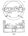
- Figure 1 is a top view in elevation of a schematic diagram of centrifugal apparatus embodying the automatic balancing concepts of the present invention;
- Figure 2 is a side-elevational view in cross-section, and partially broken away to show details of construction, of the apparatus shown in Figure 1, taken generally along the line 2-2 thereof;
- ?igure 3 is a partially schematic view of a portin of the apparatus shown in Figure 1, and showing a portion cf the centrifugal apparatus in an initial operational (rotational) condition; and
- Figure 4 is a view similar to Figure 3 but showing the portion of the apparatus in a fully rotational operational condition.
- Referring now in more detail to the drawings, Figures 1 and 2 illustrate preferred centrifugal apparatus embodying the concepts of the invention. The centrifuge generally shown includes a
plate member 10 which is mounted for rotation about anaxis 12. Theplate member 10 is preferably driven by a suitable drive means 14, which may be, for example, an electric motor operating at high speeds. Whileplate member 10 is illustrated in Figure 1 as a circular plate, it will be understood that its configuration is not critical to the practice of the invention. For example, it is equally possible to employ a centrifugal arm mounted for rotation about an axis. - Mounted on
plate member 10 is at least one sample processor card holding means 16 (although in the preferred embodiment shown, twoholding means 16 are illustrated). Theholding means 16 is adapted to receive a sample processor card, as described more fully in the foregoing copending applications. As is described in such copending applications, thecard holder 16 is preferably in the nature of a tray and is rotatably mounted relative to theplate member 10 on anaxis 18, specifically connected to means 20 (Figure 2) to rotate thecard holder 16. Since the particular means 20 to rotate the holding means 16 forms no part of the present invention, the details thereof have been omitted from the drawings for the sake of simplicity. - While the axis of
rotation 12 of theplate member 10 is illustrated in Figure 2 as being vertical, it will be understood by those skilled in the art that the orientation of theaxis 12 is not critical to the practice of the invention. Accordingly, the axis of rotation of theplate member 10, while preferably vertical, can also be horizontal, or inclined in any direction, since the effects of gravity on the sample processor card rotating with theplate member 10 are negligible. - In the preferred practice of the invention, the
card holder 16 can be rotated or indexed relative to theplate member 10 by themeans 20. In an especially preferred embodiment, the holding means 16 can be rotated or indexed substantially 90° relative to theplate member 10. However, as will be appreciated by those skilled in the art, theholding means 16 can be rotatable by an amount greater than 90°, up to and including a full 360°. The important feature is that thecard holder 16 be adapted to receive the sample processor card which is rotated relative to theplate member 10 so that the direction of the centrifugal force acting on the sample processor card can be altered to effect the necessary fluid-transport functions during the chemical testing operation. - For ease of description, shown in Figures 1 and 2 are a pair of
holding means 16 mounted symmetrically with respect to the axis ofrotation 12 of the plate member. 10. As will be appreciated by those skilled in the art, it is equally possible, and sometimes preferred, to equip theplate member 10 with only one or a greater number than two, ofholding means 16 which can be, and preferably are, symmetrically spaced about theplate member 10. - The automatic balancing device of the present invention includes a pair of
counterweights 22 and 22' which are capable of displacement along a radius of the axis ofrotation 12 of theplate member 10 toward and away from theholding means 16. Each of the'counterweights 22 and 22' is spring-biased by means of spring means 24 and 24', whereby the counterweight can be maintained in a stored position, illustrated by reference to the counterweight 22' in Figure 1. - Positioned adjacent to the
holding means 16 is a trigger means 26, pivotally mounted about a pivot point 28. The trigger means 26 has aportion 30 adapted to engage a corresponding engagement means 32 of thecounterweight 22. The trigger means includes acam surface 34 which is adapted to engage alateral surface 36 of asample processor card 38, when the latter is positioned in theholding means 16. - Considering the right-
hand holding means 16 in Figure 1, asample processor card 38, placed in theholding means 16, serves to pivot the trigger means 26' against the effect of a spring 40', so that the engaging portion 30' of the trigger means 26' engages the corresponding engaging means 32' of the counterweight 22'. Thus, as theplate member 10 is rotated, the counterweight 22' is prevented, by the engagement of the trigger means 26' with the counterweight 22', from being displaced toward theholding means 16. - When no sample processor card is positioned in the
holding means 16, as shown in the left-hand side of Figure 1, the trigger means 26 is biased by means of spring 40 away from engagement with the counterweight means 22. Thus, as theplate member 10 is rotated, thecounterweight 22 is displaced against the action of thespring 24 toward the left-hand holding means 16 shown in Figure 1. The displacement of thecounterweight 22 away from the axis ofrotation 12 of theplate member 10, as is appreciated by those skilled in the art, serves to counterbalance absence of the weight of thesample processor card 38 in the left-hand holding means 16. - Thus, a
sample processor card 38, by means of the trigger means 26', causes the counterweight 22' to remain in the stored position because of its presence, while the absence of a sample processor card in the left-hand holding means 16 allows thecounterweight 22 to be displaced. away from the axis ofrotation 12 of theplate member 10 to a balancing position, thereby to offset and counterbalance the absence of the sample processor card in the left-hand holding means 16 of Figure 1. - It will be well understood by those skilled in the art that other configurations and arrangements of the counterweight with respect to the sample processor card holding means are possible. For example, it is possible to employ one counterbalance system for each of a plurality of pairs of sample processor card holding means 16 upon the
plate member 10. In that way, a sample processor card would always be provided to the holding means 16 not equipped with the automatic balancing device, while the opposite holding means 16 would be provided with an automatic balancing mechanism to counterbalance the sample processor card when no sample processor card is used in such opposite holding means 16. - Referring now to Figures 3 and 4 of the drawings for a further explanation of the operation of a centrifuge incorporating the concepts of the present invention, in a preferred embodiment thereof, an enlarged view of the counterweight 22', trigger means 26' and
sample processor card 38 of Figures 1 and 2 is shown. In operation of the centrifuge and concommitant rotation of theplate member 10, as previously described, initial engagement of the trigger means 26' with the counterweight 22' is shown in Figure 3. In such initial engagement, agap 42 exists between anupper edge 32" of the engagement means 32' of the counterweight 22'; and portion 30' of the trigger means 26'; thegap 42 is present at the beginning of rotation of theplate member 10 when the centrifuge is initially placed in operation, as is the case when, for example, assays or chemical tests are being performed using the centrifuge. At this point in operation, the trigger means 26' is in contact with thecard 38 along itscam surface 34'. However, as shown in Figure 4, as theplate member 10 rotationally accelerates, the weight of the counterweight 22' bearing against the trigger means 26' further rotates the latter so that thegap 42 closes and the portion 30' of the trigger means 26' contacts the upper edge 32' of the engagement means 32'. The trigger means 26' therefore is no longer in contact along itscam surface 34' with thecard 38. Thus, thecard 38 can rotate freely relative to theplate member 10 without being hindered by the action of trigger means 26'. - It will be understood that various changes and modifications can be made in the specific details of construction, procedure and use of the invention as described herein, without departing from the spirit and scope of the invention, which is defined solely in the following claims.
Claims (10)
Applications Claiming Priority (2)
| Application Number | Priority Date | Filing Date | Title |
|---|---|---|---|
| US71351585A | 1985-03-19 | 1985-03-19 | |
| US713515 | 1985-03-19 |
Publications (3)
| Publication Number | Publication Date |
|---|---|
| EP0195321A2 true EP0195321A2 (en) | 1986-09-24 |
| EP0195321A3 EP0195321A3 (en) | 1986-12-10 |
| EP0195321B1 EP0195321B1 (en) | 1990-01-24 |
Family
ID=24866447
Family Applications (1)
| Application Number | Title | Priority Date | Filing Date |
|---|---|---|---|
| EP19860102975 Expired EP0195321B1 (en) | 1985-03-19 | 1986-03-06 | Automatic centrifugal balancing mechanism |
Country Status (4)
| Country | Link |
|---|---|
| EP (1) | EP0195321B1 (en) |
| JP (1) | JPS61216758A (en) |
| CA (1) | CA1259974A (en) |
| DE (1) | DE3668425D1 (en) |
Cited By (7)
| Publication number | Priority date | Publication date | Assignee | Title |
|---|---|---|---|---|
| EP0262060A2 (en) * | 1986-09-25 | 1988-03-30 | KIS PHOTO INDUSTRIE S.a.r.l. | Centrifugal arrangement for carrying out analyses |
| FR2605108A1 (en) * | 1986-09-25 | 1988-04-15 | Kis Photo Ind | Automatic device for performing analyses, in particular biological and medical analyses |
| FR2605104A1 (en) * | 1986-09-25 | 1988-04-15 | Kis Photo Ind | Device for dynamic balancing of a centrifuge apparatus |
| US5061381A (en) * | 1990-06-04 | 1991-10-29 | Abaxis, Inc. | Apparatus and method for separating cells from biological fluids |
| CN112044608A (en) * | 2020-10-12 | 2020-12-08 | 武汉成名仪器有限公司 | Balance locking device for rotor of laboratory centrifuge, centrifuge rotor and centrifuge |
| US11292014B2 (en) | 2015-04-05 | 2022-04-05 | Arteriocyte Medical Systems, Inc. | Centrifuge counterbalance with adjustable center of gravity and methods for using the same |
| CN112044608B (en) * | 2020-10-12 | 2024-04-16 | 武汉成名仪器有限公司 | Laboratory centrifuge rotor balance locking device, centrifuge rotor and centrifuge |
Citations (3)
| Publication number | Priority date | Publication date | Assignee | Title |
|---|---|---|---|---|
| US3762635A (en) * | 1971-04-14 | 1973-10-02 | Damon Corp | Apparatus for balancing a bucket centrifuge rotor |
| US3834613A (en) * | 1971-03-01 | 1974-09-10 | Int Equipment Co | Centrifuge rotor with sample holding means and means for balancing the same |
| EP0160901A2 (en) * | 1984-05-03 | 1985-11-13 | Abbott Laboratories | Centrifuge |
-
1986
- 1986-03-06 DE DE8686102975T patent/DE3668425D1/en not_active Expired - Fee Related
- 1986-03-06 EP EP19860102975 patent/EP0195321B1/en not_active Expired
- 1986-03-12 CA CA000503936A patent/CA1259974A/en not_active Expired
- 1986-03-19 JP JP5965186A patent/JPS61216758A/en active Pending
Patent Citations (3)
| Publication number | Priority date | Publication date | Assignee | Title |
|---|---|---|---|---|
| US3834613A (en) * | 1971-03-01 | 1974-09-10 | Int Equipment Co | Centrifuge rotor with sample holding means and means for balancing the same |
| US3762635A (en) * | 1971-04-14 | 1973-10-02 | Damon Corp | Apparatus for balancing a bucket centrifuge rotor |
| EP0160901A2 (en) * | 1984-05-03 | 1985-11-13 | Abbott Laboratories | Centrifuge |
Cited By (9)
| Publication number | Priority date | Publication date | Assignee | Title |
|---|---|---|---|---|
| EP0262060A2 (en) * | 1986-09-25 | 1988-03-30 | KIS PHOTO INDUSTRIE S.a.r.l. | Centrifugal arrangement for carrying out analyses |
| FR2605108A1 (en) * | 1986-09-25 | 1988-04-15 | Kis Photo Ind | Automatic device for performing analyses, in particular biological and medical analyses |
| FR2605104A1 (en) * | 1986-09-25 | 1988-04-15 | Kis Photo Ind | Device for dynamic balancing of a centrifuge apparatus |
| EP0262060A3 (en) * | 1986-09-25 | 1989-03-08 | Kis Photo Industrie (Societe Anonyme) | Centrifugal arrangement for carrying out analyses |
| US4865810A (en) * | 1986-09-25 | 1989-09-12 | Kis Photo Industrie | Centrifuge for performing medical analyses |
| US5061381A (en) * | 1990-06-04 | 1991-10-29 | Abaxis, Inc. | Apparatus and method for separating cells from biological fluids |
| US11292014B2 (en) | 2015-04-05 | 2022-04-05 | Arteriocyte Medical Systems, Inc. | Centrifuge counterbalance with adjustable center of gravity and methods for using the same |
| CN112044608A (en) * | 2020-10-12 | 2020-12-08 | 武汉成名仪器有限公司 | Balance locking device for rotor of laboratory centrifuge, centrifuge rotor and centrifuge |
| CN112044608B (en) * | 2020-10-12 | 2024-04-16 | 武汉成名仪器有限公司 | Laboratory centrifuge rotor balance locking device, centrifuge rotor and centrifuge |
Also Published As
| Publication number | Publication date |
|---|---|
| DE3668425D1 (en) | 1990-03-01 |
| EP0195321A3 (en) | 1986-12-10 |
| EP0195321B1 (en) | 1990-01-24 |
| JPS61216758A (en) | 1986-09-26 |
| CA1259974A (en) | 1989-09-26 |
Similar Documents
| Publication | Publication Date | Title |
|---|---|---|
| EP0853493B1 (en) | Method and apparatus for vortex mixing using centrifugal force | |
| KR880001695B1 (en) | Centrifuge | |
| JP3193443B2 (en) | Automatic analyzer | |
| US3722790A (en) | Sequential centrifugal treatment of liquid samples | |
| EP0567595B1 (en) | Self-balancing apparatus and method for a centrifuge device | |
| US5195825A (en) | Device for mixing at least one aqueous fluid substance | |
| US4671940A (en) | Automatic centrifugal balancing mechanism | |
| JPH0611512A (en) | Automatic apparatus for analyzing blood group | |
| EP0852515B1 (en) | Selectable angle centrifuges | |
| US7322926B2 (en) | Centrifugation device with swingable sample holder | |
| IL36602A (en) | A sample holder and transferring device for use in mixing and transferring liquids in a centrifugal field | |
| EP0195321B1 (en) | Automatic centrifugal balancing mechanism | |
| US4010892A (en) | Centrifuge equipment and analytical system using it | |
| US4835106A (en) | Rotor for processing liquids using movable capillary tubes | |
| CA2598807C (en) | Method of normalizing surface tension of a sample fluid | |
| CN215390019U (en) | Mixing and centrifuging device | |
| WO1993002348A1 (en) | Reagent handling system for automated clinical analyzer apparatus | |
| JPH0330820B2 (en) | ||
| CN210015113U (en) | Blood type card centrifugal device | |
| JPH0882629A (en) | Cover device of incubator | |
| JPH0330825B2 (en) | ||
| JPH04296654A (en) | Automatic analyzing device | |
| AU2014200240B2 (en) | Method of normalizing surface tension of a sample fluid |
Legal Events
| Date | Code | Title | Description |
|---|---|---|---|
| PUAI | Public reference made under article 153(3) epc to a published international application that has entered the european phase |
Free format text: ORIGINAL CODE: 0009012 |
|
| AK | Designated contracting states |
Kind code of ref document: A2 Designated state(s): BE DE FR IT |
|
| PUAL | Search report despatched |
Free format text: ORIGINAL CODE: 0009013 |
|
| AK | Designated contracting states |
Kind code of ref document: A3 Designated state(s): BE DE FR IT |
|
| 17P | Request for examination filed |
Effective date: 19870402 |
|
| 17Q | First examination report despatched |
Effective date: 19880725 |
|
| GRAA | (expected) grant |
Free format text: ORIGINAL CODE: 0009210 |
|
| AK | Designated contracting states |
Kind code of ref document: B1 Designated state(s): BE DE FR IT |
|
| REF | Corresponds to: |
Ref document number: 3668425 Country of ref document: DE Date of ref document: 19900301 |
|
| ET | Fr: translation filed | ||
| ITF | It: translation for a ep patent filed |
Owner name: MODIANO & ASSOCIATI S.R.L. |
|
| PLBE | No opposition filed within time limit |
Free format text: ORIGINAL CODE: 0009261 |
|
| STAA | Information on the status of an ep patent application or granted ep patent |
Free format text: STATUS: NO OPPOSITION FILED WITHIN TIME LIMIT |
|
| 26N | No opposition filed | ||
| PGFP | Annual fee paid to national office [announced via postgrant information from national office to epo] |
Ref country code: FR Payment date: 19910321 Year of fee payment: 6 |
|
| PGFP | Annual fee paid to national office [announced via postgrant information from national office to epo] |
Ref country code: DE Payment date: 19910327 Year of fee payment: 6 |
|
| ITTA | It: last paid annual fee | ||
| PGFP | Annual fee paid to national office [announced via postgrant information from national office to epo] |
Ref country code: BE Payment date: 19910626 Year of fee payment: 6 |
|
| PG25 | Lapsed in a contracting state [announced via postgrant information from national office to epo] |
Ref country code: BE Effective date: 19920331 |
|
| BERE | Be: lapsed |
Owner name: ABBOTT LABORATORIES Effective date: 19920331 |
|
| PG25 | Lapsed in a contracting state [announced via postgrant information from national office to epo] |
Ref country code: FR Effective date: 19921130 |
|
| PG25 | Lapsed in a contracting state [announced via postgrant information from national office to epo] |
Ref country code: DE Effective date: 19921201 |
|
| REG | Reference to a national code |
Ref country code: FR Ref legal event code: ST |
|
| PG25 | Lapsed in a contracting state [announced via postgrant information from national office to epo] |
Ref country code: IT Free format text: LAPSE BECAUSE OF NON-PAYMENT OF DUE FEES;WARNING: LAPSES OF ITALIAN PATENTS WITH EFFECTIVE DATE BEFORE 2007 MAY HAVE OCCURRED AT ANY TIME BEFORE 2007. THE CORRECT EFFECTIVE DATE MAY BE DIFFERENT FROM THE ONE RECORDED. Effective date: 20050306 |