EP0198297B1 - Device for direct driving of wheels - Google Patents
Device for direct driving of wheels Download PDFInfo
- Publication number
- EP0198297B1 EP0198297B1 EP86104277A EP86104277A EP0198297B1 EP 0198297 B1 EP0198297 B1 EP 0198297B1 EP 86104277 A EP86104277 A EP 86104277A EP 86104277 A EP86104277 A EP 86104277A EP 0198297 B1 EP0198297 B1 EP 0198297B1
- Authority
- EP
- European Patent Office
- Prior art keywords
- engine
- clutch
- wheel hub
- gear
- transmission
- Prior art date
- Legal status (The legal status is an assumption and is not a legal conclusion. Google has not performed a legal analysis and makes no representation as to the accuracy of the status listed.)
- Expired - Lifetime
Links
Images


Classifications
-
- B—PERFORMING OPERATIONS; TRANSPORTING
- B62—LAND VEHICLES FOR TRAVELLING OTHERWISE THAN ON RAILS
- B62M—RIDER PROPULSION OF WHEELED VEHICLES OR SLEDGES; POWERED PROPULSION OF SLEDGES OR SINGLE-TRACK CYCLES; TRANSMISSIONS SPECIALLY ADAPTED FOR SUCH VEHICLES
- B62M6/00—Rider propulsion of wheeled vehicles with additional source of power, e.g. combustion engine or electric motor
- B62M6/10—Rider propelled cycles with auxiliary combustion engine
- B62M6/25—Rider propelled cycles with auxiliary combustion engine power-driven at axle parts
-
- B—PERFORMING OPERATIONS; TRANSPORTING
- B62—LAND VEHICLES FOR TRAVELLING OTHERWISE THAN ON RAILS
- B62M—RIDER PROPULSION OF WHEELED VEHICLES OR SLEDGES; POWERED PROPULSION OF SLEDGES OR SINGLE-TRACK CYCLES; TRANSMISSIONS SPECIALLY ADAPTED FOR SUCH VEHICLES
- B62M6/00—Rider propulsion of wheeled vehicles with additional source of power, e.g. combustion engine or electric motor
- B62M6/10—Rider propelled cycles with auxiliary combustion engine
-
- B—PERFORMING OPERATIONS; TRANSPORTING
- B62—LAND VEHICLES FOR TRAVELLING OTHERWISE THAN ON RAILS
- B62M—RIDER PROPULSION OF WHEELED VEHICLES OR SLEDGES; POWERED PROPULSION OF SLEDGES OR SINGLE-TRACK CYCLES; TRANSMISSIONS SPECIALLY ADAPTED FOR SUCH VEHICLES
- B62M7/00—Motorcycles characterised by position of motor or engine
- B62M7/12—Motorcycles characterised by position of motor or engine with the engine beside or within the driven wheel
Definitions
- This invention relates to a device according to the preamble of claim 1.
- a device has been disclosed by US-A 1 394 516 or GB-A 526 193.
- an engine and a transmission are positioned inside a wheel hub such as to reduce the axial and radial size and the weight of the hub so as to make the device suitable for lightweight vehicles, expecially for common bikes which cannot only driven by the engine but also by manpower. If the bike is driven by manpower in case the engine is not used, the load shall be as small as possible. If the engine drive system is used it shall be possible to support the engine drive mode by manpower in case the engine suffers an overload at a situation when the slope of the road is excessively big. It should also be possible to convert conveniently between the man-drive mode and the engine-drive mode or a combined drive mode wherein both modes are used simultaneously.
- the device according to US-A 1 394, 516 provides only an engine-drive mode.
- the transmission comprises a clutch means in order to disconnect a driving shaft from another part of the transmission when starting the engine by means of a crank which can be coupled with the driving shaft.
- the device according to GB-A 526 193 provides besides an engine-drive mode also a pedal-drive mode and a simultaneous operation of both drives.
- To disconnect the engine drive it is necessary to disengage by an actuator a clutch which is mounted in a lay-shaft of the transmission. Therefore, even if the clutch is disengaged some parts of the transmission are still connected with the hub and have to be driven by manpower.
- the clutch cannot be operated automatically but only by an actuator.
- the device described in US-A 4 132 281 comprises an engine with its crank shaft arranged coaxially to the wheel and the longitudinal symmetrical plane of the engine body being coincide with the symmetrical plane of the wheel.
- the need of maintaining a certain piston stroke forces the hub to be radially oversized.
- Installing the reduction drive mechanism, magneto and cooling fan at the outside of the engine body makes also the whole device to be axially oversized as well as overweighted. Because the support bearing of the hub is offset from the central symmetrical plane of the wheel the load of the bearing is increased and stability of the wheel decreased.
- a friction clutch of the automatic centrifugal type which connects the engine with the transmission only if the engine is running and besides that a clutch which can be actuated by a handle is provided in the transmission to separate part of the gears of the transmission from the hub when riding the motor-cycle by manpower also in this case part of the gears of the ⁇ transmission are always connected with the hub and therefore, have to be driven too when the engine is stopped and disengaged from the hub.
- the device according to the invention comprises a first and a second clutch means to automatically connect the transmission to the engine and to the wheel hub, respectively during operation of the engine and to automatically disconnect the transmission from the engine and from the wheel hub respectively when the engine is stopped.
- the first clutch means is a centrifugal frictional clutch and the second clutch means an overrunning clutch.
- a starting mechanism for controlably transmitting a wheel hub rotation to the engine crank shaft.
- This starting mechanism comprises also clutch means in order to attain a connection between the wheel hub and the engine crank shaft when the wheel hub is rotated by manpower in case of starting the engine. After start of the engine the starting mechanism has to be disconnected. These operations are effected preferably by a gear clutch and a further overrunning clutch.
- the device for direct-driving of wheels proposed by the present invention can be adapted for various kinds of light-weight vehicles, in particular for motorbikes or motorcycles.
- the device comprises engine transmission units, a fixed wheel axle, a wheel hub and a set of an actuating mechanism, wherein the engine and the parts of the transmission units are all arranged inside the hub located at the center of the wheel.
- the said engine mounted in the hub is a two-stroke gasoline engine, the longitudinal axis of the cylinder body therof lies in an orthogonal plane of the wheel axle, or perpendicularly intersects with the axial line of the wheel; the main journals of the crankshaft are offset from an parallel with the wheel axle.
- the crankshaft has one end thereof mounted with a magneto rotor and another end thereof connected with the transmission units via a clutch; the inner axial distance between said magneto rotor and rotatable members of the clutch is smaller than the diameter of the cylinder bore.
- the reciprocating piston in the engine cylinder has a recess on its top surface, and a pair of lugs extending from the inner side of the top section forms piston seatings for mounting the piston pin therein.
- the piston skirt portion has a thin-wall structure, the parts of which near the axial line of the piston pin are cut off to form openings.
- the vertical distance from the lowest point of the skirt to the axial line of the crankshaft is smaller than the gyro radius of said magneto and clutch means when the piston is at the bottom dead center.
- an overrunning clutch is used at the last stage of the transmission units to transmit the propulsion power, so that it is possible to rotate the wheel in both forward and backward directions easily when the engine stops. It is also possible to add the manpower to the wheel in case the engine suffers an overload at situation such as when the slope of the road is excessively big.
- the start system in the device transmits the rotation of the hub to the engine crankshaft through the meshing of a gear clutch in the transmission units.
- the gear clutch turns to get inactive, and the driving force is transmitted by means of the friction of flying-weights of a centrifugal friction clutch and the overrunning clutch, with the result of avoiding the damage of the teeth of the gear clutch.
- the relative sliding between the flying-weights and the outer dish of the centrifugal friction clutch, and between the driving and driven members of the overrunning clutch can provide protection to the engine and transmission units in case of overload.
- the impulse-proof type of the gear drive mechnism for example the spiral tooth gear, arc tooth gear, or involute herringbone tooth gear drive mechnism, may be used in the device to raise the stability and smoothness of power transmission, wherein the rim of at least a big gear is separated from its hub portion, with an elastic ring being fitted in between, in order to reduce the impulsion and shock when the engine is being started.
- a brake means composed of brake hoof blocks and the wall of said wheel hub is provided in the device for the purpose of braking the wheel quickly and reliably.
- Two vertical side walls of the wheel hub are supported on the wheel axle shaft and on a boss ring axially protruding from the engine body fixed to the said shaft via bearings respectively, to assure a better load condition of the bearings and a stable and reliable support of the wheel.
- the said transmission units are disposed in a sealed box located inside the said hub, and can be lubricated with liquid lubricant, one side of the sealed box is fixed to the crankcase of the engine and the other side thereof is supported on the axially extending portion of a internal gear via a bearing, with sealing rings being provided thereto.
- Channels are provided in the said boss ring to allow the insertion of oil inlet pipes, various actuating means and exhaust pipes, Besides, there are provided some openings on the wall of the wheel hub of the device to facilitate ventilation and maintenance. It is also appropriate to provide the hub wall with blades for introducing cooling air.
- the conversion between the manpower drive mode and the engine drive mode, the speed regulation of the engine drive mode, are integrally controlled by handles.
- This embodiment according to the present invention (as shown in Fig. 2) is a device comprising engine and drive units, which is adapted mainly to bicy- des or motor cycles.
- the engine in the said device is started through such a process to be described as follows:
- the propulsion power of the engine is transmitted through the drive units to the wheel by the process to be described as follows:
- the method to operate a bicycle equiped with a drive device according to the present invention may be as follows:
Description
- This invention relates to a device according to the preamble of claim 1.
- A device according to this kind has been disclosed by US-A 1 394 516 or GB-A 526 193. In such a device an engine and a transmission are positioned inside a wheel hub such as to reduce the axial and radial size and the weight of the hub so as to make the device suitable for lightweight vehicles, expecially for common bikes which cannot only driven by the engine but also by manpower. If the bike is driven by manpower in case the engine is not used, the load shall be as small as possible. If the engine drive system is used it shall be possible to support the engine drive mode by manpower in case the engine suffers an overload at a situation when the slope of the road is excessively big. It should also be possible to convert conveniently between the man-drive mode and the engine-drive mode or a combined drive mode wherein both modes are used simultaneously.
- The device according to US-A 1 394, 516 provides only an engine-drive mode. The transmission comprises a clutch means in order to disconnect a driving shaft from another part of the transmission when starting the engine by means of a crank which can be coupled with the driving shaft.
- The device according to GB-A 526 193 provides besides an engine-drive mode also a pedal-drive mode and a simultaneous operation of both drives. To disconnect the engine drive it is necessary to disengage by an actuator a clutch which is mounted in a lay-shaft of the transmission. Therefore, even if the clutch is disengaged some parts of the transmission are still connected with the hub and have to be driven by manpower. The clutch cannot be operated automatically but only by an actuator.
- The device described in US-A 4 132 281 comprises an engine with its crank shaft arranged coaxially to the wheel and the longitudinal symmetrical plane of the engine body being coincide with the symmetrical plane of the wheel. The need of maintaining a certain piston stroke forces the hub to be radially oversized. Installing the reduction drive mechanism, magneto and cooling fan at the outside of the engine body makes also the whole device to be axially oversized as well as overweighted. Because the support bearing of the hub is offset from the central symmetrical plane of the wheel the load of the bearing is increased and stability of the wheel decreased. Although in this case a friction clutch of the automatic centrifugal type is provided which connects the engine with the transmission only if the engine is running and besides that a clutch which can be actuated by a handle is provided in the transmission to separate part of the gears of the transmission from the hub when riding the motor-cycle by manpower also in this case part of the gears of the ` transmission are always connected with the hub and therefore, have to be driven too when the engine is stopped and disengaged from the hub.
- In order to solve the problems mentioned above it is an object of the invention to disengage the reduction drive system completely from the hub when the engine is stopped so as to permit an easy riding by manpower. Still further it is an object to ensure a simple, safe and convenient conversion between the man-drive mode and engine-drive mode, as well as an incorporation of the two.
- The invention is characterized by the features of claim 1. Further features of the invention are described in the subclaims.
- The device according to the invention comprises a first and a second clutch means to automatically connect the transmission to the engine and to the wheel hub, respectively during operation of the engine and to automatically disconnect the transmission from the engine and from the wheel hub respectively when the engine is stopped. Preferably, the first clutch means is a centrifugal frictional clutch and the second clutch means an overrunning clutch.
- For starting the engine a starting mechanism for controlably transmitting a wheel hub rotation to the engine crank shaft is provided. This starting mechanism comprises also clutch means in order to attain a connection between the wheel hub and the engine crank shaft when the wheel hub is rotated by manpower in case of starting the engine. After start of the engine the starting mechanism has to be disconnected. These operations are effected preferably by a gear clutch and a further overrunning clutch.
- The device for direct-driving of wheels proposed by the present invention can be adapted for various kinds of light-weight vehicles, in particular for motorbikes or motorcycles. The device comprises engine transmission units, a fixed wheel axle, a wheel hub and a set of an actuating mechanism, wherein the engine and the parts of the transmission units are all arranged inside the hub located at the center of the wheel.
- The said engine mounted in the hub is a two-stroke gasoline engine, the longitudinal axis of the cylinder body therof lies in an orthogonal plane of the wheel axle, or perpendicularly intersects with the axial line of the wheel; the main journals of the crankshaft are offset from an parallel with the wheel axle. The crankshaft has one end thereof mounted with a magneto rotor and another end thereof connected with the transmission units via a clutch; the inner axial distance between said magneto rotor and rotatable members of the clutch is smaller than the diameter of the cylinder bore. The reciprocating piston in the engine cylinder has a recess on its top surface, and a pair of lugs extending from the inner side of the top section forms piston seatings for mounting the piston pin therein. The piston skirt portion has a thin-wall structure, the parts of which near the axial line of the piston pin are cut off to form openings. The vertical distance from the lowest point of the skirt to the axial line of the crankshaft is smaller than the gyro radius of said magneto and clutch means when the piston is at the bottom dead center.
- In the device according to the present invention an overrunning clutch is used at the last stage of the transmission units to transmit the propulsion power, so that it is possible to rotate the wheel in both forward and backward directions easily when the engine stops. It is also possible to add the manpower to the wheel in case the engine suffers an overload at situation such as when the slope of the road is excessively big.
- The start system in the device according to the present invention transmits the rotation of the hub to the engine crankshaft through the meshing of a gear clutch in the transmission units. After the engine has been started, the gear clutch turns to get inactive, and the driving force is transmitted by means of the friction of flying-weights of a centrifugal friction clutch and the overrunning clutch, with the result of avoiding the damage of the teeth of the gear clutch. The relative sliding between the flying-weights and the outer dish of the centrifugal friction clutch, and between the driving and driven members of the overrunning clutch can provide protection to the engine and transmission units in case of overload.
- The impulse-proof type of the gear drive mechnism, for example the spiral tooth gear, arc tooth gear, or involute herringbone tooth gear drive mechnism, may be used in the device to raise the stability and smoothness of power transmission, wherein the rim of at least a big gear is separated from its hub portion, with an elastic ring being fitted in between, in order to reduce the impulsion and shock when the engine is being started.
- A brake means composed of brake hoof blocks and the wall of said wheel hub is provided in the device for the purpose of braking the wheel quickly and reliably.
- Two vertical side walls of the wheel hub are supported on the wheel axle shaft and on a boss ring axially protruding from the engine body fixed to the said shaft via bearings respectively, to assure a better load condition of the bearings and a stable and reliable support of the wheel.
- The said transmission units are disposed in a sealed box located inside the said hub, and can be lubricated with liquid lubricant, one side of the sealed box is fixed to the crankcase of the engine and the other side thereof is supported on the axially extending portion of a internal gear via a bearing, with sealing rings being provided thereto.
- Channels are provided in the said boss ring to allow the insertion of oil inlet pipes, various actuating means and exhaust pipes, Besides, there are provided some openings on the wall of the wheel hub of the device to facilitate ventilation and maintenance. It is also appropriate to provide the hub wall with blades for introducing cooling air.
- The conversion between the manpower drive mode and the engine drive mode, the speed regulation of the engine drive mode, are integrally controlled by handles.
- For a better understanding of the nature and characteristics of the present invention, we are going to describe the embodiments according to the present invention in detail by way of the following accompanying drawings in which:
- Fig. 1 is an outline view of the drive device of the prior art;
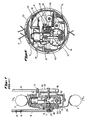
- Fig. 2 is a schematic drawing of an embodiment of the present invention;
- Fig. 3 is a cross section view of the overrunning clutch located on the start gear of an embodiment of the present invention;
- Fig. 4 is an elevational view of the centrifugal clutch comprising a friction flying-weight and outer dish of an embodiment of the present invention;
- Fig. 5 is an elevational view of the overrunning clutch located on the internal gear of an embodiment of the present invention;
- Fig. 6 is a schematic view showing the arrangement of the engine and the transmission units in the wheel hub;
- Fig. 7 is a diagrammatic sketch of the brake of an embodiment of the present invention.
- This embodiment according to the present invention (as shown in Fig. 2) is a device comprising engine and drive units, which is adapted mainly to bicy- des or motor cycles. The engine in the said device is started through such a process to be described as follows:
- While rolling the vehicle wheel forward by manpower, lift the hand shank 1 on the handle bar of the vehicle in the direction shown by the arrow A in Fig. 2, pulling the
lever 4 into motion through awire 3 connected between the shank 1 and one end of thelever 4, the other end of thelever 4 being connected to the right end of apush rod 5, thus moving thepush rod 5 in the direction shown by the arrow B in Fig. 2, so making theright part 9 of the tooth clutch to move leftward with the help of apin 6 disposed at the radial direction of thepush rod 5, thus causing theleft part 8 of the gear clutch to mesh with theright part 9 thereof, saidright part 9 being connected with the wheel hub via aspline 12, while theleft part 8 of the gear clutch being fixed on theinternal gear 23 which engages with thestart gear 25 which is mounted on thecrankshaft 30 of theengine 15 with anoverrunning clutch 29 being disposed in between (as shown in Fig. 3), thus, the rotational movement of the wheel hub being finally transmitted to the crankshaft. Provide the engine with electricity and fuel supply in time. So the engine is started. - The propulsion power of the engine is transmitted through the drive units to the wheel by the process to be described as follows:
- After the start of the
engine 15, thecrankshaft 30 brings thecentral portion 7 of the centrifugal friction clutch mounted thereon into fast rotation, causing the flying-weight 21 of the clutch to get into contact with the outer dish 22 (see Fig. 4), the friction therebetween causes the rotational movement of thedish 22, and consequently of thesmall gear 14 fixed therewith,gear 14 engages with theduplex gear 13 which transmits the rotational movement to theinternal gear 23 by means of anidler 24. The disc portion of theinternal gear 23 has an axially extending central sleeve, the outer wall of which is provided with a wedge ring 27 (as shown in Fig. 5). By means ofrollers 28, thewedge ring 27 rotating in the direction shown by the arrow C in Fig. 5 transmits the propulsion to thehub 10. Since the engine body is firmly fixed to theframe 38 through both ends of theaxle shaft 37, which prevents the drive device from being counter rotated, thus the wheel hub rotates forwardly under the propulsion. It is recommended to adopt spiral gears or herringbone gears in the above said drive units to get a stable and smooth power transmission. - It is evident from the trilateral relation of the
wedge ring 27,pin roller 28 andhub 10 that the rotation of thehub 10 alone in the C direction can hardly cause the rotation of thewedge ring 27, therefore there are hardly any interferences between the engine drive mode and the manpower drive mode. And in the case that the engine suffers a temporary overload, the manpower drive may be added to the wheel by means of pedals, chain and sprockets. - Besides, when an excessive overload occurs (such as encountering sudden obstacle on the road surface, travelling up-hill along a road of an excessively big slope, etc.) the relative sliding between the flying-
weight 21 and theouter dish 22 as well as between therollers 28 and thehub 10 provide overload protection to the engine. - The method to operate a bicycle equiped with a drive device according to the present invention may be as follows:
- 1. Before starting the engine, rotate the vehicle wheel by any suitable ways (such as pushing, or riding the well-known pedal, chain and sprocket assembly). Switch on the electrical circuit of the engine, pull the hand shank 1 located on the left handle bar in the direction shown by the arrow A in Fig. 2, rotate the handle 2 located on the right handle bar (i.e. opening the throttle valve). As a result, the engine being started. Rotate the handle 2 further to regulate the required fuel supply, then ride the vehicle forward.
- 2. The stop process of the vehicle mentioned above is as follows: First, cut off the electrical power by pressing down the
button 16 to stop engine, then stop the vehicle after slipping for a certain distance; or hold the brake handle 17 (the same as on the common bikes or motorcycles) immediately after pressing down the .button 16, to actuate the brake means composed of thebrake cam 18, thesupport shaft 19 fixed in thebox 31, the brake hoof blocks 20 and the wall of the wheel hub (see Fig. 7), so as to make the two brake hoof blocks 20 expand outwardly in thehub 10, causing a sudden stop.
Claims (14)
Applications Claiming Priority (2)
| Application Number | Priority Date | Filing Date | Title |
|---|---|---|---|
| CN85101503 | 1985-04-01 | ||
| CN85101503A CN85101503B (en) | 1985-04-01 | 1985-04-01 | Direct drive unit of vehicle wheel |
Publications (3)
| Publication Number | Publication Date |
|---|---|
| EP0198297A2 EP0198297A2 (en) | 1986-10-22 |
| EP0198297A3 EP0198297A3 (en) | 1987-05-27 |
| EP0198297B1 true EP0198297B1 (en) | 1990-08-16 |
Family
ID=4791878
Family Applications (1)
| Application Number | Title | Priority Date | Filing Date |
|---|---|---|---|
| EP86104277A Expired - Lifetime EP0198297B1 (en) | 1985-04-01 | 1986-03-27 | Device for direct driving of wheels |
Country Status (6)
| Country | Link |
|---|---|
| US (1) | US4721177A (en) |
| EP (1) | EP0198297B1 (en) |
| JP (1) | JPS62295721A (en) |
| CN (2) | CN85101503B (en) |
| AU (1) | AU578525B2 (en) |
| DE (1) | DE3673441D1 (en) |
Families Citing this family (42)
| Publication number | Priority date | Publication date | Assignee | Title |
|---|---|---|---|---|
| GB8629897D0 (en) * | 1986-12-15 | 1987-01-28 | Hydro Spartan Ltd | Wheel drive arrangement |
| US5937962A (en) * | 1995-08-08 | 1999-08-17 | Yamaha Hatsudoki Kabushiki Kaisha | Bicycle with assist engine |
| TW451881U (en) * | 1995-08-30 | 2001-08-21 | Sanyo Electric Co | Electric vehicle |
| USRE37583E1 (en) * | 1997-02-20 | 2002-03-19 | Currie Technologies, Incorporated | Precision direct drive mechanism for a power assist apparatus for a bicycle |
| US5934401A (en) * | 1997-02-20 | 1999-08-10 | Currie Technologies, Incorporated | Precision direct drive mechanism for a power assist apparatus for a bicycle |
| US6199652B1 (en) | 1997-12-11 | 2001-03-13 | Vectrix Corporation | Vehicle drive wheel assembly |
| US6199651B1 (en) | 1997-12-11 | 2001-03-13 | Vectrix Corporation | Vehicle drive wheel assembly |
| US6296072B1 (en) | 1999-01-20 | 2001-10-02 | Opti-Bike Llc | Electric bicycle and methods |
| EP1514025A4 (en) * | 2002-05-15 | 2007-10-31 | Stephen B Katsaros | Hub motor formed in a wheel and a method associated therewith |
| FR2842147A1 (en) * | 2002-07-15 | 2004-01-16 | Conception & Dev Michelin Sa | DRIVE CHAIN HAVING A GEAR CHANGE MECHANISM INTEGRATED IN A WHEEL |
| US7464775B2 (en) * | 2003-02-21 | 2008-12-16 | Lockheed Martin Corporation | Payload module for mobility assist |
| US20040232632A1 (en) * | 2003-02-21 | 2004-11-25 | Beck Michael S. | System and method for dynamically controlling the stability of an articulated vehicle |
| US7150340B2 (en) * | 2003-02-21 | 2006-12-19 | Lockheed Martin Corporation | Hub drive and method of using same |
| US7261176B2 (en) * | 2003-02-21 | 2007-08-28 | Lockheed Martin Corporation | Articulated vehicle suspension system shoulder joint |
| US8839891B2 (en) | 2003-02-21 | 2014-09-23 | Lockheed Martin Corporation | Multi-mode skid steering |
| US20040163869A1 (en) * | 2003-02-21 | 2004-08-26 | Chun Wendell H. | Articulated vehicle suspension system shoulder joint |
| US20050023052A1 (en) * | 2003-02-21 | 2005-02-03 | Beck Michael S. | Vehicle having an articulated suspension and method of using same |
| JP4263587B2 (en) * | 2003-12-08 | 2009-05-13 | 本田技研工業株式会社 | One-way clutch device and motorcycle using the same |
| CN101044054A (en) * | 2004-08-25 | 2007-09-26 | S·B·卡察罗斯 | Hub motor formed in a wheel and associated methods |
| US7156196B2 (en) * | 2004-11-12 | 2007-01-02 | Stephen Basil Katsaros | Hub motor formed in a wheel |
| EP1733962A3 (en) * | 2005-06-17 | 2007-09-05 | Shimano Inc. | Bicycle wheel driving device |
| JP4073929B2 (en) * | 2005-06-17 | 2008-04-09 | 株式会社シマノ | Bicycle wheel drive device |
| CN1880160B (en) * | 2005-06-17 | 2010-04-28 | 株式会社岛野 | Mounting and connection parts for roller type brake |
| US8096103B1 (en) | 2006-08-03 | 2012-01-17 | Radius X, LLC | External combustion engine with a general wheel rotation power motor |
| US20080129107A1 (en) * | 2006-12-01 | 2008-06-05 | Keith Hodgson | Motor-Bearing Wheel Hub |
| FR2918034B3 (en) | 2007-06-26 | 2011-10-28 | Yvan Philippe Gilles Pesenti | THERMAL ASSISTANCE FOR BICYCLES. |
| CN201367091Y (en) * | 2009-01-16 | 2009-12-23 | 彭伟乐 | Front-driven chainless gear transmission bicycle |
| US9027681B2 (en) * | 2009-12-04 | 2015-05-12 | Massachusetts Institute Of Technology | Hybrid sensor-enabled electric wheel and associated systems, multi-hub wheel spoking systems, and methods of manufacturing and installing wheel spokes |
| CN101767529B (en) * | 2010-03-25 | 2013-02-13 | 台州市黄岩华阳机电科技有限公司 | Clutch type output mechanism of electrically-propelled vehicle shifting driving hub |
| JP5149938B2 (en) * | 2010-06-11 | 2013-02-20 | 株式会社シマノ | Bicycle hub with built-in motor |
| US10005317B2 (en) | 2014-04-04 | 2018-06-26 | Superpedestrian, Inc. | Devices and methods of thermal management for a motorized wheel |
| WO2015154046A1 (en) | 2014-04-04 | 2015-10-08 | Superpedestrian, Inc. | Systems, methods, and devices for the operation of electrically motorized vehicles |
| US10308065B2 (en) | 2014-04-04 | 2019-06-04 | Superpedestrian, Inc. | Devices and methods for connecting a spoke to a hub |
| EP3224056A4 (en) | 2014-11-24 | 2018-08-22 | Superpedestrian, Inc. | Devices and methods of a motorized wheel |
| CN104494774B (en) * | 2015-01-28 | 2016-10-05 | 朱幕松 | Remote control gear clutch Dual Drive high-speed brushless big hub motor |
| CN106050949B (en) * | 2016-07-25 | 2018-11-23 | 西安科技大学 | A kind of flexible torque increment shaft coupling for soft start |
| CN106985963B (en) * | 2017-05-11 | 2022-06-07 | 张家港川梭车业有限公司 | Single-wheel drive three-gear speed change device |
| RU2666622C1 (en) * | 2017-05-22 | 2018-09-11 | Владимир Григорьевич Гончаров | Motorized bicycle transmission (variants) |
| KR102626712B1 (en) * | 2018-12-27 | 2024-01-17 | 현대트랜시스 주식회사 | In-wheel motor powertrain |
| JP2020192951A (en) * | 2019-05-30 | 2020-12-03 | ヤマハ発動機株式会社 | In-wheel motor unit and electric vehicle |
| NO345745B1 (en) * | 2019-12-05 | 2021-07-12 | Ca Tech Systems As | Breathing mechanical power transmission and a pedally propelled vehicle with such power transmission |
| CN111016640B (en) * | 2019-12-31 | 2022-03-01 | 西南大学 | Compact central driving type self-adaptive electric driving assembly with ultra-large load |
Family Cites Families (12)
| Publication number | Priority date | Publication date | Assignee | Title |
|---|---|---|---|---|
| US904721A (en) * | 1907-04-01 | 1908-11-24 | Jules Emile Perillard | Motor-wheel for cycles. |
| US1247752A (en) * | 1916-10-24 | 1917-11-27 | Power Wheel Mfg Company | Motor-wheel for cycles. |
| US1394516A (en) * | 1920-02-24 | 1921-10-18 | Burlat Antoine | Motorcycle |
| DE706520C (en) * | 1938-03-10 | 1941-05-28 | Auto Union A G | Motor bike with drive block built into the rear wheel |
| US2253408A (en) * | 1939-06-28 | 1941-08-19 | Ernest M Watkins | Motor driven vehicle |
| FR981787A (en) * | 1946-11-12 | 1951-05-30 | Drive wheel for bicycles, tricycles and similar vehicles | |
| US2588889A (en) * | 1948-07-22 | 1952-03-11 | Adrienne M Sherwood | Motor wheel and mounting strut |
| US3626815A (en) * | 1970-05-25 | 1971-12-14 | American Motors Corp | Piston |
| DE2253868B2 (en) * | 1972-11-03 | 1980-11-20 | M.A.N. Maschinenfabrik Augsburg-Nuernberg Ag, 8500 Nuernberg | One-piece cast iron piston connected to a connecting rod |
| US4091887A (en) * | 1976-12-15 | 1978-05-30 | Honda Giken Kogyo Kabushiki Kaisha | Power unit for a motor cycle |
| DE3024891A1 (en) * | 1980-07-01 | 1982-02-11 | Karl Schmidt Gmbh, 7107 Neckarsulm | LIGHT METAL CONTROL PISTON FOR INTERNAL COMBUSTION ENGINES |
| JPS6035681A (en) * | 1983-08-08 | 1985-02-23 | 本田技研工業株式会社 | Transmission device in car |
-
1985
- 1985-04-01 CN CN85101503A patent/CN85101503B/en not_active Expired
-
1986
- 1986-03-26 US US06/844,176 patent/US4721177A/en not_active Expired - Fee Related
- 1986-03-27 EP EP86104277A patent/EP0198297B1/en not_active Expired - Lifetime
- 1986-03-27 DE DE8686104277T patent/DE3673441D1/en not_active Expired - Lifetime
- 1986-03-27 AU AU55317/86A patent/AU578525B2/en not_active Ceased
- 1986-03-31 JP JP61071386A patent/JPS62295721A/en active Pending
- 1986-04-25 CN CN86102809.0A patent/CN1003990B/en not_active Expired
Also Published As
| Publication number | Publication date |
|---|---|
| DE3673441D1 (en) | 1990-09-20 |
| EP0198297A3 (en) | 1987-05-27 |
| EP0198297A2 (en) | 1986-10-22 |
| CN86102809A (en) | 1987-12-16 |
| US4721177A (en) | 1988-01-26 |
| JPS62295721A (en) | 1987-12-23 |
| CN85101503A (en) | 1987-10-07 |
| CN85101503B (en) | 1987-12-23 |
| AU5531786A (en) | 1986-10-09 |
| CN1003990B (en) | 1989-04-26 |
| AU578525B2 (en) | 1988-10-27 |
Similar Documents
| Publication | Publication Date | Title |
|---|---|---|
| EP0198297B1 (en) | Device for direct driving of wheels | |
| US7770682B2 (en) | Power assist system and method for a vehicle | |
| EP1770307B1 (en) | V-belt type continuously variable transmission for small-sized vehicle and saddle-riding type vehicle | |
| JP4270459B2 (en) | Control device for continuously variable transmission mechanism | |
| EP0714801B1 (en) | Belt-drive variable speed transmission | |
| JPH0346697B2 (en) | ||
| EP0700826B1 (en) | Method of controlling assisting motor for bicycle | |
| JPH08175477A (en) | Power switching device of engine and motor of motor cycle | |
| CA2376787A1 (en) | Motorization of a bicycle with a simple replacement of the bottom bracket | |
| JP3140538B2 (en) | Component Arrangement Structure of Power Transmission Device in Saddle-ride Type Vehicle | |
| EP0145431A2 (en) | Vehicle drive | |
| RU2666622C1 (en) | Motorized bicycle transmission (variants) | |
| JP2022539973A (en) | bicycle electric gear motor assembly | |
| CN1087247C (en) | Bicycle with auxiliary engine | |
| JP3582288B2 (en) | Motorcycle tricycle clutch device | |
| EP4289714A1 (en) | Vehicle, in particular scooter | |
| CN110573418B (en) | Transmission system for two-wheeled vehicle | |
| JPS5923673Y2 (en) | Bicycle drive device with auxiliary engine | |
| CN2170265Y (en) | Device for directly driving wheels | |
| CN2199930Y (en) | Rear-wheel directly driven type asistor for minicar | |
| CN2138618Y (en) | Rear wheel force aiding device of bicycle | |
| JPH05213263A (en) | Power transmission device for motorcycle | |
| JP3313387B2 (en) | Vehicle body component arrangement structure | |
| CN1105323A (en) | Mini-vehicle assistor with rear wheel driven directly | |
| CN117545683A (en) | Power assisted drive assembly |
Legal Events
| Date | Code | Title | Description |
|---|---|---|---|
| PUAI | Public reference made under article 153(3) epc to a published international application that has entered the european phase |
Free format text: ORIGINAL CODE: 0009012 |
|
| AK | Designated contracting states |
Kind code of ref document: A2 Designated state(s): CH DE FR GB IT LI |
|
| PUAL | Search report despatched |
Free format text: ORIGINAL CODE: 0009013 |
|
| AK | Designated contracting states |
Kind code of ref document: A3 Designated state(s): CH DE FR GB IT LI |
|
| 17P | Request for examination filed |
Effective date: 19871119 |
|
| 17Q | First examination report despatched |
Effective date: 19880316 |
|
| GRAA | (expected) grant |
Free format text: ORIGINAL CODE: 0009210 |
|
| AK | Designated contracting states |
Kind code of ref document: B1 Designated state(s): CH DE FR GB IT LI |
|
| REF | Corresponds to: |
Ref document number: 3673441 Country of ref document: DE Date of ref document: 19900920 |
|
| ET | Fr: translation filed | ||
| ITF | It: translation for a ep patent filed |
Owner name: ING. ZINI MARANESI & C. S.R.L. |
|
| ITTA | It: last paid annual fee | ||
| PLBE | No opposition filed within time limit |
Free format text: ORIGINAL CODE: 0009261 |
|
| STAA | Information on the status of an ep patent application or granted ep patent |
Free format text: STATUS: NO OPPOSITION FILED WITHIN TIME LIMIT |
|
| 26N | No opposition filed | ||
| PGFP | Annual fee paid to national office [announced via postgrant information from national office to epo] |
Ref country code: FR Payment date: 19940328 Year of fee payment: 9 Ref country code: DE Payment date: 19940328 Year of fee payment: 9 |
|
| PGFP | Annual fee paid to national office [announced via postgrant information from national office to epo] |
Ref country code: CH Payment date: 19940406 Year of fee payment: 9 |
|
| PG25 | Lapsed in a contracting state [announced via postgrant information from national office to epo] |
Ref country code: LI Effective date: 19950331 Ref country code: CH Effective date: 19950331 |
|
| PG25 | Lapsed in a contracting state [announced via postgrant information from national office to epo] |
Ref country code: FR Free format text: LAPSE BECAUSE OF NON-PAYMENT OF DUE FEES Effective date: 19951130 |
|
| REG | Reference to a national code |
Ref country code: CH Ref legal event code: PL |
|
| PG25 | Lapsed in a contracting state [announced via postgrant information from national office to epo] |
Ref country code: DE Effective date: 19951201 |
|
| PGFP | Annual fee paid to national office [announced via postgrant information from national office to epo] |
Ref country code: GB Payment date: 19960318 Year of fee payment: 11 |
|
| REG | Reference to a national code |
Ref country code: FR Ref legal event code: ST |
|
| PG25 | Lapsed in a contracting state [announced via postgrant information from national office to epo] |
Ref country code: GB Effective date: 19970327 |
|
| GBPC | Gb: european patent ceased through non-payment of renewal fee |
Effective date: 19970327 |
|
| PG25 | Lapsed in a contracting state [announced via postgrant information from national office to epo] |
Ref country code: IT Free format text: LAPSE BECAUSE OF NON-PAYMENT OF DUE FEES;WARNING: LAPSES OF ITALIAN PATENTS WITH EFFECTIVE DATE BEFORE 2007 MAY HAVE OCCURRED AT ANY TIME BEFORE 2007. THE CORRECT EFFECTIVE DATE MAY BE DIFFERENT FROM THE ONE RECORDED. Effective date: 20050327 |