EP0200154A2 - Front body structure for front engine type motor vehicle - Google Patents
Front body structure for front engine type motor vehicle Download PDFInfo
- Publication number
- EP0200154A2 EP0200154A2 EP86105638A EP86105638A EP0200154A2 EP 0200154 A2 EP0200154 A2 EP 0200154A2 EP 86105638 A EP86105638 A EP 86105638A EP 86105638 A EP86105638 A EP 86105638A EP 0200154 A2 EP0200154 A2 EP 0200154A2
- Authority
- EP
- European Patent Office
- Prior art keywords
- wheel apron
- reinforcement
- body structure
- wheel
- front body
- Prior art date
- Legal status (The legal status is an assumption and is not a legal conclusion. Google has not performed a legal analysis and makes no representation as to the accuracy of the status listed.)
- Granted
Links
Images


Classifications
-
- B—PERFORMING OPERATIONS; TRANSPORTING
- B62—LAND VEHICLES FOR TRAVELLING OTHERWISE THAN ON RAILS
- B62D—MOTOR VEHICLES; TRAILERS
- B62D25/00—Superstructure or monocoque structure sub-units; Parts or details thereof not otherwise provided for
- B62D25/08—Front or rear portions
- B62D25/088—Details of structures as upper supports for springs or dampers
-
- B—PERFORMING OPERATIONS; TRANSPORTING
- B62—LAND VEHICLES FOR TRAVELLING OTHERWISE THAN ON RAILS
- B62D—MOTOR VEHICLES; TRAILERS
- B62D25/00—Superstructure or monocoque structure sub-units; Parts or details thereof not otherwise provided for
- B62D25/08—Front or rear portions
- B62D25/082—Engine compartments
Definitions
- the present invention relates to a motor vehicle front body structure and more particularly to a vehicle front body structure having a front engine compartment.
- side walls of the engine compartment are constituted by wheel aprons which extend forward from front hinge pillars.
- the front ends of the wheel aprons are connected to the opposite ends of a transversely extending radiator shroud.
- the wheel apron is provided at the transversely inner side with a suspension tower for receiving an upper, end of a suspension strut assembly.
- it has been known to form longitudinally extending frame structures of closed cross-section along upper and lower portions of the wheel apron. Examples of such front body structure are shown by Japanese utility model application 54-14604 which has been filed on February 6, 1979 and disclosed for public inspection on August 13, 1980 under the disclosure number 55-114772.
- Another object of the present invention is to provide a front body structure wherein the wheel apron is reinforced so that the structure forming the engine compartment is gradually collapsed from the forward end portion in case of a crash of the vehicle body.
- a motor vehicle front body structure including a pair of wheel aprons, each extending forward from a hinge pillar to define a side wall of an engine compartment, a substantially transversely extending radiator shroud having opposite ends which are connected respectively to front ends of said wheel aprons, a wheel apron reinforcement structure provided on an outer side of each wheel apron to extend between and connected with said hinge pillar and said radiator shroud, said wheel apron reinforcement structure including a portion of closed cross-section which extends from said hinge pillar forward to a . longitudinal position spaced apart rearward from said radiator shroud by a predetermined distance, said portion of closed cross-section being increased in height toward rearward.
- the wheel apron reinforcement structure comprises a reinforcement inner panel extending between the hinge pillar and the radiator shroud and having a front end portion connected with the radiator shroud, and a reinforcement outer panel extending between the hinge pillar and said longitudinal position and connected with said reinforcement inner panel to form said portion of closed cross-section.
- the wheel apron reinforcement structure is connected at the front end with the radiator shroud so that the connection between the wheel apron and the radiator shroud is reinforced by this structure. Since the wheel apron reinforcement is not of a closed cross-section between the radiator shroud and the aforementioned longitudinal position, this portion is at first collapsed under the shock load in crash to thereby absorb the shock load.
- the remaining portion of the wheel apron reinforcement structure is then collapsed. Since the height of the reinforcement structure is gradually increased toward rearward, the collapsing is gradually proceeded toward rearward.
- a motor vehicle front body structure including a dash panel 1 which separates the front engine compartment A from the rear passenger compartment B.
- Each end of the dash panel 1 is connected with a front door hinge pillar 18 of a closed cross-section as well known in the art.
- the hinge pillar 18 is upwardly extended to form a front pillar 19.
- the lower end of the hinge pillar 18 is connected with a rearwardly extending side sill 20 which is also well known in the art.
- the hinge pillar 18 and the front pillar 19 define a front periphery of a side door opening and the side sill 20 define a lower periphery of the side door opening.
- a side door 30 is provided in the door opening and connected with the hinge pillar 18 by means of hinges 31.
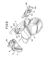
- the structure shown therein further includes a wheel apron 2 at each side.
- the wheel apron 2 is connected at the rear end with the hinge pillar 18 and extends forward from the hinge pillar 18 to define a side wall of the engine compartment A.
- the front end of the wheel apron 2 is connected with the upper portion of each end of the radiator shroud 3.
- the wheel apron 2 is formed with a wheel arch 4 which bulges inward into the engine compartment A to provide a room for a front wheel (not shown) outside the wheel apron 2.
- the wheel apron 2 is provided with a front frame 5 which is of a channel-shaped cross-sectional configuration and welded at the opposite side edges to the lower edge portion of the wheel apron 2 to form a structure of closed cross-section.
- the wheel apron 2 is formed with a cutout 4a at the top portion of the wheel arch 4 and a suspension tower 6 is connected with the wheel apron 2 to cover the cutout 4a.
- the suspension tower 6 comprises a side wall 7 and a top wall 8 which are connected together and the top wall 8 is adapted to receive, as shown in Figure 2, the top end of a suspension strut assembly 9 which extends upward through the cutout 4a in the wheel apron 2.
- the suspension strut assembly 9 is shown as including a damper strut 10 and a coil spring 11.
- the wheel apron 2 is provided with a wheel apron reinforcement 12 and an upper reinforcement 13 as shown in Figures 1 and 4.
- the wheel apron reinforcement 12 includes an inner reinforcement member 14 and an outer reinforcement member 15.
- the inner member 14 is substantially of an L-shaped cross-section having a vertical leg 14A and a transversely outwardly extending flange 14B which is contiguous to the upper edge of the vertical leg 14A.
- the inner member 14 extends between the hinge pillar 18 and the radiator shroud throughout the length of the wheel apron 2 so that the lower edge of the vertical leg 14 is located substantially at the level of the top of the wheel arch 4.
- the inner member 14 is welded at the vertical leg 14A to the wheel apron 2 as shown in Figures 9, 10 and 11.
- the radiator shroud 3 includes an upper frame member 16 and a head lamp panel 17 which are connected to the front end of the wheel apron 2.
- the inner member 14 of the wheel apron reinforcement 2 extends to the portion where the upper frame member 16 of the radiator shroud 3 is connected to the wheel apron 2.
- the inner member 14 has a front end 14a which is connected to the upper frame member 16 of the radiator shroud 3. It will therefore be understood that the connection between the radiator shroud 3 and the wheel apron 2 is reinforced by the inner member 14 of the wheel apron reinforcement 12.
- the outer member 15 of the wheel apron reinforcement 12 is of a substantially Z-shaped cross-section having a vertical wall 15A, a transversely inwardly extending lower flange 15B and a transversely outwardly extending upper flange 15C.
- the outer member 15 extends forward from the rear end of the inner member 14 and connected to the inner member 14 by being welded at the edge portion of the lower flange 15B to the vertical wall 14A of the inner member 14 and at the upper flange 15C to the flange 14B of the inner member 14.
- a reinforcement structure of closed cross-section is formed by the inner member 14 and the outer member 15 of the wheel apron reinforcement 12.
- the members 14 and 15 are connected at the rear ends to the hinge pillar 18.
- the upper reinforcement 13 is of a configuration as shown in Figure 7 and located above the wheel apron reinforcement 12 at the rear portion of the wheel apron 2.
- the reinforcement 13 is connected to the wheel apron 2, to the flange 14B of the inner member 14 of the wheel apron reinforcement 12 and to the hinge pillar 18 to thereby reinforce the rear upper portion as shown in Figure 11.
- the wheel apron 2 has a height which increases toward rearward and the reinforcement 13 is correspondingly increased in height toward rearward. Further, the reinforcement 13 has a front end portion which is tapered toward forward. The front end of the reinforcement 13 is located forward the suspension tower 6 so that the load from the suspension strut 9 is supported by the reinforcement 13.
- the wheel apron 2 is formed at a portion above the wheel arch 4 with an inward projection 21 which continues at the upper end through a wall 23 to an outward projection 22.
- the inner member 14 of the wheel apron reinforcement 12 is formed with an inward projection 14b which corresponds in configuration with the inward projection 21 on the wheel apron 2 and is fitted to the recess formed in the wheel apron 2 by the inward projection 21.
- the top wall 8 of the suspension tower 6 has an outward extension 8a which is laid on the wall 23 and connected to the wheel apron 2 together with the inner member 14 of the wheel apron reinforcement 12 and the upper reinforcement 13 as shown in Figure 3.
- the outer side of the wheel apron 2 is covered by a front fender 24.
- the side door 30 is provided with a longitudinally extending impact bar structure 32 for reinforcing the door 30 against a longitudinal force.
- the side door 30 includes an outer panel 33 and an inner panel 34.
- the impact bar structure 32 includes a flat member 35 attached to the outer panel 33 through spacing members 36 and a hat shaped member 37, the members 35 and 37 being connected together to form a structure of closed cross-section. Between the members 35 and 37, a reinforcement 38 is located. It will be noted in Figure 4 that the impact bar structure 32 is located at a heightwise level substantially the same as that of the wheel apron reinforcement 12.
- the front end 15a of the outer member 15 of the wheel apron reinforcement 12 is located at a position rearwardly spaced from the radiator shroud 3 and the height of the member 15 is gradually increased toward rearward.
- the wheel apron 2 is collapsed at first at the front end portion where only the inner member 14 is provided for reinforcement.
- the shock load is large so that the load is not absorbed only by the collapsing of the front portion
- the wheel apron reinforcement 12 starts to be collapsed at the front end portion of the outer member 15 and the collapsing gradually progresses toward rearward depending on the shock load.
- the shock load is then transmitted through the impact bar structures 32 in the side doors 30 to the rear body so that deformation of the passenger compartment can be suppressed to minimum.
Abstract
Description
- The present invention relates to a motor vehicle front body structure and more particularly to a vehicle front body structure having a front engine compartment.
- In a motor vehicle body having an engine compartment located forward the passanger compartment, side walls of the engine compartment are constituted by wheel aprons which extend forward from front hinge pillars. The front ends of the wheel aprons are connected to the opposite ends of a transversely extending radiator shroud. The wheel apron is provided at the transversely inner side with a suspension tower for receiving an upper, end of a suspension strut assembly. In order to provide the wheel apron with a sufficient strength and rigidity, it has been known to form longitudinally extending frame structures of closed cross-section along upper and lower portions of the wheel apron. Examples of such front body structure are shown by Japanese utility model application 54-14604 which has been filed on February 6, 1979 and disclosed for public inspection on August 13, 1980 under the disclosure number 55-114772.
- It is an object of the present invention to provide a motor vehicle front body structure having a wheel apron reinforced by a longitudinally extending reinforcement with further means for reinforcing the connection between the wheel apron and the radiator shroud.
- Another object of the present invention is to provide a front body structure wherein the wheel apron is reinforced so that the structure forming the engine compartment is gradually collapsed from the forward end portion in case of a crash of the vehicle body.
- According to the present invention, the above and other objects can be accomplished by a motor vehicle front body structure including a pair of wheel aprons, each extending forward from a hinge pillar to define a side wall of an engine compartment, a substantially transversely extending radiator shroud having opposite ends which are connected respectively to front ends of said wheel aprons, a wheel apron reinforcement structure provided on an outer side of each wheel apron to extend between and connected with said hinge pillar and said radiator shroud, said wheel apron reinforcement structure including a portion of closed cross-section which extends from said hinge pillar forward to a . longitudinal position spaced apart rearward from said radiator shroud by a predetermined distance, said portion of closed cross-section being increased in height toward rearward.
- According to a preferable aspect of the present invention, the wheel apron reinforcement structure comprises a reinforcement inner panel extending between the hinge pillar and the radiator shroud and having a front end portion connected with the radiator shroud, and a reinforcement outer panel extending between the hinge pillar and said longitudinal position and connected with said reinforcement inner panel to form said portion of closed cross-section. The wheel apron reinforcement structure is connected at the front end with the radiator shroud so that the connection between the wheel apron and the radiator shroud is reinforced by this structure. Since the wheel apron reinforcement is not of a closed cross-section between the radiator shroud and the aforementioned longitudinal position, this portion is at first collapsed under the shock load in crash to thereby absorb the shock load. In case where the shock load cannot be fully absorbed by the collapsing of the aforementioned portion, the remaining portion of the wheel apron reinforcement structure is then collapsed. Since the height of the reinforcement structure is gradually increased toward rearward, the collapsing is gradually proceeded toward rearward.
- The above and other objects and features of the present invention will become apparent from the following description of a preferred embodiment taking reference to the accompanying drawings.
-
- Figure 1 is a fragmentary perspective view of a motor vehicle front body structure embodying the features of the present invention;
- Figure 2 is a sectional view taken along a transverse vertical plane passing through the suspention tower;
- Figure 3 is an enlarged sectional view showing the arrangement of the wheel apron reinforcement structure in the vicinity of the suspension tower;
- Figure 4 is a side view of the side structure as seen from the outside;
- Figure 5 is an exploded perspective view of the structural components in the side structure;
- Figure 6 is an exploded perspective view of the wheel apron reinforcement structure;
- Figure 7 is a perspective view of the rear upper reinforcement;
- Figure 8 is a top plan view of the side structure;
- Figure 9 is a sectional view taken along the line IX-IX in Figure 4;
- Figure 10 is a sectional view taken along the line X-X in Figure 4;
- Figure 11 is a sectional view taken along the line XI-XI in Figure 4; and,
- Figure 12 is a sectional view taken along the line XII-XII in the Figure 4.
- Referring to the drawings, particularly to Figure 1, there is shown a motor vehicle front body structure including a dash panel 1 which separates the front engine compartment A from the rear passenger compartment B. Each end of the dash panel 1 is connected with a front
door hinge pillar 18 of a closed cross-section as well known in the art. As shown in Figure 4, thehinge pillar 18 is upwardly extended to form a front pillar 19. The lower end of thehinge pillar 18 is connected with a rearwardly extendingside sill 20 which is also well known in the art. Thehinge pillar 18 and the front pillar 19 define a front periphery of a side door opening and theside sill 20 define a lower periphery of the side door opening. Aside door 30 is provided in the door opening and connected with thehinge pillar 18 by means ofhinges 31. - Referring again to Figure 1, it will be noted that the structure shown therein further includes a
wheel apron 2 at each side. Thewheel apron 2 is connected at the rear end with thehinge pillar 18 and extends forward from thehinge pillar 18 to define a side wall of the engine compartment A. Between the front ends of thewheel aprons 2 at the opposite sides of the structure, there is a transversely extendingradiator shroud 3 which defines a front wall of the engine compartment A. As shown in Figures 1 and 8, the front end of thewheel apron 2 is connected with the upper portion of each end of theradiator shroud 3. - The
wheel apron 2 is formed with awheel arch 4 which bulges inward into the engine compartment A to provide a room for a front wheel (not shown) outside thewheel apron 2. Along the lower edge, thewheel apron 2 is provided with afront frame 5 which is of a channel-shaped cross-sectional configuration and welded at the opposite side edges to the lower edge portion of thewheel apron 2 to form a structure of closed cross-section. As shown in Figure 5, thewheel apron 2 is formed with acutout 4a at the top portion of thewheel arch 4 and asuspension tower 6 is connected with thewheel apron 2 to cover thecutout 4a. - As shown in Figure 5, the
suspension tower 6 comprises a side wall 7 and atop wall 8 which are connected together and thetop wall 8 is adapted to receive, as shown in Figure 2, the top end of asuspension strut assembly 9 which extends upward through thecutout 4a in thewheel apron 2. In Figure 2, it will be noted that thesuspension strut assembly 9 is shown as including adamper strut 10 and acoil spring 11. - At the upper portion, the
wheel apron 2 is provided with awheel apron reinforcement 12 and anupper reinforcement 13 as shown in Figures 1 and 4. As shown in Figure 6, thewheel apron reinforcement 12 includes aninner reinforcement member 14 and anouter reinforcement member 15. Theinner member 14 is substantially of an L-shaped cross-section having avertical leg 14A and a transversely outwardly extendingflange 14B which is contiguous to the upper edge of thevertical leg 14A. Theinner member 14 extends between thehinge pillar 18 and the radiator shroud throughout the length of thewheel apron 2 so that the lower edge of thevertical leg 14 is located substantially at the level of the top of thewheel arch 4. Theinner member 14 is welded at thevertical leg 14A to thewheel apron 2 as shown in Figures 9, 10 and 11. - As shown in Figure 1, the
radiator shroud 3 includes anupper frame member 16 and ahead lamp panel 17 which are connected to the front end of thewheel apron 2. Theinner member 14 of thewheel apron reinforcement 2 extends to the portion where theupper frame member 16 of theradiator shroud 3 is connected to thewheel apron 2. Theinner member 14 has afront end 14a which is connected to theupper frame member 16 of theradiator shroud 3. It will therefore be understood that the connection between theradiator shroud 3 and thewheel apron 2 is reinforced by theinner member 14 of thewheel apron reinforcement 12. - The
outer member 15 of thewheel apron reinforcement 12 is of a substantially Z-shaped cross-section having avertical wall 15A, a transversely inwardly extendinglower flange 15B and a transversely outwardly extending upper flange 15C. Theouter member 15 extends forward from the rear end of theinner member 14 and connected to theinner member 14 by being welded at the edge portion of thelower flange 15B to thevertical wall 14A of theinner member 14 and at the upper flange 15C to theflange 14B of theinner member 14. Thus, a reinforcement structure of closed cross-section is formed by theinner member 14 and theouter member 15 of thewheel apron reinforcement 12. Themembers hinge pillar 18. - The
upper reinforcement 13 is of a configuration as shown in Figure 7 and located above thewheel apron reinforcement 12 at the rear portion of thewheel apron 2. Thereinforcement 13 is connected to thewheel apron 2, to theflange 14B of theinner member 14 of thewheel apron reinforcement 12 and to thehinge pillar 18 to thereby reinforce the rear upper portion as shown in Figure 11. Thewheel apron 2 has a height which increases toward rearward and thereinforcement 13 is correspondingly increased in height toward rearward. Further, thereinforcement 13 has a front end portion which is tapered toward forward. The front end of thereinforcement 13 is located forward thesuspension tower 6 so that the load from thesuspension strut 9 is supported by thereinforcement 13. - In Figures 3, 5 and 8, it will be noted that the
wheel apron 2 is formed at a portion above thewheel arch 4 with aninward projection 21 which continues at the upper end through awall 23 to anoutward projection 22. Theinner member 14 of thewheel apron reinforcement 12 is formed with aninward projection 14b which corresponds in configuration with theinward projection 21 on thewheel apron 2 and is fitted to the recess formed in thewheel apron 2 by theinward projection 21. Thetop wall 8 of thesuspension tower 6 has anoutward extension 8a which is laid on thewall 23 and connected to thewheel apron 2 together with theinner member 14 of thewheel apron reinforcement 12 and theupper reinforcement 13 as shown in Figure 3. The outer side of thewheel apron 2 is covered by afront fender 24. - In Figure 4, it will be noted that the
side door 30 is provided with a longitudinally extendingimpact bar structure 32 for reinforcing thedoor 30 against a longitudinal force. As shown in Figure 12, theside door 30 includes anouter panel 33 and aninner panel 34. Theimpact bar structure 32 includes aflat member 35 attached to theouter panel 33 throughspacing members 36 and a hat shapedmember 37, themembers members reinforcement 38 is located. It will be noted in Figure 4 that theimpact bar structure 32 is located at a heightwise level substantially the same as that of thewheel apron reinforcement 12. - It will further be noted in Figure 4 that the
front end 15a of theouter member 15 of thewheel apron reinforcement 12 is located at a position rearwardly spaced from theradiator shroud 3 and the height of themember 15 is gradually increased toward rearward. In case where the car has crashed at the front end, therefore, thewheel apron 2 is collapsed at first at the front end portion where only theinner member 14 is provided for reinforcement. Where the shock load is large so that the load is not absorbed only by the collapsing of the front portion, thewheel apron reinforcement 12 starts to be collapsed at the front end portion of theouter member 15 and the collapsing gradually progresses toward rearward depending on the shock load. The shock load is then transmitted through theimpact bar structures 32 in theside doors 30 to the rear body so that deformation of the passenger compartment can be suppressed to minimum. - The invention has thus been shown and described with reference to a specific embodiment, however, it should be noted that the invention is in no way limited to the details of the illustrated structures but changes and modifications may be made without departing from the scope of the appended claims.
Claims (14)
Applications Claiming Priority (6)
| Application Number | Priority Date | Filing Date | Title |
|---|---|---|---|
| JP87739/85 | 1985-04-23 | ||
| JP8774085A JPS61244675A (en) | 1985-04-23 | 1985-04-23 | Front body construction of car |
| JP8773985A JPH0662097B2 (en) | 1985-04-23 | 1985-04-23 | Front body structure of automobile |
| JP87740/85 | 1985-04-23 | ||
| JP1985063459U JPH0127499Y2 (en) | 1985-04-27 | 1985-04-27 | |
| JP63459/85U | 1985-04-27 |
Publications (3)
| Publication Number | Publication Date |
|---|---|
| EP0200154A2 true EP0200154A2 (en) | 1986-11-05 |
| EP0200154A3 EP0200154A3 (en) | 1987-07-29 |
| EP0200154B1 EP0200154B1 (en) | 1990-07-18 |
Family
ID=27298185
Family Applications (1)
| Application Number | Title | Priority Date | Filing Date |
|---|---|---|---|
| EP86105638A Expired - Lifetime EP0200154B1 (en) | 1985-04-23 | 1986-04-23 | Front body structure for front engine type motor vehicle |
Country Status (3)
| Country | Link |
|---|---|
| US (1) | US4669777A (en) |
| EP (1) | EP0200154B1 (en) |
| DE (1) | DE3672665D1 (en) |
Cited By (3)
| Publication number | Priority date | Publication date | Assignee | Title |
|---|---|---|---|---|
| EP0555744A1 (en) * | 1992-02-10 | 1993-08-18 | Adam Opel Aktiengesellschaft | Wheel mounting in vehicle bodies |
| EP1997720A1 (en) | 2007-06-01 | 2008-12-03 | Nissan Motor Co., Ltd. | Front vehicle body structure |
| DE102014009943B4 (en) | 2013-07-08 | 2019-03-14 | Suzuki Motor Corporation | The vehicle body front part structure |
Families Citing this family (15)
| Publication number | Priority date | Publication date | Assignee | Title |
|---|---|---|---|---|
| US4723811A (en) * | 1985-04-27 | 1988-02-09 | Mazda Motor Corporation | Front body structure for motor vehicle |
| US4909565A (en) * | 1987-04-17 | 1990-03-20 | Mazda Motor Corporation | Front body construction |
| JPH0518231Y2 (en) * | 1987-08-01 | 1993-05-14 | ||
| WO1992011168A1 (en) * | 1990-12-20 | 1992-07-09 | Audi Ag | Bearer joint, especially longitudinal bearer joint, in coachwork for a passenger car |
| DE59102874D1 (en) * | 1990-12-20 | 1994-10-13 | Audi Ag | CARRYING STRUCTURE OF A BODY OF A PERSONAL VEHICLE. |
| DE19621943C2 (en) * | 1996-05-31 | 2000-12-07 | Daimler Chrysler Ag | Front wall for a vehicle body |
| JP2000108938A (en) * | 1998-09-30 | 2000-04-18 | Fuji Heavy Ind Ltd | Front body construction of automobile |
| US6601873B1 (en) * | 1999-04-16 | 2003-08-05 | Daimlerchrysler Ag | Motor vehicle having a crumple zone, passenger compartment and deflecting ramps |
| DE19923737B4 (en) * | 1999-05-22 | 2004-08-05 | Daimlerchrysler Ag | Multi-part end wall for a motor vehicle bodyshell |
| DE10023194B4 (en) * | 2000-05-11 | 2004-10-14 | Dr.Ing.H.C. F. Porsche Ag | Body structure for a motor vehicle with front strut mounts |
| KR100392086B1 (en) * | 2000-11-24 | 2003-07-23 | 현대자동차주식회사 | Cowl side part T type box structure of vehicle |
| DE10208512B4 (en) * | 2002-02-27 | 2008-11-13 | Daimler Ag | Support structure of a motor vehicle |
| JP3988745B2 (en) * | 2004-05-06 | 2007-10-10 | 日産自動車株式会社 | Body floor structure |
| DE102013209099A1 (en) * | 2013-05-16 | 2014-11-20 | Bayerische Motoren Werke Aktiengesellschaft | Spring support for a motor vehicle |
| FR3016600B1 (en) * | 2014-01-23 | 2016-01-22 | Renault Sas | BODY STRUCTURE OF A MOTOR VEHICLE WITH REPLACEMENT REINFORCEMENTS OF EFFORTS RELATING TO A REAR SHOCK ABSORBER OF THE VEHICLE |
Citations (4)
| Publication number | Priority date | Publication date | Assignee | Title |
|---|---|---|---|---|
| US3596978A (en) * | 1969-07-16 | 1971-08-03 | Budd Co | Combined a-post, cowl and wheelhouse structure |
| US4270793A (en) * | 1978-10-02 | 1981-06-02 | Toyo Kogyo Co., Ltd. | Automobile front deck structure |
| US4466653A (en) * | 1981-09-18 | 1984-08-21 | Toyo Kogyo Co., Ltd. | Automobile front body structure |
| FR2544272A1 (en) * | 1983-04-13 | 1984-10-19 | Honda Motor Co Ltd | VEHICLE CHASSIS REINFORCED LATERALLY |
Family Cites Families (6)
| Publication number | Priority date | Publication date | Assignee | Title |
|---|---|---|---|---|
| JPS5928285B2 (en) * | 1977-06-09 | 1984-07-12 | 松下電器産業株式会社 | phase inversion circuit |
| JPS5911464B2 (en) * | 1978-11-10 | 1984-03-15 | 日産自動車株式会社 | car body structure |
| JPS55114772A (en) * | 1979-02-23 | 1980-09-04 | Hitachi Ltd | Door opening*closing controller |
| JPS5675273A (en) * | 1979-11-19 | 1981-06-22 | Nissan Motor Co Ltd | Cowl structure for car |
| DE3114379C2 (en) * | 1981-04-09 | 1986-11-20 | Dr.Ing.H.C. F. Porsche Ag, 7000 Stuttgart | Body structure of a passenger car |
| US4545612A (en) * | 1981-08-26 | 1985-10-08 | Mazda Motor Corporation | Front side structure of an automobile body |
-
1986
- 1986-04-22 US US06/854,592 patent/US4669777A/en not_active Expired - Fee Related
- 1986-04-23 EP EP86105638A patent/EP0200154B1/en not_active Expired - Lifetime
- 1986-04-23 DE DE8686105638T patent/DE3672665D1/en not_active Expired - Fee Related
Patent Citations (4)
| Publication number | Priority date | Publication date | Assignee | Title |
|---|---|---|---|---|
| US3596978A (en) * | 1969-07-16 | 1971-08-03 | Budd Co | Combined a-post, cowl and wheelhouse structure |
| US4270793A (en) * | 1978-10-02 | 1981-06-02 | Toyo Kogyo Co., Ltd. | Automobile front deck structure |
| US4466653A (en) * | 1981-09-18 | 1984-08-21 | Toyo Kogyo Co., Ltd. | Automobile front body structure |
| FR2544272A1 (en) * | 1983-04-13 | 1984-10-19 | Honda Motor Co Ltd | VEHICLE CHASSIS REINFORCED LATERALLY |
Cited By (4)
| Publication number | Priority date | Publication date | Assignee | Title |
|---|---|---|---|---|
| EP0555744A1 (en) * | 1992-02-10 | 1993-08-18 | Adam Opel Aktiengesellschaft | Wheel mounting in vehicle bodies |
| EP1997720A1 (en) | 2007-06-01 | 2008-12-03 | Nissan Motor Co., Ltd. | Front vehicle body structure |
| US7594692B2 (en) | 2007-06-01 | 2009-09-29 | Nissan Motor Co., Ltd. | Front vehicle body structure |
| DE102014009943B4 (en) | 2013-07-08 | 2019-03-14 | Suzuki Motor Corporation | The vehicle body front part structure |
Also Published As
| Publication number | Publication date |
|---|---|
| EP0200154B1 (en) | 1990-07-18 |
| EP0200154A3 (en) | 1987-07-29 |
| US4669777A (en) | 1987-06-02 |
| DE3672665D1 (en) | 1990-08-23 |
Similar Documents
| Publication | Publication Date | Title |
|---|---|---|
| US4723811A (en) | Front body structure for motor vehicle | |
| US4669777A (en) | Front body structure for front engine type motor vehicle | |
| US4950025A (en) | Automobile rear body structure | |
| JPH0750301Y2 (en) | Front body structure of automobile | |
| KR960003520Y1 (en) | Automobile lower body structure | |
| JPH0966864A (en) | Automobile body structure | |
| JP2004520224A (en) | Vehicle door inner panel | |
| CN115443239B (en) | Vehicle body | |
| JP3112978B2 (en) | Car rear body structure | |
| EP3566931B1 (en) | Vehicle body structure, and vehicle | |
| CN214138710U (en) | Vehicle body side structure | |
| JPS62181976A (en) | Structure of lower body by vehicle | |
| JP3148764B2 (en) | Car side body structure | |
| JPH06144299A (en) | Lower body structure of automobile | |
| JP4715039B2 (en) | Vehicle side body structure | |
| CN113492922A (en) | Front body structure of vehicle | |
| JPH0138711B2 (en) | ||
| JPH0116713B2 (en) | ||
| JP4304432B2 (en) | Front body structure of the vehicle | |
| JPH04293680A (en) | Front body structure for vehicle | |
| JPH0134938Y2 (en) | ||
| JPS61244674A (en) | Front body construction of car | |
| JPS6236686Y2 (en) | ||
| JPS6113407Y2 (en) | ||
| JP2938945B2 (en) | Car front body structure |
Legal Events
| Date | Code | Title | Description |
|---|---|---|---|
| PUAI | Public reference made under article 153(3) epc to a published international application that has entered the european phase |
Free format text: ORIGINAL CODE: 0009012 |
|
| 17P | Request for examination filed |
Effective date: 19860423 |
|
| AK | Designated contracting states |
Kind code of ref document: A2 Designated state(s): DE FR GB |
|
| PUAL | Search report despatched |
Free format text: ORIGINAL CODE: 0009013 |
|
| AK | Designated contracting states |
Kind code of ref document: A3 Designated state(s): DE FR GB |
|
| 17Q | First examination report despatched |
Effective date: 19890413 |
|
| GRAA | (expected) grant |
Free format text: ORIGINAL CODE: 0009210 |
|
| AK | Designated contracting states |
Kind code of ref document: B1 Designated state(s): DE FR GB |
|
| REF | Corresponds to: |
Ref document number: 3672665 Country of ref document: DE Date of ref document: 19900823 |
|
| ET | Fr: translation filed | ||
| PLBE | No opposition filed within time limit |
Free format text: ORIGINAL CODE: 0009261 |
|
| STAA | Information on the status of an ep patent application or granted ep patent |
Free format text: STATUS: NO OPPOSITION FILED WITHIN TIME LIMIT |
|
| 26N | No opposition filed | ||
| PGFP | Annual fee paid to national office [announced via postgrant information from national office to epo] |
Ref country code: FR Payment date: 19950411 Year of fee payment: 10 |
|
| PGFP | Annual fee paid to national office [announced via postgrant information from national office to epo] |
Ref country code: GB Payment date: 19950412 Year of fee payment: 10 |
|
| PGFP | Annual fee paid to national office [announced via postgrant information from national office to epo] |
Ref country code: DE Payment date: 19950421 Year of fee payment: 10 |
|
| PG25 | Lapsed in a contracting state [announced via postgrant information from national office to epo] |
Ref country code: GB Effective date: 19960423 |
|
| GBPC | Gb: european patent ceased through non-payment of renewal fee |
Effective date: 19960423 |
|
| PG25 | Lapsed in a contracting state [announced via postgrant information from national office to epo] |
Ref country code: FR Effective date: 19961227 |
|
| PG25 | Lapsed in a contracting state [announced via postgrant information from national office to epo] |
Ref country code: DE Effective date: 19970101 |
|
| REG | Reference to a national code |
Ref country code: FR Ref legal event code: ST |