EP0203816B1 - Optical disc drive apparatus - Google Patents
Optical disc drive apparatus Download PDFInfo
- Publication number
- EP0203816B1 EP0203816B1 EP86304080A EP86304080A EP0203816B1 EP 0203816 B1 EP0203816 B1 EP 0203816B1 EP 86304080 A EP86304080 A EP 86304080A EP 86304080 A EP86304080 A EP 86304080A EP 0203816 B1 EP0203816 B1 EP 0203816B1
- Authority
- EP
- European Patent Office
- Prior art keywords
- optical
- objective lens
- rotatable
- optical disc
- light beam
- Prior art date
- Legal status (The legal status is an assumption and is not a legal conclusion. Google has not performed a legal analysis and makes no representation as to the accuracy of the status listed.)
- Expired - Lifetime
Links
Images


Classifications
-
- G—PHYSICS
- G11—INFORMATION STORAGE
- G11B—INFORMATION STORAGE BASED ON RELATIVE MOVEMENT BETWEEN RECORD CARRIER AND TRANSDUCER
- G11B7/00—Recording or reproducing by optical means, e.g. recording using a thermal beam of optical radiation by modifying optical properties or the physical structure, reproducing using an optical beam at lower power by sensing optical properties; Record carriers therefor
- G11B7/12—Heads, e.g. forming of the optical beam spot or modulation of the optical beam
- G11B7/135—Means for guiding the beam from the source to the record carrier or from the record carrier to the detector
-
- G—PHYSICS
- G11—INFORMATION STORAGE
- G11B—INFORMATION STORAGE BASED ON RELATIVE MOVEMENT BETWEEN RECORD CARRIER AND TRANSDUCER
- G11B7/00—Recording or reproducing by optical means, e.g. recording using a thermal beam of optical radiation by modifying optical properties or the physical structure, reproducing using an optical beam at lower power by sensing optical properties; Record carriers therefor
- G11B7/08—Disposition or mounting of heads or light sources relatively to record carriers
- G11B7/085—Disposition or mounting of heads or light sources relatively to record carriers with provision for moving the light beam into, or out of, its operative position or across tracks, otherwise than during the transducing operation, e.g. for adjustment or preliminary positioning or track change or selection
- G11B7/0857—Arrangements for mechanically moving the whole head
- G11B7/08576—Swinging-arm positioners
-
- G—PHYSICS
- G11—INFORMATION STORAGE
- G11B—INFORMATION STORAGE BASED ON RELATIVE MOVEMENT BETWEEN RECORD CARRIER AND TRANSDUCER
- G11B7/00—Recording or reproducing by optical means, e.g. recording using a thermal beam of optical radiation by modifying optical properties or the physical structure, reproducing using an optical beam at lower power by sensing optical properties; Record carriers therefor
- G11B7/08—Disposition or mounting of heads or light sources relatively to record carriers
- G11B7/09—Disposition or mounting of heads or light sources relatively to record carriers with provision for moving the light beam or focus plane for the purpose of maintaining alignment of the light beam relative to the record carrier during transducing operation, e.g. to compensate for surface irregularities of the latter or for track following
- G11B7/0941—Methods and circuits for servo gain or phase compensation during operation
Landscapes
- Physics & Mathematics (AREA)
- Optics & Photonics (AREA)
- Optical Recording Or Reproduction (AREA)
- Optical Head (AREA)
- Moving Of The Head For Recording And Reproducing By Optical Means (AREA)
- Length Measuring Devices By Optical Means (AREA)
Description
- The present invention relates to an optical disc drive apparatus for recording or reproducing information using an optical disk as a recording medium.
- Japanese Laid-Open Patent Application No. 58-91536 discloses an optical disc drive apparatus in which information is recorded on an optical disc along a track with a width of several µm. To this end it is necessary to focus a laser beam to a spot by means of an objective lens and apply the spot onto the track accurately. Thus, it is necessary to effect accurate tracking control. In order to achieve this, it has heretofore been necessary to construct an optical disc drive apparatus with a rough actuator and a fine actuator provided on the rough actuator.
- The recording density of an optical disc is about 10 to 100 times higher than that of a magnetic disc. In a comparison of 5-inch one-side discs, a replaceable floppy disc has a memory capacity of about 1MB and a fixed type disc for Winchester drives has a memory capacity of about 10MB, while an optical disc has a memory capacity of about 200MB or even more.
- Therefore, an optical disc is so formed as to have a fairly fine track width as compared with that of a magnetic disc, and consequently the accuracy in positioning a laser beam which corresponds to a recording/reproducing head, relative to the track, becomes more strict than that in a magnetic disc apparatus. The track width of a floppy disc is about 500 µm and that of a fixed type disc about several ten µm, while that of an optical disc is at most 2 µm. Positioning a laser beam spot of about 1 µm in diameter accurately onto such a fine track is difficult with positioning means used for the magnetic disc. Besides, since the optical disc, like the floppy disc, is used as a replaceable medium, there occurs a positional error at the time of disc change, resulting in that the track does not rotate circularly but rotates eccentrically unlike the rotation of the fixed disc.
- Generally, in an optical disc drive apparatus, the position of a laser beam spot relative to a track is corrected using a feedback control, thereby permitting recording or reproduction along the track. To this end, the conventional optical disc drive apparatus is provided with the two-stage actuators - a rough actuator and a fine actuator.
- The rough actuator exhibits a function similar to that of the positioning means for the magnetic disc drive apparatus,in which the laser beam spot is positioned using a mechanical means. The fine actuator is provided on the rough actuator for shifting the laser beam accurately within a specified range and correcting a positional error of the rough actuator.
- In such conventional optical disc drive apparatus, however, the operation for moving the laser beam from one track to another, namely, track seek has been inferior to that of the magnetic disc drive apparatus. In the magnetic disc drive apparatus, what is required is merely moving a recording/reproducing head by means of a positioning mechanism, while in the conventional optical disc drive apparatus the fine actuator must be moved by the rough actuator as mentioned above. The mass of the recording/reproducing head of the magnetic disc drive apparatus is several grams at most, but that of the fine actuator is inevitably several ten grams or more because it carries thereon optical components, e.g. galvanomirror, for scanning the laser beam. Consequently, the speed of track seek becomes lower in proportion to the increase in conveyance mass. Of more importance is that the precision actuator is a precise and fragile component. Even if the rough actuator can move at high speed, the precision actuator will be unable to withstand a large acceleration induced at that time.
- There has also been proposed an optical disc drive apparatus without the precision actuator as disclosed, for example, in Japanese Laid-Open Patent Application No. 58-53035, in which an optical head is mounted near the fore end of a rotary actuator. Generally speaking, the positioning accuracy of a rotary actuator is higher than that of a linear actuator. Because a rotation support mechanism constituted by bearings and shaft can be sealed hermetically and therefore dust or the like does not adhere thereto, thus permitting a smoother operation than the linear structure. Thus, the rotary actuator can function as both rough and precision actuators.
- However, the rotary actuator has such drawbacks that a mechanical resonance is apt to occur as compared with the linear actuator and that therefore it is impossible to increase the response frequency of a tracking servo system and hence it is impossible to increase the number of rotations of the disc. Consequently, the use of an optical disc drive apparatus having such a structure is restricted to the case where an optical disc is rotated at low speed, for example, for digital audio.
- US Patent No. 4,004,081 discloses another type of optical pick-up system which has an objective lens, two mirrors and a photo sensor mounted on a rotary actuator. In this system, to reduce the moving mass, a laser beam source is located outside of the rotary actuator. Further, no independent precision actuator is provided to avoid an increase of the moving mass, and the rotary actuator operates as both a rough actuator and a precision actuator in a manner similar to the system disclosed in Japanese Laid-Open Patent Application No. 58-53035.
- US Patent No. 3,324,075 discloses still another type of optical pick-up system which has a rotatable optical head for recording information on an optical tape wound on a rotary cylinder. This system has an optical deflector operating as both a rough actuator and a precision actuator. To reduce off-axial incident on an objective lens caused by the optical deflection, the system uses a telescope lens system which can absorb the axial diviation. Such system, which is complicated in structure and thus heavy in weight, is not suitable to an optical disc drive system, which requires an actuator with a small moving mass.
- The present invention provides an optical disc drive apparatus for recording information on a recording surface of an optical disc in the form of information tracks and reproducing the recorded information with a light beam, comprising:
an optical system for emitting a light beam and receiving a reflected light beam from the surface of said optical disc to record and reproduce information;
an objective lens for focusing the light beam emitted from said optical system and passed along an optical path between said optical system and said objective lens to form a light spot on the surface of said optical disc and returning the reflected light beam from the surface of said optical disc to said optical path;
a rotatable means rotatable along its rotational axis for moving said objective lens in a direction crossing the information tracks of said optical disc to effect coarse tracking of the light spot on a desired information track, said optical system being located stationary with respect to said rotatable means at an input side of said optical path such that the light beam emitted from said optical system is passed substantially along the rotational axis of said rotatable means;
a light guide means mounted on said rotatable means for guiding the light beam passed substantially along the rotational axis of said rotatable means to said objective lens;
characterized by further comprising an optical path deflecting means located stationary with respect to said rotatable means at the input side of said optical path for deflecting the light beam emitted from said optical system, said deflecting means being movable for effecting fine tracking of said light spot on the desired information track. - A preferred form of optical disc drive apparatus according to the invention has a track seeking ability equal to that of a magnetic disc drive apparatus.
- In order that the present invention by more readily understood, embodiments thereof will now be described by way of example with reference to the accompanying drawings, in which:
- Fig. 1 is a perspective view of an optical disc drive apparatus according to a first embodiment of the present invention;
- Fig. 2 is an explanatory view showing an example of a light guide means used in the first embodiment and its operation;
- Fig. 3 is an explanatory view showing the operation of an optical path deflecting means used in the first embodiment;
- Fig. 4 is a block diagram of a control system used in the first embodiment;
- Figs. 5, 6 and 7 are graphs showing transfer characteristics of the control system of Fig. 4;
- Fig. 8 is a perspective view of an optical disc drive apparatus according to a second embodiment of the present invention;
- Fig. 9 is a detailed sketch of a focus suspension used in the second embodiment;
- Fig. 10 shows operations of the focus suspension of Fig. 9;
- Fig. 11 is an explanatory view showing two examples of focus suspensions;
- Fig. 12 is a perspective view of an optical disc drive apparatus according to a third embodiment of the present invention;
- Figs. 13 and 14 are explanatory views showing partial operations of the drive apparatus of Fig. 12;
- Fig. 15 is a partial construction diagram illustrating a fourth embodiment of the present invention;
- Fig. 16 is a partial construction diagram illustrating a fifth embodiment of the present invention; and
- Figs. 17 to 21 are schematic structural diagrams showing other examples of optical path deflecting means of the present invention.
- Referring first to Fig. 1, there is illustrated in perspective view an optical disc drive apparatus according to an embodiment of the present invention, in which a light beam emitted from an
optical system 1 passes through an optical path deflecting means 2, a light guide means 3 and anobjective lens 4 to focus on the surface of anoptical disc 11. The light guide means 3 and theobjective lens 4 are provided on a rotatingmeans 5, while theoptical system 1, optical path deflecting means 2 and rotatingmeans 5 are provided on abase 10. Theoptical disc 11 is mounted on aspindle motor 12 which is provided on thebase 10. Theoptical system 1 includes a laser beam source as a light emitting means, a photo detector as a light sensing means, a beam splitting means for optically separating the two, and a lens system for focusing and diverging a laser beam. The optical path deflecting means 2 is constituted by a galvanomirror comprising a mirror 200a and a rotator (motor) 200b. With rotation of the rotating means 5, theobjective lens 4 moves in the form of a circular arc approximately in a radial direction of theoptical disc 11. The rotatingmeans 5 has a rotational shaft which is either hollow or formed of a transparent material at its axis or thereabouts, thereby permitting a light beam to pass through the rotational shaft. The light guide means 3 is composed of two reflectingmembers 3a and 3b which are opposed to each other in parallel. - Fig. 2 shows an example of the light guide means 3 and its operation, in which a light beam incident on the light guide means 3 is reflected by the two reflecting
members 3a and 3b opposed to each other in parallel and reaches theobjective lens 4. Since the reflectingmembers 3a and 3b are parallel to each other, light incident on the reflecting member 3a and light leaving the reflectingmember 3b are parallel to each other. In other words, when the light guide means 3 is seen from the reflecting member 3a side (arrow E in the figure), an image 4' of theobjective lens 4 is seen as if it were located on the other side of the reflecting member 3a and that in parallel with the actualobjective lens 4. With rotation of therotating means 5, the light guide means 3 and theobjective lens 4 also rotate. Theobjective lens 4 per se moves arcuately along the radius of theoptical disc 11 as previously noted. At this time, the image 4' looks like an image rotating about a rotational axis P of therotating means 5. If an optical axis of the light incident on the light guide means 3 is aligned with the rotational axis P and an optical axis of the light leaving the light guide means 3 is aligned with an optical axis of theobjective lens 4, the image 4' will rotate in a stationary state on the rotational axis P. In other words, even if theobjective lens 4 per se performs an arcuate rotational motion, it is optically seen in a stationary condition. Further, an image X' of a track X seen through theobjective lens 4 is also projected in parallel with the track X. Optically, this is almost equal to the movement on a straight line of theobjective lens 4. - From the above it is seen that the light guide means 3 constituted by the two reflecting
members 3a and 3b which are opposed to each other in parallel, has an influence merely as an optical distance. Consequently, an optical positional relation between the optical deflecting means 2 and theobjective lens 4 is as shown equivalently in Fig. 3. The reference mark L represents an optical distance between the optical path deflecting means 2 and theobjective lens 4 and the mark F represents a focal length of theobjective lens 4. When a light beam is deflected at a slight angle ϑg by the optical path deflecting means 2, the position of a focused light spot on theoptical disc 11 shifts by εa. From an optical consideration, the relation of the two is described as follows:
- From the above, the role of the optical path deflecting means 2 and that of the
rotating means 5 are apparent. The optical path deflecting means 2 and therotating means 5 correspond to a fine actuator and a rough actuator, respectively, in the prior art. In other words, track seek and rough tracking are performed by moving theobjective lens 4 arcuately with therotating means 5, while fine tracking is effected by the optical path deflecting means 2. - Under this construction, the conveyance mass during track seek can be diminished to a remarkable extent as compared with that in the prior art. More particularly, in this embodiment it is only the
objective lens 4 and the light guide means 3 that should be conveyed during track seek because the optical path deflecting means 2 which corresponds to the fine actuator is fixed to thebase 10. It may appear that the conveyance mass is not so reduced because of an additional provision of the light guide means 3 which has not been used heretofore. Actually, however, it is only the reflectingmember 3b provided on the side of theobjective lens 4 and some components which hold the reflecting member that have influence on the conveyance mass. This is one of great features of a rotary actuator. It is not that the force required for rotating an object is merely proportional to the mass inherent in the object. It is proportional to the product of the mass inherent in the object and the square of the radius of rotation, namely, moment of inertia. In other words, the moment of inertia means a substantial mass in rotational motion. In this embodiment, the reflectingmember 3b and theobjective lens 4 are positioned near the outermost periphery of the rotational motion, their moment of inertia of the reflecting member 3a positioned near the rotational axis can be regarded as being almost zero. Further, if the motor portion of therotating means 5 which provides a driving force to the light guide means 3 andobjective lens 4 is also disposed near the rotational axis, its moment of inertia can be diminished. As a result, the substantial mass which therotating means 5 must carry becomes smaller as a whole. More particularly, when an optimum design is made for the apparatus, including the movable part of the motor and a shaft or the like for transmitting the driving force of the motor to theobjective lens 4, the conveyance mass of the rotary actuator can be reduced to one third of that of the linear actuator. - Another advantage of the rotary system is that since the rotation support mechanism constituted by bearings and shaft can be sealed hermetically, dust or the like does not adhere thereto, thus permitting a smoother operation than the linear structure. As a result, the track follow-up performance of the
rotating means 5 is improved and the follow-up range covered by the optical path deflecting means 2 may be smaller than that in the prior art. This permits the optical path deflecting means to be disposed near a rotational shaft located far away from the objective lens which deflecting means has heretofore been required to be disposed just near the objective lens, as will be described hereinafter. - A precision tracking can be effected by slightly deflecting the light beam incident on the
objective lens 4 and this is as previously noted. But in this case there arises the problem of a slight deviation of the optical axis. More particularly, the light beam incident on theobjective lens 4 deviates by K:
In other words, theobjective lens 4 deviates by -K from the optical axis at this time. The occurrence of such an optical axis deviation affects the focus control and tracking control. The degree of influence differs depending on how to detect the control signal, but generally speaking, the optical axis deviation must be one twentieth or less of the radius of the objective lens. Since the radius of the lens usually employed is about 2 mm and a focal length thereof is about 4 mm (NA = 0.5), the optical axis deviation must be at most 100 µm. If L is 5 cm, ϑg is equal to 0.12° from theequation 2 . At this time, from theequation 1 , the amount of movement of the light spot is:

Therefore, if the optical path deflecting means 2 and therotating means 5 are controlled so that εa becomes not larger than 8 µm, there will not occur any optical problem. In other words, if therotating means 5 can follow the eccentricity of a track at a spot movement not larger than 8 µm, a fine tracking can be done by the optical path deflecting means 2 while suppressing an optical axis deviation within an allowable range. In the case of a rotary actuator, follow-up at that accuracy can be done to a satisfactory extent. In using a rotary actuator, its mechanical resonance may cause a problem, but this fear is eliminated by controlling the optical path deflecting means 2 and therotating means 5 in the manner described below. - Referring now to Fig. 4, there is illustrated in block diagram a control system used in this embodiment, in which the numeral 60 denotes a primary low pass filter having a cut-off frequency fL.
Numeral 61 represents a rotating mechanism system including the light guide means 3,objective lens 4 androtating means 5, which is a quadratic integral system having a mechanical resonance frequency fres.Numeral 62 denotes a filter (lead lag filter) which advances the phase of the frequency band between fp1 and fp2.Numeral 63 denotes a deflecting mechanism system which is assumed to be described by a spring-mass system. Further, a first order resonance frequency is assumed to be fg. If transfer functions of the four components described above are GL, Ga, Gp and Gg, an open loop gain of the tracking control system is given as:

This is shown in Fig. 5, from which it is seen that in the frequency band higher than fT, Gp·Gg, namely, the control system for the rotating mechanism system, mainly acts, while in the frequency band lower than fT, GL·Ga, namely, the control system for thedeflecting mechanism system 63, mainly acts. The frequency fT represents a crossover frequency between these two control systems. - The operation of this tracking control system is explained as follows. If the number of rotations of the
optical disc 11 is fo and the amount of eccentricity at that time is δ, a follow-up error εo of the entire system is: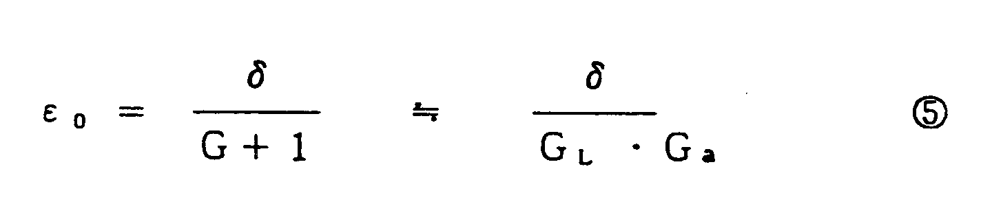
Provided fo < < fT. A follow-up error εa of therotating mechanism system 61 is given as:
Thus, with respect to the amount of eccentricity δ, therotating mechanism system 61 cancels δ - εa and thedeflecting mechanism system 63 cancels εa - εo, resulting in that the residual may be considered to be:

Theequations ⑤ and ⑥ can be expressed as follows using fo, fg fT and fa (frequency at|GL·Ga|= 1):

- GL·Ga and Gp·Gg must cross with a phase difference smaller than 180° at the crossover frequency therebetween. This is for the following reason. When the path including GL·Ga is cut, an open loop gain is given as:

Unless a suitable phase margin is ensured at the crossover frequency of this open loop gain, it will be impossible to obtain the stability of therotating mechanism system 61. This condition is satisfied by setting fg, fT and fp1 as follows:

- Also at the crossover frequency of the entire tracking control system it is necessary to ensure such a phase margin as corresponds to a phase lag less than 180°. The
filter 62 is for realizing this and it functions to advance the phase of the region surrounded with the frequencies fp1 and fp2. As an example, a crossover frequency fc is set as follows:
- An example of numerical values will be shown hereinafter. Parameters indicative of characteristics of the tracking control system are set as follows:
fa = 6 3 0 H z
fT = 2 4 0 H z
fg = 1 3 0 H z
fc = 1. 8 k H z
f p ₁ = 5 7 0 H z
f p ₂ = 5. 7 k H z
fo = 3 0 H z
At this time, transfer characteristic of the tracking control system is as shown in Fig. 6. This example of numerical values satisfies the foregoing stabilizing conditions. - A study will now be made about the follow-up residual in this tracking control system. As an example, it is here assumed that an optical disc having an amount of eccentricity (δ) of 100 µm is rotating at 3000 rpm (fo = 50 Hz). The follow-up residual εo of the entire control system is determined as εo = 0.05 µm from the equation ⑦ . Further, the follow-up residual of the rotating mechanism system 61 (rough tracking) is determined as εa = 3 µm from the equation ⑧ . Thus, this control system can follow, with an accuracy of 0.05 µm, the tracks of the optical disc which is rotating at 3000 rpm under the amount of eccentricity of 100 µm.
- In the case where the
rotating mechanism system 61 undergoes a resonance of frequency fres = 3 kHz, the gain GL·Ga of the control system including therotating mechanism system 61 is -60 dB/dec at f ≧ fL, thus showing an abrupt drop, and GL·Ga is about -40 dB at f = 3 kHz. Therefore, if a quality factor (Q) at the resonance point is sufficiently smaller than 100, the resultant influence is ignored. Further, if it is to such a degree as does not affect the phase of GL·Ga at f = fT (crossover frequency between GL·Ga and Gp·Gg), then by inserting a low pass filter from f >fH (>fT) to drop the gain of the control system for therotating mechanism system 61 at -80 dB/dec or at a steeper gradient, it is made possible to further increase the tolerance for mechanical resonance (Fig. 7). - Now, off-axis of the light incident on the
objective lens 4 will be considered. In this design, εa (MAX) = 3 µm, so at this time the optical axis inclines by ϑg = 0.044° according to theequation ① , resulting in a deviation of K = 37.5 µm according to theequation ② . F and L in theequations objective lens 4 is 2 mm provided NA = 0.5, so after all there occurred an off-axis of 0.0375/2 ≒ 2% relative to the objective lens, but such a degree of off-axis scarcely causes a problem. Further, εa can be made still smaller. More particularly, from the frequency of fgL <fg (<fT) there may be inserted in the deflecting mechanism system 63 a high pass filter which cuts off the low frequency region, to thereby drop the gain of the deflecting mechanism system 63 (Fig. 7). Because εa is determined by the ratio of the gain of therotating mechanism system 61 to that of thedeflecting mechanism system 63. - Referring now to Fig. 8, there is illustrated in perspective view an optical disc drive apparatus according to a second embodiment of the present invention, in which a
rotating means 5 is composed of amotor portion 50, aswing arm portion 51, afocus suspension 52 and an objectivelens holder portion 53. Anobjective lens 4 is provided on the objectivelens holder portion 53 which is attached to theswing arm portion 51 through thefocus suspension 52. A light guide means 3 is also fixed onto theswing arm portion 51. The objectivelens holder portion 53 is composed of aholder 531 which is a connection member between theobjective lens 4 and thefocus suspension 52, and a focusing direction drivemotor 532. Further, the light guide means 3 is constituted by a parallelogrammic prism having two reflectingmembers 3a and 3b which are opposed in parallel with each other. The reflectingmembers 3a and 3b are formed by total reflection surfaces of the prism. - The operation of this embodiment thus constructed will now be described. This embodiment is the addition of a focus follow-up mechanism to the foregoing first embodiment. Generally, in an optical disc drive apparatus, the position of a concentrated beam must be controlled at least in two directions which are tracking direction (T in the figure) and focusing direction (F in the figure). The control in the tracking direction is as described above. The control in the focusing direction will now be explained briefly. In order to write dots each about 1 µm in diameter onto an optical disc and reproduce them accurately as information, it is necessary that a light beam concentrated through the objective lens be focused on the recording surface of the optical disk with an accuracy of 1 µm or less. Since the optical disk involves a machining error not only in the tracking direction but also in the focusing direction, there occurs a strong surface vibration during rotation of the optical disc. It is therefore necessary to keep constant a relative distance (focal length) between the optical disc and the objective lens, namely, the so-called focusing control.
- In this embodiment, the
holder 531 is driven directly by the focusing direction drivemotor 532 to thereby move theobjective lens 4 in the focusing direction. Thefocus suspension 52 functions to restrict the movement of theobjective lens 4 to one direction. A detailed sketch of thefocus suspension 52 and its operation are shown in Fig. 9. Thefocus suspension 52 comprises two leaf springs which have the same size and shape and which are fixed at one ends thereof to theholder 531 and at the other ends to theswing arm portion 51. Besides, those leaf springs are disposed in parallel with each other [Fig. 10(a)]. And they are deformed under an external force applied thereto. Since these springs try to deform themselves while maintaining their parallel relation, theholder 531 makes a parallel movement in the focusing direction [Fig. 10(b) and (c)]. - An attempt is made in this embodiment to minimize the conveyance mass, including the focusing direction drive means, during track seek. More specifically, the following two points are adopted: (1) the focusing direction drive
motor 532 is constituted by only coil in appearance and (2) the rotatingmeans 5 is made smaller in shape toward the outer periphery from the center of rotation thereof. More concretely: - (1) Magnetic field required for the focusing direction drive
motor 532 is supplied by amagnetic circuit 533 which is fixed on thebase 10. Themagnetic circuit 533 is of a structure which generates a uniform magnetic field along the track of themotor 532. Thus, by separating the magnetic circuit consisting principally of iron from the moving portion, the reduction in weight of the moving portion is realized. - (2) By adopting a construction in which the mass becomes smaller in proportion to the distance from the rotational axis, it is made possible to diminish the moving mass of the entire rotary actuator. In view of this point there is adopted in this embodiment a construction in which the
swing arm portion 51,focus suspension 52 andholder 531 are disposed in this order from the rotational center of therotating means 5 toward the outer periphery and in which thefocus suspension 52 is V-shaped and theholder 531 having reduced size and weight is provided at the fore end of the focus suspension. - In short, in this embodiment, the
holder 531 is driven directly by the focusing direction drivemotor 532 to thereby move theobjective lens 4 in the focusing direction, and theswing arm portion 51 is rotated by themotor portion 50 to thereby move theobjective lens 4 in the tracking direction. This method is also described in the prior art literature previously referred to (Japanese Laid-Open Patent Application No. 58-53035). But there arises a problem in using this technique, which problem is how "hard and that softly" the focus suspension is to be formed. More particularly, as to the focusing direction drive, it is desirable that thefocus suspension 52 be as soft as possible because it acts as a reaction force against the focusing direction drivemotor 532. But as to the tracking direction drive, it is desirable that thefocus suspension 52 be as hard as possible because it transmits force to theobjective lens 4. Where thefocus suspension 52 is hard, the load on the focusing direction drivemotor 532 becomes large. If thefocus suspension 52 is soft, the rigidity in the tracking direction becomes weak and a mechanical resonance is created at a relatively low frequency. - The optical path deflecting means 2 weakens such restrictions on the
focus suspension 52. In the case where both therotating means 5 and the optical path deflecting means 2 are used for the tracking control, a mechanical resonance in therotating means 5 can be ignored if it is to a certain extent, and this is as explained in the first embodiment. Therefore, the focus suspension can be set somewhat weaker than in the prior art. - What is most important in this connection is that a weight-saving structure and a high rigidity structure are sometimes contrary to each other. Fig. 11 shows two examples of focus suspensions. In this figure, (a) illustrates a feature of a conventional focus suspension, in which a driving force is transmitted in the direction of compression and expansion of the focus suspension to thereby move the
objective lens 4, while (b) illustrates a feature of the focus suspension in this embodiment, in which a driving force is transmitted in the bending direction of the focus suspension to thereby move theobjective lens 4. In point of strength of materials, a higher rigidity can be attained in (a), but a lighter construction can be attained in (b). - Such restrictions on design in the entire rotary actuator can be weakened by the use of the optical path deflecting means 2. More particularly, the rotary actuator may be reduced in weight to a great extent. Such a reduction in weight may cause a mechanical resonance of the rotary actuator, but the optical path deflecting means 2 will cover its influence.
- The reason why the optical guide means 3 is constituted by a parallelogrammic prism is for shortening a substantial distance between the optical path deflecting means 2 and the
objective lens 4. Because when the refractive index of the material of the parallelogrammic prism is n, the length of the same prism becomes 1/n of an external length. As a result of shortening of the substantial distance or the optical length, the optical axis deviation caused by a slight rotation of the optical path deflecting means 2 becomes still smaller. - Referring now to Fig. 12, there is illustrated in perspective view an optical disc drive apparatus according to a third embodiment of the present invention, in which an optical path deflecting means 2 is composed of a prism 2a and a prism rotator 2b for rotating the prism 2a at a slight angle. Using the prism 2a and the prism rotator 2b in place of the galvanomirror brings about the following advantages.
- In the optical disc apparatus of the present invention, the distance between the fine actuator and the objective lens is longer than that in the prior art. This causes no influence in the ordinary tracking operation as previously noted. However, in the event of an optical posture error of the precision actuator induced by an external impact force or vibration or by a secular change, there occurs a greater optical axis deviation than in the prior art in proportion to the larger optical length. In the present invention, therefore, it is necessary to use a fine actuator which is highly resistive to such disturbances.
- Referring now to Fig. 13, there is illustrated in what manner a transmitted light deflects upon rotation of the prism 2a. If the angle of rotation of the prism is ψ and the angle of deflection of the transmitted light is ϑg, the relation of the two is given as:

wherein i represents the angle of incidence of light beam and n represents a refractive index of the prism 2a, provided a vertical angle α of the prism is assumed to be:

- Fig. 14 shows an example. Substituting i = 56°30' and n = 1.5 into the equationgives:

γ = 0.66
ϑg = 0.34 ψ In the case of a galvanomirror, the reflected light deflects twice relative to the angle of rotation of the mirror, while in this case the transmitted light deflects only 0.34 times relative to the angle of rotation of the prism. This means that about six-fold resistance to disturbance can be attained. - From the above it can be said that the optical path deflecting means 2 using the prism 2a and the prism rotator 2b is one of the most suitable fine actuators in this embodiment.
- A fourth embodiment of the present invention will now be described. Fig. 15 is a partial construction diagram of the fourth embodiment, in which 1a to 1f represent components of an
optical system 1, 1a being a laser diode, 1b a collimator lens, 1c a half mirror, 1d a convex lens, 1e a light sensing element and 1f a prism. Light guide means 3 androtating means 5 are omitted in accordance with the form of Fig. 3. - The prism functions to not only refract light beam but also expand and contract the beam diameter only in one direction. For example, in Fig. 13, the diameter of the beam after passing through the prism becomes 1/γ. In the case of Fig. 14, the beam is expanded 1.52 times in one direction because γ= 0.66. If the prism 1f is also given a constant similar to that of the prism 2a, the beam diameter is expanded to 1/γ², i.e. 2.3 times. By utilizing this property, an elliptic beam (A) emitted from the laser diode 1a can be shaped into a nearly circular beam (B).
- The prism shape shown in Fig. 14 is used relatively frequently, provided the shape of prism is not always restricted thereto. A prism with a magnifying ratio not less than 1.4 is fully employable in practical use as beam shaping means. Since beam shaping means is an essential component in a recording/reproducing type optical disc drive apparatus, the use of a portion thereof as a precision actuator is advantageous also in point of cost.
- In this case, however, there is the following restriction on the place where the prism is to be disposed. The prism 2a having the function of causing an optical axis deviation must be disposed between the half mirror 1c and the
objective lens 4. As long as it is located in this position, even in the event of occurrence of a slight optical axis deflection under precision tracking, it does not affect the optical axis of light incident on the light sensing element 1e, so it is possible to realize stable focus and tracking controls. - A fifth embodiment of the present invention will now be described. Fig. 16 is a partial construction diagram of the fifth embodiment. The optical path deflecting means may be of the type in which an optical path is changed electrically. In this embodiment, therefore, an acousto-optical element is used as the optical path deflecting means 2. A high frequency is applied to the acousto-optical element from an acoustic wave source 2d. By changing the frequency to be generated in the acoustic wave source 2d it is made possible to change the direction of transmitted light by a slight angle. If the frequency to be generated is made controllable externally, the optical path deflecting means using the acousto-optical element 2c can be incorporated in the tracking control loop. Thus, by using the optical path deflecting means 2 of the type in which optical path can be changed directly with an electrical signal, it is possible to realize an optical disc drive apparatus which is not influenced at all by an external shock.
- Other examples of the optical path deflecting means 2 will be described with reference to Figs. 17 to 21.
- Referring to Fig. 17, the optical path deflecting means 2 can be constituted by a prism 201a made of an electro-optic crystal and an electric field generator comprising a pair of
electrodes 201b and a variable voltage source 201c. The light path through this prism 201a will be deflected by controling the electric field. The prism 201a, of course, may be used as a beam shaping means. - Referring to Fig. 18, the optical path deflecting means 2 can be constituted by a
piezo cristal 202b, amirror 202a provided on thepiezo cristal 202b, and an electric field generator comprising a pair of electrodes 202c and avariable voltage source 202d. Although movable range of the piezo rotator is smaller than that of magnetic one (constituted by magnet and coil), it is mechanically stronger against an external impact. - Referring to Fig. 19, the optical path deflecting means 2 is constituted by a
mirror 203a, a rotator 203c, avelocity sensor 203d, and a suspension 203b. The rotator 203c is constituted by a coil and a magnetic circuit, and thevelocity sensor 203d is constituted by a coil provided on themirror 203a. Thevelocity sensor 203d is used for electrical dumping. A quality factor (Q) at the first resonance frequency (fL) of the optical path deflecting means 2 must be small enough because a large Q may cause unstability of the total system (see Fig. 4). The Q can be reduced using thevelocity sensor 203d. Fig. 20 represents a block diagram of the electrical dumping. Numeral 213a represents a moving mass containing amirror 203a. Furthermore the moving mass 213a can be thought physically to contain two integral means 213b and 213c. The rotator 203c, the integral means 213b, and thevelocity sensor 203d constitute a negative feed-back loop. Themirror 203a may be replaced by a prism. - Referring to Fig. 21, the optical path deflecting means 2 is constituted by a prims 204 and a frequency shift means 205 which can vary the frequency of light. Refraction angle of the
prims 204 depends on the wavelength of light. Therefore a light path through theprism 204 will be deflected if the wavelength of incident beam is shifted by the frequency shift means 205. The frequency shift means 205 is not necessarily like an optical frequency modulator. It may be a kind of laser which can control the wavelength of its generating light.
Claims (11)
- An optical disc drive apparatus for recording information on a recording surface of an optical disc (11) in the form of information tracks and reproducing the recorded information with a light beam, comprising:
an optical system (1) for emitting a light beam and receiving a reflected light beam from the surface of said optical disc to record and reproduce information;
an objective lens (4) for focusing the light beam emitted from said optical system and passed along an optical path between said optical system and said objective lens to form a light spot on the surface of said optical disc and returning the reflected light beam from the surface of said optical disc to said optical path;
a rotatable means (5) rotatable along its rotational axis for moving said objective lens in a direction crossing the information tracks of said optical disc to effect coarse tracking of the light spot on a desired information track, said optical system being located stationary with respect to said rotatable means at an input side of said optical path such that the light beam emitted from said optical system is passed substantially along the rotational axis of said rotatable means;
a light guide means (3, 3a, 3b) mounted on said rotatable means for guiding the light beam passed substantially along the rotational axis of said rotatable means to said objective lens,
characterized by further comprising an optical path deflecting means (2) located stationary with respect to said rotatable means (5) at the input side of said optical path for deflecting the light beam emitted from said optical system (1), said deflecting means being movable for effecting fine tracking of said light spot on the desired information track. - An apparatus according to claim 1, further comprising a first control means (60, 61) for feeding a low frequency component of a tracking error signal obtained by said optical system (1) to said rotatable means (5), and a second control means (62, 63) for feeding a high frequency component of the tracking error signal to said deflecting means (2).
- An apparatus according to claim 2, wherein a cross-over frequency of said first and second control means (60, 61 and 62, 63) is higher than a rotational frequency of said optical disc (11).
- An apparatus according to claim 2, wherein said first control means (60, 61) includes a primary low pass filter (60) and has a zero gain at a frequency of about 500 Hz or higher, and said second control means (62, 63) includes a primary lead lag filter (62) for advancing the phase of the tracking error signal in a frequency band located between frequencies fp1 and fp2, where fp1 < fp2, said deflecting means (2) having a frequency response characteristic which exhibits a secondary characteristic having a cut-off frequency fg, and
wherein said first and second control means (60, 61 and 62, 63) have transfer functions crossing each other at a frequency fT satisfying the following condition:

- An apparatus according to claim 1, wherein said optical system (1) has a light emitting means (1a) for emitting the light beam, and a light sensing means (1e) for sensing the reflected light beam reflected from the recording surface of said optical disc (11) and returned through said optical path including said deflecting means (2).
- An apparatus according to claim 1, wherein said deflecting means (2) comprises a mirror (200a) and a means (200b) for rotating said mirror.
- An apparatus according to claim 1, wherein said deflecting means (2) comprises a prism (2a) and a means (2b) for rotating said prism.
- An apparatus according to claim 1, wherein said light guide means (3, 3a, 3b) comprises a first reflecting surface (3a) located at a position on the rotational axis of said rotatable means (5) for reflecting the light beam passed along the rotational axis of rotatable means, and a second reflecting surface (3b) for reflecting the reflected light beam from said first reflecting surface in a direction parallel to the rotational axis of said rotatable means to said objective lens (4).
- An apparatus according to claim 1, wherein said light guide means (3, 3a, 3b) comprises two reflecting members (3a, 3b) which are opposed and in parallel with each other.
- An apparatus according 10 claim 1, wherein said light guide means (3, 3a, 3b) comprises a parallelogramic prism (3, 3a, 3b) having two total reflection surfaces (3a, 3b) which are opposed and in parallel with each other.
- An apparatus according to claim 1, wherein said rotatable means (5) includes a rotatable arm (51) rotatable about the rotational axis of said rotatable means and having a free end, said objective lens (4) being supported on the free end of said rotatable arm via a supporting means (52, 531) which has a resilient supporting member (52) for allowing said objective lens to be movable in a direction perpendicular to the recording surface of said optical disc (11).
Applications Claiming Priority (4)
| Application Number | Priority Date | Filing Date | Title |
|---|---|---|---|
| JP116906/85 | 1985-05-30 | ||
| JP60116906A JPH079704B2 (en) | 1985-05-30 | 1985-05-30 | Optical disk device |
| JP32327/86 | 1986-02-17 | ||
| JP61032327A JPS62189637A (en) | 1986-02-17 | 1986-02-17 | Optical disk device |
Publications (3)
| Publication Number | Publication Date |
|---|---|
| EP0203816A2 EP0203816A2 (en) | 1986-12-03 |
| EP0203816A3 EP0203816A3 (en) | 1989-02-08 |
| EP0203816B1 true EP0203816B1 (en) | 1992-04-01 |
Family
ID=26370871
Family Applications (1)
| Application Number | Title | Priority Date | Filing Date |
|---|---|---|---|
| EP86304080A Expired - Lifetime EP0203816B1 (en) | 1985-05-30 | 1986-05-29 | Optical disc drive apparatus |
Country Status (4)
| Country | Link |
|---|---|
| US (1) | US4761774A (en) |
| EP (1) | EP0203816B1 (en) |
| KR (1) | KR900002974B1 (en) |
| DE (1) | DE3684637D1 (en) |
Cited By (1)
| Publication number | Priority date | Publication date | Assignee | Title |
|---|---|---|---|---|
| US8937854B2 (en) | 2001-01-25 | 2015-01-20 | Optical Devices, Llc | Servo processor receiving photodetector signals |
Families Citing this family (32)
| Publication number | Priority date | Publication date | Assignee | Title |
|---|---|---|---|---|
| JPH0721954B2 (en) * | 1988-08-31 | 1995-03-08 | パイオニア株式会社 | Optical disc player |
| US5216643A (en) * | 1988-09-20 | 1993-06-01 | Hewlett-Packard Company | Rotary arm and optical head for a magneto-optic disk drive |
| EP0382553B1 (en) * | 1989-02-10 | 1996-01-03 | Kabushiki Kaisha Toshiba | Apparatus for driving objective lens |
| JPH03130940A (en) * | 1989-05-24 | 1991-06-04 | Kyocera Corp | Method and device for controlling light spot |
| JPH0323523A (en) * | 1989-06-21 | 1991-01-31 | Sony Corp | Optical head device |
| JPH04129048A (en) * | 1990-09-19 | 1992-04-30 | Fujitsu Ltd | Optical head device |
| US5210732A (en) * | 1990-11-27 | 1993-05-11 | Matsushita Electric Industrial Co., Ltd. | Optical disk apparatus |
| JP2536274Y2 (en) * | 1990-12-17 | 1997-05-21 | 旭光学工業株式会社 | Galvano mirror device |
| US5450386A (en) * | 1991-04-05 | 1995-09-12 | Canon Kabushiki Kaisha | Optical disk device including a support member for movably supporting an objective lens in focusing and radial directions with respect to an optical disk |
| JP2695302B2 (en) * | 1991-05-16 | 1997-12-24 | シャープ株式会社 | Optical pickup drive |
| EP0862168B1 (en) * | 1992-01-21 | 2002-08-28 | Fujitsu Limited | Optical disk apparatus having a reduced size |
| JPH06349175A (en) * | 1993-03-04 | 1994-12-22 | Seiko Epson Corp | Information recording and reproducing device |
| US5432763A (en) * | 1993-03-15 | 1995-07-11 | Hewlett-Packard Company | Subminiature rotary actuator optical head |
| SG87758A1 (en) * | 1997-07-04 | 2002-04-16 | Michael Anh Nguyen | Off-axis optical pickup mechanism for dual-sided optical storage discs |
| US6341106B1 (en) * | 1997-11-05 | 2002-01-22 | Asahi Kogaku Kogyo Kabushiki Kaisha | Optical disc drive |
| US6185030B1 (en) * | 1998-03-20 | 2001-02-06 | James W. Overbeck | Wide field of view and high speed scanning microscopy |
| US6215755B1 (en) | 1998-10-09 | 2001-04-10 | Blue Sky Research | Optical data storage technology |
| US6901598B1 (en) * | 2000-04-24 | 2005-05-31 | Dphi Acquisitions, Inc. | Tilt focus method and mechanism for an optical drive |
| US6639177B2 (en) | 2001-03-29 | 2003-10-28 | Gsi Lumonics Corporation | Method and system for processing one or more microstructures of a multi-material device |
| KR100421045B1 (en) * | 2001-07-10 | 2004-03-04 | 삼성전자주식회사 | Slim optical pickup apparatus |
| US6951995B2 (en) | 2002-03-27 | 2005-10-04 | Gsi Lumonics Corp. | Method and system for high-speed, precise micromachining an array of devices |
| JP2004317612A (en) * | 2003-04-14 | 2004-11-11 | Matsushita Electric Ind Co Ltd | Beam shaping device, optical head and master disk recording device |
| JP3867706B2 (en) * | 2004-01-05 | 2007-01-10 | 船井電機株式会社 | Optical pickup device |
| JP2005196842A (en) * | 2004-01-05 | 2005-07-21 | Funai Electric Co Ltd | Optical pickup device |
| JP2007257725A (en) * | 2006-03-23 | 2007-10-04 | Hitachi Ltd | Optical disk device |
| US8766565B2 (en) | 2009-02-09 | 2014-07-01 | Analog Devices, Inc. | Control techniques for motor driven systems |
| US8228017B2 (en) * | 2009-02-09 | 2012-07-24 | Analog Devices, Inc. | Control techniques for motor driven systems |
| US20100201302A1 (en) * | 2009-02-09 | 2010-08-12 | Analog Devices, Inc. | Control techniques for motor driven systems |
| US8299744B2 (en) * | 2009-02-09 | 2012-10-30 | Analog Devices, Inc. | Control techniques for motor driven systems |
| KR20120113245A (en) * | 2009-12-30 | 2012-10-12 | 지에스아이 그룹 코포레이션 | Link processing with high speed beam deflection |
| JP5983056B2 (en) | 2012-06-04 | 2016-08-31 | セイコーエプソン株式会社 | Image display device and head mounted display |
| US9121753B2 (en) | 2013-02-06 | 2015-09-01 | Analog Devices Global | Control techniques for motor driven systems utilizing back-EMF measurement techniques |
Family Cites Families (12)
| Publication number | Priority date | Publication date | Assignee | Title |
|---|---|---|---|---|
| US3314075A (en) * | 1965-01-22 | 1967-04-11 | Prec Instr Company | Coherent light beam recorder |
| JPS5118138B1 (en) * | 1969-07-31 | 1976-06-08 | ||
| US4451913A (en) * | 1972-10-24 | 1984-05-29 | Discovision Associates | Video disc read back scanner |
| US3944727A (en) * | 1972-10-24 | 1976-03-16 | Mca Discovision, Inc. | Video disc player with movable mirror for directing light beam onto reflective disc |
| DE2337015C2 (en) * | 1973-07-20 | 1983-07-14 | Robert Bosch Gmbh, 7000 Stuttgart | Device for the optical scanning of a plate rotating about a vertical axis of rotation |
| US4295162A (en) * | 1975-09-11 | 1981-10-13 | Gte Laboratories Incorporated | Reading one-dimensional line image holograms of a video from a disc with a guide track |
| US4260858A (en) * | 1978-06-26 | 1981-04-07 | Leo Beiser | Videodisc player with drive means engaging videodisc guide groove |
| JPS5891536A (en) * | 1981-11-25 | 1983-05-31 | Hitachi Ltd | Accessing system of digital optical disk |
| JPS57210456A (en) * | 1981-06-22 | 1982-12-24 | Sony Corp | Objective lens device |
| NL8103960A (en) * | 1981-08-26 | 1983-03-16 | Philips Nv | SWIVEL ARM DEVICE FOR AN OPTICAL PROBE. |
| US4574371A (en) * | 1982-02-20 | 1986-03-04 | Olympus Optical Company Limited | Apparatus for recording and reproducing information on an optical disc |
| EP0156460B1 (en) * | 1984-01-31 | 1989-10-18 | Matsushita Electric Industrial Co., Ltd. | Pick-up arm for an optical disk player |
-
1986
- 1986-05-23 US US06/866,584 patent/US4761774A/en not_active Expired - Lifetime
- 1986-05-29 KR KR8604215A patent/KR900002974B1/en not_active IP Right Cessation
- 1986-05-29 DE DE8686304080T patent/DE3684637D1/en not_active Expired - Lifetime
- 1986-05-29 EP EP86304080A patent/EP0203816B1/en not_active Expired - Lifetime
Cited By (4)
| Publication number | Priority date | Publication date | Assignee | Title |
|---|---|---|---|---|
| US8937854B2 (en) | 2001-01-25 | 2015-01-20 | Optical Devices, Llc | Servo processor receiving photodetector signals |
| US9105281B2 (en) | 2001-01-25 | 2015-08-11 | Optical Devices, Llc | Servo processor receiving photodetector signals |
| US9245569B1 (en) | 2001-01-25 | 2016-01-26 | Optical Devices, Llc | Servo processor receiving photodetector signals |
| US9514777B2 (en) | 2001-01-25 | 2016-12-06 | Optical Devices, Llc | Servo processor receiving photodetector signals |
Also Published As
| Publication number | Publication date |
|---|---|
| EP0203816A2 (en) | 1986-12-03 |
| DE3684637D1 (en) | 1992-05-07 |
| KR900002974B1 (en) | 1990-05-03 |
| KR860009394A (en) | 1986-12-22 |
| US4761774A (en) | 1988-08-02 |
| EP0203816A3 (en) | 1989-02-08 |
Similar Documents
| Publication | Publication Date | Title |
|---|---|---|
| EP0203816B1 (en) | Optical disc drive apparatus | |
| US4472024A (en) | Apparatus for driving objective lens | |
| US5615203A (en) | Floating-type optical head having incorporated therein a floating slider and an optical device which floats with the slider, includes a light source, condensing unit and photodetector and is supported movably relative to the floating slider | |
| JPS59191146A (en) | Optical scanner | |
| EP0907163B1 (en) | Device for reading from or writing to optical recording media | |
| EP0409468A2 (en) | Flying optical head | |
| US6473389B2 (en) | Lens actuator | |
| US6215755B1 (en) | Optical data storage technology | |
| EP0798705B1 (en) | Objective lens driving apparatus | |
| JP3843904B2 (en) | Optical pickup actuator and optical disc apparatus | |
| JPS6013332A (en) | Supporting device of optical system | |
| JPH05250708A (en) | Optical information recorder/reproducer | |
| WO2003050800A2 (en) | Optical scanning device | |
| JPH079704B2 (en) | Optical disk device | |
| JPH09320083A (en) | Objective lens driving apparatus | |
| JPS647406B2 (en) | ||
| JP2776672B2 (en) | Separate optical information recording / reproducing device | |
| JPH03134826A (en) | Mirror rotation driving device | |
| JPS60246032A (en) | Objective lens driver | |
| JPS6236743A (en) | Optical pickup | |
| JPH097204A (en) | Objective lens supporting device for information storage device | |
| JPH11213439A (en) | Optical pickup device | |
| JPH06124557A (en) | Production of magnetic head supporting device | |
| JPH0479072B2 (en) | ||
| JPH02128328A (en) | Objective lens driving device |
Legal Events
| Date | Code | Title | Description |
|---|---|---|---|
| PUAI | Public reference made under article 153(3) epc to a published international application that has entered the european phase |
Free format text: ORIGINAL CODE: 0009012 |
|
| AK | Designated contracting states |
Kind code of ref document: A2 Designated state(s): DE FR GB |
|
| PUAL | Search report despatched |
Free format text: ORIGINAL CODE: 0009013 |
|
| AK | Designated contracting states |
Kind code of ref document: A3 Designated state(s): DE FR GB |
|
| 17P | Request for examination filed |
Effective date: 19890721 |
|
| 17Q | First examination report despatched |
Effective date: 19901112 |
|
| GRAA | (expected) grant |
Free format text: ORIGINAL CODE: 0009210 |
|
| AK | Designated contracting states |
Kind code of ref document: B1 Designated state(s): DE FR GB |
|
| REF | Corresponds to: |
Ref document number: 3684637 Country of ref document: DE Date of ref document: 19920507 |
|
| ET | Fr: translation filed | ||
| PLBE | No opposition filed within time limit |
Free format text: ORIGINAL CODE: 0009261 |
|
| STAA | Information on the status of an ep patent application or granted ep patent |
Free format text: STATUS: NO OPPOSITION FILED WITHIN TIME LIMIT |
|
| 26N | No opposition filed | ||
| PGFP | Annual fee paid to national office [announced via postgrant information from national office to epo] |
Ref country code: GB Payment date: 19970520 Year of fee payment: 12 |
|
| PGFP | Annual fee paid to national office [announced via postgrant information from national office to epo] |
Ref country code: DE Payment date: 19970606 Year of fee payment: 12 |
|
| PGFP | Annual fee paid to national office [announced via postgrant information from national office to epo] |
Ref country code: FR Payment date: 19980511 Year of fee payment: 13 |
|
| PG25 | Lapsed in a contracting state [announced via postgrant information from national office to epo] |
Ref country code: GB Free format text: LAPSE BECAUSE OF NON-PAYMENT OF DUE FEES Effective date: 19980529 |
|
| GBPC | Gb: european patent ceased through non-payment of renewal fee |
Effective date: 19980529 |
|
| PG25 | Lapsed in a contracting state [announced via postgrant information from national office to epo] |
Ref country code: DE Free format text: LAPSE BECAUSE OF NON-PAYMENT OF DUE FEES Effective date: 19990302 |
|
| PG25 | Lapsed in a contracting state [announced via postgrant information from national office to epo] |
Ref country code: FR Free format text: LAPSE BECAUSE OF NON-PAYMENT OF DUE FEES Effective date: 20000131 |
|
| REG | Reference to a national code |
Ref country code: FR Ref legal event code: ST |