EP0209054A2 - Molded case circuit breaker - Google Patents
Molded case circuit breaker Download PDFInfo
- Publication number
- EP0209054A2 EP0209054A2 EP86109300A EP86109300A EP0209054A2 EP 0209054 A2 EP0209054 A2 EP 0209054A2 EP 86109300 A EP86109300 A EP 86109300A EP 86109300 A EP86109300 A EP 86109300A EP 0209054 A2 EP0209054 A2 EP 0209054A2
- Authority
- EP
- European Patent Office
- Prior art keywords
- cradle
- circuit breaker
- pin
- handle
- cam surface
- Prior art date
- Legal status (The legal status is an assumption and is not a legal conclusion. Google has not performed a legal analysis and makes no representation as to the accuracy of the status listed.)
- Granted
Links
Images


Classifications
-
- H—ELECTRICITY
- H01—ELECTRIC ELEMENTS
- H01H—ELECTRIC SWITCHES; RELAYS; SELECTORS; EMERGENCY PROTECTIVE DEVICES
- H01H33/00—High-tension or heavy-current switches with arc-extinguishing or arc-preventing means
- H01H33/02—Details
- H01H33/42—Driving mechanisms
-
- H—ELECTRICITY
- H01—ELECTRIC ELEMENTS
- H01H—ELECTRIC SWITCHES; RELAYS; SELECTORS; EMERGENCY PROTECTIVE DEVICES
- H01H71/00—Details of the protective switches or relays covered by groups H01H73/00 - H01H83/00
- H01H71/10—Operating or release mechanisms
- H01H71/50—Manual reset mechanisms which may be also used for manual release
- H01H71/52—Manual reset mechanisms which may be also used for manual release actuated by lever
- H01H71/522—Manual reset mechanisms which may be also used for manual release actuated by lever comprising a cradle-mechanism
- H01H71/525—Manual reset mechanisms which may be also used for manual release actuated by lever comprising a cradle-mechanism comprising a toggle between cradle and contact arm and mechanism spring acting between handle and toggle knee
Landscapes
- Breakers (AREA)
Abstract
Description
- The present invention relates to an electrical circuit breaker, in particular, to molded case circuit breakers with movable cradles in the operating mechanisms.
- Circuit breakers and, more particularly molded case circuit breakers are known. Examples of such devices are disclosed in the specification of United States Patent Nos. 2,186,251; 2,492,009; 3,239,638; 3,525,959; 3,590,325; 3,614,685; 3,775,713; 3,783,423; 3,805,199; 3,815,059; 3,863,042; 3,959,695; 4,077,025; 4,166,205; 4,258,403; and 4,295,025. Such molded case circuit breakers have been provided with movable contact arrangements and operating mechanisms designed to provide protection for an electrical circuit or system against electrical faults, specifically, electrical overload conditions, low level short circuit or fault current conditions, and, in some cases, high level short circuit or fault current conditions. Prior art devices have utilized an operating mechanism having a trip mechanism for controlling the movement of an over-center toggle mechanism to separate a pair of electrical contacts upon an overload condition or upon a short circuit or fault current conditions. At least some prior art devices use contacts that "blow-open", i.e., separate prior to the sequencing of the operating mechanism through a trip operation, to rapidly interrupt the flow of high level short circuit or fault currents.
- While such devices have provided adequate protection against fault conditions in an electrical circuit, a need exists for dimensionally small molded case circuit breakers capable of fast, effective and reliable operation. Many operating mechanisms now used to control the mechanical operation of such circuit breakers require relatively large amounts of operating space. In addition, many such operating mechanisms require a relatively high force to reset the operating mechanism subsequent to an overload condition. A need exists for an operating mechanism for molded case circuit breakers that utilizes a relatively small amount of space yet provides fast, effective and reliable operation for protecting an electrical system against overload and fault currents conditions.
- An object of the present invention is to provide an improved molded case circuit breaker having an operating mechanism that occupies a relatively small amount of space while providing fast, efficient and reliable operation in protecting an electrical system from overload and fault current conditions.
- According to the present invention, an electrical circuit breaker comprises a first electrical contact, a second electrical contact, operating means for moving said first and second electrical contacts into and out of engagement, said operating means having an OPEN position, a CLOSED position and a TRIPPED position, said operating means including a manually engageable handle for moving said operating means into said OPEN and said CLOSED positions and an over-center toggle mechanism, said over-center toggle mechanism comprising a rigid, one-piece pivotable cradle having an elongated, arcuate, cam surface formed along a portion thereof, a cradle cam pin disposed to physically engage said arcuate cam surface of said cradle during a reset operation, said cradle cam surface being adapted to enable a substantially constant reset force to be applied to said cradle cam surface through said handle to reset said operating mechanism.
- Conveniently, the present invention occupies a relatively small amount of space while providing, fast, effective and reliable operation in protecting an electrical circuit or system from electrical overload or fault current conditions. The operating mechanism includes a pivotable, one-piece cradle having a cradle latch surface at a terminal end portion, an arcuate cam surface at its upper portion, and a contact stop surface at its lower portion. The operating mechanism further includes a manually engageable handle and a pair of operating tension springs.
- The over-center toggle mechanism includes a pair of upper toggle links and a pair of lower toggle links interconnected by a toggle spring pin. A lower hooked portion of each operating spring is retained in one of a pair of oppositely disposed journals formed in the toggle spring pin; and an upper hooked portion of each operating spring is retained in a yoke that supports the handle. The lower toggle links are secured to a movable electrical contact by a toggle contact pin. The upper toggle links include a recess formed therein for physically contacting a pin that is received in an aperture formed in the cradle, whereby rotational movement of the cradle effects a corresponding movement or displacement of the upper links.
- A cradle cam pin secured to the handle yoke is disposed for physical engagement with the arcuate cam surface of the cradle during a reset operation, that is, as the cradle is moved from its TRIPPED position to and past its OPEN position. The arcuate cam surface is physically configured to enable a relatively low, substantially constant reset force to be applied to the cradle-through the handle during the reset operation.
- The invention will now be described, by way of example, with reference to the preferred and alternative embodiments illustrated in the accompanying drawing wherein:
-
- Figure 1 is a top plan view of a molded case circuit breaker;
- Figure 2 is a side elevational view of the device of Figure 1, portions being deleted to show interior details;
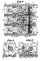
- Figure 3 is an enlarged, fragmentary, cross sectional view of the device of Figure 1 taken along line 3-3 of Figure 1;
- Figure 4 is an enlarge, perspective view of a pair of electrically insulated barrier indicator cards of the device of Figure 1;
- Figure 5 is an enlarged, cross sectional view of the device of Figure 1 taken along the line 5-5 of Figure 1, depicting the device in its CLOSED and BLOWN-OPEN positions; ,
- Figure 6 is an enlarged, fragmentary, cross sectional view of the device of Figure 1 taken along line 6-6 of Figure 5;
- Figure 7 is an enlarged fragmentary, cross sectional view of the device of Figure 1 taken along line 7-7 of Figure 5;
- Figure 8 is an enlarged, fragmentary, cross sectional view of the device of Figure 1 taken along line 8-8 of Figure 5;
- Figure 9 is an enlarged, fragmentary, cross sectional view of the cross-bar assembly of the device of Figure 1 taken along line 9-9 of Figure 8;
- Figure 10 is an enlarged fragmentary, cross sectional view of the cross-bar assembly of the device of Figure 1 taken along line 10-10 of Figure 8;
- Figure 11 is an enlarged, fragmentary, cross sectional view of the cross-bar and upper contact assembly of the device of Figure 1 taken along the line 11-11 of Figure 5;
- Figure 12 is an enlarged, fragmentary, cross sectional view of the cross-bar and upper contact assembly of the device of Figure 1 taken along the line 12-12 of Figure 11;
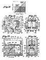
- Figures 12A and 12B are enlarged, fragmentary, cross sectional views of a portion of the upper contact assembly of the device of Figure 1, depicting sequential positions of the upper contact assembly during a BLOWN-OPEN operation;
- Figure 13 is an enlarged, exploded, perspective view of portions of the operating mechanism of the device of Figure 1;
- Figure 14 is an enlarged, fragmentary, cross sectional view of the center pole of phase of the device of Figure 1, depicting the device in its OPEN position;
- Figure 15 is an enlarged, fragmentary, cross sectional view of the center pole or phase of the device of Figure 1. depicting the device in its TRIPPED position;
- Figures 16 and 17 are enlarged, fragmentary, cross sectional views of the device of Figure 1 depicting sequential positions of the operating mechanism of the device of Figure 1 during a trip occurrence;
- Figure 18 is a force diagram illustrating the amount of handle force required to reset the device of Figure 1 as a function of handle travel;
- Figures 19, 20 and 21 are each enlarged, fragmentary, cross sectional views, similar to the view of Figure 12, depicting alternative embodiments of the cross-bar and upper contact assembly for the device of Figure 1;
- Figure 22 is an enlarged, fragmentary, cross sectional view of the assembly of Figure 21 taken along line 22-22 of Figure 21;
- Figure 23 is an enlarged, fragmentary, cross sectional view of an alternative embodiment of a lower contact for the device of Figure 1; and
- Figure 24 is an enlarged, fragmentary, cross sectional view of the lower contact of Figure 23 taken along line 24-24 of Figure 23.
- Figures 1-17 illustrate an improved molded
case circuit breaker 30 depicted as a three phase or three pole circuit breaker, the principles of the present invention disclosed herein are equally applicable to single phase or other polyphase circuit breakers and to both AC circuit breakers and DC circuit breakers. - The
circuit breaker 30 includes a molded, electrically insulating,top cover 32 mechanically secured to a molded, electrically insulating, bottom cover orbase 34 by a plurality offasteners 36. A plurality of first electrical terminals orline terminals load terminals 40A, 40B and 40C. These terminals are used to serially electrically connect thecircuit breaker 30 into a three phase electrical circuit for protecting a three phase electrical system. - The
circuit breaker 30 further includes an electrically insulating, rigid, manuallyengageable handle 42 extending through anopening 44 in thetop cover 32 for setting thecircuit breaker 30 to its CLOSED position (Figure 5) or to its OPEN position (Figure 14). Thecircuit breaker 30 also may assume a BLOWN-OPEN position (Figure 5, dotted line position) or a TRIPPED position (Figure 15). Subsequently moving to its TRIPPED position, thecircuit breaker 30 may be reset for further protective operation by moving thehandle 42 from its TRIPPED position (Figure 15) to and past its OPEN position (Figure 14). Thehandle 42 may then be left in its OPEN position (Figure 14) or moved to its CLOSED position (Figure 5), in which case thecircuit breaker 30 is ready for further protective operation. The movement of thehandle 42 may be achieved either manually or automatically by a mechanical actuator. Aposition indicator 46 provides an externally visually discernible indication of the condition or position of thecircuit breaker 30. Theposition indicator 46 is disposed about thehandle 42 and covers the bottom of theopening 44 to function as a mechanical and electrical barrier between the interior and exterior of thecircuit breaker 30. - As its major internal components (Figure 5), the
circuit breaker 30 includes a lowerelectrical contact assembly 50, a pair of upperelectrical contact members 52, anelectrical arc chute 54, aslot motor 56, and anoperating mechanism 58. Thearc chute 54 and theslot motor 56 are conventional, per se, and thus are not discussed in detail hereinafter. Briefly, thearc chute 54 is used to divide a single electrical arc formed between separatingelectrical contacts slot motor 56, consisting either of a series of generally U-shaped steel laminations encased in electrical insulation or of a generally U-shaped, electrically insulated, solid steel bar, is disposed about thecontact arms electrical contact arms electrical contacts electrical contacts arc chute 54 and theslot motor 56. - The lower electrical contact assembly 50 (Figures 5, 14 and 15) includes a lower, formed,
stationary member 62 secured to thebase 34 by afastener 64, a lowermovable contact arm 66, a limit orstop pin 68 fixedly secured to and movable with themovable contact arm 66, a lower contact biasing means orcompression spring 70, acontact 72 for physically and electrically contacting the upperelectrical contacts 238 and an electricallyinsulating strip 74 to reduce the possibility of arcing between the upperelectrical contact members 52 and portions of the lowerelectrical contact assembly 50. Theline terminal 38B extending exteriorly of thebase 34 comprises an integral end portion of the member 62 (Fig. 2). Thebase 34 includes. an upwardlyprotuberant portion 34A having an upper,inclined surface 34B that serves as a lower limit or stop for the movingcontact arm 66 during the rapid separation of theupper contact members 52 from thelower contact assembly 50. The lower, formedstationary member 62 includes alower portion 62A that engages thebase 34. Anaperture 62B is formed through thelower portion 62A for receiving the upwardly extendingbase portion 34A and for seating thecompression spring 70. Thelower portion 62A may also include a threadedaperture 62C formed therethrough for receiving thefastener 64 to secure thestationary member 62 and thus the lowerelectrical contact assembly 50 to thebase 34. Thestationary member 62 includes an upstanding, contactingportion 62D that may be integrally formed with or fixedly secured to thelower portion 62A. The stop pin 68 (FIG. 5) is provided for limiting the upward movement of themovable contact arm 66 upon physical engagement with the upstanding contactingportion 62D. - The
contact arm 66 is fixedly secured to arotatable pin 78 for rotation therewith on the upstanding contactingportion 62D about the longitudinal axis of therotatable pin 78. Effective conductive contact and current transfer is achieved between the lower formedstationary member 62 and the lowermovable contact arm 66 through therotatable pin 78. The lowermovable contact arm 66 includes an elongatedrigid lever arm 66A extending between therotatable pin 78 and thecontact 72 and a downwardly protuberant portion or spring locator 66B for receipt , within the upper end of thecompression spring 70 for maintaining effective physical interconnection between the lowermovable arm 66 and thecompression spring 70. Finally, the lowermovable contact arm 66 includes an integrally formed,flat surface 66C formed at its lower end for physically engaging thestop 34B to limit the downward movement of the lowermovable contact arm 66 and thecontact 72 fixedly secured thereto. - Each upper
electrical contact member 52 has acurrent contact 238 for physically and electrically contacting thecontact 72 of the lowerelectrical contact assembly 50 disposed at the end of an upper movableelongated contact arm 240. It is the passage of high level short circuit or fault current through the generallyparallel contact arms contact arms contacts strip 74 is used to electrically insulate theupper contact arms 240 from thelower contact arm 66. - The lower
electrical contact assembly 50 as described hereinabove utilizes the high magnetic repulsion forces generated by high level short circuit or fault current flowing through the elongated parallel portions of theelectrical contact arms contact arm 66 against the bias of the compression spring 70 (Fig. 5). An extremely rapid separation of theelectrical contacts electrical contacts electrical contact assembly 50 further eliminates the necessity for utilizing flexible copper shunts used in many prior are molded case circuit breakers for providing a current carrying conductive path between a terminal of the circuit breaker and a lower movable contact arm of a lower electrical contact. - The operating mechanism 58 (Figs. 5, 13 and 16) includes an
over-center toggle mechanism 80; an electronic or thermal-magnetic trip mechanism 82 (not shown in detail); an integral or one-piece molded cross-bar 84 (Fig. 13); a pair of rigid, opposed or spaced apart,metal side plates 86; a rigid, pivotable, metal handleyoke 88; arigid stop pin 90; and a pair of operating tension springs 2. - The
over-center toggle mechanism 80 includes a rigid, one-piece metal cradle 96 that is rotatable about the longitudinal axis of acradle support pin 98. The opposite longitudinal ends of thecradle support pin 98 in an assembled condition are retained in a pair ofapertures 100 formed through theside plates 86. - The
toggle mechanism 80 further includes a pair of upper toggle orkicker links 102, a pair oflower toggle links 104, atoggle spring pin 106 and an upper togglelink follower pin 108. Thelower toggle links 104 are secured to the upperelectrical contact members 52 by atoggle contact pin 110. Each of thelower toggle links 104 includes alower aperture 112 for receipt therethrough of thetoggle contact pin 110. Thetoggle contact pin 110 also passes through anaperture 114 formed through each of the upperelectrical contact members 52 enabling the upperelectrical contact members 52 to freely rotate about the central longitudinal axis of thepin 110. The opposite longitudinal ends of thepin 110 are received and retained in the cross-bar 84 (Fig. 6). The movement of thelower toggle links 104 causes the movement of the cross-bar 84 and the corresponding movement of the upperelectrical contact members 52 under other than high level short circuit or fault current conditions. In this manner, movement of the upperelectrical contact members 52 in the center pole or phase of thecircuit breaker 30 by theoperating mechanism 58, simultaneously, through the rigid cross-bar 84, causes the same movement in the upperelectrical contact members 52 associated with the other poles or phases of thecircuit breaker 30. - Each of the
lower toggle links 104 also includes anupper aperture 116; and each of the. upper toggle links 102 includes anaperture 118. Thetoggle spring pin 106 is received through the apertures l16 and 118, thereby interconnecting the upper andlower toggle links pin 106 includejournals 120 for the receipt and retention of the lower, hooked orcurved ends 122 of thesprings 92. The upper, hooked orcurved ends 124 of thesprings 92 are received through and positioned inslots 126 formed through an upper, planar orflat surface 128 of thehandle yoke 88. A locatingpin 130 is transversely disposed across theslots 126 for retaining the curved ends 124 of thesprings 92 in engagement with the handle yoke 88 (Fig. 7). - In an assembled condition, the disposition of the curved ends 124 within the
slots 126 and the disposition of the curved ends 122 in thejournals 120 retain thelinks pin 106 and also maintain thesprings 92 under tension, enabling the operation of theover-center toggle mechanism 80 to be controlled by and responsive to external movements of thehandle 42. - The upper links 102 (Fig. 13) also include a recess or groove 132 which mates with a pair of spaced apart
journals 134 formed along the length of thepin 108. The center portion of thepin 108 is configured to be fixedly received in anaperture 136 formed through thecradle 96 at a location spaced by a predetermined distance from the axis of rotation of thecradle 96 coincident with the longitudinal axis of thepin 98. The spring tension from thesprings 92 retains the upper toggle links 102 in engagement with thepin 108. The rotational movement of thecradle 96 effects a corresponding movement or displacement of the upper portions of thelinks 102 as is described hereinafter. - The
cradle 96 includes anelongated surface 140 having a generallyflat latch surface 142 formed therein. Thesurface 142 is configured to engage a pivotable lever or trip arm 144 (Figs. 5, 16 and 17) of thetrip mechanism 82. Thetrip arm 144 pivots about astationary pin 145 of thetrip mechanism 82 upon a trip operation initiated by thetrip mechanism 82. Thetrip mechanism 82 is an electronic or thermal-magnetic trip mechanism that is capable of detecting both low level short circuit or overload current conditions and high level short circuit or fault current conditions. Upon the detection of any such condition thetrip mechanism 82 rotates thetrip arm 144 about thepivot pin 145 to initiate a trip operation of the operating mechanism 58 (Figs. 16 and 17). - The
cradle 96 also includes a curved,elongated cam surface 148 for contacting a cradle cam orlimit pin 150. The opposite longitudinal ends of thecam pin 150 are received and retained in a pair ofgrooves 152 formed in thehandle yoke 88, to enable, in the preferred embodiment, the rotation of thepin 150 within thehandle yoke 88. Thecradle 96 further includes a generallyflat stop surface 154 for contacting a central portion orrigid stop 156 of thestop pin 90. The engagement of thesurface 154 with therigid stop 156 limits the movement of thecradle 96 in a counterclockwise direction subsequent to a trip operation (Figs. 15 and 17). - During a trip operation, the lines of action of the operating springs 92 are changed, resulting in the movement of the
handle 42 to a TRIPPED position (Fig. 15), intermediate the CLOSED position (Fig. 5) and the OPEN position (Fig. 14) of thehandle 42, to indicate that thecircuit breaker 30 has tripped. The engagement of thestop surface 154 andrigid stop 156 limits the movement of thecradle 96 and thereby locates thehandle 42 in the TRIPPED position (Fig. 15) through the engagement of thepin 150 with thecam surface 148 of thecradle 96. In addition, the camming engagement of thecam surface 148 androtatable pin 150 resets theoperating mechanism 58 subsequent to a trip operation as thecradle 96 moves in a clockwise direction against the bias of the operating springs 92 from its TRIPPED position (Fig. 15) to and past its OPEN position (Fig. 14), thereby relatching thelatch surface 142 and thetrip arm 144. The cam surface l48 is configured to increase the mechanical advantage of thehandle 42 in a predetermined manner in accordance with the specific design or contour of thecam surface 148 as thesprings 92 are extended during a reset operation. In this manner only a comparatively low and substantially constant reset force applied to thehandle 42 is required to achieve the resetting of theoperating mechanism 58 after a trip operation and to move thehandle 42 between its TRIPPED and OPEN positions. - The force diagram of FIG. 18 illustrates handle travel during a reset operation from a TRIPPED (0) position to a RESET (1) position relative to the reset force required to move the
handle 42. The NORMAL RESET line illustrates the force required in conventional or prior art circuit breakers having cradles without the contouredcam surface 148 in thecradle 96 to overcome the increasing bias of one or more operating springs as a handle is moved during a reset operation. The CONSTANT FORCE RESET line illustrates the substantially constant reset force required to be applied through thehandle 42 to thepin 150 and thecam surface 148 of thecradle 96 to achieve a reset operation. As is apparent, the peak force required during such a reset operation of theoperating mechanism 58 having thecradle 96 with the contouredcam surface 148 is substantially reduced from the peak force required in circuit breakers having conventional cradles. The work done during such reset operations corresponds to the areas under the NORMAL RESET line and the CONSTANT FORCE RESET line. The total work done during the reset operation is the same for both the NORMAL RESET line and the CONSTANT FORCE RESET line. However, the reduction in the peak force required for a reset operation by the use of acradle 96 having acam surface 148 contoured in a predetermined manner as described hereinabove and as depicted in the drawing enables the use of a motor operator or actuator with a peak power rating corresponding to the comparatively low constant force depicted in Fig. 18 required to move thehandle 42. - The engagement of the
cam surface 148 ofcradle 96 andpin 150 during a reset operation occurs as follows. During a reset operation subsequent to a trip operation, as thehandle 42 is moved clockwise from the TRIPPED position (Fig. 15) to and oast the OPEN position (Fig. 14), a moment about the longitudinal axis of thecradle support pin 98 occurs due to the application of handle force through thecam pin 150 to thecam surface 148 that substantially counteracts the bias of the operating springs 92. The moment about the longitudinal axis of the pin 93 increases as thepin 150 moves along thesurface 148 proportionally to the increase in the distance between the longitudinal axis of thepin 98 and the location of engagement of thepin 150 on thesurface 148 that is, the moment arm. Additionally,cam surface 148 is contoured in a predetermined manner to further increase the mechanical advantage of thehandle 42 as the handle '42 is moved during the reset operation. During the initial movement of thehandle 42, thesurface 148 is contoured at a relatively steep angle with respect to the distance between thecam pin 150 and the rotatablecradle support pin 98 since a relatively small force is required to overcome the bias of thesprings 92. As thehandle 42 is moved further during the reset operation thecam surface 148 is comparatively less steeply contoured providing increased mechanical advantage to thehandle 42 to overcome the increased bias of the extended springs 92. This increased mechanical advantage enables a substantially constant reset force to be applied through thehandle 42 throughout the reset operation (Fig. 18). - The
toggle mechanism 80 includes a pair of rigid, spaced-apart, stationary, pivot-transfer links 158 (Figs. 5, 13, 16 and 17) that are fixedly secured to thestop pin 90. Thestationary links 158 include an elongated,lower surface 160 spaced from anelongated surface 162 formed on the upper toggle links 102. Eachstationary link 158 further includes a recess or groove 164 configured for receiving the rotatablecradle support pin 98. Themetal side plates 86 includeapertures 166 for receiving and retaining the opposite longitudinal ends of thestop pin 90. - The
stationary links 158 and thelinks operating mechanism 58 even with thehandle 42 physically restricted or obstructed in the CLOSED position, ensuring that the upperelectrical contacts 238 are moved out of engagement with the lowerelectrical contacts 72 upon the initiation of a trip operation by thetrip mechanism 82. When thehandle 42 is in a CLOSED position (Fig. 16), a pair of first or initial pivot points 163 at the ends of thesurfaces 162 of theupper links 102 engage thesurfaces 160 of thelinks 158 near thegrooves 164 of thelinks 158. During a trip operation, thecradle 96 is unlatched by the clockwise rotational movement of thetrip arm 144, resulting in the counterclockwise rotation of thecradle 96. Theupper links 102 are rotated counterclockwise by thesprings 92 about thefirst pivot point 163. Thesprings 92 also move thetoggle spring pin 106 in a clockwise direction about thepin 110, resulting in corresponding movements of thelinks 104, theupper contact members 52 and the cross-bar 84. Subsequently, thesurfaces 162 of thelinks 102 physically engage thesurfaces 160 of thelinks 158 and, thereafter, the pivot points are transferred from the initial pivot points 163 to a pair of second pivot points 168, resulting in the increased rotational velocity of theupper contact members 52. - The pivot-transfer system as disclosed herein exhibits a significant mechanical advantage to move the
upper links 102 about the first or initial pivot points 163 during the initial counterclockwise rotation of theupper links 102 upon the occurrence of a trip condition and thereby to overcome inertia and to cause the rapid separation of the upper andlower contacts electrical contact members 52 to rapidly lengthen the electrical arc betweencontacts - The
handle yoke 88 includes a pair of downwardly depending support arms 176 (FIG. 13). A pair of bearing surfaces or roundedtabs 178 are formed at the lowermost extremities of the downwardly dependingsupport arms 176 of thehandle yoke 88 for engagement with bearing or pivot surfaces 180 formed in theside plates 86. Thehandle yoke 88 is thus controllably pivotable about the bearing surfaces 178 and 180. Theside plates 86 also include bearingsurfaces 182 for contacting round bearingsurfaces 186 of the cross-bar 84 and for retaining the cross-bar 84 securely in position within thebase 34. Each of theside plates 86 includes a pair of downwardly dependingsupport arms 188 that terminate in elongate, downwardly projecting stakes ortabs 190 for securely retaining theside plates 86 in thecircuit breaker 30. In assembling thesupport plate 86 in thecircuit breaker 30, thetabs 190 are passed throughapertures 191 formed through the base 34 (Fig. 6). Thetabs 190 may then be mechanically deformed, for example, by peening, to lock thetabs 190 in engagement with thebase 34. A pair of formed electrically insulating barriers 192 (FIG. 7) is used to electrically insulate conductive components and surfaces in one pole or phase of thecircuit breaker 30 from conductive components or surfaces in adjacent poles or phases of thecircuit breaker 30. - The integral or one-piece molded cross-bar 84 includes three
enlarged sections 194 separated by the round bearing surfaces 186. A pair of peripherally disposed, outwardly projectinglocators 196 are provided to retain the cross-bar 84 properly located within thebase 34. Thebase 34 includes a plurality of bearing surfaces 198 (FIG. 7) complementarily shaped to the bearing surfaces 186 for seating the cross-bar 84 for rotational movement in thebase 34. Thelocators 196 are received within arcuate recesses orgrooves 200 formed along thesurfaces 198. Eachenlarged section 194 further includes a pair of spaced-apart anertures 202 (FIG. 13) for receiving thetoggle contact pin 110. Thepin 110 may be retained within theapertures 202 by any suitable means, for example, by an interference fit therebetween. Eachenlarged section 194 also includes anopening 204 formed therein for receipt of one longitudinal end orbase portion 206 of each of the upperelectrical contact members 52. - The
obening 204 also permits the receipt and retention of a pair of contact arm compression springs 208 (FIGS. 11 and 13) and an associated, formed,spring clip 210. The compression springs 208 are retained in position by being disposed within a pair of spaced-apartrecesses 212 formed therein. Thespring clip 210 is configured to be disposed between the compression sorings 208 and thebase portions 206 of the upperelectrical contact members 52 to transfer the compressive force from thesprings 208 to thebase portions 206, thereby ensuring that the upperelectrical contact members 52 and the cross-bar 84 move in unison in response to the operation of theoperating mechanism 58 during a normal trip operation. However, upon the occurrence of a high level short circuit or fault current condition, the upperelectrical contact members 52, responding to the repulsion forces generated between theparallel contact arms pin 110, overcoming the bias forces of thespring 208 and thespring clip 210, thus enabling theelectrical contacts operating mechanism 58 to sequence. This independent movement of each of the upperelectrical contact members 52 under the above high fault condition is possible in any pole or phase of thecircuit breaker 30. - The spring clip 210 (Fig. 12) includes a lower
formed portion 214 having an upper tab portion 215 (Fig. 13) and anupstanding end portion 217 for engagement with a complementarily shapedportion 216 of theenlarged section 194 of the cross-bar 84 to properly locate and retain thespring clip 210 in engagement with theenlarged section 194. Thespring clip 210 includes a pair of upwardly extendinglegs 218 for engagement with the compression springs 208. Each upwardly extendingleg 218 includes an outwardly projectingsurface 220. Theterminal portion 206 of eachupper contact arm 240 includes a generally C-shaped slot ordetent 222 formed in an arcuately shapedsurface 224 thereof. Thedetent 222 and thesurface 220 are configured to provide a predetermined, variable amount of compressive force therebetween. - During normal operating conditions, the
surfaces 220 of thespring clip 210 contact thesurfaces 224 of theupper contact arms 240 at the detents or steep cam surfaces 222 thereof to retain the cross-bar 84 in engagement with the upper electrical contact members 52 (Figs. 5 and 12). Upon the occurrence of a high level short circuit or fault current condition, as eachupper contact arm 240 rotates in a clockwise direction about the longitudinal axis of thepin 110, eachsurface 224 moves along thesurface 220. The resultant line of force of thespring 208 through the engagingsurfaces pin 110 as the upperelectrical contact members 52 rotate to their BLOWN-OPEN position (Figs. 5 and 12), thereby substantially decreasing the compression moment of thesprings 208 about the longitudinal axis of thepin 110. Subsequently, when thecircuit breaker 30 is reset to its CLOSED position, thearcuate cam surface 224 is moved against thesurface 220 to the latch point at thedetent 222. By changing the configuration of thedetent 222 or the configuration of thecam surface 220 of thespring clip 210, the compression moment arm ofsprings 208 can be increased or decreased as desired. - Referring to Figs. 12A and 12B, the
base portion 206 of the upperelectrical contact members 52 is shown in its CLOSED position (Fig. 12A) and in a sequential position (Fig. 12B) during a BLOWN-OPEN operation. The compressive force of thespring 208 is illustrated in Figs. 12A and 12B by an arrow at the point of engagement of the surfaces 220 (Fig. 12) and 224 and is designated with a reference character F. In the CLOSED position, a component force Fl is directed along a line normal to the tangent of thesurface 224 at the point of engagement of thesurfaces pin 110 by a distance shown as Ll. The compression moment of the component spring force Fl with the moment arm Ll is provided to ensure that the upperelectrical contact members 52 and the cross-bar 84 move in unison in response to the operation of theoperating mechanism 58 during a normal trip operation. During a BLOWN-OPEN operation as the upperelectrical contact members 52 rotate about the longitudinal axis of the pin 110 (Fig. 12B), thesurface 224 is configured to provide a component force F2 of thesprings 208 that passes substantially through or close to the pivot ofmembers 52 or the the longitudinal axis of thepin 110 to reduce the moment arm to substantially zero. The compression moment of thespring 208 about the longitudinal axis of thepin 110 is substantially reduced thereby ensuring that the upperelectrical contact members 52 move independently of the cross-bar 84 to rapidly separate theelectrical contacts base portions 206 into driving engagement with the cross-bar 84 for enabling rotational movement of theupper contact members 52 in unison with the rotational movement of thecross bar 84 and for enabling rotational movement of the upperelectrical contact member 52 substantially independently of thecross bar 84 upon the occurrence of a fault current condition during a BLOWN- , OPEN operation. - Two pairs of flexible
current shunts 234, as illustrated in Fig. 13, are used to provide a current carrying electrical path through thecircuit breaker 30. Each pair offlexible shunts 234 is connected by any suitable means, for example, by brazing, to the opposite sides of thelongitudinal end portion 206 of each upperelectrical contact member 52 and to a lowerconductive plate 236 in thetrip mechanism 82. Theflexible shunts 234 provide the current carrying electrical path between the upperelectrical contact members 52 and thetrip mechanism 82 and thereby through thecircuit breaker 30 between theterminals 38B and 40B via the lowerelectrical contact assembly 50, the upperelectrical contact members 52, theflexible shunts 234 and thetrip mechanism 82. - In operation, the
circuit breaker 30 may be interconnected in a three phase electrical circuit via line and load connections to theterminals 38A, B and C and 40A, B and C.The operating mechanism 58 may be set by moving thehandle 42 from its TRIPPED position (Fig. 15) as far as possible past its OPEN position (Fig. 14) to ensure the resetting of thelatch surface 142 of thecradle 96 and tilepivotable trip arm 144. - Subsequent to a trip operation, a force is applied to the
handle 42 to move thehandle 42 clockwise from its TRIPPED position (Fig. 15) to and past its OPEN position (Fig. 14) to enable relatching of thelatch surface 142 of thecradle 96 with thetrip arm 144. During such movement of thehandle 42, thecam pin 150 engages thecam surface 148 of thecradle 96 and moves thecradle 96 clockwise about the rotatablecradle support pin 98. The clockwise rotation of thecradle 96 results in a corresponding movement of the togglelink follower pin 108 that is fixedly retained within thecradle 96. During such movement, the operating springs 92 rotate clockwise about thetoggle spring pin 106 and exert an upward force on thetoggle spring pin 106; thekicker links 102 rotate counterclockwise about the upper togglelink follower pin 108 and thelower toggle links 104 are rotated clockwise about the pin 110 that is held in a stationary position within the cross-bar 84. The upward spring force exerted on thetoggle spring pin 106 is also applied through thekicker links 102 to thepin 108, thereby providing a counterclockwise biasing force to thecradle 96 about the longitudinal axis of thecradle support pin 98. Thehandle 42 is moved clockwise past the OPEN position shown in Fig. 14 until thelatch surface 142 relatches with thetrip arm 144. Thehandle 42 may then be moved from its OPEN position (Fig. 14) to its CLOSED position (Fig. 5) causing theoperating mechanism 58 to close thecontacts circuit breaker 30 is then ready for operation in protecting a three phase electrical circuit. - The
handle 42 is moved from its OPEN position to its CLOSED position by applying a force to thehandle 42 to cause the counterclockwise movement thereof. In the OPEN position, thecradle 96 is provided in its latched position with thelatch surface 142 engaging thepivotal trip arm 144 and thegrooves 132 of the upper toggle links 102 are retained in engagement with the upper togglelink follower pin 108 that is fixedly received within, thecradle 96. During the initial counterclockwise movement ofhandle 42, the lines of action of the operating springs 92 are to the right to the upper togglelink follower pin 108; the kicker links 102, thelower toggle links 104 and thetoggle spring pin 106 are then stationary. As the line of action of the operating springs 92 is moved past the upper togglelink follower pin 108, thekicker links 102 rotate clockwise until thepivot 163 engages thesurface 160 of thestationary links 158. Additionally, as a result of the change in the line of action of the operating springs 92 moving past thepin 108, thetoggle spring pin 106 rotates clockwise about the upper togglelink follower pin 108 and moves to the left, resulting in the movement of thelower toggle link 104 which rotates counterclockwise about thetoggle spring pin 106. Thereby, the cross-bar 84 is rotated counterclockwise and the corresponding movement of theelectrical contact members 52 effects the closing of thecontacts operating mechanism 58 in the CLOSED position. - Upon the occurrence of a sustained overload condition, the
pivotable trip arm 144 pivots about thestationary pin 145 to unlatch thelatch surface 142 of thecradle 96. Thecradle 96 is immediately accelerated by the operating springs 92 through thekicker links 102 for rotation in the counterclockwise direction resulting in the substantially instantaneous movement of the upper toggle links 102, thetoggle spring pin 106 and thelower toggle links 104, as illustrated in dotted line in Fig. 16. The upward movement of thepin 106 results in a corresponding upward movement of thetoggle contact pin 110 through the movement of thelower toggle links 104, and the immediate, upward movement of the rotatable cross-bar 84 effecting the upward movement of the upperelectrical contact members 52 to their TRIPPED position (Fig. 15). Since thebase portions 206 of the upperelectrical contact members 52 are biased into engagement with the cross-bar 84 through thesprings 208, the upperelectrical contact members 52 move in unison with the cross-bar 84, resulting in the simultaneous or synchronous separation of all three of the pairs of upperelectrical contacts 72 from the lowerelectrical contacts 238 in thecircuit breaker 30. During this trip operation, any electrical arc that may have been present across thecontacts - Upon the occurrence of a high level short circuit or fault current condition and as a result of the large magnetic repulsion forces generated by the flow of fault current through the generally
parallel contact arms electrical contacts contact arm 66 of the lowerelectrical contact assembly 50 is limited by thestop surface 34B, and movement of eachcontact arm 240 of each upperelectrical contact member 52 is limited by the engagement of a lower contacting surface 242 (Fig. 12) of theterminal portion 206 of thecontact arm member 52 and astop surface 244 formed in the base. Eachcontact arm 240 is held in its BLOWN-OPEN position by the engagement of thesurfaces electrical contacts - The position indicator 46 (Figs. l, 3-5 and 14-17) of the
circuit breaker 30 provides an externally visually discernible indication of the condition or position of theoperating mechanism 58 of the circuit breaker. Theposition indicator 46 includes a plurality of insulating cards, strips or barriers, for example, as specifically illustrated, a first or upper electrically insulating card, strip orbarrier 246 and a second or lower electrically insulating card, strip orbarrier 248 that cooperate to provide an external, clear indication of the position or condition of theoperating mechanism 58. Thebarriers handle 42 and cover the bottom of theopening 44 to function as a mechanical and electrical barrier between the interior and exterior of thecircuit breaker 30. Preferably, thetop cover 32 includes a pair of spaced apart, laterally aligned openings orviewing slots 250 formed therethrough to provide external visual access to either a pair of spaced apart, laterally aligned position indicia or red markings 252 (Fig. 4) fixedly secured to, or on, thebarrier 246 or a pair of spaced apart, laterally aligned position indicia orwhite markings 254 fixedly secured to, or on, thebarrier 246 or a pair of spaced apart, laterally aligned position indicia orgreen markings 256 fixedly secured to, or on, the upper surface of thebarrier 248. - The
barrier 246 has a relativelysmall slot 258 that fits securely about thehandle 42. Thebarrier 248 has, comparatively, a muchlarger slot 260 that enables relative movement between thebarriers barrier 248 and thehandle 42. Thebarrier 248 also is dimensionally longer along the longitudinal axis of theopening 44 than thebarrier 246 in order to ensure that thegreen markings 256 may be externally visually discerned when aligned with theviewing slots 250 and to ensure that theopening 44 is covered in all positions of thehandle 42. - When the
handle 42 is moved in the open :g 44 to its ON or CLOSED position, thered markings 252 are positioned in theviewing slots 250 to provide an externally visually discernible indication that theoperating mechanism 58 of thecircuit brearer 30 is in its CLOSED position (Fig. 5). Upon a trip operation of thecircuit breaker 30, thehandle 42 moves to the load side of the circuit breaker 30 (Fig. 15). Thebarrier 246, captured about thehandle 42, moves with thehandle 42 to position thewhite markings 254 in theviewing slots 250, providing an externally visible indication that the operating mechanism of thecircuit breaker 30 is in its TRIPPED position (Fig. 15). During this movement of thehandle 42 thelower barrier 248 is not moved as thehandle 42 moves within theslot 260 . When thehandle 42 is moved to its OFF or OPEN position in theopening 44, thebarrier 246 is moved beyond theviewing slots 250 and thegreen markings 256 on thebarrier 248 are positioned in theviewing slots 250 to provide an external visually discernible indication that theoperating mechanism 58 is in its OPEN position. - A plurality of spaced apart insulating support members 262 (Figs. 3 and 5), preferably integrally formed portions of the
top cover 32, is used to provide lateral support of the longitudinal end of thebarrier 248 when thehandle 42 is in its OPEN position in order to prevent substantial internal deflection of thebarrier 248 upon the application of an external force. The use of the twobarriers colored markings handle 42 and thebarrier 248 enables ashorter barrier 248 to be used than would be required in the absence of the lost motion connection. - In accordance with an alternative embodiment (Fig. 19) of the
circuit breaker 30, identical reference characters as used hereinabove with respect to Figs. 1-17 are employed hereinafter to describe unchanged portions and common components of thecircuit breaker 30, each of a pair of upperelectrical contact members 264 includes a longitudinal end orbase portion 266. Theterminal portions 266 include a lower groove ordetent 268 and an upper groove or detent 270 formed along anarcuate surface 272 thereof. Aspring clip 274 is disposed between a pair of compression springs 276 and thebase portions 266 of the upperelectrical contact members 264 to transfer to transfer the compressive force from thesprings 276 to tilebase portions 266, thereby ensuring that the upperelectrical contact members 264 and the cross-bar 84 move in unison in response to movement of thehandle 42 or the operation of theoperating mechanism 58 during a normal trip operation. Thespring clip 274 includes an outwardly projectingsurface 278 formed in each of theupstanding legs 218 for engaging thearcuate surfaces 272 of thebase portions 266 of the upperelectrical contact members 264. As described hereinbefore with respect to Figs. 12A and 12B, thelower detents 268 and thesurfaces 278 are configured to provide a compression moment of the component force Fl about the longitudinal axis of thepin 110 proportional to the distance Ll between the longitudinal axis of thepin 110 and the resultant line of force of thespring 212 through the engagingsurfaces surface 272. Thesprings 212 releasably bias thebase portions 242 of theupper contact members 264 into driving engagement with the cross-bar 84 enabling rotational movement ofmembers 264, in unison with the cross-bar 84 and enabling rotational movement of themembers 264 substantially independently of the cross-bar 84 upon the occurrence of a fault current condition during a BLOWN-OPEN operation. The frictional force F2 (Fig. 12B) passes substantially through the longitudinal axis of thepin 110 and is significantly less than Fl (Fig. 12A), as is described hereinbefore. - During normal operating conditions, the
surface 278 of thespring clip 274 contacts thelower detent 268 of the upperelectrical contact members 264 to retain the cross-bar 84 in driving engagement with the upperelectrical contact members 264. Upon the occurrence of a high level short circuit or fault current condition, as the upperelectrical contact members 264 rotate in a clockwise direction about the longitudinal axis ofpin 110, thearcuate surface 272 of thebase portion 266 is moved against thesurface 278. The resultant line of force of thespring 212 through the engagingcam surfaces pin 110 as the upperelectrical contacts 264 rotate to their BLOWN-OPEN position (Fig. 19, in dotted line), thereby substantially reducing the moment imparted by thesprings 276 about the longitudinal axis of thepin 110. The upper detent 270 engages the outwardly projectingsurface 278 of thespring clip 274 in the BLOWN-OPEN position to retain the upperelectrical contact members 264 in their BLOWN-OPEN position, thereby eliminating or minimizing the possibility of contact restrike. - In accordance with a further alternative embodiment (Fig. 20) of the
circuit breaker 30, each of a pair of upperelectrical contact members 280 includes a longitudinal end orbase portion 282. Theportion 282 includes a lower groove ordetent 284 and an upper groove ordetent 286 formed along anarcuate surface 288 thereof. - A
ball 290 is disposed between thearcuate surface 288 of eachbase portion 282 and one of a pair of compression springs 292 that are retained within a cross-bar 294. An adjusting screw or threadedplug 296 engages thecompression spring 292 to provide a desired spring force on theball 290. Theballs 290 transfer the compressive force from thesprings 292 to thebase portions 282, thereby ensuring that the upperelectrical contact members 280 and the cross-bar 294 move in unison in response to movement of thehandle 42 or the operation of theoperating mechanism 58 during a normal trip operation. During normal operating conditions, theball 290 engages thelower detent 284 of the upperelectrical contact members 280 and transfers the compressive spring force thereto. - Upon the occurrence of a high level short circuit or fault current condition, as the upper
electrical contact members 280 rotate in a clockwise direction about the longitudinal axis ofpin 110, thearcuate surfaces 288 of thebase portions 282 are moved against theballs 290. As described hereinbefore with respect to Figs. 12A and 12B, the component force of thesprings 292 is significantly reduced from F1 with the moment arm Ll in the CLOSED position to frictional force F2 that passes substantially through the pivot ofmembers 280 or the longitudinal axis ofpin 110 in the subsequent position as the upperelectrical contact members 280 rotate about the longitudinal axis of thepin 110 during a BLOWN-OPEN operation. Theupper detents 286 engage theballs 290 in the BLOWN-OPEN position, holding thecontact members 280 in their BLOWN-OPEN position, thereby eliminating or minimizing the possibility of contact restrike. Subsequently, when thecircuit breaker 30 is reset to its CLOSED position, thearcuate surfaces 288 are moved against theballs 290 until theballs 290 are disposed in thelower detents 284. - In accordance with another alternative embodiment (Figs. 21 and 22) of the
circuit breaker 30, each of a pair of upperelectrical contact members 298 includes a longitudinal end orbase portion 300 having a lower groove ordetent 302 and and an upper groove ordetent 304 formed along anarcuate surface 306. Ametal leaf spring 308 is secured to a molded cross-bar 310 by a fastener 312 and is disposed between thebase portions 300 of the upperelectrical contact members 298 and the cross-bar 310. Theleaf spring 308 includes an upper, generallyflat portion 314 that engages the cross-bar 310 and that has an aperture (not illustrated) formed therethrough for receiving the fastener 312 to secure theleaf spring 308 to the cross-bar 310. Theleaf spring 308 further includes a pair of downwardly dependingarms 316 with lower, integrally formed, laterally extending portions 318 thereof. Each lower portion 318 includes an outwardly projectingsurface 320 formed thereon. Theleaf spring 308 is configured to be disposed about the cross-bar 310 with the cam surfaces 320 thereof provided in contacting engagement with thearcuate surfaces 306 of thebase portions 300 of the upperelectrical contact members 298. Theleaf spring 308 is formed to provide a predetermined spring force to thebase portions 300 to ensure that the upperelectrical contact members 298 and the cross-bar 310 move in unison in response to movements of thehandle 42 and of theoperating mechanism 58 during a normal trip operation. - During normal operation, the
surfaces 320 of theleaf spring 308 engage thelower detents 302 of thebase portions 300. Upon the occurrence of a high level short circuit or fault current condition, the upperelectrical contact members 298 rotate about thepin 110 and thesurfaces 306 move along thesurfaces 320 of theleaf spring 308 enabling, theelectrical contacts operating mechanism 58 to sequence. As described hereinbefore with respect to Figs. 12A and 12B, the component force of theleaf spring 308 is significantly reduced from Fl with the moment arm Ll in the CLOSED position to the frictional force F2 that passes substantially through the pivot ofmembers 298 or thelongitudinal axis pin 110 in the subsequent position as the upperelectrical contact members 298 rotate about the longitudinal axis of thepin 110 during a BLOWN-OPEN operation. Theupper detents 304 engage thesurfaces 320 to retain the upperelectrical contacts 298 in their BLOWN-OPEN position, thereby eliminating or minimizing the possibility of contact restrike. Theleaf spring 308 provides sufficient spring force to ensure proper contacting engagement between the upperelectrical contact members 298 and the cross-bar 310 without the necessity for one or more compression springs. - In accordance with a further alternative embodiment (Figs. 23 and 24) of the
circuit breaker 30, a lowerelectrical contact assembly 322 includes a lower, formed,stationary member 324 that engages thebase 34, an upstanding contactingportion 326, a lowermovable contact arm 328, a lower contact biasing means ortorsion spring 330, acontact 332 for physically and electrically contacting the upperelectrical contact 238 and an electrically insulatingstrip 334 to reduce the possibility of arcing between the upperelectrical contact member 52 and portions of the lowerelectrical contact assembly 322. Themovable contact arm 328 is fixedly secured to therotatable pin 78 for rotation therewith on the upstanding contactingportion 326 about the longitudinal axis of therotatable pin 78. Themovable contact arm 328 includes an inclined,elongated surface 336 having a recess or groove 338 formed at one end thereof. Themovable contact arm 328 further includes an integrally formed, generally flat, limit surface 340 formed at one end for contacting thestop 34B to limit the downward movement of themovable contact arm 328 and thecontact 332 fixedly secured thereto. - The
torsion spring 330 includes an upperelongated spring arm 342 for engaging thesurface 336 and a pair of spaced-apart, elongated, downwardly extendingsupport arms 337 terminating in a pair ofcoil extensions 344 for securely retaining thecontact spring 330 in thecircuit breaker 30. In assembling the lowerelectrical contact assembly 322 in thecircuit breaker 30, theextensions 344 are passed through a pair ofapertures 346 formed through the lower formedstationary member 324; and thelegs 344 may then be mechanically deformed to lock thespring 330 in engagement with thestationary contact member 324. Thetorsion spring 330 is configured as described herein and as depicted in the drawing to provide the required spring force to ensure that the lowerelectrical contact 322 is properly biased into engagement with the upperelectrical contact 52 and to provide reliable operation over an extended period of time. - As described hereinabove with respect to the lower
electrical contact assembly 50, thecontact assembly 322 utilizes the high magnetic repulsion forces generated by high level short circuit or fault current flowing through the elongated parallel portions of theelectrical contact arms contact arm 328 against the bias of thecontact spring 330. - Upon the occurrence of a high level short circuit or fault current condition, the
movable contact arm 328 rotates in a counterclockwise direction about the longitudinal axis of thepin 78 and is downwardly deflected; and thespring arm 342 of thespring 330 moves along thesurface 336 of themovable contact arm 328. The downward deflection of themovable contact arm 328 is limited by the engagement of the flat surface 340 of thecontact arm 328 with thestop 34B. The angle of inclination of theinclined surface 336 effectively reduces the spring force applied to themovable contact arm 328 after the upper andlower contacts contact 322 during a fault current condition. In addition, the moment arm of the spring force, applied by thespring arm 342, about the axis of thepin 78 is reduced while, simultaneously, the mechanical advantage of the above-mentioned high magnetic repulsion forces increases as thespring arm 342 moves along thesurface 336 in the direction of thepin 78. Consequently, the resultant force opposing the downward movement of thecontact 322 during a fault current condition is substantially reduced.
Claims (12)
Applications Claiming Priority (2)
| Application Number | Priority Date | Filing Date | Title |
|---|---|---|---|
| US756484 | 1985-07-18 | ||
| US06/756,484 US4642430A (en) | 1985-07-18 | 1985-07-18 | Molded case circuit breaker with an improved contoured cradle |
Publications (3)
| Publication Number | Publication Date |
|---|---|
| EP0209054A2 true EP0209054A2 (en) | 1987-01-21 |
| EP0209054A3 EP0209054A3 (en) | 1988-01-13 |
| EP0209054B1 EP0209054B1 (en) | 1992-01-29 |
Family
ID=25043692
Family Applications (1)
| Application Number | Title | Priority Date | Filing Date |
|---|---|---|---|
| EP86109300A Expired - Lifetime EP0209054B1 (en) | 1985-07-18 | 1986-07-08 | Molded case circuit breaker |
Country Status (15)
| Country | Link |
|---|---|
| US (1) | US4642430A (en) |
| EP (1) | EP0209054B1 (en) |
| JP (1) | JPH0821302B2 (en) |
| KR (1) | KR940001119B1 (en) |
| CN (1) | CN1007945B (en) |
| AU (1) | AU583133B2 (en) |
| BR (1) | BR8603667A (en) |
| CA (1) | CA1283434C (en) |
| DE (1) | DE3683698D1 (en) |
| ES (1) | ES8800508A1 (en) |
| IN (1) | IN167161B (en) |
| MX (1) | MX163210B (en) |
| PH (1) | PH22768A (en) |
| SG (1) | SG129693G (en) |
| ZA (1) | ZA864742B (en) |
Cited By (4)
| Publication number | Priority date | Publication date | Assignee | Title |
|---|---|---|---|---|
| EP0395326A1 (en) * | 1989-04-25 | 1990-10-31 | Eaton Corporation | Two piece cradle latch, handle barrier locking insert and cover interlock for circuit breaker |
| EP1003192A2 (en) * | 1998-11-20 | 2000-05-24 | General Electric Company | Circuit breaker mechanism for a rotary contact system |
| WO2011154522A1 (en) | 2010-06-11 | 2011-12-15 | Poltree & Crop Technologies Sp. Z O.O. | Method and apparatus for plant protection |
| CN105333822A (en) * | 2015-10-20 | 2016-02-17 | 江苏国恩信息科技有限公司 | Opening range and over stroke test mechanism for moulded case circuit breaker |
Families Citing this family (15)
| Publication number | Priority date | Publication date | Assignee | Title |
|---|---|---|---|---|
| US4894747A (en) * | 1988-10-12 | 1990-01-16 | Westinghouse Electric Corp. | Side plate tapered twist tab fastening device for fastening side plates to the base |
| US5027096A (en) * | 1988-10-12 | 1991-06-25 | Westinghouse Electric Corp. | Key blocks for circuit breaker |
| US4973805A (en) * | 1989-04-03 | 1990-11-27 | Westinghouse Electric Corp. | Arc runner, containment support assembly |
| US4990873A (en) * | 1989-06-30 | 1991-02-05 | Westinghouse Electric Corp. | Reverse switching means for motor operator |
| US5266760A (en) * | 1992-08-06 | 1993-11-30 | Eaton Corporation | Molded case circuit breaker |
| US5500496A (en) * | 1994-02-14 | 1996-03-19 | Square D Company | Handle assembly for a circuit breaker |
| US5428329A (en) * | 1994-05-24 | 1995-06-27 | Eaton Corporation | Springclip means for a latchable operating mechanism on a circuit breaker |
| US5508670A (en) * | 1994-11-28 | 1996-04-16 | Eaton Corporation | Trip interlock assembly for a circuit breaker |
| US5548261A (en) * | 1995-03-03 | 1996-08-20 | Eaton Corporation | Trip device for a circuit breaker |
| US5576677A (en) * | 1995-06-07 | 1996-11-19 | Eaton Corporation | Dual action armature |
| US6921873B2 (en) * | 2003-08-01 | 2005-07-26 | Eaton Corporation | Circuit breaker trip unit employing a rotary plunger |
| KR100470435B1 (en) * | 2004-11-04 | 2005-02-07 | 새턴정보통신(주) | Device for returning the knob of earth leakage circuit breakers |
| JP4174495B2 (en) * | 2005-06-29 | 2008-10-29 | 株式会社日立製作所 | Switchgear switchgear |
| CN101093752B (en) * | 2006-06-19 | 2010-08-25 | 上海精益电器厂有限公司 | Manual operating mechanism of breaker |
| CN100428391C (en) * | 2006-07-20 | 2008-10-22 | 常熟开关制造有限公司(原常熟开关厂) | Tripping device for breaker operation mechanism |
Citations (3)
| Publication number | Priority date | Publication date | Assignee | Title |
|---|---|---|---|---|
| US2119459A (en) * | 1936-04-27 | 1938-05-31 | Arrow Hart & Hegeman Electric | Electric circuit breaker with overload release |
| US2306244A (en) * | 1941-04-28 | 1942-12-22 | Gen Electric | Circuit breaker |
| US3003046A (en) * | 1959-10-26 | 1961-10-03 | Fed Pacific Electric Co | Circuit breaker |
Family Cites Families (8)
| Publication number | Priority date | Publication date | Assignee | Title |
|---|---|---|---|---|
| US3935409A (en) * | 1962-05-18 | 1976-01-27 | General Electric Company | Current-limiting circuit breaker |
| NL295696A (en) * | 1962-07-25 | |||
| US3621189A (en) * | 1970-08-26 | 1971-11-16 | Cutler Hammer Inc | Inkage contact operating mechanism for electric circuit breaker |
| DE2817668C2 (en) * | 1978-04-19 | 1979-11-15 | Siemens Ag, 1000 Berlin Und 8000 Muenchen | Low-voltage circuit breaker with a device for limiting contact lifting |
| US4283610A (en) * | 1979-03-09 | 1981-08-11 | Mcgraw-Edison Company | Operator for a circuit interrupter and disconnect switch combination |
| JPS56122245U (en) * | 1980-02-19 | 1981-09-17 | ||
| DE3033213C2 (en) * | 1980-08-29 | 1982-10-21 | Siemens AG, 1000 Berlin und 8000 München | Low voltage circuit breaker with a locking lever |
| US4358650A (en) * | 1981-01-23 | 1982-11-09 | Gte Laboratories Incorporated | Circuit breaker |
-
1985
- 1985-07-18 US US06/756,484 patent/US4642430A/en not_active Expired - Lifetime
-
1986
- 1986-06-25 IN IN477/CAL/86A patent/IN167161B/en unknown
- 1986-06-25 ZA ZA864742A patent/ZA864742B/en unknown
- 1986-06-25 ES ES556828A patent/ES8800508A1/en not_active Expired
- 1986-06-26 AU AU59272/86A patent/AU583133B2/en not_active Ceased
- 1986-07-03 PH PH33977A patent/PH22768A/en unknown
- 1986-07-08 DE DE8686109300T patent/DE3683698D1/en not_active Expired - Lifetime
- 1986-07-08 EP EP86109300A patent/EP0209054B1/en not_active Expired - Lifetime
- 1986-07-08 CA CA000513309A patent/CA1283434C/en not_active Expired - Lifetime
- 1986-07-17 JP JP61170732A patent/JPH0821302B2/en not_active Expired - Lifetime
- 1986-07-17 MX MX3165A patent/MX163210B/en unknown
- 1986-07-18 BR BR8603667A patent/BR8603667A/en not_active IP Right Cessation
- 1986-07-18 CN CN86105837A patent/CN1007945B/en not_active Expired
- 1986-07-18 KR KR1019860005842A patent/KR940001119B1/en not_active IP Right Cessation
-
1993
- 1993-12-04 SG SG129693A patent/SG129693G/en unknown
Patent Citations (3)
| Publication number | Priority date | Publication date | Assignee | Title |
|---|---|---|---|---|
| US2119459A (en) * | 1936-04-27 | 1938-05-31 | Arrow Hart & Hegeman Electric | Electric circuit breaker with overload release |
| US2306244A (en) * | 1941-04-28 | 1942-12-22 | Gen Electric | Circuit breaker |
| US3003046A (en) * | 1959-10-26 | 1961-10-03 | Fed Pacific Electric Co | Circuit breaker |
Cited By (5)
| Publication number | Priority date | Publication date | Assignee | Title |
|---|---|---|---|---|
| EP0395326A1 (en) * | 1989-04-25 | 1990-10-31 | Eaton Corporation | Two piece cradle latch, handle barrier locking insert and cover interlock for circuit breaker |
| EP1003192A2 (en) * | 1998-11-20 | 2000-05-24 | General Electric Company | Circuit breaker mechanism for a rotary contact system |
| EP1003192A3 (en) * | 1998-11-20 | 2002-10-02 | General Electric Company | Circuit breaker mechanism for a rotary contact system |
| WO2011154522A1 (en) | 2010-06-11 | 2011-12-15 | Poltree & Crop Technologies Sp. Z O.O. | Method and apparatus for plant protection |
| CN105333822A (en) * | 2015-10-20 | 2016-02-17 | 江苏国恩信息科技有限公司 | Opening range and over stroke test mechanism for moulded case circuit breaker |
Also Published As
| Publication number | Publication date |
|---|---|
| DE3683698D1 (en) | 1992-03-12 |
| JPH0821302B2 (en) | 1996-03-04 |
| KR940001119B1 (en) | 1994-02-14 |
| JPS6222341A (en) | 1987-01-30 |
| CN1007945B (en) | 1990-05-09 |
| CN86105837A (en) | 1987-02-18 |
| PH22768A (en) | 1988-12-12 |
| BR8603667A (en) | 1987-03-10 |
| EP0209054B1 (en) | 1992-01-29 |
| AU5927286A (en) | 1987-01-22 |
| SG129693G (en) | 1994-06-10 |
| US4642430A (en) | 1987-02-10 |
| KR870001621A (en) | 1987-03-17 |
| MX163210B (en) | 1992-03-10 |
| ES8800508A1 (en) | 1987-11-01 |
| EP0209054A3 (en) | 1988-01-13 |
| CA1283434C (en) | 1991-04-23 |
| ZA864742B (en) | 1987-02-25 |
| IN167161B (en) | 1990-09-15 |
| AU583133B2 (en) | 1989-04-20 |
| ES556828A0 (en) | 1987-11-01 |
Similar Documents
| Publication | Publication Date | Title |
|---|---|---|
| EP0209058B1 (en) | Molded case circuit breaker with a movable electrical contact positioned by a camming spring loaded clip | |
| EP0209054B1 (en) | Molded case circuit breaker | |
| US4630019A (en) | Molded case circuit breaker with calibration adjusting means for a bimetal | |
| EP0209057B1 (en) | Combined position indicator and handle barrier in molded case circuit breaker | |
| EP0146033B1 (en) | Electric circuit breaker with improved operating mechanism | |
| US4553115A (en) | Molded case circuit breaker with single solenoid operator for rectilinear handle movement | |
| EP0176869A2 (en) | Molded case circuit breaker with an improved arc gas external venting system | |
| US4645890A (en) | Molded case circuit breaker with a movable electrical contact positioned by a camming leaf spring | |
| EP0209055B1 (en) | Molded case circuit breaker with an improved operating mechanism having a pivot-transfer trip-free linkage | |
| EP0145990A2 (en) | Circuit breaker with improved cross-bar and contact assembly | |
| US4594491A (en) | Molded case circuit breaker with a trip mechanism having an intermediate latch lever | |
| US4827231A (en) | Molded case circuit breaker with viewing window and sliding barrier | |
| US4645891A (en) | Molded case circuit breaker with a movable electrical contact positioned by a spring loaded ball | |
| US4644120A (en) | Molded case circuit breaker with a movable lower electrical contact positioned by a torsion spring | |
| EP0148746B1 (en) | Circuit breaker with undervoltage release device | |
| US4620171A (en) | Molded case circuit breaker with resettable combined undervoltage and manual trip mechanism | |
| US4563557A (en) | Molded case circuit breaker with a movable contact arm shock absorbing member |
Legal Events
| Date | Code | Title | Description |
|---|---|---|---|
| PUAI | Public reference made under article 153(3) epc to a published international application that has entered the european phase |
Free format text: ORIGINAL CODE: 0009012 |
|
| AK | Designated contracting states |
Kind code of ref document: A2 Designated state(s): DE FR GB IT |
|
| PUAL | Search report despatched |
Free format text: ORIGINAL CODE: 0009013 |
|
| AK | Designated contracting states |
Kind code of ref document: A3 Designated state(s): DE FR GB IT |
|
| 17P | Request for examination filed |
Effective date: 19880707 |
|
| 17Q | First examination report despatched |
Effective date: 19900814 |
|
| GRAA | (expected) grant |
Free format text: ORIGINAL CODE: 0009210 |
|
| AK | Designated contracting states |
Kind code of ref document: B1 Designated state(s): DE FR GB IT |
|
| ET | Fr: translation filed | ||
| REF | Corresponds to: |
Ref document number: 3683698 Country of ref document: DE Date of ref document: 19920312 |
|
| ITF | It: translation for a ep patent filed |
Owner name: MODIANO & ASSOCIATI S.R.L. |
|
| PLBE | No opposition filed within time limit |
Free format text: ORIGINAL CODE: 0009261 |
|
| STAA | Information on the status of an ep patent application or granted ep patent |
Free format text: STATUS: NO OPPOSITION FILED WITHIN TIME LIMIT |
|
| 26N | No opposition filed | ||
| REG | Reference to a national code |
Ref country code: GB Ref legal event code: IF02 |
|
| PGFP | Annual fee paid to national office [announced via postgrant information from national office to epo] |
Ref country code: DE Payment date: 20020731 Year of fee payment: 17 |
|
| PGFP | Annual fee paid to national office [announced via postgrant information from national office to epo] |
Ref country code: GB Payment date: 20030612 Year of fee payment: 18 |
|
| PGFP | Annual fee paid to national office [announced via postgrant information from national office to epo] |
Ref country code: FR Payment date: 20030702 Year of fee payment: 18 |
|
| PG25 | Lapsed in a contracting state [announced via postgrant information from national office to epo] |
Ref country code: DE Free format text: LAPSE BECAUSE OF NON-PAYMENT OF DUE FEES Effective date: 20040203 |
|
| PG25 | Lapsed in a contracting state [announced via postgrant information from national office to epo] |
Ref country code: GB Free format text: LAPSE BECAUSE OF NON-PAYMENT OF DUE FEES Effective date: 20040708 |
|
| GBPC | Gb: european patent ceased through non-payment of renewal fee |
Effective date: 20040708 |
|
| PG25 | Lapsed in a contracting state [announced via postgrant information from national office to epo] |
Ref country code: FR Free format text: LAPSE BECAUSE OF NON-PAYMENT OF DUE FEES Effective date: 20050331 |
|
| REG | Reference to a national code |
Ref country code: FR Ref legal event code: ST |
|
| PG25 | Lapsed in a contracting state [announced via postgrant information from national office to epo] |
Ref country code: IT Free format text: LAPSE BECAUSE OF NON-PAYMENT OF DUE FEES;WARNING: LAPSES OF ITALIAN PATENTS WITH EFFECTIVE DATE BEFORE 2007 MAY HAVE OCCURRED AT ANY TIME BEFORE 2007. THE CORRECT EFFECTIVE DATE MAY BE DIFFERENT FROM THE ONE RECORDED. Effective date: 20050708 |