EP0210336A2 - Propulsion mechanism for lever propelled bicycles - Google Patents
Propulsion mechanism for lever propelled bicycles Download PDFInfo
- Publication number
- EP0210336A2 EP0210336A2 EP86104852A EP86104852A EP0210336A2 EP 0210336 A2 EP0210336 A2 EP 0210336A2 EP 86104852 A EP86104852 A EP 86104852A EP 86104852 A EP86104852 A EP 86104852A EP 0210336 A2 EP0210336 A2 EP 0210336A2
- Authority
- EP
- European Patent Office
- Prior art keywords
- pawl
- ratchet
- propulsion mechanism
- pawls
- mechanism according
- Prior art date
- Legal status (The legal status is an assumption and is not a legal conclusion. Google has not performed a legal analysis and makes no representation as to the accuracy of the status listed.)
- Withdrawn
Links
Images


Classifications
-
- B—PERFORMING OPERATIONS; TRANSPORTING
- B62—LAND VEHICLES FOR TRAVELLING OTHERWISE THAN ON RAILS
- B62M—RIDER PROPULSION OF WHEELED VEHICLES OR SLEDGES; POWERED PROPULSION OF SLEDGES OR SINGLE-TRACK CYCLES; TRANSMISSIONS SPECIALLY ADAPTED FOR SUCH VEHICLES
- B62M1/00—Rider propulsion of wheeled vehicles
- B62M1/24—Rider propulsion of wheeled vehicles with reciprocating levers, e.g. foot levers
- B62M1/28—Rider propulsion of wheeled vehicles with reciprocating levers, e.g. foot levers characterised by the use of flexible drive members, e.g. chains
-
- B—PERFORMING OPERATIONS; TRANSPORTING
- B62—LAND VEHICLES FOR TRAVELLING OTHERWISE THAN ON RAILS
- B62M—RIDER PROPULSION OF WHEELED VEHICLES OR SLEDGES; POWERED PROPULSION OF SLEDGES OR SINGLE-TRACK CYCLES; TRANSMISSIONS SPECIALLY ADAPTED FOR SUCH VEHICLES
- B62M25/00—Actuators for gearing speed-change mechanisms specially adapted for cycles
- B62M25/02—Actuators for gearing speed-change mechanisms specially adapted for cycles with mechanical transmitting systems, e.g. cables, levers
- B62M25/04—Actuators for gearing speed-change mechanisms specially adapted for cycles with mechanical transmitting systems, e.g. cables, levers hand actuated
-
- B—PERFORMING OPERATIONS; TRANSPORTING
- B62—LAND VEHICLES FOR TRAVELLING OTHERWISE THAN ON RAILS
- B62M—RIDER PROPULSION OF WHEELED VEHICLES OR SLEDGES; POWERED PROPULSION OF SLEDGES OR SINGLE-TRACK CYCLES; TRANSMISSIONS SPECIALLY ADAPTED FOR SUCH VEHICLES
- B62M9/00—Transmissions characterised by use of an endless chain, belt, or the like
- B62M9/04—Transmissions characterised by use of an endless chain, belt, or the like of changeable ratio
- B62M9/06—Transmissions characterised by use of an endless chain, belt, or the like of changeable ratio using a single chain, belt, or the like
- B62M9/10—Transmissions characterised by use of an endless chain, belt, or the like of changeable ratio using a single chain, belt, or the like involving different-sized wheels, e.g. rear sprocket chain wheels selectively engaged by the chain, belt, or the like
- B62M9/12—Transmissions characterised by use of an endless chain, belt, or the like of changeable ratio using a single chain, belt, or the like involving different-sized wheels, e.g. rear sprocket chain wheels selectively engaged by the chain, belt, or the like the chain, belt, or the like being laterally shiftable, e.g. using a rear derailleur
- B62M9/121—Rear derailleurs
Definitions
- This invention relates to propulsion mechanisms for lever propelled bicycles.
- the invention is especially suitable for use in a bicycle which is propelled by transmitting force imparted from the up and downward motion of propulsion levers to the rear wheel through a chain and chain gears (also known as sprockets) in which lever arm or gear ratio change (also known as speed change) is achieved by changing the position of connection of the chain on the levers.
- chain and chain gears also known as sprockets
- lever arm or gear ratio change also known as speed change
- the present invention is an improvement upon the bicycles described in my European Patent Application which was published under Publication Number 0088448 on September 14, 1983 and its counter part U.S. Patent Application Serial No. 463,085 filed February 2, 1983.
- the present invention provides improvements in the interconnection of the pedal levers through a flexible closed loop system which reduces shock vibration and backlash.
- the invention also provides improved one-way clutches which enable the bicycle to be rolled back without dragging or interference and utilizes the combination of two, pawl and ratchet mechanisms in each one-way clutch.
- a separate clutch is preferably mounted on each side of the rear drive hub.
- the invention also improves the lever arm length or gear ratio (speed) change method by providing improved speed change devices wherein variable ratios are obtained through changing the lever arm length by connecting the cable at a plurality of locations which are selected by rocking pawls in a housing to different positions in respect to a surface along which the chain connector moves.
- the speed change device is characterized by a design which can be fabricated at low cost and in a small size so as to enable it to be located on the same side of the main shaft and upon the pedal levers, thereby providing lever bicycles of smaller size, such as may be used by children, such as the so called BMX class of bicycles.
- FIGS. 1 and 2 there is shown a bicycle having a frame 11 with a hub having a main shaft 45 and a rear portion for receiving a drive hub assembly 14.
- the propulsion system utilizes a pivoted lever pedal system having the pedals 1, pedal levers 2 and speed change devices 3, which are pivotally mounted on the main shaft 45 on the same side of the shaft.
- the speed or gear ratio change devices 3 are mounted on the pedal levers 2, thereby enabling the mechanisms to be configured in a small space suitable for use on a BMX bicycle as shown in FIG. 1.
- the propulsion, lever mechanisms are one piece integrated propulsion lever and speed change device assemblies. The number of parts in these assemblies is less than in conventional bicycles, and their structure is simple and economical. Another advantage over conventional bicycles is that length of the drive chain 9 is not changed when shifting gears.
- the speed change device 3 is designed so that the length of the chain 9 remains constant for all gear ratios. No derailleur system is necessary. There are no side thrusts on the chain.
- the speed change device 3 which may be also referred to as the lever arm length or gear ratio change device, has a housing in which a link member 41 is longitudinally moveable. The location of the member 41 is varied by means of rocking pawls 15, 15'. (FIG. 6.); the pivotal location of which is determined by camming them with a speed change bar 36 from which spring fingers 37 depend.
- the bar 36 is biased by a spring 35 towards one end of the housing and is actuated to select the different locations and the different (three different) gear ratios by means of cables 5 interconnected at a block 4 and connected through an extension cable 34 to a speed change control lever 6 (See FIG. 2) mounted on the frame 11.
- the rear hub assembly has sprockets 10 on opposite sides thereof and includes a hub 28 to which the rear wheels are attached in the usual way by spokes (not shown).
- the hub 28 contains two, one-way clutches in each of the end drums thereof. These clutches enable propulsion power to be transferred to the rear wheel for driving the bicycle forwardly. The clutches also permit the bicycle to be rolled back without interference or the rear wheel locking up.
- the rear wheel assemblies are connected to the pedal levers 2 by a loop made up of a flexible interconnecting chain and pulley system having a flexible cable 9 and three idler pulleys 7, 12 and 12a (see FIG. 2).
- the loop extends from the link 13 which is connected to the moving link member 41 in the speed change device through a portion of the cable 9, which is entrained around one of the idler pulleys 12, and then passes around one of the sprockets 10.
- the end of this chain portion is connected with a connector 11 to a cable 8 which passes around the idler pulley 7.
- the axis of the pulleys 12 and 12a which can be sprockets, since the chain rollers are therein engaged, is essentially parallel to the axis of the main shaft 45.
- the axis of the idler pulley 7 is essentially perpendicular to the axis of the rear wheel axle 27 (the axis of the hub 28). From the end of the cable 8, another length of the flexible chain extends around the other sprocket 10, around the other idler roller 12a, and back down to another connecting link 13 to the movable member 41 of the other speed change device 3.
- the cable 9 is a flexible cable made up of an elastomeric (rubber) belt which may be reinforced with thin steel wire and which has rollers (cylinders molded integrally with the belt), preferably of hard plastic such as nylon or polyurethane molded therein.
- This chain 9 may be referred to as a robotic belt, and provides a precision timing chain which is sufficiently flexible so as to absorb any shocks and vibrations in the propulsion system.
- each device is a rectangular box having a slot defined by an interior surface 42.
- the connecting member 41 moves longitudinally in this slot (See also FIG. 2).
- the rocking pawls 15 and 15' are pivoted intermediate the ends thereof and approximately at their centers. Each pawl has step-shaped portions at the opposite ends thereof.
- the connecting link member 41 In the first gear position, the connecting link member 41 is located to the left as shown in FIG. 6A. This is because the bar 36 and the camming fingers 37 and 37' pivot the pawls in the same direction, because they are located to the left (as viewed in FIG. 6) of the pivots 44 and 44' which connect the pawls to the housing.
- For the intermediate or second gear position See FIG.
- the cable allows the spring 35 which biases the bar towards the right, to move the bar 36 to an intermediate position.
- the finger 37 is located so as to be slightly to the right of the pivot of one of the pawls 15, and to the left of the pivot in the other pawl 15'.
- the pawls then define an intermediate location in which the connecting member 41 can be captured.
- the lever arm of the pedal lever (from the location of the connecting member 41 to the main shaft 45), in the second gear position location, is longer than in the first gear position. This provides the second highest mechanical advantage of the three gear ratios available.
- both of the rocking pawls are engaged to the right of their pivots and the location of the connecting member 41 is all the way to the right in the housing.
- the robotic belt system provides inertia shock relief, similar to when a persons' leg strikes the ground when walking.
- the robotic belt 9 acts as shock absorber, as the pedals stop at the upper and lower limits of the stroke. Therefore, excess shock is not allowed to be transmitted to the speed change devices 3 and to the rear hub assembly 14. The result is a decrease in failure rate and an increase in the reliability of the propulsion system. All of the oscillating, up and down motion of the pedal levers is used for propulsion of the bicycle and leg motion is not wasted.
- a bicycle provided in accordance with the invention will be more comfortable and easier to ride for a longer period than is the case with a conventional bicycle.
- the stroke angle can be modified by changing the orientation of the housing of the speed change devices.
- the rider also can adjust the length of the stroke within the total operational arc. This enables all of the up and down motion of the pedal levers to be transferred to the rear wheel with a minimum loss of efficiency. Riders can learn to ride the bicycle without special skills, since the up and down motion of the pedal levers is the same as walking motion.
- the inertia in the system upon stopping the pedal levers at their upper and lower stroke limits, is shock absorbed by the flexible, robotic belt and the natural motion of the riders' legs. The result is minimum transfer of excess shock to the propulsion mechanisms.
- Gear selection may be made while the levers are stationary or while pedaling. However, certain conditions must exist for each of these cases.
- a first case (Case I) shifting can take place while levers are stationary.
- gear changing may take place due to gravity on the moving link member 41 and connecting link 13. This gear repositioning will depend on the relative location of components, friction, and forces. Position movement could be from any of the gear positions to the other, as for example: first to second; second to third; or first to third.
- the lever 2 With the lever 2 positioned below horizontal, the opposite lever will be positioned above horizontal. Gravity shifting will not take place in the lever which is positioned above horizontal. When the levers are operated, the moving link members 41 will then position correctly for the gear selected.
- This assembly is characterized by dual, pawl-ratcheting mechanisms which provide the following functions: (1) forward motion to the bicycle when the left pedal lever is depressed; (2) forward motion when the right pedal lever is depressed; and (3) release of both the left and right drives to allow the bicycle to roll back.
- the first of the pawl-ratcheting mechanisms is provided by a ratchet wheel 25, which is free to rotate about the rear wheel axle 27, and pawls 21 in a driver disk 20 which rotates with (is threaded on or keyed to) the sprocket 10.
- the second ratchet mechanism is provided by a clutch disk member 23 which is rotatable with the rear hub drum or shell 28 and a clutch pawl 26, which is pivotally mounted on the flange of the ratchet wheel 25 by a pivot pin 43.
- This second, pawl-ratcheting member includes a ratchet wheel 22, which is also rotatable with the hub 28, and a back pawl 24 which is pivotally mounted on the clutch pawl 26. It will be observed that the clutch pawl 26 and back pawl 28 have the shape of the Greek letter Lambda.
- the rotating sprocket turns the sprocket hub 19 and the driver disk 20 which are rotatable together as a unit.
- the rotating driver 20 allows one of the pawls 21 (all of which pawls 21 are biased outwardly from the center of the hub by springs 29) to engage one of the teeth of the ratchet wheel 25.
- These teeth are on the inner periphery of the ratchet wheel 25. It will be seen that these teeth are oppositely directed, in terms of pawl catching ability, to the teeth of the ratchet 22 in the second, pawl-ratcheting mechanism.
- the forces applied to the ratchet wheel 25 are transferred through the pivot pin 43, which is attached to the flange of that wheel and on which the clutch pawl 26 is pivotally mounted.
- the pawl 26 is biased by a hairpin spring 30 mounted on the flange of the ratchet wheel 25 on a pin 31.
- the clutch pawl becomes locked into one of the notches on the clutch member 23.
- the clutch member is locked (e.g., keyed) to the hub 28.
- the hub will then turn and the spokes of the wheel will transfer the forces to the wheel rim, tire, and to the road surface for forward propulsion.
- the opposite pedal is moving upward.
- the closed loop robotic belt and pulley system will cause the non-driving side hub sprocket 10 to turn in a free-turning, reverse direction.
- the lower portion of the belt 9 is pulled forward and the sprocket 10 on the non-driving side rotates in the opposite direction of the driving sprocket.
- the non-driving sprocket hub 19 and driver 20 are moved in a direction opposite to that of the ratchet wheel 25.
- the pawls 21 then disengage from the ratchet wheel teeth in the non-driving, one-way clutch mechanism.
- driver disk, hub and sprocket of the non-driving clutch mechanism turn freely when in non-driving condition.
- the pawls 21 in each of the one-clutches engage and disengage alternately on each side of the rear hub assembly, as the pedals are operated up and down.
- the second clutch mechanism enables the bicycle to be wheeled or rolled backwards for normal use.
- a lever propelled bicycle to have this capability of roll back, without causing damage to the bicycle, is provided for by the second, pawl-ratcheting mechanism which releases or disengages the rear wheel from the sprocket 10 and chain.
- the release mechanism enables the bicycle to be rolled backwards without interference with or damage to other parts of the transmission system.
- the roll back mechanism functions during forward drive, as shown in FIG. 4(A), with the rear hub axle locked in position on the bicycle frame, and the hub 28 rotating in a forward driving direction.
- the disengagement of the back ratchet and pawl enables the clutch pawl 26 to pivot on pin 43, and to engage the clutch member 23. This places the hub in the forward drive mode with the drive mechanism fully engaged.
- the back pawl 24 engages the back ratchet 22. This actuates the clutch pawl 26 and disengages it from the clutch 23. Since the clutch is attached directly to the hub 28, the hub is disengaged from the forward drive mechanism and can rotate backwards freely and without damage to the transmission and to the mechanisms associated with the pedal levers.
- the invention may be summarized as follows:
Abstract
Description
- This invention relates to propulsion mechanisms for lever propelled bicycles.
- The invention is especially suitable for use in a bicycle which is propelled by transmitting force imparted from the up and downward motion of propulsion levers to the rear wheel through a chain and chain gears (also known as sprockets) in which lever arm or gear ratio change (also known as speed change) is achieved by changing the position of connection of the chain on the levers. It will appreciated that the term, bicycle, comprehends other vehicles which are adapted to be propelled in a similar manner and which have a different number of wheels, such as tricycles.
- The present invention is an improvement upon the bicycles described in my European Patent Application which was published under Publication Number 0088448 on September 14, 1983 and its counter part U.S. Patent Application Serial No. 463,085 filed February 2, 1983. The present invention provides improvements in the interconnection of the pedal levers through a flexible closed loop system which reduces shock vibration and backlash. The invention also provides improved one-way clutches which enable the bicycle to be rolled back without dragging or interference and utilizes the combination of two, pawl and ratchet mechanisms in each one-way clutch. A separate clutch is preferably mounted on each side of the rear drive hub. The invention also improves the lever arm length or gear ratio (speed) change method by providing improved speed change devices wherein variable ratios are obtained through changing the lever arm length by connecting the cable at a plurality of locations which are selected by rocking pawls in a housing to different positions in respect to a surface along which the chain connector moves. The speed change device is characterized by a design which can be fabricated at low cost and in a small size so as to enable it to be located on the same side of the main shaft and upon the pedal levers, thereby providing lever bicycles of smaller size, such as may be used by children, such as the so called BMX class of bicycles.
- The foregoing and other features, objects, and advantages of the invention will become more apparent from a reading of the following description in connection with the accompanying drawing in which:
- FIG.1 is a front view illustrating a BMX bicycle equipped with a propulsion mechanism embodying the invention;
- FIG. 2 is a diagrammatic, perspective view illustrating the speed change mechanism used on the bicycle shown in FIG. 1, in greater detail;
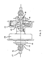
- FIG. 3 is an exploded view illustrating the rear hub assembly including one of the one-way clutches;
- FIG. 4 shows in views (A) and (B), side, cut-away views of the dual, pawl and ratchet mechanisms of the one-way clutches provided in accordance with an embodiment of the invention, in the forward and backup modes respectively;
- FIG. 5 is a front view of the rear hub assembly, broken away to illustrate components thereof in section;
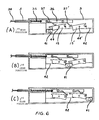
- FIG. 6 is a schematic view of the speed change device with the side thereof cut away so as to diagrammatically illustrate the operation of the mechanism in first, second, and third gear positions in views (A), (B), and (C), respectively.
- Referring to FIGS. 1 and 2, there is shown a bicycle having a frame 11 with a hub having a
main shaft 45 and a rear portion for receiving adrive hub assembly 14. The propulsion system utilizes a pivoted lever pedal system having the pedals 1, pedal levers 2 andspeed change devices 3, which are pivotally mounted on themain shaft 45 on the same side of the shaft. The speed or gearratio change devices 3 are mounted on the pedal levers 2, thereby enabling the mechanisms to be configured in a small space suitable for use on a BMX bicycle as shown in FIG. 1. The propulsion, lever mechanisms are one piece integrated propulsion lever and speed change device assemblies. The number of parts in these assemblies is less than in conventional bicycles, and their structure is simple and economical. Another advantage over conventional bicycles is that length of thedrive chain 9 is not changed when shifting gears. Thespeed change device 3 is designed so that the length of thechain 9 remains constant for all gear ratios. No derailleur system is necessary. There are no side thrusts on the chain. - The
speed change device 3, which may be also referred to as the lever arm length or gear ratio change device, has a housing in which alink member 41 is longitudinally moveable. The location of themember 41 is varied by means of rockingpawls 15, 15'. (FIG. 6.); the pivotal location of which is determined by camming them with aspeed change bar 36 from whichspring fingers 37 depend. Thebar 36 is biased by aspring 35 towards one end of the housing and is actuated to select the different locations and the different (three different) gear ratios by means ofcables 5 interconnected at a block 4 and connected through anextension cable 34 to a speed change control lever 6 (See FIG. 2) mounted on the frame 11. - The rear hub assembly has
sprockets 10 on opposite sides thereof and includes ahub 28 to which the rear wheels are attached in the usual way by spokes (not shown). Thehub 28 contains two, one-way clutches in each of the end drums thereof. These clutches enable propulsion power to be transferred to the rear wheel for driving the bicycle forwardly. The clutches also permit the bicycle to be rolled back without interference or the rear wheel locking up. - The rear wheel assemblies are connected to the pedal levers 2 by a loop made up of a flexible interconnecting chain and pulley system having a
flexible cable 9 and threeidler pulleys 7, 12 and 12a (see FIG. 2). The loop extends from thelink 13 which is connected to the movinglink member 41 in the speed change device through a portion of thecable 9, which is entrained around one of theidler pulleys 12, and then passes around one of thesprockets 10. The end of this chain portion is connected with a connector 11 to a cable 8 which passes around the idler pulley 7. It will be noted that the axis of thepulleys 12 and 12a, which can be sprockets, since the chain rollers are therein engaged, is essentially parallel to the axis of themain shaft 45. The axis of the idler pulley 7 is essentially perpendicular to the axis of the rear wheel axle 27 (the axis of the hub 28). From the end of the cable 8, another length of the flexible chain extends around theother sprocket 10, around the other idler roller 12a, and back down to another connectinglink 13 to themovable member 41 of the otherspeed change device 3. - The
cable 9 is a flexible cable made up of an elastomeric (rubber) belt which may be reinforced with thin steel wire and which has rollers (cylinders molded integrally with the belt), preferably of hard plastic such as nylon or polyurethane molded therein. Thischain 9 may be referred to as a robotic belt, and provides a precision timing chain which is sufficiently flexible so as to absorb any shocks and vibrations in the propulsion system. - It will therefore be seen that, when the bicycle rider executes a walking like motion, downward force is applied to the pedals 1 and through the levers 2 to the
speed changing devices 3. The rockingpawls 15 and 15' will be actuated to locate the connectinglinks 13 and themoveable members 41 at any of three gear positions selected by the control orshifter lever 6. Thislever 6 is a single lever, which is manually operable with one-hand. The forces are then transferred through thelink 13 and therobotic belt 9 to thesprockets 10 and thence to therear hub assembly 14. The bicycle is then propelled forwardly. As each pedal moves alternately up and down (see-saw motion), thechain 9 changes direction as it moves around the pulley 7. - The speed change devices will be best understood from FIG. 6. The housing of each device is a rectangular box having a slot defined by an
interior surface 42. The connectingmember 41 moves longitudinally in this slot (See also FIG. 2). The rockingpawls 15 and 15' are pivoted intermediate the ends thereof and approximately at their centers. Each pawl has step-shaped portions at the opposite ends thereof. In the first gear position, the connectinglink member 41 is located to the left as shown in FIG. 6A. This is because thebar 36 and thecamming fingers 37 and 37' pivot the pawls in the same direction, because they are located to the left (as viewed in FIG. 6) of thepivots 44 and 44' which connect the pawls to the housing. For the intermediate or second gear position (See FIG. 6B), the cable allows thespring 35 which biases the bar towards the right, to move thebar 36 to an intermediate position. There thefinger 37 is located so as to be slightly to the right of the pivot of one of thepawls 15, and to the left of the pivot in the other pawl 15'. The pawls then define an intermediate location in which the connectingmember 41 can be captured. The lever arm of the pedal lever (from the location of the connectingmember 41 to the main shaft 45), in the second gear position location, is longer than in the first gear position. This provides the second highest mechanical advantage of the three gear ratios available. In the third gear position, both of the rocking pawls are engaged to the right of their pivots and the location of the connectingmember 41 is all the way to the right in the housing. It will be observed that the upper surfaces of the rocking pawls are inclined to allow the pawls to rock against the bias of thefingers 37 and permit the movement of the connectinglink member 41 to the various gear positions. Such movement is permitted until the link is caught and captured by a step at the end of a link, as will be apparent from FIG. 6A, B, and C. - After a gear position is selected, force is transferred (see FIG. 2) from the
speed change device 3 through the connectinglink 13. The connecting link extends upward and is joined to therobotic belt 9. The belt moves over theidler pulley 12, which is attached to the frame. The belt then extends rearwardly and wraps around one of therear sprockets 10. After exiting the rear sprocket, the belt extends forwardly where it connects to the cable 8. The cable extends around the idler pulley 7. This pulley 7 provides a means of direction reversal for the cable. As the cable exits the opposite side of the idler pulley 7, it extends rearwardly, next to another portion of therobotic belt 9 that wraps around thesprocket 10 on the opposite side of thehub 14. Then the belt extends to the other idler pulley 12a and joins to another connectinglink 13 to thespeed change device 3 on the other pedal lever 2. It will therefore be seen that there is a continuous loop between the pedal levers which is provided by the flexible chain and pulley system. - The robotic belt system provides inertia shock relief, similar to when a persons' leg strikes the ground when walking. The
robotic belt 9 acts as shock absorber, as the pedals stop at the upper and lower limits of the stroke. Therefore, excess shock is not allowed to be transmitted to thespeed change devices 3 and to therear hub assembly 14. The result is a decrease in failure rate and an increase in the reliability of the propulsion system. All of the oscillating, up and down motion of the pedal levers is used for propulsion of the bicycle and leg motion is not wasted. A bicycle provided in accordance with the invention will be more comfortable and easier to ride for a longer period than is the case with a conventional bicycle. - It will further be observed that the stroke angle can be modified by changing the orientation of the housing of the speed change devices. The rider also can adjust the length of the stroke within the total operational arc. This enables all of the up and down motion of the pedal levers to be transferred to the rear wheel with a minimum loss of efficiency. Riders can learn to ride the bicycle without special skills, since the up and down motion of the pedal levers is the same as walking motion. As noted previously the inertia in the system, upon stopping the pedal levers at their upper and lower stroke limits, is shock absorbed by the flexible, robotic belt and the natural motion of the riders' legs. The result is minimum transfer of excess shock to the propulsion mechanisms.
- Gear selection may be made while the levers are stationary or while pedaling. However, certain conditions must exist for each of these cases. In a first case (Case I), shifting can take place while levers are stationary. When a lever 2 is positioned lower than horizontal as in FIG. 1 and an alternate gear is selected, gear changing may take place due to gravity on the moving
link member 41 and connectinglink 13. This gear repositioning will depend on the relative location of components, friction, and forces. Position movement could be from any of the gear positions to the other, as for example: first to second; second to third; or first to third. With the lever 2 positioned below horizontal, the opposite lever will be positioned above horizontal. Gravity shifting will not take place in the lever which is positioned above horizontal. When the levers are operated, the movinglink members 41 will then position correctly for the gear selected. - In the second case, shifting while pedaling, as the pedals and levers are operated and an alternate gear is selected, moving
link member 41 slides along thesurface 42 in the slot in the housing, and is captured at the gear position selected. This occurs when the angle between the connectinglink 13 and gear ratio selection link 3 permits this sliding motion. One full cycle of pedaling is required for both left and right moving links to reposition at the selected gear location. Gear selection can be made sequentially or non-sequentially as: 1-2-3, 3-2-1, or 1-3, 3-1, respectively. - Individual gear selection is accomplished as follows:
- a. First gear, Fig. 6 A, provides the highest mechanical advantage of the lever system.
Gear ratio selector 6 is positioned so that the maximum amount ofcable 34 is wrapped around its outer diameter. The cable slides withincable casing 5 and through the cable casing attaching point opening, at one end of gearratio selection bar 3. Thecable 34 then passes throughreturn spring 35 and terminates at theselection bar 36. With the maximum amount of cable pulled out of the housing of thedevice 3,spring 35 is in its most compressed condition. This spring andcable 34 combination positively locates theselection bar 36 at the selected gear ration position (first gear in this case). Gear ratio changes are accomplished by the single hand operated lever of theselector 6, either sequentially or non-sequentially. Shifting changes can be made while in motion, with any amount of force applied to the pedals, or at rest.Camming spring fingers 37 and 37', which are attached to theselection bar 36, forces the first gear portion of rockingpawl 15, which pivots onpin 44, in a position that will capture movinglink member 41 between itself and the wall of the gearratio selection bar 3. At this time spring 37' positions the second gear portion of rocking pawl 15' so that a stop location is provided for the moving link at second gear. This process is also duplicated in the opposingspeed change device 3, as its pedal and lever is operated. - b. Second gear, FIG. 6 (B), provides the second highest mechanical advantage of the three gear ratios available. The
gear ratio selector 6 is positioned such that a lesser amount ofcable 34 is wrapped around its outer diameter than first gear. The biasingspring 35 forces theselection bar 36 away from first gear position and into second gear position. Thecamming spring finger 37 is now in a position to pivot the second gear portion of rockingpawl 15 so a stop wall is provided. The spring finger 37' moves from first gear position on the pawl 15', toward the pivot pin 44'. The pawl 15' does not pivot and remains as located under first gear conditions. A positive stop location is provided for the movinglink member 41 at second gear position. When the pedals and levers are operated at such an angle that the movinglink member 41 slides onsurface 42, themember 41 moves toward second gear position. The second gear position of the rockingpawl 15 is in the path of the movinglink member 41. As the movinglink member 41 passes over the rockingpawl 15 the pawl pivots onpin 44 and allows the moving link to pass freely. When the link clears thatpawl 15 and stops at second gear position, thespring finger 37 pivots thepawl 15 back into a position that captures the movinglink member 41. Thecamming spring fingers 37 and 37' maintain thepawls 15 and 15', respectively, in positions that will not permit further sliding movement of the movinglink member 41 along theslot surface 42. This process is also duplicated in the opposing gearratio selection bar 3, as its pedal and lever is operated. - c. Third gear, FIG. 6 (C), provides the least mechanical advantage of the three gears available, but provides the greatest distance traveled for each stroke of the pedal levers 2. The
gear ratio selector 6 is positioned such that a minimum amount ofcable 34 is wrapped around its outer diameter. The biasingspring 35 forces theselection bar 36 away from second gear position. Thecamming spring finger 37 is repositioned but continues to position the rockingpawl 15 as it was in second gear position. This location of thepawl 15 also prevents movinglink member 41 from returning to first gear position. The camming spring finger 37' moves past the pivot pin 44' and forces the pawl 15' to pivot into third gear position. This provides a stop wall. The outer edge of the slot in the housing provides a second wall which captures the movinglink member 41 when it is located at third gear position. When the pawl 15' pivots from its second gear position, it moves out of the path of the movinglink member 41; therefore, only the stop wall at the end of the housing slot remains. As the pedal and lever is operated, the movinglink member 41 is prevented from moving into first gear position by the rockingpawl 15. The movinglink member 41 therefore slides alongsurface 42 toward third gear position. During the travel of thelink member 41, it encounters the angled surface of rocking pawl 15'. Thelink member 41 pushes against this angled surface and forces the pawl 15' away from thelink member 41. When the moving link stops against the end wall of the housing of thespeed change device 3, thespring 37 forces the rocking pawl 15' back into a position that provides a second stop wall for the movinglink member 41. Thelink member 41 is now captured in third gear position. This process is also duplicated in the opposingspeed change device 3, as its pedal and lever is operated. - The preceding exemplified sequential order shifting 1-2-3. Down shifting 3-2-1 or non-sequential shifting 1-3, 3-1 is also possible. To accomplish shifting other than in the exemplary sequence described above, the corresponding components interact to provide proper positioning for the moving
link member 41 in the gear selected. - Consider next the
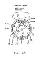
rear hub assembly 28 as shown particularly, in FIGS. 3-5. This assembly is characterized by dual, pawl-ratcheting mechanisms which provide the following functions: (1) forward motion to the bicycle when the left pedal lever is depressed; (2) forward motion when the right pedal lever is depressed; and (3) release of both the left and right drives to allow the bicycle to roll back. - The first of the pawl-ratcheting mechanisms is provided by a
ratchet wheel 25, which is free to rotate about therear wheel axle 27, andpawls 21 in adriver disk 20 which rotates with (is threaded on or keyed to) thesprocket 10. The second ratchet mechanism is provided by aclutch disk member 23 which is rotatable with the rear hub drum orshell 28 and aclutch pawl 26, which is pivotally mounted on the flange of theratchet wheel 25 by apivot pin 43. This second, pawl-ratcheting member includes aratchet wheel 22, which is also rotatable with thehub 28, and aback pawl 24 which is pivotally mounted on theclutch pawl 26. It will be observed that theclutch pawl 26 and backpawl 28 have the shape of the Greek letter Lambda. - There are
ball bearings 18,assembly cones 17 andnuts 16 which hold the clutch mechanism in the drums at the end of thehub 28. - In operation, when one pedal is depressed, the upper portion of the
robotic belt 9 is pulled forwardly over thesprocket 10. The rotating sprocket turns thesprocket hub 19 and thedriver disk 20 which are rotatable together as a unit. The rotatingdriver 20 allows one of the pawls 21 (all of which pawls 21 are biased outwardly from the center of the hub by springs 29) to engage one of the teeth of theratchet wheel 25. These teeth are on the inner periphery of theratchet wheel 25. It will be seen that these teeth are oppositely directed, in terms of pawl catching ability, to the teeth of theratchet 22 in the second, pawl-ratcheting mechanism. The forces applied to theratchet wheel 25 are transferred through thepivot pin 43, which is attached to the flange of that wheel and on which theclutch pawl 26 is pivotally mounted. Thepawl 26 is biased by ahairpin spring 30 mounted on the flange of theratchet wheel 25 on apin 31. The clutch pawl becomes locked into one of the notches on theclutch member 23. The clutch member is locked (e.g., keyed) to thehub 28. The hub will then turn and the spokes of the wheel will transfer the forces to the wheel rim, tire, and to the road surface for forward propulsion. - During the time that one of the pedals is depressed, the opposite pedal is moving upward. The closed loop robotic belt and pulley system will cause the non-driving
side hub sprocket 10 to turn in a free-turning, reverse direction. The lower portion of thebelt 9 is pulled forward and thesprocket 10 on the non-driving side rotates in the opposite direction of the driving sprocket. Thenon-driving sprocket hub 19 anddriver 20 are moved in a direction opposite to that of theratchet wheel 25. Thepawls 21 then disengage from the ratchet wheel teeth in the non-driving, one-way clutch mechanism. Thus the driver disk, hub and sprocket of the non-driving clutch mechanism turn freely when in non-driving condition. Thepawls 21 in each of the one-clutches engage and disengage alternately on each side of the rear hub assembly, as the pedals are operated up and down. - The second clutch mechanism enables the bicycle to be wheeled or rolled backwards for normal use. For a lever propelled bicycle to have this capability of roll back, without causing damage to the bicycle, is provided for by the second, pawl-ratcheting mechanism which releases or disengages the rear wheel from the
sprocket 10 and chain. The release mechanism enables the bicycle to be rolled backwards without interference with or damage to other parts of the transmission system. - The roll back mechanism functions during forward drive, as shown in FIG. 4(A), with the rear hub axle locked in position on the bicycle frame, and the
hub 28 rotating in a forward driving direction. Theback pawl 24, which is biased by thespring 32 and pivots on the backpawl pivot pin 33, disengages from theback ratchet 22 and follows the circumference thereof with a ratcheting action. The disengagement of the back ratchet and pawl enables theclutch pawl 26 to pivot onpin 43, and to engage theclutch member 23. This places the hub in the forward drive mode with the drive mechanism fully engaged. - For roll back, and as shown in FIG. 4(B), with the rear hub axle locked in position on the bicycle frame and hub rotating in the rearward direction, the
back pawl 24 engages theback ratchet 22. This actuates theclutch pawl 26 and disengages it from the clutch 23. Since the clutch is attached directly to thehub 28, the hub is disengaged from the forward drive mechanism and can rotate backwards freely and without damage to the transmission and to the mechanisms associated with the pedal levers. - It will be apparent that the direction of the ratchet teeth on the
ratchet wheel 25 is effectively opposite from the direction of the ratchet teeth on theratchet wheel 22, such that when theback pawl 24 is engaged, thepawls 21 on the driver disk are disengaged, and vice versa. - From the foregoing description it will be apparent that there has been provided an improved propulsion and speed change mechanism for lever propelled bicycles. It will be appreciated that the speed change mechanism and the one-way clutch mechanism which are provided in accordance with the invention may find independent use in lever propelled bicycles. Variations and modifications in the described mechanisms, within the scope of the invention, will undoubtedly suggest themselves to those skilled in the art. Accordingly the foregoing description should be taken as illustrative and not in a limiting sense.
- The invention may be summarized as follows:
- 1. A propulsion mechanism for a lever propelled bicycle having a frame with main and rear shaft receiving portions, pedal lever assemblies including speed change devices, said assemblies being pivotally mounted in said main shaft portion, a rear axle mounted in said rear shaft portion, a rear wheel hub journalled on said rear axle, a pair of sprockets also journalled on said rear axle, a pair of one-way clutches for connecting said sprockets to said hub, said propulsion mechanism being characterized in that:
a chain of flexible material is entrained in a loop extending between each of said lever assemblies' speed change devices and around said sprockets enabling the pedal levers to execute see-saw motion as said levers are oscillated upwardly and downwardly by force applied to the pedals thereof;
a pair of pawl and ratchet mechanisms is provided in each of said one-way clutches, one of which effects locking of the clutch to impart forward motion when said pedal levers are depressed downwardly and the other of which effects release of said clutch to enable said bicycle to be rolled backwards; and
each of said speed change devices having a housing having a surface extending away from said main shaft to define the length of the lever arm of said pedal lever assemblies to said main shaft, a plurality of pawls pivotally mounted in said housing to move transversely to said surface and define a plurality of locations each at a different lever arm length, a speed selection bar for pivoting said pawls, and a link connected to an end of the chain and moveable along said surface between different ones of said locations. - 2. The propulsion mechanism according to 1 wherein said chain comprises a flexible elongated belt having rollers spaced therealong, said rollers being engageable with said sprockets.
- 3. The propulsion mechanism according to 1 further comprising first, second, and third idler pulleys mounted on said frame, said loop extending from one of said speed change devices of one of said assemblies around a first of said idler pulleys, then around one said sprockets, then around the second of said idler pulleys, then around the other of said sprockets, and then around the third of said idler pulleys to the speed change device of the other of said assemblies.
- 4. The propulsion mechanism according to 3 wherein said first and third pulleys are coaxial with each other and have the axis thereof parallel to the axis of said main shaft, and said second pulley is mounted on said frame with its axis generally perpendicular to said rear axle axis.
- 5. The propulsion mechanism according to 4 wherein said loop includes connecting links between the ends of said chain and said speed change devices, and a cable around said second pulley connected to the ends of said chain portions opposite to said first named ends of said chain.
- 6. The propulsion mechanism according to 1 wherein said hub has drums each for receiving a different one of said one-way clutches in each of which:
the first of said pawl and ratchet mechanisms includes a ratchet wheel rotatable about said rear axle in its drum, a ratchet around the inner periphery of said wheel, a driver rotatable with one of said sprockets, at least one pawl pivotally mounted on said driver and biased towards said ratchet; and
the second of said pawl and ratchet mechanisms comprises a clutch member rotatable with said hub and having at least one notch therein, a first pawl pivotally mounted on said ratchet wheel of said first pawl and ratchet mechanism and engageable with said notch whereby forward driving force is transferred from said one sprocket through said driver and, said pawl of said first pawl and ratchet mechanism to said ratchet wheel and from said ratchet wheel to said first pawl, to said clutch member and to said hub. - 7. The propulsion mechanism according to 6 wherein said second pawl and ratchet mechanism further comprises a second ratchet wheel rotatable with said hub, a second pawl pivotally mounted on said first pawl and engageable with the ratchet of said second ratchet wheel for pivoting said first pawl and releasing said first pawl from said clutch member when said hub is rotated in the reverse direction.
- 8. The propulsion mechanism according to 7 wherein the ratchet on said first ratchet wheel and the ratchet on said second ratchet wheel are oriented with respect to each other such that the pawl engageable with said first ratchet wheel slips over the ratchet thereof when the pawl engageable with the ratchet of said second ratchet wheel is engaged, and vice versa.
- 9. The propulsion mechanism according to 7 wherein said first and second pawls of said second pawl and ratchet mechanisms when assembled are in the shape of the Greek letter Lambda.
- 10. The propulsion mechanism according to 1 wherein said speed change devices are mounted on arms of said assemblies on the same side of said shaft as said arms.
- 11. The propulsion mechanism according to 10 wherein said assemblies have pedal levers, said housings being mounted on said levers between the pedals of said assemblies and said main shaft.
- 12. The propulsion mechanism according to 1 wherein said surface in said housing and said housing define a longitudinal slot, a member moveable in said slot and linked to one end of said chain, said bar being moveable in said longitudinal direction, said pawls in said housing having pivots providing pivotal mountings for said pawls intermediate the ends thereof, means on said bar for engaging said pawls at different locations with respect to the pivots thereof for selectively pivoting said pawls in opposite directions to define different ones of said plurality of locations where said member which is linked to said chain is captured.
- 13. The propulsion mechanism according to 12 further comprising a speed change control, and means connecting said bar to said control.
- 14. The propulsion mechanism according to 13 further comprising means biasing said bar longitudinally toward one of the ends of said housing.
- 15. The propulsion mechanism according to 13 wherein said pawl engaging means are springs attached to said bar for camming said pawls to pivot them in said opposite directions.
- 16. The propulsion mechanism according to 15 wherein said pawls have steps in the opposite ends thereof.
- 17. The propulsion mechanism according to 15 wherein said springs are camming fingers spaced longitudinally along said bar, a different one of said fingers being provided for each of said pawls and being disposed in engagement therewith.
- 18. The propulsion mechanism according to 17 wherein the surfaces of said pawls facing said slot are inclined towards said slot from locations adjacent the pivot on which said pawls are pivoted to the opposite ends of said pawls.
- 19. A propulsion mechanism for a lever propelled bicycle having a frame with main and rear shaft receiving portions, pedal lever assemblies, said asemblies being pivotally mounted in said main shaft portion, a rear axle mounted in said rear shaft portion, a rear wheel hub journalled on said rear axle, a pair of sprockets also journalled on said rear axle, a pair of one-way clutches for connecting said sprockets to said hub, said propulsion mechanism being characterized in a pair of pawl and ratchet mechanisms is provided in each of said one-way clutches, one of which effects locking of the clutch to impart forward motion when said pedal levers are depressed downwardly and the other of which effects release of said clutch to enable said bicycle to be rolled backwards.
- 20. The propulsion mechanism according to 19 wherein said hub has drums each for receiving a different one of said one-way clutches in each of which:
the first of said pawl and ratchet mechanism includes a ratchet wheel rotatable about said rear axle in its drum, a ratchet around the inner periphery of said wheel, a driver rotatable with one of said sprockets, at least one pawl pivotally mounted on said driver and biased towards said ratchet; and
the second of said pawl and ratchet mechanisms comprises a clutch member rotatable with said hub and having at least one notch therein, a first pawl pivotally mounted on said ratchet wheel of said first pawl and ratchet mechanism and engageable with said notch whereby forward driving force is transferred from said one sprocket through said driver and said pawl of said first pawl and ratchet mechanism to said ratchet wheel and from said ratchet wheel to said first pawl, to said clutch member and to said hub. - 21. The propulsion mechanism according to 20 wherein said second pawl and ratchet mechanism further comprises a second ratchet wheel rotatable with said hub, a second pawl pivotally mounted on said first pawl and engageable with the ratchet of said second ratchet wheel for pivoting said first pawl and releasing said first pawl from said clutch member when said hub is rotated in the reverse direction.
- 22. The propulsion mechanism according to 20 wherein the ratchet on said first ratchet wheel and the ratchet on said second ratchet wheel are oriented with respect to each other such that the pawl engageable with said first ratchet wheel slips over the ratchet thereof when the pawl engageable with the ratchet of said second ratchet wheel is engaged, and vice versa.
- 23. The propulsion mechanism according to 20 wherein said first and second pawls of said second pawl and ratchet mechanisms when assembled are in the shape of the Greek letter Lambda.
- 24. In a propulsion mechanism for a lever propelled bicycle having a frame with main and rear shaft receiving portions and having pedal lever assemblies including lever arm length change devices, said assemblies being pivotally mounted in said main shaft portion, a rear axle mounted in said rear shaft portion, a rear wheel hub journalled on said rear axle, at least one sprocket also journalled on said rear axle, a chain around said sprocket for transferring propulsion forces from the devices to said rear wheel hub and enabling the pedal levers to execute see-saw motion as said levers are oscillated upwardly and downwardly by force applied to the pedals thereof the improvement wherein each of said change devices comprises a housing having a surface extending away from said main shaft to define the length of the lever arm of said pedal lever assemblies to said main shaft, a plurality of pawls pivotally mounted in said housing to move transversely to said surface and define a plurality of locations each at a different lever arm length, a speed change bar for pivoting said pawls, and a link connected to an end of the chain and moveable along said surface between different ones of said locations.
- 25. The propulsion mechanism according to 23 wherein said devices are mounted on arms of said assemblies on the same side of said shaft as said arms.
- 26. The propulsion mechanism according to 24 wherein said assemblies have pedal levers, said housings being mounted on said levers between the pedals of said assemblies and said main shaft.
- 27. The propulsion mechanism according to 23 wherein said surface in said housing and said housing define a longitudinal slot, a member moveable in said slot and linked to one end of said chain, said bar being moveable in said longitudinal direction, said pawls in said housing having pivots providing pivotal mountings for said pawls intermediate the ends thereof, means on said bar for engaging said pawls at different locations with respect to the pivots thereof for selectively pivoting said pawls in opposite directions to define different ones of said plurality of locations where said member which is linked to said chain is captured.
- 28. The propulsion mechanism according to 26 further comprising a speed change control and means connecting said bar to said control.
- 29. The propulsion mechanism according to 27 further comprising means biasing said bar longitudinally toward one of the ends of said housing.
- 30. The propulsion mechanism according to 27 wherein said pawl engaging means are springs attached to said bar for camming said pawls to pivot them in said opposite directions.
- 31. The propulsion mechanism according to 29 wherein said pawls have steps in the opposite ends thereof.
- 32. The propulsion mechanism according to 29 wherein said springs are camming fingers spaced longitudinally along said bar, a different one of said fingers being provided for each of said pawls and being disposed in engagement therewith.
- 33. The propulsion mechanism according to 31 wherein the surfaces of said pawls facing said slot are inclined towards said slot from locations adjacent the pivot on which pawls are pivoted to the opposite ends of said pawls.
Claims (20)
the first of said pawl and ratchet mechanism includes a ratchet wheel rotatable about said rear axle in its drum, a ratchet around the inner periphery of said wheel, a driver rotatable with one of said sprockets, at least one pawl pivotally mounted on said driver and biased towards said ratchet; and
the second of said pawl and ratchet mechanisms comprises a clutch member rotatable with said hub and having at least one notch therein, a first pawl pivotally mounted on said ratchet wheel of said first pawl and ratchet mechanism and engageable with said notch whereby forward driving force is transferred from said one sprocket through said driver and said pawl of said first pawl and ratchet mechanism to said ratchet wheel and from said ratchet wheel to said first pawl, to said clutch member and to said hub.
Applications Claiming Priority (2)
| Application Number | Priority Date | Filing Date | Title |
|---|---|---|---|
| US759995 | 1985-07-29 | ||
| US06/759,995 US4630839A (en) | 1985-07-29 | 1985-07-29 | Propulsion mechanism for lever propelled bicycles |
Publications (2)
| Publication Number | Publication Date |
|---|---|
| EP0210336A2 true EP0210336A2 (en) | 1987-02-04 |
| EP0210336A3 EP0210336A3 (en) | 1987-09-30 |
Family
ID=25057726
Family Applications (1)
| Application Number | Title | Priority Date | Filing Date |
|---|---|---|---|
| EP86104852A Withdrawn EP0210336A3 (en) | 1985-07-29 | 1986-04-09 | Propulsion mechanism for lever propelled bicycles |
Country Status (9)
| Country | Link |
|---|---|
| US (1) | US4630839A (en) |
| EP (1) | EP0210336A3 (en) |
| JP (1) | JPS6229483A (en) |
| KR (1) | KR890004250B1 (en) |
| CN (2) | CN85107618A (en) |
| AU (2) | AU577702B2 (en) |
| BR (1) | BR8601945A (en) |
| IL (1) | IL79232A0 (en) |
| NZ (1) | NZ216391A (en) |
Cited By (3)
| Publication number | Priority date | Publication date | Assignee | Title |
|---|---|---|---|---|
| GB2241476A (en) * | 1990-03-03 | 1991-09-04 | Show Lang Huang | Step-drive bicycle |
| WO1995025035A1 (en) | 1994-03-17 | 1995-09-21 | LANTOS, Mihály | Alternating drive for wheeled vehicles |
| WO2020225581A1 (en) * | 2019-05-06 | 2020-11-12 | Kohlheb Robert | Wheel hub arrangement for drives with rotated drum |
Families Citing this family (98)
| Publication number | Priority date | Publication date | Assignee | Title |
|---|---|---|---|---|
| US4630839A (en) * | 1985-07-29 | 1986-12-23 | Alenax Corp. | Propulsion mechanism for lever propelled bicycles |
| JPS62110003U (en) * | 1985-12-27 | 1987-07-14 | ||
| US4953882A (en) * | 1989-03-29 | 1990-09-04 | Craig Jr Chester L | Transmission apparatus for bicycle or like pedal-operated vehicle |
| US5163886A (en) * | 1990-08-01 | 1992-11-17 | Augustine Rheem | Exercising and rehabilitation apparatus |
| US5335927A (en) * | 1993-05-10 | 1994-08-09 | Islas John J | Pedaled propulsion system |
| DE4329814A1 (en) * | 1993-09-03 | 1995-03-09 | Thomas Sittler | Bicycle with pedal drive |
| US5618240A (en) * | 1995-06-07 | 1997-04-08 | Gilbert; Raymond D. | Sprocket ratio changer |
| US5785337A (en) * | 1996-07-15 | 1998-07-28 | Ming; Kuan Shang | Propulsion system for a bicycle |
| US6199884B1 (en) | 1996-12-23 | 2001-03-13 | 7444353 Alberta Ltd. | Helical drive bicycle |
| US6241565B1 (en) | 1996-12-23 | 2001-06-05 | Helixsphere Technologies, Inc. | Helical drive human powered boat |
| IL133376A0 (en) * | 1997-06-09 | 2001-04-30 | World Ind Co Ltd | Apparatus for changing rotation of pedal shaft for bicycle |
| US6551210B2 (en) * | 2000-10-24 | 2003-04-22 | Motion Technologies, Llc. | Continuously variable transmission |
| US6298740B1 (en) | 1999-03-19 | 2001-10-09 | Justin C. Bridges | Adjustable rotational transmission assembly |
| US6382043B1 (en) * | 2000-08-04 | 2002-05-07 | Lin Ruey-Chieh | Transmission assembly for a bicycle having forward/back gear |
| EP1350042A2 (en) | 2000-10-10 | 2003-10-08 | Laird B. Gogins | Mechanical transmission |
| RU2289045C2 (en) | 2001-04-26 | 2006-12-10 | МОУШН ТЕКНОЛОДЖИЗ, ЛЛСи | Infinitely variable gear box |
| US20030173755A1 (en) * | 2002-03-18 | 2003-09-18 | John Lachenmayer | Bicycle drive mechanism |
| KR200307145Y1 (en) * | 2002-12-03 | 2003-03-15 | 박훈근 | A bicycle worked by handle operating |
| US7011600B2 (en) | 2003-02-28 | 2006-03-14 | Fallbrook Technologies Inc. | Continuously variable transmission |
| US7037242B2 (en) * | 2003-07-03 | 2006-05-02 | Octane Fitness, Llc | Angle adjustable pedals for elliptical exercisers |
| US7166052B2 (en) | 2003-08-11 | 2007-01-23 | Fallbrook Technologies Inc. | Continuously variable planetary gear set |
| US7214159B2 (en) | 2003-08-11 | 2007-05-08 | Fallbrook Technologies Inc. | Continuously variable planetary gear set |
| US7011376B2 (en) * | 2003-08-25 | 2006-03-14 | Sepulveda Richard J | Systems and methods for propelling a vehicle |
| US7487987B2 (en) | 2004-01-05 | 2009-02-10 | Ningbo Landsurf Sports Equipment Co. Ltd. | User-propelled riding toys with simultaneous pedal recovery system |
| DK1774199T3 (en) | 2004-07-21 | 2013-09-16 | Fallbrook Ip Co Llc | Rolling traction planetary drive |
| US20060046884A1 (en) * | 2004-09-01 | 2006-03-02 | Alan Estergomy | Drive train |
| US20060055144A1 (en) * | 2004-09-13 | 2006-03-16 | Stephen Norman | Muscle-powered continuously variable drive system and apparatus having same |
| JP4974896B2 (en) | 2004-10-05 | 2012-07-11 | フォールブルック テクノロジーズ インコーポレイテッド | Continuously variable transmission |
| AU2006299847A1 (en) | 2005-08-22 | 2007-04-19 | Viryd Technologies Inc. | Fluid energy converter |
| US7670243B2 (en) | 2005-08-24 | 2010-03-02 | Fallbrook Technologies, Inc. | Continuously variable transmission |
| EP1945490B1 (en) | 2005-10-28 | 2018-12-05 | Fallbrook Intellectual Property Company LLC | Electromotive drives |
| EP1954959B1 (en) | 2005-11-22 | 2013-05-15 | Fallbrook Intellectual Property Company LLC | Continuously variable transmission |
| CA2930483C (en) | 2005-12-09 | 2017-11-07 | Fallbrook Intellectual Property Company Llc | Continuously variable transmission |
| EP1811202A1 (en) | 2005-12-30 | 2007-07-25 | Fallbrook Technologies, Inc. | A continuously variable gear transmission |
| US7882762B2 (en) | 2006-01-30 | 2011-02-08 | Fallbrook Technologies Inc. | System for manipulating a continuously variable transmission |
| WO2007106874A2 (en) | 2006-03-14 | 2007-09-20 | Autocraft Industries, Inc. | Improved wheelchair |
| KR100754941B1 (en) * | 2006-04-21 | 2007-09-03 | (주)코페스 | Mutipurpose power generating apparatus |
| WO2007123319A1 (en) * | 2006-04-21 | 2007-11-01 | Cofes Co., Ltd. | Mutipurpose power generating apparatus |
| CN101484350A (en) | 2006-05-11 | 2009-07-15 | 瀑溪技术公司 | Continuously variable drivetrain |
| US7293789B1 (en) * | 2006-06-15 | 2007-11-13 | Boris Efros | Wide power range bicycle with positive intuitive gear shifting system |
| CN102269056B (en) | 2006-06-26 | 2013-10-23 | 福博科技术公司 | Continuously variable transmission |
| US20080106061A1 (en) * | 2006-10-18 | 2008-05-08 | Ohannes Meguerditchian | Drive apparatus |
| US20080096708A1 (en) * | 2006-10-18 | 2008-04-24 | Ohannes Meguerditchian | Drive apparatus |
| WO2008057507A1 (en) | 2006-11-08 | 2008-05-15 | Fallbrook Technologies Inc. | Clamping force generator |
| US7717448B2 (en) * | 2007-01-10 | 2010-05-18 | Brian Roger Clemons | Ratchet-action drive mechanism for human power |
| US8738255B2 (en) | 2007-02-01 | 2014-05-27 | Fallbrook Intellectual Property Company Llc | Systems and methods for control of transmission and/or prime mover |
| CN104121345B (en) | 2007-02-12 | 2017-01-11 | 福博科知识产权有限责任公司 | Continuously variable transmission and method therefor |
| CN103438207B (en) | 2007-02-16 | 2016-08-31 | 福博科技术公司 | Unlimited speed changing type buncher, buncher and method, assembly, sub-component and parts |
| CN105626801B (en) | 2007-04-24 | 2019-05-28 | 福博科知识产权有限责任公司 | Electric traction drives |
| US8641577B2 (en) | 2007-06-11 | 2014-02-04 | Fallbrook Intellectual Property Company Llc | Continuously variable transmission |
| CN101074705B (en) * | 2007-06-28 | 2010-07-07 | 力帆实业(集团)股份有限公司 | Clutch-separating cable |
| CA2692476C (en) | 2007-07-05 | 2017-11-21 | Fallbrook Technologies Inc. | Continuously variable transmission |
| US8996263B2 (en) | 2007-11-16 | 2015-03-31 | Fallbrook Intellectual Property Company Llc | Controller for variable transmission |
| WO2009085773A1 (en) | 2007-12-21 | 2009-07-09 | Fallbrook Technologies Inc. | Automatic transmissions and methods therefor |
| US8313405B2 (en) | 2008-02-29 | 2012-11-20 | Fallbrook Intellectual Property Company Llc | Continuously and/or infinitely variable transmissions and methods therefor |
| JP4891943B2 (en) * | 2008-05-02 | 2012-03-07 | 喬紳股▲ふん▼有限公司 | Hub claw wheel structure |
| US8317651B2 (en) | 2008-05-07 | 2012-11-27 | Fallbrook Intellectual Property Company Llc | Assemblies and methods for clamping force generation |
| US8535199B2 (en) | 2008-06-06 | 2013-09-17 | Fallbrook Intellectual Property Company Llc | Infinitely variable transmissions, continuously variable transmissions, methods, assemblies, subassemblies, and components therefor |
| EP2304272B1 (en) | 2008-06-23 | 2017-03-08 | Fallbrook Intellectual Property Company LLC | Continuously variable transmission |
| WO2010017242A1 (en) | 2008-08-05 | 2010-02-11 | Fallbrook Technologies Inc. | Methods for control of transmission and prime mover |
| US7946194B2 (en) * | 2008-08-08 | 2011-05-24 | Michael Owen Davis | Continuously variable compound lever human powered transmission |
| US8469856B2 (en) | 2008-08-26 | 2013-06-25 | Fallbrook Intellectual Property Company Llc | Continuously variable transmission |
| US8167759B2 (en) | 2008-10-14 | 2012-05-01 | Fallbrook Technologies Inc. | Continuously variable transmission |
| CN101525031B (en) * | 2009-04-10 | 2011-05-18 | 重庆隆鑫机车有限公司 | Back brake pedal of two-wheeled vehicle |
| CA2756273C (en) | 2009-04-16 | 2017-06-27 | Fallbrook Technologies Inc. | Stator assembly and shifting mechanism for a continuously variable transmission |
| JP5408481B2 (en) * | 2009-06-12 | 2014-02-05 | 隆司 島宗 | Human drive mechanism |
| JP5188474B2 (en) * | 2009-08-19 | 2013-04-24 | 喬紳股▲ふん▼有限公司 | Normally closed silent hub ratchet structure |
| US9114848B2 (en) * | 2009-09-04 | 2015-08-25 | Zike, Llc | Pedal-drive system for manually propelling multi-wheeled cycles |
| KR101135398B1 (en) * | 2009-12-28 | 2012-04-20 | 이용식 | a multipurpose bicycle |
| US8512195B2 (en) | 2010-03-03 | 2013-08-20 | Fallbrook Intellectual Property Company Llc | Infinitely variable transmissions, continuously variable transmissions, methods, assemblies, subassemblies, and components therefor |
| US8888643B2 (en) | 2010-11-10 | 2014-11-18 | Fallbrook Intellectual Property Company Llc | Continuously variable transmission |
| WO2012138610A1 (en) | 2011-04-04 | 2012-10-11 | Fallbrook Intellectual Property Company Llc | Auxiliary power unit having a continuously variable transmission |
| US8840127B2 (en) | 2012-01-04 | 2014-09-23 | Robert Musgrove | Spiral cone pulley reciprocal pedal drive system and methods |
| WO2013112408A1 (en) | 2012-01-23 | 2013-08-01 | Fallbrook Intellectual Property Company Llc | Infinitely variable transmissions, continuously variable transmissions methods, assemblies, subassemblies, and components therefor |
| CA2909565A1 (en) | 2013-04-19 | 2014-10-23 | Fallbrook Intellectual Property Company Llc | Continuously variable transmission |
| TW201514057A (en) * | 2013-10-14 | 2015-04-16 | Chen zheng he | Two-wheel vehicle structure (2) |
| US10433612B2 (en) | 2014-03-10 | 2019-10-08 | Icon Health & Fitness, Inc. | Pressure sensor to quantify work |
| CZ2014267A3 (en) * | 2014-04-18 | 2015-11-25 | František Böhm | Environment -friendly vehicle for transportation of persons an/or luggage |
| US9783261B2 (en) * | 2014-09-21 | 2017-10-10 | Efim GIMPEL | Demountable device for transformation of treadle lever rocking movement into rotary movement of bicycle#S drive shaft |
| EA030170B1 (en) * | 2015-01-20 | 2018-06-29 | Геннадий Павлович Крикун | Bicycle |
| US10047861B2 (en) | 2016-01-15 | 2018-08-14 | Fallbrook Intellectual Property Company Llc | Systems and methods for controlling rollback in continuously variable transmissions |
| US10322767B2 (en) | 2016-01-24 | 2019-06-18 | Costel Dragomir | Carry-on foldable stepper scooter |
| CN109154368B (en) | 2016-03-18 | 2022-04-01 | 福博科知识产权有限责任公司 | Continuously variable transmission, system and method |
| US10023266B2 (en) | 2016-05-11 | 2018-07-17 | Fallbrook Intellectual Property Company Llc | Systems and methods for automatic configuration and automatic calibration of continuously variable transmissions and bicycles having continuously variable transmissions |
| ES2651195B2 (en) * | 2016-07-21 | 2018-05-16 | Universitat Politécnica de Catalunya | REMOVABLE KIT FOR ALTERNATIVE PEDALEO FOR STANDARD BOX BICYCLES |
| TWM537062U (en) * | 2016-08-09 | 2017-02-21 | Vivasports Co Ltd | Transmission device for fitness or bicycle |
| CN207089571U (en) * | 2017-06-05 | 2018-03-13 | 上海昶意机械制造有限公司 | A kind of scooter of two pedal driving |
| CN107284596B (en) * | 2017-08-03 | 2023-08-15 | 蒙山县生产力促进中心 | Alternate pedal type labor-saving bicycle transmission device |
| US11187285B2 (en) * | 2017-12-09 | 2021-11-30 | Icon Health & Fitness, Inc. | Systems and methods for selectively rotationally fixing a pedaled drivetrain |
| CN108502081A (en) * | 2018-05-25 | 2018-09-07 | 曾东斌 | A kind of adjustable labour-saving bicycle of speed |
| US11565767B2 (en) * | 2018-06-21 | 2023-01-31 | Rashad Na'im Scarborough | Compound torque multiplying lever propelled bicycle |
| CN108749989A (en) * | 2018-08-20 | 2018-11-06 | 许瑞雪 | A kind of rear-mounted bicycle with pedal |
| US11215268B2 (en) | 2018-11-06 | 2022-01-04 | Fallbrook Intellectual Property Company Llc | Continuously variable transmissions, synchronous shifting, twin countershafts and methods for control of same |
| US11174922B2 (en) | 2019-02-26 | 2021-11-16 | Fallbrook Intellectual Property Company Llc | Reversible variable drives and systems and methods for control in forward and reverse directions |
| US11286018B1 (en) | 2019-07-26 | 2022-03-29 | Cyclazoom, LLC | Linearly actuated vehicle providing increased force actuation |
| US11312448B1 (en) | 2019-07-26 | 2022-04-26 | Cyclazoom, LLC | Bicycle with force-increasing actuation system |
| US10858065B1 (en) * | 2019-07-26 | 2020-12-08 | Cyclazoom Llc | Linearly actuated vehicle |
| CN111038640A (en) * | 2020-01-15 | 2020-04-21 | 蔡楚盛 | Step-type weight-driven chainless lever labor-saving power device |
Citations (5)
| Publication number | Priority date | Publication date | Assignee | Title |
|---|---|---|---|---|
| FR4282E (en) * | 1902-07-07 | 1905-11-30 | Guillaume Gathier | Propulsion mechanism for cycles |
| GB667655A (en) * | 1949-04-21 | 1952-03-05 | Andre Louis Havet | Hub for bicycles controlled through reciprocating pedalling and allowing forward and rearward freewheeling |
| WO1983001764A1 (en) * | 1981-11-16 | 1983-05-26 | Boris Efros | Improved high speed cycle |
| EP0088448A2 (en) * | 1982-03-10 | 1983-09-14 | Yim, Byung D. | Propulsion and speed change mechanism for lever propelled bicycles |
| GB2127111A (en) * | 1982-07-09 | 1984-04-04 | Kimihiro Tsuchie | Cycle driving mechanism |
Family Cites Families (3)
| Publication number | Priority date | Publication date | Assignee | Title |
|---|---|---|---|---|
| US3759534A (en) * | 1970-10-24 | 1973-09-18 | Nippon Piston Ring Co Ltd | Apex seal for rotary piston engine |
| AU6052580A (en) * | 1979-05-04 | 1980-11-20 | Energenic Propulsions Ltd. | Efficient versatile oscillating pedal cycle |
| US4630839A (en) * | 1985-07-29 | 1986-12-23 | Alenax Corp. | Propulsion mechanism for lever propelled bicycles |
-
1985
- 1985-07-29 US US06/759,995 patent/US4630839A/en not_active Expired - Lifetime
- 1985-10-12 CN CN198585107618A patent/CN85107618A/en active Pending
- 1985-11-16 CN CN198585204908U patent/CN85204908U/en not_active Expired - Lifetime
- 1985-12-20 KR KR1019850009652A patent/KR890004250B1/en not_active IP Right Cessation
-
1986
- 1986-04-09 EP EP86104852A patent/EP0210336A3/en not_active Withdrawn
- 1986-04-30 BR BR8601945A patent/BR8601945A/en not_active IP Right Cessation
- 1986-06-03 NZ NZ216391A patent/NZ216391A/en unknown
- 1986-06-19 AU AU58941/86A patent/AU577702B2/en not_active Ceased
- 1986-06-25 IL IL79232A patent/IL79232A0/en unknown
- 1986-07-29 JP JP61178605A patent/JPS6229483A/en active Pending
-
1988
- 1988-08-03 AU AU20377/88A patent/AU2037788A/en not_active Abandoned
Patent Citations (5)
| Publication number | Priority date | Publication date | Assignee | Title |
|---|---|---|---|---|
| FR4282E (en) * | 1902-07-07 | 1905-11-30 | Guillaume Gathier | Propulsion mechanism for cycles |
| GB667655A (en) * | 1949-04-21 | 1952-03-05 | Andre Louis Havet | Hub for bicycles controlled through reciprocating pedalling and allowing forward and rearward freewheeling |
| WO1983001764A1 (en) * | 1981-11-16 | 1983-05-26 | Boris Efros | Improved high speed cycle |
| EP0088448A2 (en) * | 1982-03-10 | 1983-09-14 | Yim, Byung D. | Propulsion and speed change mechanism for lever propelled bicycles |
| GB2127111A (en) * | 1982-07-09 | 1984-04-04 | Kimihiro Tsuchie | Cycle driving mechanism |
Cited By (5)
| Publication number | Priority date | Publication date | Assignee | Title |
|---|---|---|---|---|
| GB2241476A (en) * | 1990-03-03 | 1991-09-04 | Show Lang Huang | Step-drive bicycle |
| WO1995025035A1 (en) | 1994-03-17 | 1995-09-21 | LANTOS, Mihály | Alternating drive for wheeled vehicles |
| CN1061614C (en) * | 1994-03-17 | 2001-02-07 | 加伯尔·拉茨 | Alternating drive for vehicles |
| WO2020225581A1 (en) * | 2019-05-06 | 2020-11-12 | Kohlheb Robert | Wheel hub arrangement for drives with rotated drum |
| US11485175B2 (en) | 2019-05-06 | 2022-11-01 | Róbert KOHLHÉB | Wheel hub arrangement for drives with rotated drum |
Also Published As
| Publication number | Publication date |
|---|---|
| AU5894186A (en) | 1987-02-05 |
| EP0210336A3 (en) | 1987-09-30 |
| AU577702B2 (en) | 1988-09-29 |
| CN85204908U (en) | 1986-08-13 |
| US4630839A (en) | 1986-12-23 |
| AU2037788A (en) | 1988-11-03 |
| JPS6229483A (en) | 1987-02-07 |
| IL79232A0 (en) | 1986-09-30 |
| BR8601945A (en) | 1987-03-10 |
| NZ216391A (en) | 1989-04-26 |
| KR890004250B1 (en) | 1989-10-28 |
| CN85107618A (en) | 1987-01-28 |
| KR870001083A (en) | 1987-03-11 |
Similar Documents
| Publication | Publication Date | Title |
|---|---|---|
| US4630839A (en) | Propulsion mechanism for lever propelled bicycles | |
| US4030373A (en) | Variable speed drive for a bicycle | |
| US6431573B1 (en) | Automatic transmission for a cycle, such as a bicycle, and a cycle having such as transmission | |
| US3984129A (en) | Reciprocating pedal drive mechanism for a vehicle | |
| US4574649A (en) | Propulsion and speed change mechanism for lever propelled bicycles | |
| US3954282A (en) | Variable speed reciprocating lever drive mechanism | |
| US7004487B2 (en) | Continuously variable transmission for bicycles | |
| TWI247712B (en) | Bicycle transmission | |
| EP2193068B1 (en) | Drive mechanism for a vehicle propellable by muscle power and vehicle | |
| US4300784A (en) | Efficient, versatile oscillating pedal cycle | |
| US6157149A (en) | Kinetic energy regenerating device for an electric motor bicycle | |
| EP0803430B1 (en) | Hub transmission for bicycle | |
| US4353569A (en) | Freewheel flywheel transmission system | |
| EP0803431B1 (en) | Hub transmission for bicycle | |
| US6129646A (en) | Apparatus for propelling a cycle | |
| US20040067804A1 (en) | Bicycle drive train | |
| US4782722A (en) | Bicycle drive system | |
| US20040066017A1 (en) | Bicycle drive train | |
| US6382043B1 (en) | Transmission assembly for a bicycle having forward/back gear | |
| US6916031B1 (en) | Frictionless bicycle stopping device | |
| RU2059507C1 (en) | Bicycle "annushka" | |
| KR20030067016A (en) | Device for driving forward bicycle | |
| KR200255796Y1 (en) | Power driving device of bicycle | |
| EP2679480B1 (en) | Vehicle | |
| CN1005554B (en) | The transmission of lever cable wire can be stablized the bicycle stopping |
Legal Events
| Date | Code | Title | Description |
|---|---|---|---|
| PUAI | Public reference made under article 153(3) epc to a published international application that has entered the european phase |
Free format text: ORIGINAL CODE: 0009012 |
|
| 17P | Request for examination filed |
Effective date: 19860521 |
|
| AK | Designated contracting states |
Kind code of ref document: A2 Designated state(s): AT BE CH DE FR GB IT LI LU NL SE |
|
| PUAL | Search report despatched |
Free format text: ORIGINAL CODE: 0009013 |
|
| AK | Designated contracting states |
Kind code of ref document: A3 Designated state(s): AT BE CH DE FR GB IT LI LU NL SE |
|
| 17Q | First examination report despatched |
Effective date: 19890206 |
|
| RAP3 | Party data changed (applicant data changed or rights of an application transferred) |
Owner name: ALENAX CORPORATION |
|
| STAA | Information on the status of an ep patent application or granted ep patent |
Free format text: STATUS: THE APPLICATION IS DEEMED TO BE WITHDRAWN |
|
| 18D | Application deemed to be withdrawn |
Effective date: 19910527 |
|
| RIN1 | Information on inventor provided before grant (corrected) |
Inventor name: SEOL, MARN TAEK |