EP0211562A2 - Knife sheet-folder - Google Patents
Knife sheet-folder Download PDFInfo
- Publication number
- EP0211562A2 EP0211562A2 EP86305644A EP86305644A EP0211562A2 EP 0211562 A2 EP0211562 A2 EP 0211562A2 EP 86305644 A EP86305644 A EP 86305644A EP 86305644 A EP86305644 A EP 86305644A EP 0211562 A2 EP0211562 A2 EP 0211562A2
- Authority
- EP
- European Patent Office
- Prior art keywords
- nip
- sheet
- folding
- cylinders
- blade
- Prior art date
- Legal status (The legal status is an assumption and is not a legal conclusion. Google has not performed a legal analysis and makes no representation as to the accuracy of the status listed.)
- Granted
Links
Images

Classifications
-
- B—PERFORMING OPERATIONS; TRANSPORTING
- B65—CONVEYING; PACKING; STORING; HANDLING THIN OR FILAMENTARY MATERIAL
- B65H—HANDLING THIN OR FILAMENTARY MATERIAL, e.g. SHEETS, WEBS, CABLES
- B65H45/00—Folding thin material
- B65H45/12—Folding articles or webs with application of pressure to define or form crease lines
- B65H45/18—Oscillating or reciprocating blade folders
Definitions
- This invention relates generally to a knife folder particularly, but not exclusively, for use with an electrophotographic printing machine for folding sheets exiting the machine.
- US-A-1 124 375 discloses a folding and stapling device in which a folder blade drives and creases collected sheets into a receiving head and clips of an arm member.
- US-A-4 508 527 discloses a method and apparatus for quantitatively dividing zig-zag folded sheets.
- a sheet of paper having a plurality of linear perforations is continuously transferred vertically through a roller and is folded in zig-zag form by operation of a crank mechanism.
- an improved knife folder in which a blade collapses a sheet into position to be gently buckled by nip rollers into a nip formed by a pair of folding cylinders that apply a final fold to the sheet and thereby insuring positive acquisition of the sheet, elimination of a critical set up and the potential for knife related copy damage while reducing potential for disturbing the centering of the sheet over the folding cylinders.
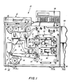
- printing machine 10 includes conventional controller 58 and a recirculating document handling system 12 for advancing successive original documents onto the platen of the precessing module 14.
- controller 58 controls the various processing stations employed in processing module 14 to advance successive original documents onto the platen of the precessing module 14.
- Processing module 14 employs a belt 16 having a photoconductive surface deposed on a conductive substrate.
- the photoconductive surface is made from a selenium alloy with the conductive substrate being preferably made from an aluminum alloy which is electrically grounded.
- Belt 16 advances successive portions of the p hotoconductive surface sequentially through the various processing stations disposed about the path of movement thereof.
- Belt 16 is entrained about stripping roller 18, tensioning roller 20 and drive roller 22.
- Drive roller 22 is coupled to a suitable motor so as to rotate and advance belt 16.
- a corona generating device 24 charges the photoconductive surface of belt 16 to a relatively high, substantially uniform potential.
- the charged portion thereof is advanced through exposure station B.
- an original document is advanced by the recirculating document handling system 12 to a transparent platen 26.
- Lamps 28 flash light rays onto the original document.
- the light rays reflected from the original document are transmitted through lens 30 forming a light image thereof.
- Lens 30 focuses the light image onto the charged portion of the photoconductive surface to selectively dissipate the charge thereon. This records an electrostatic image on the photoconductive surface of belt 16 which corresponds to the informational areas contained within the original document.
- belt 16 advances the electrostatic latent image recorded on the photoconductive surface to development station C.
- a magnetic brush development system indicated generally by the reference numeral 32, advances developer material into contact with the latent image.
- magnetic brush development system 32 includes two magnetic brush developer rollers 34 and 36. Each roller advances developer material into contact with the latent image. These rollers form a brush of carrier granules and toner particles extending outwardly therefrom. The latent image attracts the toner particles from the carrier granules forming a toner powder image on the photoconductive surface of belt 16.
- belt 16 advances the tone powder image to transfer station D.
- a sheet of support material is advanced to transfer station D from a copy sheet stack supporting apparatus 38 or 40.
- Transfer station D includes a corona generating device 42 which sprays ions onto the backside of the copy sheet. This attracts the toner powder image from the photoconductive surface to the copy sheet.
- the copy sheet moves onto conveyor 44 which advances the sheet to fusing station E.
- Fusing station E includes a fuser assembly, indicated generally by the reference numeral 46, which permanently affixes the transferred powder image to the copy sheet.
- fuser assembly 46 comprises a heated fuser roller 48 and a back-up roller 50.
- the copy sheet passes between the fuser roller and back-up roller with the toner powder image contacting the fuser roller. In this manner, the toner powder image is permanently affixed to the copy sheet.
- the copy sheet is either advanced to output tray 52, returned to duplex tray 54 for subsequent recycling so as to enable a toner powder image to be transferred to the other side thereof, or if folding is required, directed into folder 60 that is partially supported by castor mounted support 90.
- the detailed structure of knife folder 60 will be described hereinafter with reference to Figures 2-4.
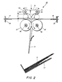
- knife folder 60 includes a blade 70 that is fixidly secured by bolds 64 and 65 to rodes 72 (not shown) and 73. Also mounted on the rods are nip rollers 61, 62, 63 and a fourth nip roller not shown with both the nip rollers and the blade being moveable up and down by conventional means a predetermined distrance D as shown in Figure 2.
- the function of blade 70 is to buckle the sheet, and begin to direct it into the folding nip between cylinders 66 and 67.
- the impro vement of this particular blade control of sheets is that the sheets are positioned over the folding cylinders in the precise time required by the machine feeding the sheets without damage to the sheets.
- the key feature of the present invention is that a buckling blade 70 is used only to facilitate downward collapse of a sheet the predetermined distrance D. The continued movement of the blade downward brings nip rollers 61 and 62 into engagement with folding rollers 66 and 67 without the point of blade 70 coming in contact with either roller 66 or 67 or the nip formed between the two rollers.
- nip rollers 6p1 and 62 and folding rollers 66 and 67 and having a sheet 31 therebetween causes the sheet to continue to gently buckle down into the folding nip between rollers 66 and 67.
- positive acquisition of the sheet in the folding nip is obtained without damage to the sheet by the blade while at the same time reducing the potential of sheet movement over the center of the folding nip.
- the knife folder apparatus 60 is adjusted at 78 for handling a wide variety of sheet sizes. To make an adjustment, all one need do is move adjustable guide 78 toward fixed support 79.
- the sheets are supported on member 77 for transport into the folder and registered against members 76 and after folding has occurred the folded sheets exit folding cylinders 66 and 67 and are guided by appropriate baffles into catch tray 37.
- the folding cylinders 66 and 67 are driven in opposite directions by conventional means on shafts 68 and 69. If one desired, rollers 61 and 62 could be the drive rollers and rollers 66 and 67 idler rollers.
- Registration members 76 are slidable backwards and forwards to adjust for various incoming sheet sizes.
- the improved folder 60 is quite different from a knife folder where the knife driving the sheet into the folding nip creates the fold.
- the knife folder of the present invention employes a blade 70 which bends a sheet 31 to establish a buckle in the sheet and gently but positively directs the sheet into pinch rollers 61 and 63 as shown in Figure 3 for folding.
- the pinch rollers may be stationary until the buckle of the sheet by knife 70 is established, then actuated to crease the sheet in conjunction with rollers 66 and 67. This reduces the potential for disturbance of a copy being centered over pinch rollers 66 and 67 as well as other damage to the copy that could be caused by knife action.
- the knife or buckling blade 70 contacts the copy sheet 31 before nip or pinch rollers 61 and 62 but does not jam the sheet into folding cylinders 66 and 67.
- knife 70 insures downward collapse of the copy sheet into the cylinders 66 and 67.
- the positive drive of the nip rollers will reliably introduce the copy sheet into the folding cylinder nip between rollers 66 and 67.
- the blade will then insure the downward direction of collapse of the copy sheet. By protruding the blade just below the nip rollers, the disturbance of the copy sheet is minimal and there is no likelyhood of damaging the copy sheet by jamming the blade into the folding cylinder nip.
- the folder employs a blade and nip rollers to buckle a sheet into a folding cylinder pair with the folding cylinder pair taking the initially buckled sheet and applying a permanent fold in the sheet and then passing the sheet into an output tray.
- the nip rollers work in conjuction with the folding cylinder paid to gently turn an initial buckle in the sheet into a complete fold.
Abstract
Description
- This invention relates generally to a knife folder particularly, but not exclusively, for use with an electrophotographic printing machine for folding sheets exiting the machine.
- As cut and folded web sections emerge from other press folder operations, they often are given a final fold by means of a blade which descends in a chopping motion when a sheet is in position under it. The blade pushes the sheet down between two nip rollers, creating a fold at that point. A knife folder requires deskewed and centered copy over the folding nip rollers or the sheet may be folded off center or crooked. Also, caution in the blade positioning relative to the nip rollers is essential or the sheet may be damaged or acquired too slowly. Accordingly, it is highly desirable to simplify the folding of sheets without damage while at the same time improving the reliability of the folder.
- US-A-1 124 375 discloses a folding and stapling device in which a folder blade drives and creases collected sheets into a receiving head and clips of an arm member.
- US-A-4 508 527 discloses a method and apparatus for quantitatively dividing zig-zag folded sheets. A sheet of paper having a plurality of linear perforations is continuously transferred vertically through a roller and is folded in zig-zag form by operation of a crank mechanism.
- In accordance with the present invention claimed in claim 1 below, there is provided an improved knife folder in which a blade collapses a sheet into position to be gently buckled by nip rollers into a nip formed by a pair of folding cylinders that apply a final fold to the sheet and thereby insuring positive acquisition of the sheet, elimination of a critical set up and the potential for knife related copy damage while reducing potential for disturbing the centering of the sheet over the folding cylinders.
- While the present invention will hereinafter be described in connection with a preferred embodiment thereof, it will be understood that it is not intended to limit the invention to that embodiment. On the contrary, it is intended to cover all alternatives, modifications, and equivalents that may be included within the scope of the invention as defined by the appended claims.
- For a general understanding of the features of the present invention, reference is made to the drawings. In the drawings, like reference numerals have been used throughout to designate idential elements.
- Figure 1 is a schematic showing an electrophotographic machine feeding sheets to be folded by the improved folder of the present invention. However, it will become apparent from the following discussion that the present folder could be used to fold sheets from any machine, and is not limited to the embodiment shown herein.
- Figure 2 is a fragmentary elevational end view of Figure 3 along line A-A.
- Figure 3 is a partial side view of the apparatus of the present invention.
- Figure 4 is a partial isometric view of the knife folder of the present invention showing the relationship between the knife, nip rollers and folding cylinders.
- Turning now to Figure 1,
printing machine 10 includesconventional controller 58 and a recirculatingdocument handling system 12 for advancing successive original documents onto the platen of theprecessing module 14. Inasmuch as the art of electrophotographic printing is well known, the operation of the various processing stations employed inprocessing module 14 will be described briefly. -
Processing module 14 employs abelt 16 having a photoconductive surface deposed on a conductive substrate. Preferably the photoconductive surface is made from a selenium alloy with the conductive substrate being preferably made from an aluminum alloy which is electrically grounded.Belt 16 advances successive portions of the p hotoconductive surface sequentially through the various processing stations disposed about the path of movement thereof.Belt 16 is entrained aboutstripping roller 18,tensioning roller 20 anddrive roller 22.Drive roller 22 is coupled to a suitable motor so as to rotate andadvance belt 16. - Initially, a portion of
belt 16 passes through charging station A. At charging station A, acorona generating device 24 charges the photoconductive surface ofbelt 16 to a relatively high, substantially uniform potential. - After the photoconductive surface of
belt 16 is charged, the charged portion thereof is advanced through exposure station B. At exposure station B, an original document is advanced by the recirculatingdocument handling system 12 to atransparent platen 26.Lamps 28 flash light rays onto the original document. The light rays reflected from the original document are transmitted throughlens 30 forming a light image thereof.Lens 30 focuses the light image onto the charged portion of the photoconductive surface to selectively dissipate the charge thereon. This records an electrostatic image on the photoconductive surface ofbelt 16 which corresponds to the informational areas contained within the original document. - Thereafter,
belt 16 advances the electrostatic latent image recorded on the photoconductive surface to development station C. At development station C a magnetic brush development system, indicated generally by the reference numeral 32, advances developer material into contact with the latent image. Preferably, magnetic brush development system 32 includes two magneticbrush developer rollers belt 16. - After the electrostatic latent image is developed, belt 16 advances the tone powder image to transfer station D. A sheet of support material is advanced to transfer station D from a copy sheet
stack supporting apparatus corona generating device 42 which sprays ions onto the backside of the copy sheet. This attracts the toner powder image from the photoconductive surface to the copy sheet. After transfer, the copy sheet moves ontoconveyor 44 which advances the sheet to fusing station E. - Fusing station E includes a fuser assembly, indicated generally by the
reference numeral 46, which permanently affixes the transferred powder image to the copy sheet. Preferably,fuser assembly 46 comprises a heatedfuser roller 48 and a back-up roller 50. The copy sheet passes between the fuser roller and back-up roller with the toner powder image contacting the fuser roller. In this manner, the toner powder image is permanently affixed to the copy sheet. After fusing, the copy sheet is either advanced tooutput tray 52, returned toduplex tray 54 for subsequent recycling so as to enable a toner powder image to be transferred to the other side thereof, or if folding is required, directed intofolder 60 that is partially supported by castor mountedsupport 90. The detailed structure ofknife folder 60 will be described hereinafter with reference to Figures 2-4. - Referring now to Figures 2-4, there is shown a fragmentary elevational view illustrating positive
drive knife folder 60 in greater detail. As depicted thereat,knife folder 60 includes ablade 70 that is fixidly secured bybolds 64 and 65 to rodes 72 (not shown) and 73. Also mounted on the rods arenip rollers blade 70 is to buckle the sheet, and begin to direct it into the folding nip betweencylinders buckling blade 70 is used only to facilitate downward collapse of a sheet the predetermined distrance D. The continued movement of the blade downward bringsnip rollers folding rollers blade 70 coming in contact with eitherroller folding rollers rollers - The
knife folder apparatus 60 is adjusted at 78 for handling a wide variety of sheet sizes. To make an adjustment, all one need do is moveadjustable guide 78 towardfixed support 79. The sheets are supported onmember 77 for transport into the folder and registered againstmembers 76 and after folding has occurred the folded sheetsexit folding cylinders catch tray 37. Thefolding cylinders shafts rollers rollers Registration members 76 are slidable backwards and forwards to adjust for various incoming sheet sizes. - In reference to Figures 3 and 4, it can be seen that the improved
folder 60 is quite different from a knife folder where the knife driving the sheet into the folding nip creates the fold. In contrast, the knife folder of the present invention employes ablade 70 which bends a sheet 31 to establish a buckle in the sheet and gently but positively directs the sheet intopinch rollers knife 70 is established, then actuated to crease the sheet in conjunction withrollers pinch rollers blade 70 contacts the copy sheet 31 before nip orpinch rollers folding cylinders controller 58,knife 70 insures downward collapse of the copy sheet into thecylinders rollers - It should now be apparent that an improved knife folder has been disclosed that insured the folding of a sheet along a predictable centerline without risk of damage to the sheet. The folder employs a blade and nip rollers to buckle a sheet into a folding cylinder pair with the folding cylinder pair taking the initially buckled sheet and applying a permanent fold in the sheet and then passing the sheet into an output tray. The nip rollers work in conjuction with the folding cylinder paid to gently turn an initial buckle in the sheet into a complete fold.
Claims (8)
nip means positioned adjacent said folding cylinders and mounted for non-relative movement with respect to said blade; and
support means for supporting said blade and said nip means, said support means being adapted for movement through a predetermined distance such that as said support means is moved said blade contacts the sheet and causes it to collapse toward said folding cylinders and continued movement of said support means brings said nip means into engagement with said folding cylinders and the sheet, whereby the sheet is driven into a nip formed between said folding cylinders, folded and exited therefrom.
Applications Claiming Priority (2)
| Application Number | Priority Date | Filing Date | Title |
|---|---|---|---|
| US759707 | 1985-07-29 | ||
| US06/759,707 US4643705A (en) | 1985-07-29 | 1985-07-29 | Positive drive knife folder |
Publications (3)
| Publication Number | Publication Date |
|---|---|
| EP0211562A2 true EP0211562A2 (en) | 1987-02-25 |
| EP0211562A3 EP0211562A3 (en) | 1988-03-30 |
| EP0211562B1 EP0211562B1 (en) | 1990-03-14 |
Family
ID=25056660
Family Applications (1)
| Application Number | Title | Priority Date | Filing Date |
|---|---|---|---|
| EP86305644A Expired - Lifetime EP0211562B1 (en) | 1985-07-29 | 1986-07-23 | Knife sheet-folder |
Country Status (4)
| Country | Link |
|---|---|
| US (1) | US4643705A (en) |
| EP (1) | EP0211562B1 (en) |
| JP (1) | JP2573578B2 (en) |
| DE (1) | DE3669487D1 (en) |
Cited By (2)
| Publication number | Priority date | Publication date | Assignee | Title |
|---|---|---|---|---|
| GB2211823A (en) * | 1987-10-31 | 1989-07-12 | Donald Alexander | Loading notes into carrier for pneumatic conveyor |
| EP0795507A3 (en) * | 1996-03-12 | 1998-07-08 | Francotyp-Postalia Aktiengesellschaft & Co. | Device for folding sheets |
Families Citing this family (57)
| Publication number | Priority date | Publication date | Assignee | Title |
|---|---|---|---|---|
| JPH02255464A (en) * | 1989-03-27 | 1990-10-16 | Horii Kk | Folding machine |
| JPH0475964A (en) * | 1990-07-13 | 1992-03-10 | Tokyo Kikai Seisakusho Ltd | Chopper folded paper restricting device for rotary press |
| JP2553285B2 (en) * | 1992-06-12 | 1996-11-13 | 天龍工業株式会社 | Directionally variable seat |
| US5364332A (en) * | 1993-07-01 | 1994-11-15 | Xerox Corporation | Soft nip folder |
| US5377965A (en) * | 1993-11-08 | 1995-01-03 | Xerox Corporation | Automatic on-line signature booklets finisher for electronic printers |
| US5547176A (en) * | 1994-12-15 | 1996-08-20 | Xerox Corporation | Apparatus and method for binding pseudo-signatures into a booklet |
| DE19611787C2 (en) * | 1996-03-12 | 1999-11-11 | Francotyp Postalia Gmbh | Arrangement for folding sheets |
| US5788130A (en) * | 1997-01-21 | 1998-08-04 | Todd Motion Controls, Inc. | Sock processing apparatus and method |
| DE19814917C2 (en) * | 1998-04-03 | 2000-09-21 | Texpa Maschinenbau Gmbh & Co K | Plant for folding a textile web section |
| WO2000018583A1 (en) * | 1998-09-29 | 2000-04-06 | Hewlett-Packard Company | Method and apparatus for making booklets |
| US6192655B1 (en) * | 1999-08-31 | 2001-02-27 | Todd Motion Controls, Inc. | Hosiery manipulation device and method |
| US6645134B2 (en) * | 2001-09-12 | 2003-11-11 | Vijuk Equipment, Inc. | Outsert-forming apparatus |
| US6656103B1 (en) * | 2000-11-28 | 2003-12-02 | Vijuk Equipment, Inc. | Informational item forming machine and method |
| GB0107883D0 (en) * | 2001-03-29 | 2001-05-23 | Morgana Systems Ltd | Folding machine |
| JP3778030B2 (en) * | 2001-08-23 | 2006-05-24 | コニカミノルタホールディングス株式会社 | Sheet folding method, sheet folding apparatus, sheet post-processing apparatus, and image forming apparatus |
| US6878104B2 (en) | 2001-10-05 | 2005-04-12 | Hewlett-Packard Development Company, L.P. | Variable media thickness folding method |
| US6855101B2 (en) * | 2001-10-05 | 2005-02-15 | Hewlett-Packard Development Company, L.P. | Sheet folding apparatus |
| US6808479B2 (en) | 2001-10-05 | 2004-10-26 | Hewlett-Packard Development Company, L.P. | Thick media folding method |
| US6673002B2 (en) | 2001-10-05 | 2004-01-06 | Hewlett-Packard Development Company, L.P. | Sheet folding apparatus with pivot arm fold rollers |
| US6939284B2 (en) * | 2001-10-05 | 2005-09-06 | Hewlett-Packard Development Company, L.P. | Sheet folding apparatus with rounded fold blade |
| US6623415B2 (en) * | 2001-12-21 | 2003-09-23 | First Data Corporation | Sheet folding systems and methods |
| DE20204721U1 (en) * | 2002-03-25 | 2002-06-13 | Oppenweiler Binder Gmbh Maschb | Folding machine with a cross break module |
| EP1348664B1 (en) * | 2002-03-25 | 2006-08-02 | MASCHINENBAU OPPENWEILER BINDER GmbH & Co. KG | Folding machine with a side-lay device |
| JP4021705B2 (en) * | 2002-05-23 | 2007-12-12 | キヤノンファインテック株式会社 | Sheet post-processing apparatus and image forming apparatus provided with the apparatus |
| US6592506B1 (en) * | 2002-06-25 | 2003-07-15 | Pitney Bowes Inc. | Folder apparatus |
| US6773388B2 (en) | 2002-06-28 | 2004-08-10 | Pitney Bowes Inc. | Folder apparatus with transverse loading |
| US6837841B2 (en) | 2002-09-30 | 2005-01-04 | Hewlett-Packard Development Company, L.P. | Method and apparatus for sheet folding |
| US7216012B2 (en) * | 2003-04-14 | 2007-05-08 | First Data Corporation | Auction systems and methods for selecting inserts for direct mailings |
| US6895302B2 (en) * | 2003-04-14 | 2005-05-17 | First Data Corporation | Systems and methods for allocating excess space associated with mailings |
| US6829519B2 (en) * | 2003-04-14 | 2004-12-07 | First Data Corporation | Systems for assembling mailings and methods for external control thereof |
| JP2005035682A (en) * | 2003-07-15 | 2005-02-10 | Komori Corp | Chopper table |
| US6997450B2 (en) * | 2003-10-09 | 2006-02-14 | Hewlett-Packard Development Company, L.P. | Sheet folding and accumulation system for a booklet maker |
| US7962355B2 (en) * | 2004-06-30 | 2011-06-14 | First Data Corporation | Presentation instrument production equipment and methods |
| US7470227B2 (en) * | 2004-08-24 | 2008-12-30 | Ricoh Company, Ltd. | Paper folding apparatus and image forming apparatus using the same |
| JP2006069763A (en) * | 2004-09-03 | 2006-03-16 | Fuji Xerox Co Ltd | Sheet folding device |
| NL1027125C2 (en) * | 2004-09-28 | 2006-03-29 | Infostop B V | Dispensing device, collection mechanism therefor and method for dispensing sheets. |
| US7175586B2 (en) * | 2005-03-21 | 2007-02-13 | Vijuk Equipment, Inc. | Methods of forming outserts |
| US20070015649A1 (en) * | 2005-07-14 | 2007-01-18 | First Data Corporation | Flow folder apparatus and methods |
| US7516949B2 (en) * | 2005-08-10 | 2009-04-14 | First Data Corporation | Sideways sheet feeder and methods |
| US20070207910A1 (en) * | 2006-03-03 | 2007-09-06 | Vijuk Equipment, Inc. | Outsert-forming machine and method |
| JP4872455B2 (en) * | 2006-05-24 | 2012-02-08 | コニカミノルタビジネステクノロジーズ株式会社 | Paper folding device and paper post-processing device |
| FR2907654B1 (en) * | 2006-10-31 | 2010-01-29 | Georgia Pacific France | PROCESS, MANUFACTURING DEVICE AND ASSOCIATED ROLLS FORMED OF CUTTING SHEETS AND ALTERNATE PREDECOUPLES |
| US11297984B2 (en) * | 2006-10-31 | 2022-04-12 | Gpcp Ip Holdings Llc | Automatic napkin dispenser |
| US8606670B2 (en) * | 2007-01-02 | 2013-12-10 | First Data Corporation | Integrated communication solution |
| JP2009029523A (en) * | 2007-07-24 | 2009-02-12 | Toshiba Corp | Folding device and device having the same, and folding method |
| DE102008039049A1 (en) | 2007-10-12 | 2009-04-16 | Bdt Ag | Folding unit for use in folding device for folding i.e. sheet of paper, has folding rollers driven in rotating manner such that pre-folded substrate is driven-out from rollers by rotating motion of rollers in folding position |
| US7537556B2 (en) * | 2007-10-25 | 2009-05-26 | Xerox Corporation | High capacity knife folding system |
| EP2100841A1 (en) | 2008-03-10 | 2009-09-16 | Neopost Technologies | Folder for folding paper sheets |
| JP5002529B2 (en) * | 2008-05-22 | 2012-08-15 | デュプロ精工株式会社 | Paper folding mechanism and paper folding device |
| JP5186406B2 (en) * | 2009-02-06 | 2013-04-17 | デュプロ精工株式会社 | Paper folding mechanism and paper folding device |
| JP5625722B2 (en) * | 2010-02-04 | 2014-11-19 | 株式会社リコー | Sheet folding apparatus and image forming apparatus |
| JP5555096B2 (en) * | 2010-08-19 | 2014-07-23 | キヤノン株式会社 | Sheet processing apparatus and image forming apparatus |
| US10383489B2 (en) | 2012-02-10 | 2019-08-20 | Gpcp Ip Holdings Llc | Automatic napkin dispenser |
| US10363766B2 (en) | 2013-03-15 | 2019-07-30 | G&K-Vijuk Intern. Corp. | Information item forming machine with visual inspection unit and method for forming and sorting informational items |
| US9604811B2 (en) | 2013-10-01 | 2017-03-28 | Georgia-Pacific Consumer Products Lp | Automatic paper product dispenser with data collection and method |
| CN110494070A (en) | 2017-05-10 | 2019-11-22 | Gpcp知识产权控股有限责任公司 | Automatic paper product distributor and associated method |
| US20210387794A1 (en) * | 2020-06-12 | 2021-12-16 | Wisconsin Alumni Research Foundation | Medical Facemask Dispenser |
Citations (5)
| Publication number | Priority date | Publication date | Assignee | Title |
|---|---|---|---|---|
| GB774410A (en) * | 1954-07-12 | 1957-05-08 | Camco Machinery Ltd | Improvements in sheet conveying devices for paper sheet handling machinery |
| DD99345A1 (en) * | 1972-01-12 | 1973-08-13 | ||
| US3901501A (en) * | 1969-11-22 | 1975-08-26 | Oppenweiler Binder & Co Maschb | Device for making a thrice parallel folded sheet in which the open bent covers are directed towards the middle |
| US4419088A (en) * | 1981-06-19 | 1983-12-06 | Nemec David G | Gate folding apparatus |
| US4508527A (en) * | 1982-09-20 | 1985-04-02 | Tadao Uno | Method and apparatus for quantitatively dividing zigzag folded sheet of paper |
Family Cites Families (2)
| Publication number | Priority date | Publication date | Assignee | Title |
|---|---|---|---|---|
| US538609A (en) * | 1895-04-30 | dextee | ||
| US1124375A (en) * | 1910-02-11 | 1915-01-12 | Wood Newspaper Mach Corp | Folding and stapling device. |
-
1985
- 1985-07-29 US US06/759,707 patent/US4643705A/en not_active Expired - Lifetime
-
1986
- 1986-07-14 JP JP61165448A patent/JP2573578B2/en not_active Expired - Lifetime
- 1986-07-23 DE DE8686305644T patent/DE3669487D1/en not_active Expired - Fee Related
- 1986-07-23 EP EP86305644A patent/EP0211562B1/en not_active Expired - Lifetime
Patent Citations (5)
| Publication number | Priority date | Publication date | Assignee | Title |
|---|---|---|---|---|
| GB774410A (en) * | 1954-07-12 | 1957-05-08 | Camco Machinery Ltd | Improvements in sheet conveying devices for paper sheet handling machinery |
| US3901501A (en) * | 1969-11-22 | 1975-08-26 | Oppenweiler Binder & Co Maschb | Device for making a thrice parallel folded sheet in which the open bent covers are directed towards the middle |
| DD99345A1 (en) * | 1972-01-12 | 1973-08-13 | ||
| US4419088A (en) * | 1981-06-19 | 1983-12-06 | Nemec David G | Gate folding apparatus |
| US4508527A (en) * | 1982-09-20 | 1985-04-02 | Tadao Uno | Method and apparatus for quantitatively dividing zigzag folded sheet of paper |
Cited By (4)
| Publication number | Priority date | Publication date | Assignee | Title |
|---|---|---|---|---|
| GB2211823A (en) * | 1987-10-31 | 1989-07-12 | Donald Alexander | Loading notes into carrier for pneumatic conveyor |
| GB2211823B (en) * | 1987-10-31 | 1992-01-08 | Donald Alexander | Loading apparatus |
| EP0795507A3 (en) * | 1996-03-12 | 1998-07-08 | Francotyp-Postalia Aktiengesellschaft & Co. | Device for folding sheets |
| US6042529A (en) * | 1996-03-12 | 2000-03-28 | Francotyp-Postalia Ag & Co. | Configuration for folding sheets |
Also Published As
| Publication number | Publication date |
|---|---|
| JPS6227276A (en) | 1987-02-05 |
| EP0211562B1 (en) | 1990-03-14 |
| JP2573578B2 (en) | 1997-01-22 |
| DE3669487D1 (en) | 1990-04-19 |
| EP0211562A3 (en) | 1988-03-30 |
| US4643705A (en) | 1987-02-17 |
Similar Documents
| Publication | Publication Date | Title |
|---|---|---|
| EP0211562B1 (en) | Knife sheet-folder | |
| EP0632340B1 (en) | Soft nip sheet folding apparatus | |
| US5285249A (en) | Finishing apparatus for stapling sheets stacked first-to-last or last-to-first | |
| EP0541260B1 (en) | Apparatus for deskewing and side registering a sheet | |
| US5288062A (en) | High capacity compiler with vertically adjustable sheet discharge and acquire means | |
| US3942785A (en) | Self-actuating sheet inverter reverser | |
| US4595187A (en) | Saddle stapler accessory | |
| US5202737A (en) | Method and apparatus for decurling sheets in a copying device | |
| US4669719A (en) | Sheet rotation and registration vertical transport | |
| CA1038322A (en) | Sheet reversing mechanism | |
| GB2082551A (en) | Laterally offsetting and stacking sheets | |
| GB1595609A (en) | Sheet handling | |
| US4632533A (en) | Off-set nip roll decurler | |
| JPH07102906B2 (en) | Sheet material stack holding tray | |
| US5539508A (en) | Variable length transfer assist apparatus | |
| US5013026A (en) | Sheet stacking and inverting apparatus | |
| US4364550A (en) | Corrugation venturi paper feeder | |
| US3936044A (en) | Adjustable sheet guide | |
| US4994864A (en) | Copy sheet skew adjustment device | |
| JPH0672641A (en) | Sheet collecting and feeding-out device | |
| US5159391A (en) | Electrophotographic image recording apparatus with feed rollers for orientating a sheet upwardly at a transfer station | |
| JPH03138255A (en) | Dynamic end guide for side matching system | |
| EP0031668B1 (en) | Sheet feeding and registering apparatus and document copying machine incorporating same | |
| US4664509A (en) | Dual mode document handling apparatus | |
| US4079876A (en) | Computer forms feeder |
Legal Events
| Date | Code | Title | Description |
|---|---|---|---|
| PUAI | Public reference made under article 153(3) epc to a published international application that has entered the european phase |
Free format text: ORIGINAL CODE: 0009012 |
|
| AK | Designated contracting states |
Kind code of ref document: A2 Designated state(s): DE FR GB |
|
| PUAL | Search report despatched |
Free format text: ORIGINAL CODE: 0009013 |
|
| AK | Designated contracting states |
Kind code of ref document: A3 Designated state(s): DE FR GB |
|
| 17P | Request for examination filed |
Effective date: 19880914 |
|
| 17Q | First examination report despatched |
Effective date: 19881109 |
|
| GRAA | (expected) grant |
Free format text: ORIGINAL CODE: 0009210 |
|
| AK | Designated contracting states |
Kind code of ref document: B1 Designated state(s): DE FR GB |
|
| REF | Corresponds to: |
Ref document number: 3669487 Country of ref document: DE Date of ref document: 19900419 |
|
| ET | Fr: translation filed | ||
| PLBE | No opposition filed within time limit |
Free format text: ORIGINAL CODE: 0009261 |
|
| STAA | Information on the status of an ep patent application or granted ep patent |
Free format text: STATUS: NO OPPOSITION FILED WITHIN TIME LIMIT |
|
| 26N | No opposition filed | ||
| PGFP | Annual fee paid to national office [announced via postgrant information from national office to epo] |
Ref country code: FR Payment date: 20010712 Year of fee payment: 16 |
|
| PGFP | Annual fee paid to national office [announced via postgrant information from national office to epo] |
Ref country code: DE Payment date: 20010716 Year of fee payment: 16 |
|
| PGFP | Annual fee paid to national office [announced via postgrant information from national office to epo] |
Ref country code: GB Payment date: 20010718 Year of fee payment: 16 |
|
| REG | Reference to a national code |
Ref country code: GB Ref legal event code: IF02 |
|
| PG25 | Lapsed in a contracting state [announced via postgrant information from national office to epo] |
Ref country code: GB Free format text: LAPSE BECAUSE OF NON-PAYMENT OF DUE FEES Effective date: 20020723 |
|
| PG25 | Lapsed in a contracting state [announced via postgrant information from national office to epo] |
Ref country code: DE Free format text: LAPSE BECAUSE OF NON-PAYMENT OF DUE FEES Effective date: 20030201 |
|
| GBPC | Gb: european patent ceased through non-payment of renewal fee |
Effective date: 20020723 |
|
| PG25 | Lapsed in a contracting state [announced via postgrant information from national office to epo] |
Ref country code: FR Free format text: LAPSE BECAUSE OF NON-PAYMENT OF DUE FEES Effective date: 20030331 |
|
| REG | Reference to a national code |
Ref country code: FR Ref legal event code: ST |